1
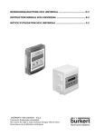
BEDIENUNGSANLEITUNG DURCHFLUSS-TRANSMITTER 8035
D-1
INSTRUCTION MANUAL FLOW TRANSMITTER 8035
E-1
NOTICE D'UTILISATION TRANSMETTEUR DE DEBIT 8035
F-1
*****
©BÜRKERT 1998 00555881-Sep05 - Ind_D
Technische Änderungen vorbehalten
We reserve the right to make technical changes without notice
Sous réserve de modifications techniques
INHALT
DURCHFLUSS-TRANSMITTER 8035
1
EINFÜHRUNG ..................................................................................................................................D-3
1.1
1.2
1.3
1.4
Auspacken und Kontrolle .......................................................................................................................................................D-3
Allgemeine Hinweise ...............................................................................................................................................................D-3
Sicherheitshinweise ................................................................................................................................................................D-3
Elektromagnetische Verträglichkeit......................................................................................................................................D-3
2
BESCHREIBUNG .............................................................................................................................D-4
2.1
2.2
2.3
2.4
2.5
Bestell-Nummern Elektronikmodul SE35...........................................................................................................................D-4
Beschreibung des Typenschilds .........................................................................................................................................D-4
Aufbau und Messprinzip .........................................................................................................................................................D-5
Abmessungen ...........................................................................................................................................................................D-6
Technischen Daten ..................................................................................................................................................................D-7
3
INSTALLATION .................................................................................................................................D-9
3.1
3.2
3.3
Allgemeine Hinweise zum Einbau ........................................................................................................................................D-9
Einbau ..................................................................................................................................................................................... D-10
Elektrischer Anschluss ....................................................................................................................................................... D-11
3.3.1 Allgemeine Hinweise zum elektrischen Anschluss ........................................................................................ D-11
3.3.2 Elektrischer Anschluss, Transmitter ohne Relais, mit EN 175301-803 Stecker ..................................... D-13
3.3.3 Einsatz der Kabelschellen ..................................................................................................................................... D-14
3.3.4 Einstellung des Schalters FLOW SENSOR ..................................................................................................... D-15
3.3.5 Elektrischer Anschluss, Transmitter 12-30 VDC, ohne Relais, mit Kabelverschraubungen ................ D-15
3.3.6 Elektrischer Anschluss, Transmitter 12-30 VDC, mit Relais und Kabelverschraubungen ..................... D-17
3.3.7 Elektrischer Anschluss, Transmitter 115/230 VAC, ohne Relais, mit Kabelverschraubungen ............. D-19
3.3.8 Elektrischer Anschluss, Transmitter 115/230 VAC, mit Relais und Kabelverschraubungen ................ D-21
4
KONFIGURIERUNG ......................................................................................................................D-23
4.1
4.2
4.3
Beschreibung des Transmitters Programmiertasten .................................................................................................... D-24
Hauptmenü ............................................................................................................................................................................. D-24
Kalibriermenü ......................................................................................................................................................................... D-25
4.3.1 Sprache ..................................................................................................................................................................... D-26
4.3.2 Maßeinheiten ............................................................................................................................................................ D-26
4.3.3 K-Faktor ..................................................................................................................................................................... D-27
4.3.4 Stromausgang.......................................................................................................................................................... D-27
4.3.5 Pulsausgang ............................................................................................................................................................. D-28
4.3.6 Relais ......................................................................................................................................................................... D-28
4.3.7 Filterfunktion ............................................................................................................................................................. D-29
4.3.8 Totalisator .................................................................................................................................................................. D-30
Test Menü ............................................................................................................................................................................... D-30
4.4.1 Offset-Abgleich ....................................................................................................................................................... D-30
4.4.2 Span-Abgleich ......................................................................................................................................................... D-31
4.4.3 Frequenzanzeige ..................................................................................................................................................... D-31
4.4.4 Durchfluss-Simulation ............................................................................................................................................ D-31
4.4
5
WARTUNG ......................................................................................................................................D-32
5.1
5.2
5.3
Hinweis Störung.................................................................................................................................................................... D-32
Basis Einstellung des 8035 bei Auslieferung ................................................................................................................ D-32
Ersatzteil-Stückliste .............................................................................................................................................................. D-33
ANHANG...........................................................................................................................................D-34
Durchfluss-Diagramm (l/min, DN in mm und m/s) ........................................................................................................ D-34
Durchfluss-Diagramm (US-gallon/min, DN in inch und ft/s) ...................................................................................... D-35
EG-Konformitäts-Erklärung .................................................................................................................................................F-35
D-2-
1 EINFÜHRUNG
DURCHFLUSS-TRANSMITTER 8035
Sehr geehrter Kunde,
1.3 Sicherheitshinweise
LESEN SIE DIESE BEDIENUNGSANLEITUNG GRÜNDLICH, BEVOR
SIE DAS GERÄT MONTIEREN UND IN
BETRIEB NEHMEN.
Bürkert stellt verschiedene Transmitter her.
Jedes kann in einer Vielzahl von Applikationen eingesetzt werden. Gerne beraten wir
hierzu intensiv.
Es liegt jedoch in der Verantwortung des
Kunden, das zu seiner Applikation optimal
passende Gerät zu wählen, es korrekt zu
installieren und instandzuhalten. Besonders
ist hierbei die chemische Beständigkeit des
Bürkert- Produktes gegenüber den Medien
sicherzustellen, die in direkten Kontakt mit
dem Produkt kommen.
1.1 Auspacken und Kontrolle
Bitte überprüfen Sie die Lieferung auf Vollständigkeit und Transportschäden.
Um sicherzustellen, dass Sie das richtige
Gerät erhalten haben, vergleichen Sie die
Typenbezeichnung auf dem Typenschild mit
der nebenstehenden Liste. Bei Verlust oder
Schäden wenden Sie sich an Ihre BürkertNiederlassung.
Dieses Symbol erscheint in der
Bedienungsanleitung jedesmal
wenn besondere Vorsicht
geboten ist, um eine einwandfreie Installation, Funktion und
Betriebssicherheit des Gerätes
zu gewährleisten.
1.2 Allgemeine Hinweise
Diese Bedienungsanleitung enthält keine
Garantiezusagen. Wir verweisen hierzu auf
unsere allgemeinen Verkaufs- und Lieferbedingungen.
Einbau und/oder Reparatur dürfen nur durch
eingewiesenes Personal erfolgen. Sollten
bei der Installation oder der Inbetriebnahme
Schwierigkeiten auftreten, setzen Sie sich
bitte sofort mit unserer nächsten Niederlassung in Verbindung.
1.4 Elektromagnetische Verträglichkeit
Dieses Produkt erfüllt die grundlegenden
Anforderungen der Richtlinien
2004/108/EG (EMV) und 73/23/EG (DBT).
Dazu müssen die elektrischen Anschlussvorschriften befolgt werden.
Die Prüfung der Geräte wurde entsprechend den folgenden EMV-Normen
durchgeführt:
- EN 61000-6-3
- EN 61000-6-2
- EN 61010-1
D-3-
DURCHFLUSS-TRANSMITTER 8035
2 BESCHREIBUNG
2.1 Bestell-Nummern Elektronikmodul SE35
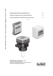
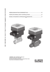
Der Durchfluss-Transmitter 8035 besteht aus einem Elektronikmodul SE35, der auf einem
Fitting S030 mit PVDF-Schaufelrad aufgebaut ist.
Das Fitting S030 und das Elektronikmodul SE35 werden separat bestellt.
Alle Informationen betreffend Fittings S030 befinden sich in der entsprechenden Bedienungsanleitung.
Ausgänge
1)
Totalisator
Relais
Versorg.
Spannung
Sensor
4...20 mA + Puls
2
-
12-30 VDC
Spule
EN 175301-803
423915
4...20 mA + Puls
2
-
12-30 VDC
Hall
EN 175301-803
444005
4...20 mA + Puls
2
-
12-30 VDC
Spule
2xKabelverschraubungen
423916
4...20 mA + Puls
2
-
12-30 VDC
Hall
2xKabelverschraubungen
444006
4...20 mA +
Puls1)
2
-
12-30 VDC
Hall
2xKabelverschraubungen
553432
4...20 mA + Puls
2
-
115/230
VAC
Hall
2xKabelverschraubungen
423922
4...20 mA + Puls
2
2
12-30 VDC
Spule
2xKabelverschraubungen
423918
4...20 mA + Puls
2
2
12-30 VDC
Hall
2xKabelverschraubungen
444007
4...20 mA +
Puls1)
2
2
12-30 VDC
Hall
2xKabelverschraubungen
553433
4...20 mA + Puls
2
2
115/230 VAC
Hall
2xKabelverschraubungen
423924
UR und CSA Zulassungen, werden deshalb mit Logo
Elektrischer Anschluss
BestellNr
gekennzeichnet.
2.1 Beschreibung des Typenschilds
Made in France
1
2
FLOW:SE35/8035 HALL SENSOR N=10000
12-30VDC 4-20mA REL:220VAC/3A
00444007
W45LG
9
8 7
1.
3
4
5
6
D-4-
2.
3.
4.
5.
6.
7.
8.
9.
Gemessene Größe und Typ des
Transmitters
Typ des Messelements
Serien-Nr
Relais-Angaben
Hersteller-Nr
CE-Logo
Stromausgang
Versorgungsspannung
Bestell-Nr
2 BESCHREIBUNG
DURCHFLUSS-TRANSMITTER 8035
2.3 Aufbau und Messprinzip
Aufbau
Messprinzip
Der Durchfluss-Transmitter 8035 besteht
aus einem Kunststoffgehäuse (PC) IP65
direkt auf das Fitting S030, durch Schnellverschluss, montiert. Das Gehäuse enthält
die Elektronik Platine mit Anzeige und
Programmiertasten sowohl wie den Messwertaufnehmer. Das Flügelrad ist in dem
Fitting eingebaut
Der Messumformer-Teil dient zur Messwertaufbereitung und Anzeige des Momentanwertes.
Der elektrische Anschluss erfolgt über
einen 4-poligen Stecker (EN175301-803)
oder über Klemmen durch zwei Kabelverschraubungen.
4 Magnete sind in dem Schaufelrad eingesetzt. In Bewegung gesetzt durch die
strömende Flüssigkeit, erzeugen sie im
Messwertaufnehmer (Sinusausgang oder
Pulsausgang) eine Mess-Frequenz, die der
Durchflussgeschwindigkeit der Flüssigkeit
proportional ist. Ein Umrechnungs-Faktor,
(K-Faktor) spezifisch zu jeder Nennweite
und jedem Werkstoff, ist nötig, um die Durchflussmenge zu erstellen. Dieser Koeffizient
(in Impulse/l) ist in der Bedienungsanleitung
des Inline Fittings (S020) zu entnehmen.
Der Messumformer ohne Relais arbeitet
in 2-Leiter-Technik. Als Ausgangssignal,
proportional zur Durchflussmenge, steht
ein eingeprägtes Normsignal 4...20 mA zur
Verfügung. Ein polarisierter potentialfreien
Pulsausgang ist verfügbar.
Der Messumformer mit 2 zusätzlichen Relais
arbeitet in 3-Leiter-Technik. Die Grenzwerte
sind frei einstellbar.
Der Durchfluss-Transmitter 8035 mit
Pulsausgang-Sensor kann eine Durchflussmenge ab 0,3 m/s Durchflussgeschwindigkeit erfassen.
Der Durchfluss-Transmitter 8035 mit Sinusausgang-Sensor kann eine Durchflussmenge ab 0,5 m/s
Durchflussgeschwindigkeit erfassen.
D-5-
2 BESCHREIBUNG
DURCHFLUSS-TRANSMITTER 8035
2.4 Abmessungen
88
21
91
180
88
Die Größe H ist von dem
Anschluss-Typ und Werkstoff
des Fittings unhabhängig.
Fig. 2.1 Durchfluss-Transmitter Abmessungen
D-6-
DN
(mm)
H
(mm)
06
134
08
134
15
139
20
137
25
137
32
140
40
144
50
151
65
151
H
114
75
104
105
116
103
2 BESCHREIBUNG
DURCHFLUSS-TRANSMITTER 8035
2.5 Technische Daten
Rohrdurchmesser
Umgebungs
Umgebungstemperatur
Relative Feuchtigkeit
Schutzart
Durchflussmessung
Messbereich
Messgenauigkeit
DN6 bis DN65
0 bis 60 °C (Betriebs- und Lager)
max 80 %, nicht kondensierend
IP 65
Sensor mit Pulsausgang: 0.3 bis 10 m/s
Sensor mit Sinusaugang: 0.5 bis 10 m/s
1. Mit anlagespezifischer Kalibrierung oder "Teach-In":
≤ ± 0.5% v.E. (bei 10 m/s) *
2. Mit standard K-Faktor:
≤ ± (0.5% v.E. + 2.5% v.M.) *
Fehler max. [%]
10
v.E. = vom Endwert
v.M. = vom Messwert
8
6
0.5%
v .E. + 2 5. %
v . M.
0.5%
v. E .
4
2
-2
1
2
-4
-8
Max. Viskosität
Max. Feststoffanteil
5
6
7
8
9
10
Kalibrierung mit Teach-In
-10
Max. Mediumstemperatur
4
Typische Bürkert Kurve
Standard Kalibrierung
-6
Linearität
Wiederholbarkeit
Medium
Druckklasse
3
Flüssigkeitsgeschwindigkeit [m/s]
≤ ± 0.5% v.E. (bei 10 m/s) *
0.4% v.M. *
PN 10 (mit Kunststoff Fitting),
PN 16 (mit Metall Fitting), PN 40 auf Anfrage; siehe
Druck-Temperatur-Diagramm, § 3.1
mit Fitting
PVC: 50°C, PP: 80°C
PVDF, Edelstahl, Messing: 100°C
300 cSt.
1%
(*) Unter Referenzbedingungen d.h. Messmedium Wasser, Umgebungs- und Wassertemperatur
20 ° C, Berücksichtigung der Mindestein- und Auslaufstrecken, angepasste Rohrleitungabmessungen.
v.E = vom Endwert (10 m/s); v.M = vom Messwert
D-7-
2 BESCHREIBUNG
DURCHFLUSS-TRANSMITTER 8035
Elektrische Daten
Versorgungsspannung
Umpolung
Stromaufnahme
Stromausgang
Pulsausgang
Relais-Ausgänge
Elektrische Verkabelung
Technische Angaben 115/230 VAC
Versorgende Spannung
12-30 VDC (V+) ± 10%, gefiltert u. geregelt, oder
115/230 VAC - 50/60 Hz (siehe technische
Angaben 115/230 VAC unten)
geschützt
Ohne Pulsausgangstromaufnahme:
≤ 70 mA Ausführung mit Relais
≤ 20 Ausführung ohne Relais
4...20 mA (3-Leitersystem Ausführung mit Relais;
2-Leitersystem Ausführung ohne Relais)
Max. Schleifenwiderstand: 900 Ω bei 30 VDC;
600 Ω bei 24 VDC; 50 Ω bei 12 VDC;
800 Ω bei 230 VAC
polarisiert, potentialfrei, 5 - 30 VDC, 100 mA,
geschützt, Spannungsabfall bei 100 mA: 1,5 VDC
2 Relais, 3 A, 230 VAC, frei einstellbar
Durch abgeschirmtes Kabel, 1,5 mm2 max. Quers
chnitt, 50 m max. Länge (Spannung, Puls- u.
Strom-Ausgang)1,5 mm2 max. Querschnitt (Relais)
27 VDC geregelt
Max. Strom 125 mA
integrierter Schutz: Zeitsicherung 125 mA
Werkstoffe
Fitting und Armatur
Messing, Edelstahl, PVC, PP, PVDF (siehe S030
Bedienungsanleitung)
Flügelrad
PVDF
Flügelrad-Axe und Lager
Keramik
O-Ringe
FPM
Gehäuse
PC
Deckel mit Klappe
PC
Frontanzeige
Polyester
Schrauben
Edelstahl
Stecker, Kabelverschraubungen
PA
Spezifische technische Daten für Produkte mit UR und CSA Zulassungen
Relais-Ausgang
30 VAC und Spitzenwert 42 V max. oder
60 VDC max.
Umgebungstemperatur
40 °C max.
Relative Feuchte
80% max.
Betriebsumgebung
verschmutzungsgrad 2
Anlageklasse
I
Absolute Höhe
2000 m max.
D-8-
3 INSTALLATION
DURCHFLUSS-TRANSMITTER 8035
3.1 Allgemeine Hinweise zum Einbau
Der Transmitter 8035 Kompakt kann nur für Messungen von reinen,
flüssigen, wasserähnlichen Medien verwendet werden
(Feststoffanteil ≤ 1%, Viskosität max. 300 cSt mit On-Site- Kalibration).
Das Gerät ist nicht für die Durchflussmessung von Gasen geeignet.
Druck-Temperatur-Diagramm
Entsprechend den verwendeten Fittingwerkstoffen muss deren Druck-Temperatur-Abhängigkeit berücksichtigt werden.
P (bar)
16
15
14
13
12
PVC + PP
11
10
9
PVDF
8
7
6
5
4
3
2
1
0
-30
-50
-10
Anwendungsbereich
Metall / Metal / Métal
PVDF (PN 10)
PVC (PN 10)
PP (PN 10)
+10
+30
+50
+70
+90
T (°C)
Fig. 3.1 Druck-Temperatur-diagramm
Einbauvorschriften
Das Gerät muss vor dem Regen, vor Ultraviolettbestrahlung und elektromagnetischen Störungen geschützt werden.
Um das Fitting auf die Rohrleitung einzubauen, spezifische Einbau-vorschriften des Fittings
beachten.
D-9-
3 INSTALLATION
DURCHFLUSS-TRANSMITTER 8035
3.2 Einbau
Das Durchfluss-Transmitter-Elektronikmodul
SE35 wird einfach mit spezifischen Fittings
S030 in die Rohrleitung eingebaut.
1. Beim Einbau des Fittings 1 in die Rohrleitung, müssen die Einbauvorschriften
beachtet werden (siehe § 3.1 und in der
Bedienungsanleitung des Fittings enthaltene Einbauvorschriften).
2
2. Das Elektronikmodul SE35 2 mit dem
Bajonett in das Fitting S030 einschieben
und um 90 ° verdrehen.
3
3. Mit der seitlichen Schraube 3 die Einheit
sichern.
1
4. Gemäß § 3.3 verkabeln.
Fig. 3.2 Einbau 8035
D-10-
3 INSTALLATION
DURCHFLUSS-TRANSMITTER 8035
3.3 Elektrischer Anschluss
3.3.1 Allgemeine Hinweise zum elektrischen Anschluss
Das Gerät darf nicht bei angeschlossenem Netzkabel geöffnet werden.
Die Anlage des Gebäudes, in dem der Transmitter installiert ist, muss
mit einem Schalter oder Überlastschalter gesichert sein. Dieser muss
ganz nah an dem Transmitter, zugänglich und als Schaltvorrichtung
für den Transmitter klar ausgezeichnet sein.
Es ist ratsam, Sicherheitsvorrichtungen zu installieren:
Stromversorgung: Sicherung (300 mA- verzögert) und ein Schalter.
Relais: Höchstens 3 A-Sicherung und Überlastschalter (je nach
Anwendung).
Setzen Sie nicht gleichzeitig im Selben Kabel eine gefährliche
Spannung und eine Sicherheits-Kleinspannung an die Relais an.
Nur abgeschirmte Kabel mit einer Temperaturbeständigkeit bis mindestens 80°C
verwenden.
Bei normalen Betriebsbedingungen kann das Messsignal über ein abgeschirmtes
Kabel mit einem Querschnitt von 0,75 mm2 übertragen werden.
Die Signal-Leitung darf nicht in Kontakt mit stromführenden Leitungen mit höherer
Spannung oder Frequenz installiert werden.
Wenn eine kombinierte Installation unumgänglich ist, sollten ein Mindestabstand
von 30 cm eingehalten werden.
Bei Verwendung eines einzigen Kabels muss der Kabeldurchmesser zwischen 6 und
12 mm liegen; Wenn zwei Kabel gebraucht werden, setzen Sie die Mehrwegdichtung
ein und verwenden Sie Kabel mit einem 4-mm-Durchmesser.
Es ist eine gefilterte und geregelte 12-30 VDC Stromversorgung zu verwenden.
Vergewissern Sie die Äquipotentialität der Installation (Stromversorgung - Transmitter
- Flüssigkeit):
- Die verschiedene Erdungspunkte der Installation müssen aneinander angeschlossen
sein, damit die zwischen zwei Erdungspunkten möglicherweise erzeugten Potential
differenzen beseitigt werden.
- Es muss auf vorschriftsmäßige Erdung der Abschirmung geachtet werden.
- Erden Sie den negativen Anschluss der Versorgungsquelle, um Gleichtaktströme zu
unterdrücken. Ist eine direkte Erdung unmöglich,
schließen Sie ein 100 nF/50 V-Kondensator zwischen dem negativen Anschluss
der Versorgungsquelle und der Erde.
Geben Sie darauf besonders acht, wenn das Gerät auf Kunststoffrohren installiert
wird, weil keine direkte Erdung möglich ist.
Zur Ordnungsgemäßen Erdung müssen alle die sich in der Nähe des Geräts
befindenden metallischen Apparate, wie Ventile oder Pumpen, an den selben
Erdungspunkt angeschlossen werden.
D-11-
3 INSTALLATION
DURCHFLUSS-TRANSMITTER 8035
Kompakt-Ausführungen, Prinzipschaltbild einer Äquipotentialität:
Versorgung
12-30VDC
+
(*)
Metallische Rohre
Versorgung
12-30VDC
+
-
Geräte wie Ventil,
Pumpe, usw...
(*)
Kunststoffrohre
(*) ist keine direkte Erdung möglich, schließen Sie einen
100 nF/50V-Kondensator zwischen dem negativen
Anschluss der Versorgungsquelle und der Erde an.
D-12-
DURCHFLUSS-TRANSMITTER 8035
3 INSTALLATION
3.3.2 Elektrischer Anschluss Transmitter ohne Relais, mit EN 175301-803Stecker
Bevor Sie das Gerät verkabeln, lesen Sie bitte § 3.3.1
Aufbau des EN 175301-803-Steckers
[2]
[3]
[4]
[1]
[5]
- Das Innenteil [3] aus dem Außenteil [2] herausnehmen.
- Kabelverschraubung [5] aufschrauben.
- Kabel durch Kabelverschraubung [5] dann durch Teile [2]
führen.
- Teil [3] verkabeln (siehe unten).
- Das Innenteil [3] zurückstecken.
- Kabelverschraubung [5] festschrauben.
- Dichtung [4] zwischen Stecker und Steckverbinder des
Transmitters einsetzen.
- Stecker an den Transmitter anschließen.
- Schraube [1] festziehen, um einer guten Dichtung und
elektrischer Kontaktes zu durchführen.
Verkabelung des EN 175301-803-Steckers
Pulsausgang "-"
1
L+
(12-30 VDC)
Pulsausgang "+"
3
2
L- (0 VDC)
D-13-
DURCHFLUSS-TRANSMITTER 8035
3 INSTALLATION
Anschluss des Elektronikmoduls SE35 mit EN 175301-803-Stecker an eine SPS
Anschluss des 4-20 mA-Ausgangs
des SE35
4-20 mA
300 mA
+
-
+
12-30 VDC
(*)
1
L+
3
2
L-
Anschluss des Pulsausgangs des SE35,
verkabelt in NPN Modus
Anschluss des Pulsausgangs des SE35,
verkabelt in PNP Modus
12-30 VDC
+
Versorg. -
12-30 VDC
+
Versorg. -
+
(*)
+
(*)
SPS
+
5-30 VDC
-
300 mA
SPS
+
- 5-30 VDC
300 mA
-
P-
P-
1
1
P+
L+
3
2
L-
P+
L+
P+
SE35:
NPN
P-
3
2
L-
SE35: P+
PNP
P-
(*) ist keine direkte Erdung möglich, schließen Sie einen 100 nF/50V-Kondensator zwischen dem negativen
Anschluss der Versorgungsquelle und der Erde an.
3.3.3
Einsatz der Kabelschellen (Ausführungen ohne EN 175301-803Stecker)
Bevor Sie das Gerät verkabeln, fädeln
Sie die mitgelieferten Kabelschellen in
Elektronikplatine bzw. 115/230 VAC-Versorgungsplatine, wenn vorhanden, ein.
Fig. 3.5 Einsatz der Kabelschellen
D-14-
DURCHFLUSS-TRANSMITTER 8035
3 INSTALLATION
3.3.4 Einstellung des FLOW SENSOR-Schalters
Bevor Sie das Gerät verkabeln, überprüfen Sie bitte die korrekte Einstellung der Schalter
der Elektronikplatine.
Ausgangssignal
des Durchfluss-Sensors
Transmitter
8035
Schalter
Puls NPN
NPN
Sirus (Spule)
COIL
3.3.5 Elektrischer Anschluss Transmitter, 12-30 VDC, ohne Relais, mit
Kabelverschraubungen
Bevor Sie das Gerät verkabeln, lesen Sie bitte § 3.3.1, 3.3.3 et 3.3.4
Schraube aufdrehen und durchsichtige Klappe heben. Schrauben aus der Frontanzeige
herausdrehen und Deckel abnehmen. Anschließend Kabel durch die Kabelverschraubungen ziehen und laut folgenden Anschlussplan anklemmen.
Die unverwendete Kabelverschraubung muss mittels der mitgelieferten
Verstopfung verstopft werden, um die Dichtheit des Geräts zu gewissern.
Die Kabelverschraubung aufschrauben, dann die Verstopfung einschieben
und die Kabelverschraubung wieder zuschrauben.
Schalter nicht unter Spannung einstellen!
L- (0V)
L+ (12-30 VDC)
Pulsausgang "-"
Pulsausgang "+"
Abschirmung des Versorgungskabels verbinden
Nicht belegt
P+ P+
L- L-
P- P-
L+ L+
Supply
12..30Vdc
PE PE
Relays
Without
With
Iout NC
Erde (intern an den Massenanschluss
angeschlossen)
Schalter "Sensor-Typ":
siehe § 3.3.4
PULSE
OUTPUT
FLOW SENSOR
COIL
FLOW SENSOR
COIL
NPN
NPN
Anschluss des DurchflussSensors
Fig. 3.6 Anschluss des SE35, 12-30 VDC, ohne Relais, mit Kabelverschraubungen
D-15-
DURCHFLUSS-TRANSMITTER 8035
3 INSTALLATION
Anschluss des Elektronikmoduls SE35, 12-30 VDC, ohne Relais, mit Kabelverschraubungen an eine SPS
Anschluss des 4-20 mA-Ausgangs
des SE35
4-20 mA
300 mA
+
-
+
12-30 VDC
P+ P+
L- L-
Supply
12..30Vdc
P- P-
L+ L+
Without
With
PE PE
Relays
SOURCE SINK
Iout NC
(*)
PULSE
OUTPUT
FLOW SENSOR
COIL
NPN
Anschluss des Pulsausgangs des SE35,
verkabelt in NPN Modus
Anschluss des Pulsausgangs des SE35,
verkabelt in PNP Modus
12-30 VDC
+
Versorg. -
12-30 VDC
+
Versorg. -
+
5-30 VDC
-
SPS
300 mA
+
(*)
+
(*)
-
P+ P+
P+
L- L-
P- P-
L+ L+
PE PE
Relays
Iout NC
P+ P+
PULSE
OUTPUT
P-
P-
Without
With
Supply
12..30Vdc
PULSE
OUTPUT
P+
L- L-
P- P-
L+ L+
Supply
12..30Vdc
PE PE
Relays
Iout NC
-
Without
With
FLOW SENSOR
FLOW SENSOR
SE35:
NPN
COIL
SPS
+
5-30 VDC
-
300 mA
NPN
SE35:
PNP
COIL
NPN
(*) ist keine direkte Erdung möglich, schließen Sie einen 100 nF/50V-Kondensator zwischen dem negativen
Anschluss der Versorgungsquelle und der Erde an.
Fig. 3.7 Anschluss des Elektronikmoduls SE35, 12-30 VDC, ohne Relais, mit
Kabelverschraubungen an eine SPS
D-16-
DURCHFLUSS-TRANSMITTER 8035
3 INSTALLATION
3.3.6 Elektrischer Anschluss Transmitter, 12-30 VDC, mit Relais und
Kabelverschraubungen
Bevor Sie das Gerät verkabeln, lesen Sie bitte § 3.3.1, 3.3.3 et 3.3.4
Schraube aufdrehen und durchsichtige Klappe heben. Schrauben aus der Frontanzeige
herausdrehen und Deckel abnehmen. Anschließend Kabel durch die Kabelverschraubungen ziehen und laut folgenden Anschlussplan anklemmen.
Die unverwendete Kabelverschraubung muss mittels der mitgelieferten
Verstopfung verstopft werden, um die Dichtheit des Geräts zu gewissern.
Die Kabelverschraubung aufschrauben, dann die Verstopfung einschieben
und die Kabelverschraubung wieder zuschrauben.
Schalter nicht unter Spannung einstellen!
L- (0V)
L+ (12-30 VDC)
4-20 mA-Ausgang
Pulsausgang "-"
Pulsausgang "+"
Abschirmung des Versorgungskabels
verbinden
Erde (intern an den Massenanschluss
angeschlossen)
L- L-
P- P-
P+ P+
L+ L+
Without
With
Supply
12..30Vdc
Draht muss bei
Verwendung des
4-20 mA-Ausgangs
entfernt werden
PE PE
Relays
SOURCE SINK
Iout NC
Schalter [1]
Schalter "Sensor-Typ":
siehe § 3.3.4
PULSE
OUTPUT
FLOW SENSOR
COIL
NPN
Anschluss des Durchfluss-Sensors
+
-
+
Anschuss Relais 1 an Typ 142
Anschluss Relais 2
an Typ 121
Relais-Kabel obligatorisch mittels mitgelieferten Kabelschellen befestigen
(siehe § 3.3.3)
SOURCE SINK
Relays
Schalter [1] :
Without
- In Position "SOURCE", wenn der 4-20 mA-Ausgang nicht verwendet ist
(Verbindungsdraht angeschlossen)
- In Position "SOURCE", wenn der 4-20 mA-Ausgang an eine SPS als Quelle
ansgeschlossen ist.
- In Position "SINK", wenn der 4-20 mA-Ausgang an eine SPS als Senke
ansgeschlossen ist.
Fig. 3.8 Anschluss des SE35, 12-30 VDC, mit Relais und Kabelverschraubungen
D-17-
DURCHFLUSS-TRANSMITTER 8035
3 INSTALLATION
Anschluss des Elektronikmoduls SE35, 12-30 VDC, mit Relais und Kabelverschraubungen an eine SPS
Der 4-20 mA-Ausgang des Transmitters 12-30 VDC mit Relais kann an eine SPS angeschlossen werden. Entsprechend der SPS-Ausführung muss der Schalter [1] auf der Platine
in Position "SOURCE" (Quelle Modus) oder in Position "SINK" (Senke Modus) gestellt
werden (siehe folgende Fig. und Fig. 3.8).
Anschluss des 4-20 mA-Ausgangs des
Transmitters SE35 als Quelle
4-20 mA
300 mA
+
-
Anschluss des 4-20 mA-Ausgangs des
Transmitters SE35 als Senke
4-20 mA
+
-
300 mA
+
-
12-30 VDC
+
12-30 VDC
(*)
(*)
PULSE
OUTPUT
P- P-
L- L-
Supply
12..30Vdc
P+ P+
L+ L+
Without
With
PE PE
Relays
SOURCE SINK
Iout NC
Schalter [1]
(siehe
Fig. 3.8)
P+ P+
L- L-
Supply
12..30Vdc
P- P-
L+ L+
Without
With
PE PE
SOURCE SINK
Iout
Iout NC
Schalter [1]
(siehe
Fig. 3.8)
Relays
Iout
PULSE
OUTPUT
FLOW SENSOR
FLOW SENSOR
NPN
COIL
Anschluss des Pulsausgangs des SE35,
verkabelt in NPN Modus
12-30 VDC
+
Versorg.
Anschluss des Pulsausgangs des SE35,
verkabelt in PNP Modus
+ 5-30 VDC
-
12-30 VDC
+
Versorg
SPS
300 mA
+
(*)
+ 5-30 VDC
-
300 mA
+
(*)
COIL
P- P-
L- L-
L+ L+
PE PE
P+ P+
P+
PULSE
OUTPUT
P-
P-
Without
With
Supply
12..30Vdc
FLOW SENSOR
SE35:
NPN
Relays
SOURCE SINK
PULSE
OUTPUT
Iout NC
P- P-
P+ P+
-
P+
L- L-
L+ L+
Supply
12..30Vdc
PE PE
Relays
Without
With
Iout NC
-
SOURCE SINK
NPN
SPS
COIL
FLOW SENSOR
NPN
SE35:
PNP
COIL
NPN
(*) ist keine direkte Erdung möglich, schließen Sie einen 100 nF/50V-Kondensator zwischen dem negativen
Anschluss der Versorgungsquelle und der Erde an.
Fig. 3.9 Anschluss des Elektronikmoduls SE35, 12-30 VDC, mit Relais und
Kabelverschraubungen an eine SPS
D-18-
DURCHFLUSS-TRANSMITTER 8035
3 INSTALLATION
3.3.7 Elektrischer Anschluss Transmitter, 115/230 VAC, ohne Relais, mit
Kabelverschraubungen
Bevor Sie das Gerät verkabeln, lesen Sie bitte § 3.3.1, 3.3.3 und 3.3.4
Schraube aufdrehen und durchsichtige Klappe heben. Schrauben aus der Frontanzeige
herausdrehen und Deckel abnehmen. Anschließend Kabel durch die Kabelverschraubungen ziehen und laut folgenden Anschlussplan anklemmen.
Die unverwendete Kabelverschraubung muss mittels der mitgelieferten
Verstopfung verstopft werden, um die Dichtheit des Geräts zu gewissern.
Die Kabelverschraubung aufschrauben, dann die Verstopfung einschieben
und die Kabelverschraubung wieder zuschrauben.
Schalter nicht unter Spannung einstellen!
Pulsausgang "-"
Pulsausgang "+"
P+ P+
L- L-
P- P-
L+ L+
Supply
12..30Vdc
Draht muss bei
Verwendung des
4-20 mA-Ausgangs
entfernt werden
PE PE
Iout NC
Without
With
gelber Draht* PE
Auswahl der Spannungsversorgung
115 VAC oder 230 VAC
230V
Relays
schwarzer Draht * L4-20 mA-Ausgang
roter Draht * L+
PULSE
OUTPUT
FLOW SENSOR
COIL
siehe § 3.3.4
NPN
T 125 mA
Sicherung
PE
{
L N
Kabel des
DurchflussSensors
Masseklemme des Gehäuses
intern angeschlossen
Anschluss der
115/230 VAC
Versorgungsspannung
(*) im Werk verdrahtet
Fig. 3.10 Anschluss des SE35, 115/230 VAC, ohne Relais, mit Kabelverschraubungen
D-19-
DURCHFLUSS-TRANSMITTER 8035
3 INSTALLATION
Anschluss des Elektronikmoduls SE35, 115/230 VAC, ohne Relais, mit Kabelverschraubungen an eine SPS
Anschluss des 4-20 mA-Ausgangs
des SE35
SPS
+
4-20 mA
-
P- P-
P+ P+
L- L-
L+ L+
PE PE
Relays
Supply
12..30Vdc
230V
Without
With
Iout NC
Auswahl der Spannungsversorgung
115 VAC oder 230 VAC
PULSE
OUTPUT
FLOW SENSOR
COIL
NPN
T 125 mA
PE
{
L N
Versorgungsspannung 115/230 VAC
Anschluss des Pulsausgangs des SE35,
verkabelt in PNP Modus
Anschluss des Pulsausgangs des SE35,
verkabelt in NPN Modus
+ 5-30 VDC
-
+ 5-30 VDC
-
+
+
-
-
COIL
NPN
L- L-
P- P-
P+ P+
PE PE
PULSE
OUTPUT
SE35:
PNP
FLOW SENSOR
P+
L+ L+
Relays
Supply
12..30Vdc
P-
P-
Without
With
Iout NC
L- L-
P- P-
P+ P+
PULSE
OUTPUT
SE35:
NPN
P+
L+ L+
PE PE
Relays
230V
Supply
12..30Vdc
Auswahl der Versorgung
115 VAC oder 230 VAC
230V
Without
With
Iout NC
Auswahl der Versorgung
115 VAC oder 230 VAC
FLOW SENSOR
COIL
NPN
T 125 mA
T 125 mA
PE
L N
PE
{
{
L N
Versorgungsspannung115/230 VAC
Versorgungsspannung115/230 VAC
(*) ist keine direkte Erdung möglich, schließen Sie einen 100 nF/50V-Kondensator zwischen dem negativen
Anschluss der Versorgungsquelle und der Erde an.
Fig. 3.11 Anschluss des Elektronikmoduls SE35, 115/230 VAC, ohne Relais, mit
Kabelverschraubungen an eine SPS
D-20-
DURCHFLUSS-TRANSMITTER 8035
3 INSTALLATION
3.3.8 Elektrischer Anschluss Transmitter, 115/230 VAC, mit Relais und
Kabelverschraubungen
Bevor Sie das Gerät verkabeln, lesen Sie bitte § 3.3.1, 3.3.3 und 3.3.4
Schraube aufdrehen und durchsichtige Klappe heben. Schrauben aus der Frontanzeige
herausdrehen und Deckel abnehmen. Anschließend Kabel durch die Kabelverschraubungen ziehen und laut folgenden Anschlussplan anklemmen.
Die unverwendete Kabelverschraubung muss mittels der mitgelieferten
Verstopfung verstopft werden, um die Dichtheit des Geräts zu gewisser
Die Kabelverschraubung aufschrauben, dann die Verstopfung einschieben
und die Kabelverschraubung wieder zuschrauben.
Schalter nicht unter Spannung einstellen!
Pulsausgang "-"
Pulsausgang "+"
gelber Draht* PE
Auswahl der Spannungsversorgung
115 VAC oder 230 VAC
schwarzer Draht * Lroter Draht * L+
Draht muss bei
Verwendung des
4-20 mA-Ausgangs
entfernt werden
P+ P+
L- L-
Supply
12..30Vdc
P- P-
L+ L+
Without
With
PE PE
Relays
SOURCE SINK
230V
Schalter [1]
(siehe Fig. 3.8)
Iout NC
4-20 mA-Ausgang
PULSE
OUTPUT
FLOW SENSOR
COIL
NPN
voir § 3.3.4
T 125 mA
Sicherung
PE
{
L N
Masseklemme des Gehäuses
intern angeschlossen
Anschluss Relais 2
(siehe ex. Fig. 3.8)
Anschluss der 115/230 VAC Versorgungsspannung
Kabel des Durchfluss-Sensors
Anschluss Relais 1
(siehe ex. Fig. 3.8)
Relais-Kabel obligatorisch mittels mitgelieferten
Kabelschellen befestigen (siehe § 3.3.3)
(*) im Werk verdrahtet
Fig. 3.12 Anschluss des SE35, 115/230 VAC, mit Relais und Kabelverschraubungen
D-21-
DURCHFLUSS-TRANSMITTER 8035
3 INSTALLATION
Anschluss des Elektronikmoduls SE35, 115/230 VAC, mit Relais und Kabelverschraubungen an eine SPS
Der 4-20 mA-Ausgang des Transmitters 115/230 VAC mit Relais kann an eine SPS angeschlossen werden. Entsprechend der SPS-Ausführung muss der Schalter [1] auf der Platine
in Position "SOURCE" (Quelle Modus) oder in Position "SINK" (Senke Modus) gestellt
werden (siehe folgende Fig. und Fig. 3.8).
Anschluss des 4-20 mA-Ausgangs des
Transmitters SE35 als Senke
Schalter [1]
(siehe Fig. 3.8)
L- L-
P- P-
P+ P+
L+ L+
Without
With
PE PE
SOURCE SINK
PULSE
OUTPUT
Auswahl
115 VAC oder 230 VAC
Iout NC
Supply
12..30Vdc
Relays
P+ P+
L- L-
P- P-
L+ L+
PE PE
Iout NC
Relays
Without
With
4-20 mA
Iout
Auswahl
115 VAC oder 230 VAC
230V
Schalter [1]
(siehe Fig. 3.8)
+
Iout
SPS
(*)
+
SOURCE SINK
SPS
(*)
4-20 mA
Supply
12..30Vdc
230V
Anschluss des 4-20 mA-Ausgangs des
Transmitters SE35 als Quelle
PULSE
OUTPUT
FLOW SENSOR
COIL
FLOW SENSOR
NPN
COIL
NPN
T 125 mA
T 125 mA
PE
L N
Anschluss des Pulsausgangs des SE35,
verkabelt in NPN Modus
+ 5-30 VDC
-
+ 5-30 VDC
-
+
+
-
Auswahl
115 VAC oder 230 VAC
P+ P+
P- P-
P+
L- L-
L+ L+
Iout NC
PE PE
PULSE
OUTPUT
SE35:
PNP
FLOW SENSOR
COIL
P-
P+
P-
Without
With
Supply
12..30Vdc
PULSE
OUTPUT
SE35:
NPN
Relays
P+ P+
P- P-
L- L-
L+ L+
PE PE
Iout NC
SOURCE SINK
230V
Supply
12..30Vdc
230V
Relays
Auswahl
115 VAC oder 230 VAC
Without
With
Versorgung
115/230 VAC
Anschluss des Pulsausgangs des SE35,
verkabelt in PNP Modus
-
SOURCE SINK
PE
{
Versorgung
115/230 VAC
Rel1
Rel2
Rel1
Rel2
{
L N
FLOW SENSOR
COIL
NPN
NPN
T 125 mA
T 125 mA
L N
115/230 VACVersorgung
Rel1
Rel2
Rel1
Rel2
PE
{
PE
{
L N
115/230 VACVersorgung
Fig. 3.13 Anschluss des Elektronikmoduls SE35, 115-230 VAC, mit Relais und
Kabelverschraubungen an eine SPS
D-22-
4 KONFIGURIERUNG DURCHFLUSS-TRANSMITTER 8035
Die Programmierung erfolgt unter Nutzung von 3 Menüs.
Hauptmenü
Hier werden der Durchfluss, der Ausgangsstrom, der Haupttotalisator und Tagestotalisator
angezeigt. In diesem Menü wird auch der Tagestotalisator zurückgestellt
Kalibriermenü
Hier werden alle notwendigen Einstellungen (Sprache, Einheiten, K-Faktor, 4...20 mA Messbereich, Pulsausgang, Relais, Filter) durchgeführt.
Hier werden auch der Haupttotalisator und der Tagestotalisator gleichzeitig zurückgestellt.
Test Menü
In diesem Menü kann ein Durchfluss simuliert werden. Es ermöglicht einen Prozess "im
trockenen Zustand" zu testen.
Hier wird auch die Frequenz des Sensors angezeigt.
Hier können die Grundeinstellungen (Offset, Span) des Gerätes verändert werden.
D-23-
4 KONFIGURIERUNG DURCHFLUSS-TRANSMITTER 8035
4.1 Beschreibung des Transmitters Programmiertasten
Inkrementiertaste
Zahlenwert je Stelle
verändern von 0 bis 9
Menü durchlaufen
(Numerische Werte)
Bestätigungs-taste
Eingabe und Menüpunkte
Wahltaste
Stelle auswählen
Menü durchlaufen
Relais 1 Status
Relais 2 Status
4.2 Hauptmenü
Im Hauptmenü werden folgende Größen angezeigt:
45,6 L/m Durchfluss in der gewünschten Einheit (siehe Kalibrationsmenü).
16,45 mA Ausgangssignal 4...20 mA proportional zum Durchfluss
entsprechend dem gewählten Messbereich
80529 L Haupttotalisator in der gewünschten Einheit (siehe Kalibrationsmenü). Wird im Kalibrationsmenü zurückgestellt.
6247 L. Tagestotalisator in der selben Einheit wie der Haupttotalisator. Er
unterscheidet sich von dem anderen durch ein Punkt nach der
Einheit. Wird mit gleichzeitigem Drücken, während 2 Sekunden,
der Tasten
zurückgestellt.
0......9
D-24-
4 KONFIGURIERUNG DURCHFLUSS-TRANSMITTER 8035
4.3 kalibriermenü:
ENTER
gleichzeitig während 5 Sekunden
Im kalibriermenü werden folgende Grössen eingestellt:
SPRACHE Auswahl der Sprache zwischen deutsch, englisch, französisch
und italienisch.
EINHEIT Auswahl der Einheit für die Durchfussanzeige und den Totalisator.
K-FAKTOR Eingabe des K-Faktors aus Tabelle oder Teach-in Funktion zur
Bestimmung des spezifischen K-Faktors.
STROM Festlegung des 4...20 mA Messbereiches.
PULS Parametrierung des Pulsausgangs (Einheit und Menge).
RELAIS Parametrierung der Relais. Diese Meldung erscheint nur wenn die
Option Relais gerüstet ist.
FILTER Auswahl der Dämpfung. Es stehen 10 Stufen zur Verfügung.
TOTAL Rückstellung der Totalisatoren.
KODE Nur für Bürkert internen Gebrauch.
ENDE Zurück ins Funktionsmenü und Speicherung der neuen Parametern.
D-25-
4 KONFIGURIERUNG DURCHFLUSS-TRANSMITTER 8035
4.3.1 Sprache
ENTER
SPRACHE
ENGLISH
DEUTSCH
FRANCAIS
ITALIANO
ENTER
EINHEIT
Die gewünschte Sprache wird
durch die Entertaste bestätigt und
dabei gleich aktiv.
4.3.2 Unité
EINHEIT
ENTER
DURCHFLU
ENTER
LIT/SEC
LIT/MIN
LIT/H
M3/MIN
M3/H
US GAL/S
US GAL/M
Der Durchfluss kann in jeder
Einheit mit 0, 1, 2 oder 3 Kommastellen angezeigt werden.
US GAL/H
IMP GA/S
ENTER
KOMMA 0
IMP GA/M
KOMMA 1
0......9
IMP GAL/H
KOMMA 2
KOMMA 3
ENTER
TOTAL
ENTER
L
M3
US GAL
IMP GAL
K-FAKTOR
ENTER
Hinweis: Die Rückkehr in das Hauptmenü erfolgt nur über das Untermenü "TOTAL".
D-26-
4 KONFIGURIERUNG DURCHFLUSS-TRANSMITTER 8035
4.3.3 K-Faktor
In diesem Menü wird der K-Faktor des Fittings eingegeben (siehe Bedienungsanleitung
S020). Mit dem "Teach in" , kann aber der K-Faktor, spezifisch zu den Applikationsbedigungen, praktisch ermittelt werden. Dazu muss der Benutzer nur eine bekannte Menge durch
seine Anlage fliessen lassen.
Beispiel: Um die Menge genau bestimmen zu können, füllt der Benutzer z. B. einen Behälter
von 100 Liter. Bei der Meldung "TEACH JA" drückt er die Entertaste, um die Messung zu
starten. Die Meldung "ABF ENDE" (Abfüllen Ende) erscheint. Dann schaltet er die Pumpe
ein (oder macht ein Ventil auf). Wenn sein Behälter voll ist, schaltet er die Pumpe ab (oder
macht das Ventil zu). Ein Drücken auf die Entertaste stoppt die Messung. Der Benutzer wird
dann aufgefordert, die Menge (100 Liter) einzugeben. Nach Bestätigung wird der berechnete K-Faktor angezeigt.
Hinweis: Es wird der zuletzt eingegebene oder bestimmte K-Faktor in Anspruch genommen.
K-FAKTOR
ENTER
TEACH N
ENTER
K= =00.00
0......9
ENTER
STROM
TEACH JA
Eingabe des K-Faktors aus den
Tabellen
K= 117.60
ENTER
ABF ENDE
Start der Messung
ENTER
0000.0 L
Stop der Messung
0......9
Eingabe der gemessenen
Menge. Die Einheit ist die
selbe wie für den Durchfluss
STROM
ENTER
K= 79.30
ENTER
0100.0 L
Anzeige des berechneten
K-Faktors
4.3.4 Stromausgang
Hier wird der Durchfluss-Messbereich eingegeben, der dem Stromausgang 4...20 mA entspricht, z. B. 0 bis 180 l/min entspricht 4...20 mA. Der Messbereichsanfang kann grösser als
das Messbereichsende sein, z. B. 0 bis 180 l/min entspricht 20...4 mA (invertiertes Ausgangssignal).
Es gelten die Einstellungen (Einheit und Kommastelle), die für die Durchflussanzeige
gewählt worden sind.
D-27-
4 KONFIGURIERUNG DURCHFLUSS-TRANSMITTER 8035
STROM
ENTER
4= 0000
Eingabe des Messbereichsanfang
0......9
4= 0000
ENTER
20= 0000
0......9
ENTER
PULS
Eingabe des Messbereichsende
20= 0180
4.3.5 Pulsausgang
Er steht über einen Transistor, Open Kollektor zur Verfügung. In diesem Menü wird der
Pulsausgang parametriert. Es wird die Durchflussmenge die einem Puls entsprechen soll,
festgelegt. Zuerst wird die Einheit und dann der Wert eingegeben. Beispiel: 1 Impuls entspricht 5 m3.
PULS
ENTER
L
M3
ENTER
PU=000.00
USGAL
0......9
IMPGAL
ENTER
FILTER
Eingabe der Menge die
einem Puls entspricht
PU=005.00
4.3.6 Relais
Hier erfolgt die Parametrierung der Grenzkontakten. Für jedes Relais werden 2 Grenzwerten eingegeben; 1- und 1+ bzw. 2- und 2+. Der Benutzer hat auch die Möglichkeit die
Relais zu invertieren. Es sind die Einheit und die Kommastelle, die im Untermenü "ENIHEIT"
gewählt worden sind, aktiv.
Die folgende Bedingung muss eingehalten werden: 1- ≤ 1+, 2- ≤ 2+.
D-28-
4 KONFIGURIERUNG DURCHFLUSS-TRANSMITTER 8035
RELAIS
ENTER
1-= 0000
0......9
1-= 0008
ENTER
1+= 0000
0......9
INV NEIN
INV JA
Kontakt
ENTER
ENTER
1+= 0010
2-= 0000
Invertieren nein
ZU
0......9
2-= 0040
OFFEN
Kontakt
1- (2-)
1+ (2+)
ENTER
2+= 0000
Durchfluss
0......9
Invertieren ja
ZU
INV NEIN
OFFEN
1- (2-)
1+ (2+)
ENTER
2+= 0044
INV JA
Durchfluss
ENTER
FILTER
4.3.7 Filterfunktion
In diesem Untermenü wird die Dämpfung festgelegt. Diese Dämpfung verhindert Anzeigeund Ausgangsstrom-Schwankungen. Es stehen 10 Stufen zur Verfügung. Die erste Stufe
("FILTER 0") entspricht keiner Dämpfung.
FILTRE
ENTER
FILTRE 0
0......9
FILTRE 9
TOTAL
ENTER
D-29-
4 KONFIGURIERUNG DURCHFLUSS-TRANSMITTER 8035
4.3.8 Totalisator
Hier werden der Haupt- und Tagestotalisator zurückgestellt. Die Rückstellung erfolgt erst
wenn die Entertaste, bei der Stelle "ENDE" im Parametriermenü, gedrückt wird.
TOTAL
ENTER
RES NEIN
RES JA
ENTER
KODE
4.4 Testmenü:
ENTER
0......9
gleichzeitig während 5 Sekunden
Im Testmenü werden folgende Abgleiche und Überprüfungen durchgeführt:
OFFSET Abgleich des Nullpunktes (4 mA).
SPAN Abgleich der Spanne (20 mA).
FREQUENC Anzeige der Frequenz des Sensors.
DEBIT Eingabe des zu simulierenden Durchflusses. Die Ausgänge reagieren entsprechend dieser Eingabe.
FIN
Zurück ins Funktionsmenü und Abspeicherung der neuen Parametern für OFFSET und SPAN. Ist einer der 2 Werten fehlerhaft, zeigt
das Gerät auf "OFFSET", und neue Werte, für OFFSET und SPAN,
müssen eingegeben werden.
4.4.1 Offset-Abgleich
Der Kunde hat hier die Möglichkeit die Grundeinstellung der 4 mA zu korrigieren. Dazu
braucht er nur ein Strommessgerät. Wenn bei der Anzeige "OFFSET" die Entertaste
gedrückt wird, werden 4 mA vom Transmitter erzeugt. Stimmt dieser Wert nicht, kann er
korrigiert werden in dem der gemessene Wert eingegeben wird.
OFFSET
ENTER
OF = 4.00 Es können nur Korrekturen im Bereich
(-0,2; +1 mA) durchgeführt werden.
0......9
SPAN
ENTER
OF = 4.02 Eingabe des gemessenen Wertes
D-30-
4 KONFIGURIERUNG DURCHFLUSS-TRANSMITTER 8035
4.4.2 Span-Abgleich
Der Kunde hat hier die Möglichkeit die Grundeinstellung der 20 mA zu korrigieren. Der
Verlauf ist identisch zum Offset. Wenn bei der Anzeige "SPAN" die Entertaste gedrückt
wird, werden 20 mA vom Transmitter erzeugt. Stimmt dieser Wert nicht, kann er korrigiert
werden in dem der gemessene Wert eingegeben wird.
SPAN
ENTER
SP=20.00
Es können nur Korrekturen im Bereich
+/-1 mA durchgeführt werden.
0......9
FREQUENZ
ENTER
SP=19.90 Eingabe des gemessenen Wertes
4.4.3 Frequenzanzeige
Hier wird die Frequenz des Sensors angezeigt. Die Anzeige bleibt so lange die Entertaste
nicht gedrückt wird.
FREQUENZ
DURCHFLU
ENTER
195.3 HZ
ENTER
4.4.4 Durchfluss-Simulation
In diesem Menü kann ein Durchfluss simuliert werden. Der Benutzer hat damit die Möglichkeit, seine ganze Anlage ohne Flüssigkeit zu prüfen. Der simulierte Wert wirkt sich auf den
Stromausgang und die Relais aus, aber nicht auf den Pulsausgang. Es sind die Einheit und
die Kommastelle, die im Untermenü "ENIHEIT" gewählt worden sind, aktiv.
DURCHFLU
ENTER
00.00L/S
0......9
DURCHFLU
ENTER
Durchflusswert eingeben
46.25L/S
Die Simulation ist aktiv, bis der Benutzer in ein anderes Untermenü geht.
D-31-
5 WARTUNG
DURCHFLUSS-TRANSMITTER 8035
5.1 Hinweis Störung
Bei korrektem Einbau sind die Geräte wartungsfrei. Sollten trotzdem im Betrieb Verunreinigungen oder Verstopfungen vorkommen, kann das Gerät (Messrad, Lager) gereinigt werden. Dazu
verwendet man im Normalfall Wasser oder ein geeignetes Reinigungsmittel.
Wenn die Meldung "ERROR" auf der Anzeige erscheint, sind die Kalibrationsdaten verloren gegangen. Nach Drücken der Entertaste wird das Hauptmenü erreicht, aber das Gerät
befindet sich in der Basis Einstellung (siehe § 5.2). Der Transmitter muss neu kalibriert
werden. Sollte diese Meldung öfters erscheinen, schicken Sie das Gerät an Bürkert zurück.
5.2 Basis Einstellungen des 8035 bei Auslieferung
Sprache:
Einheit Durchfluss:
Einheit Totalisatoren:
Dezimalstellen:
K-Faktor:
Strom
4 mA:
20 mA:
Pulsaugang Einheit:
Englisch
L/s
L
2
46.60
00.00
03.00
L
Relais
PU:
1-:
1+:
Invert.:
2-:
2+:
Invert.:
Filter:
Benutzer-Konfiguration des Transmitters 8035
Sprache:
Einheit Durchfluss:
Einheit Totalisatoren:
Dezimalstellen:
K-Faktor:
Strom
4 mA:
20 mA:
Pulsaugang Einheit:
Relais
Filter:
D-32-
PU:
1-:
1+:
Invert.:
2-:
2+:
Invert.:
000.10
00.10
00.50
JA
00.10
02.00
JA
Filter 2
DURCHFLUSS-TRANSMITTER 8035
5 WARTUNG
5.3 Ersatzteil-Stückliste
Position
Bezeichnung
Bestell-Nr.
1
Deckel mit Klappe, Schrauben, Folie
2
Leiterplatte mit Relais + Schutzplatte + Montageblatt
553189
553170
3
Leiterplatte ohne Relais + Schutzplatte + Montageblatt
553169
4
Platine Spannungsversorgung 115/230 VAC
553168
5
Stecker EN 175301-803 mit Kabelverschraubungen (Typ 2508)
438811
6
Stecker EN 175301-803 mit NPT 1/2 ''-Reduktion(Typ 2509)
7+9+10+12 Satz mit 2 Kabelverschraubungen M20x1,5 + 2 Flachdichtungen aus
Neopren für Kabelverschraubung oder Verstopfung + 2 Schraubverstopfungen M20x1,5 +2 Mehrwegdichtungen 2x6 mm
162673
449755
8+9+10
Satz mit 2 Reduktionen M20x1,5 / NPT1/2'' (Dichtung montiert)
+ 2 Flachdichtungen aus Neopren für Verstopfung +
2 Schraubverstopfungen M20x1,5
551782
11+12+17
Satz mit 1 Verschluss für Kabelverschraubung M20x1,5 +
1 Mehrwegdichtung 2x6 mm für Kabelverschraubung +
1 schwarzen EPDM-Dichtung für den Sensor +1 Montage-Blatt
551775
13
Sensor Gehäuse komplett mit EN 175301-803-Stecker (type 2508)
- Spule Funktion
425246
14
Sensor Gehäuse für 2 Kabelverschraubung M20x1.5, - Spule Funktion
425247
Sensor Gehäuse für 2 Kabelverschraubung M20x1.5, - Hall Funktion
425248
Satz mit 8 "FLOW"-Folien ohne "Relais"-Markierung
553191
Satz mit 8 "FLOW"-Folien mit "Relais"-Markierung
553192
Bedienungsanleitung Fitting S020
426107
1
2
3
4
6
5
7
8
9
NPT 1/2
10
13
11
14
Fig. 5.1 Ersatzteil-Explosionszeichnung SE35
D-33-
12
DURCHFLUSS-TRANSMITTER 8035
ANHANG
Durchfluss-Diagramm (l/min, DN in mm und m/s)
l/s
100
l/min
m3/h
500
5000
200
50
DN 65
100
1000
10
DN 40
20
DN 32
DN 25
DN 20
500
5
Durchfluss
DN 50
50
10
100
1
DN 15
5
50
0.5
20
2
DN 08
1
DN 06
10
0.1
0.05
0.5
5
3
0.2
2
0.1
1
0.01
0.005
0.05
0.5
0.3
0.2
0.02
0.01
0.1
0.2 0.3 0.5
1
2
3
5
10
m/s
Durchflussgeschwindigkeit
Auswahlbeispiel:
Vorgabe:
Nominaler Durchfluss:
10m3/h
Ermittlung mit idealer
Durchflussgeschwindigkeit: 2...3 m/s
Aus dem Diagramm resultiert die
erforderliche Nennweite von DN 40.
D-34-
DURCHFLUSS-TRANSMITTER 8035
ANHANG
Durchfluss-Diagramm (gpm, DN in inch und fps)
gpm
1000
2 1/2'' DN65
500
2'' DN50
1 1/2'' DN40
1 1/4'' DN32
1'' DN25
3/4'' DN20
1/2'' DN15
Durchfluss
200
100
50
20
10
1/4'' DN08
5
1/4'' DN06
2
1
0.5
0.2
0.1
0.05
0 02
Durchflussgeschwindigkeit
Auswahlbeispiel:
Vorgabe:
Nominaler Durchfluss:
50 gpm
Ermittlung mit idealer
Durchflussgeschwindigkeit: 8 fps
Aus dem Diagramm resultiert die
erforderliche Nennweite von 1 1/2"
D-35-
DURCHFLUSS-TRANSMITTER 8035
D-36-
DURCHFLUSS-TRANSMITTER 8035
D-37-
DURCHFLUSS-TRANSMITTER 8035
D-38-
FLOW TRANSMITTER 8035
TABLE OF CONTENTS
1
INTRODUCTION ...............................................................................................................................E-2
1.1
1.2
1.3
1.4
Check on delivery contents ................................................................................................................................................... E-2
General Recommendations .................................................................................................................................................. E-2
Safety Instructions ................................................................................................................................................................... E-2
Electromagnetic Compatibility.............................................................................................................................................. E-2
2
DESCRIPTION ..................................................................................................................................E-3
2.1
2.2
2.3
2.4
2.5
Order codes electronic module SE35 ............................................................................................................................... E-3
Label description ..................................................................................................................................................................... E-3
Construction and measuring principle................................................................................................................................ E-4
Dimensions................................................................................................................................................................................ E-5
Technical Specifications ........................................................................................................................................................ E-6
3
INSTALLATION .................................................................................................................................E-8
3.1
3.2
3.3
Installation guidelines.............................................................................................................................................................. E-8
Installation.................................................................................................................................................................................. E-9
Electrical wiring .....................................................................................................................................................................E-10
3.3.1 General Instructions for Electrical Connection .............................................................................................E-10
3.3.2 Electrical wiring transmitter without relay, with cable plug EN 175301-803 ..........................................E-12
3.3.3 How to use the cable clips ..................................................................................................................................E-13
3.3.4 Using switches "FLOW SENSOR" ...................................................................................................................E-14
3.3.5 Electrical wiring transmitter 12-30 VDC, without relay, with cable glands ..............................................E-14
3.3.6 Electrical wiring transmitter 12-30 VDC, with relays and cable glands ...................................................E-16
3.3.7 Electrical wiring transmitter 115/230 VAC, without relay, with cable glands .........................................E-18
3.3.8 Electrical wiring transmitter 115/230 VAC, with relays and cable glands ...............................................E-20
4
CONFIGURATION ......................................................................................................................... E-22
4.1
4.2
4.3
Programming keys on the transmitter ...............................................................................................................................E-23
Main menu ..............................................................................................................................................................................E-23
Menu Calibration ...................................................................................................................................................................E-24
4.3.1 Language .................................................................................................................................................................E-25
4.3.2 Measurement units ................................................................................................................................................E-25
4.3.3 K-Factor ...................................................................................................................................................................E-26
4.3.4 Output current ........................................................................................................................................................E-26
4.3.5 Output pulse ...........................................................................................................................................................E-27
4.3.6 Relays .......................................................................................................................................................................E-27
4.3.7 Filter function ..........................................................................................................................................................E-28
4.3.8 Totalizer ....................................................................................................................................................................E-29
Test Menu ................................................................................................................................................................................E-29
4.4.1 Offset-compensation ............................................................................................................................................E-29
4.4.2 Span-compensation ..............................................................................................................................................E-30
4.4.3 Frequency display ..................................................................................................................................................E-30
4.4.4 Flow simulation .......................................................................................................................................................E-30
4.4
5
MAINTENANCE ............................................................................................................................. E-31
5.1
5.2
5.3
Trouble-shooting ....................................................................................................................................................................E-31
Factory settings of the 8025 ..............................................................................................................................................E-31
List of spare parts ..................................................................................................................................................................E-32
APPENDIX .............................................................................................................................................. E-33
Flow chart: flow rate / speed / diameter (l/min, size in mm and m/sec) ...................................................................E-33
Flow chart: flow rate / speed / diameter (US gallon / min, size in inches and feet/sec) ......................................E-34
EC Declaration of conformity ..............................................................................................................................................F-35
E-1-
FLOW TRANSMITTER 8035
1 INTRODUCTION
BEFORE INSTALLING OR USING THIS
PRODUCT, PLEASE READ THE ENTIRE
MANUAL THOROUGHLY.
This will enable you to fully profit from all of
the advantages offered by this product.
1.1 Unpacking and Control
Please verify that the product is complete
and free from any damage. Compare the
Type specifications on the label to the
adjacent list to ensure that you have received the proper unit. If there is any loss or
damage, please contact your local Bürkert
subsidiary.
1.3 User's Responsibility for Safety
Bürkert manufactures a broad range of
transmitters. While each of these products
is designed to operate in a wide variety of
applications, it is the user's responsibility
to select the appropriate transmitter model
for his application, install it properly, and
maintain all components. Special attention
must be paid to the chemical resistance of
the transmitter against the fluids which are
directly contacting the product.
This symbol appears in the
manual to call special attention
to instructions that affect the
safe installation, function and
use of the product.
1.2 About this Manual
This manual does not contain any warranty
statement. Please refer to our general terms
of sale and delivery.
Only properly-trained staff should install
and/or repair this product. If difficulties
should occur at the time of installation,
please contact your nearest Bürkert sales
office for assistance.
1.4 Electromagnetic compatibility
This device fulfills the essential requirements of te directives 2004/108/EC (EMC)
and 73/23/EC (DBT).
In order to comply with the directives, the
wiring instructions must be followed.
The device has been tested according to
the following EMC standards:
- EN 61000-6-3
- EN 61000-6-2
- EN 61010-1
E-2-
FLOW TRANSMITTER 8035
2 DESCRIPTION
2.1 Ordering codes electronic module SE35
A flow transmitter 8035 consists of an S030 fitting which houses the paddle-wheel and an
electronic transmitter SE35, specially designed to be installed on the fitting.
The S030 fitting must be ordered separately. For more information about the fitting see the
corresponding instruction manual.
Outputs
1)
Totalizers Relays
Power
Supply
Sensor
Electrical
connection
Order
Code
4...20 mA + pulse
2
-
12-30 VDC
Coil
EN 175301-803
423915
4...20 mA + pulse
2
-
12-30 VDC
Hall
EN 175301-803
444005
4...20 mA + pulse
2
-
12-30 VDC
Coil
2xcable glands
423916
4...20 mA + pulse
2
-
12-30 VDC
Hall
2xcable glands
444006
4...20 mA + pulse 1)
2
-
12-30 VDC
Hall
2xcable glands
553432
4...20 mA + pulse
2
-
115/230 VAC
Hall
2xcable glands
423922
4...20 mA + pulse
2
2
12-30 VDC
Coil
2xcable glands
423918
4...20 mA + pulse
2
2
12-30 VDC
Hall
2xcable glands
444007
4...20 mA + pulse 1)
2
2
12-30 VDC
Hall
2xcable glands
553433
4...20 mA + pulse
2
2
115/230 VAC
Hall
2xcable glands
423924
UR and CSA agreements, consequently identified by the mark
.
2.1 Description of the label
1.
Made in France
1
2
FLOW:SE35/8035 HALL SENSOR N=10000
12-30VDC 4-20mA REL:220VAC/3A
00444007
W45LG
9
8 7
3
4
5
6
E-3-
2.
3.
4.
5.
6.
7.
8.
9.
Measured quantity and type of the
transmitter
Type of measuring element
Series number
Relay data
Manufacturer code
CE logo
Current output
Voltage supply
Order code
FLOW TRANSMITTER 8035
2 DESCRIPTION
2.3 Design and measuring principle
Construction
Measuring Principle
The flow transmitter 8035 consists of an
electronic IP65 housing SE35 set by quarter turn on the fitting S030. The electronic
housing integrates the electronic board
with display, programming keys and also a
transducer. The paddle-wheel is integrated
in the fitting.
When liquid flows through the pipe, 4
magnets inserted in the paddle-wheel set
in rotation produce a measuring signal in
the transducer (with sinus or pulse output
signal). The frequency modulated induced
voltage is proportional to the flow velocity of
the fluid.
A correlation coefficient (K-Factor) is necessary to compute the flow rate value.
The correlation coefficient (in pulse/liter)
is available in the instruction manual of the
Inline fitting (S030).
The transducer component converts the
measured signal and displays the actual
value.
The output signals are provided via a 4-pole
plug (EN175301-803) or via two cable
glands.
The transducer without relay functions in a
2-wire circuit and requires a power supply
of 12...30 VDC. A 4...20 mA standard signal
is available as output signal, proportional to
the flow rate.
A polarized potential free pulse output is
available.
The transducer with two additional relays
functions in a 3-wire circuit. Limit values are
freely adjustable.
The flow transmitter 8035 with pulse output
signal measures a flow rate from 0.3 m/s.
The flow transmitter 8035 with sinus output
signal can measure a flow rate from 0.5 m/s.
E-4-
FLOW TRANSMITTER 8035
2 DESCRIPTION
2.4 Dimensions
88
21
91
180
88
The height H is independant
from the connection type and
material of the fitting.
Fig. 2.1 Dimensions of flow transmitter
E-5-
DN
H
mm
06
134
08
134
15
139
20
137
25
137
32
140
40
144
50
151
65
151
H
114
75
104
105
116
103
2 DESCRIPTION
FLOW TRANSMITTER 8035
2.5 Technical data
Pipe diameter
Environment
Ambient temperature
Relative humidity
Protection rating
Flow rate measurement
Measuring range
Measuring error
DN6 to DN65
0 to 60 °C (use and storage)
max 80 %, non condensated
IP65
Sensor with pulse output signal: 0.3 to 10 m/s
Sensor with sinus output signal: 0.5 to 10 m/s
1. With In-Line calibration ( "Teach-In"):
≤ ± 0.5% o.F.S. (at 10 m/s) *
2. With standard K factor:
≤ ± (0.5% o.F.S. + 2.5% o.M.V.) *
Max. error [%]
10
F.S. = of the full scale
M.V. = of the measured value
8
6
0.5%
F.S. + 2 5. %
M.V.
0.5%
F. S .
4
2
-2
1
2
-4
-8
Max. viscosity
Max. solid particle rate
5
6
7
8
9
10
Calibration with Teach-In
-10
Max. medium temperature
4
Typical Burkert curve
Standard calibration
-6
Linearity
Repeatability
Medium
Pressure class
3
Flow velocity [m/s
≤ ± 0.5% o.F.S. (at 10 m/s) *
0.4% o.M.V. *
PN 10 (with plastic fitting)
PN 16 (with metal fitting), PN 40 on request;
see also temperature/pressure diagram, § 3.1
with fitting
PVC: 50°C, PP: 80°C
PVDF, stainless steel, brass: 100°C
300 cSt.
1%
(*) Under reference conditions i.e. measuring fluid water, ambient and water temperatures of
20 °C, applying the minimum inlet and outlet pipe straights, matched pipe dimensions.
o.F.S = of Full Scale (10 m/s); o.M.V = of measured value
E-6-
FLOW TRANSMITTER 8035
2 DESCRIPTION
Electrical features
Power supply
Polarity reversal
Current consumption
Output current
Pulse output
Relay output
Electrical wiring
12-30 VDC (V+) ± 10%, filtered and regulated, or
115/230 VAC - 50/60 Hz
(see technical specifications 115/230 VAC below)
protected
Without consumption of pulse output:
≤ 70 mA version with relays
≤ 20 mA version without relay
4...20 mA (3-wire with relays, 2-wire without relay)
Loop impedance max: 900 Ω at 30 VDC;
600 Ω at 24 VDC; 50 Ω at 12 VDC;
800 Ω at 230 VAC
polarized, potential free, 5 - 30 VDC, 100 mA,
protected, line drop at 100 mA: 1.5 VDC
2 relays, 3 A, 230 VAC, programmable
Through shielded cable, 1.5 mm2 max. crosssection, 50 m max. length (P. supply, current and
pulse outputs) max. cross-section 1.5 mm2 (relay)
Technical specifications 115/230 VAC
Voltage supplied
27 VDC regulated
max. current 125 mA
integrated protection: fuse 125 mA temporised
Materials
Fitting and armature
Paddle-wheel
Paddle-wheel axis and bearings
Gaskets
Housing
Cover with lid
Front foil
Screws
Connector, cable glands
Brass, Stainless steel, PVC, PP, PVDF
(see manual S030)
PVDF
Ceramics
FPM
PC
PC
Polyester
Stainless steel
PA
Specific technical data of UR and CSA recognized products
Relay output
30 VAC and 42 Vpeak max. or 60 VDC max.
Ambient temperature
max. 40 ° C
Relative humidity
max. 80%
Intended for an inner pollution
degree 2 environment
Installation category
I
Altitude
max. 2000 m
E-7-
FLOW TRANSMITTER 8035
3 INSTALLATION
3.1 Installation Guidelines
The compact transmitter 8035 can only be used to measure pure liquids
(solids content ≤ 1%, viscosity max. 300 cSt with on-site calibration).
The device is not suited for dosing gases.
Pressure-Temperature-Diagram
Mind pressure-temperature dependence according to the respective fitting materials.
P (bar)
16
15
14
13
12
PVC + PP
11
10
9
PVDF
8
7
6
5
4
3
2
1
0
-30
-50
-10
Operating range
Metall / Metal / Métal
PVDF (PN 10)
PVC (PN 10)
PP (PN 10)
+30
+10
+50
+70
+90
T (°C)
Fig. 3.1 Temperature-pressure dependence
Installation Guidelines
The device must be protected from the rain, constant heat radiation and
other environmental influences such as magnetic fields or direct exposure
to sunlight.
Determine the appropriate pipe diameter using the flow diagrams in annex.
For installing the fitting onto the pipe, respect the recommendations described in the corresponding instruction manual.
E-8-
3 INSTALLATION
FLOW TRANSMITTER 8035
3.2 Installation
The flow sensor electronic SE35 can be
easily installed in pipes using the specially
designed fitting system S030.
1. The fitting 1 must be installed into the
pipe according to the installation specifications in section 3.1 and those of the
fitting instruction manual.
2
2. Fasten the electronic housing 2 to the
fitting using the bayonet connection, and
turn by 90 °.
3
3. Tighten the electronic housing with the
screw 3.
1
4. Wire acc. to instructions given in § 3.3,
3.4 and 3.5.
Fig. 3.2 Mounting 8035
E-9-
FLOW TRANSMITTER 8035
3 INSTALLATION
3.3 Electrical Connection
3.3.1 Electrical connection recommendations (all versions)
O
O
O
O
Do not open and wire the device with the power supply connected.
The electrical installation of the building where the transmitter is
installed must be secured by a switch or a circuit breaker.
It should be installed near the transmitter, be easily accessible and be
clearly identified as the switchgear of the transmitter.
It is recommended to put security devices on :
Power supply: Fuse (300 mA - temporised) and an interrupter
Relay: 3A max. fuse and circuit breaker (depending on application).
Do not apply in the same cable both a dangerous voltage and a very
low safety voltage to the relays.
O
Use shielded cables with a temperature limit of 80°C minimum.
O
For normal operating conditions the measuring signal can be transmitted by a
shielded cable of 0.75 mm2 cross section.
O
The line must not be installed in combination with carrying lines with a higher
voltage or frequency.
O
If a combined installation cannot be avoided, a minimum space of 30 cm should be
respected.
O
The cable diameter must be between 6 and 12 mm;
If 2 cables are needed, use the supplied multiway seal and 4-mm diameter cables.
O
The 12-30 VDC power supply must be filtered and regulated.
O
Ensure the equipotentiality of the installation (power supply - transmitter - medium):
- The various earth spots in the installation have to be connected together to
eliminate the potential differences that may occur between different earthes.
- Observe faultless grounding of the cable shielding.
- Earth the negative terminal of the power supply to suppress the common mode
currents. If direct earthing is not possible insert a 100 nF / 50 V-capacitor
between the negative terminal and the earth.
Special attention has to be paid if the device is installed on plastic pipes because there
is no direct earthing possible.
Proper earthing is performed by earthing together the metallic devices such as pumps
or valves, that are as close as possible to the transmitter.
E-10-
FLOW TRANSMITTER 8035
3 INSTALLATION
Equipotentiality skeleton diagram of a compact version:
Power supply
12-30VDC
+
(*)
Metallic pipes
Power supply
12-30VDC
+
-
Metallic devices
(valve, pump,...)
(*)
Plastic pipes
(*) If direct earthing is impossible, connect a 100 nF/50 V
capacitor between the negative terminal and the
earth.
E-11-
FLOW TRANSMITTER 8035
3 INSTALLATION
3.3.2 Electrical wiring of transmitter without relay, with cable plug
EN 175301-8033
Before wiring the device, please read § 3.3.1 carefully.
Assembly of the EN 175301-803 cable plug
[2]
[3]
[4]
[1]
[5]
- Extract part [3] from part [2].
- Unscrew cable gland [5].
- Insert cable into part [2] via cable gland [5].
- Connect part [3] (see hereafter).
- Replace part [3].
- Tighten cable gland [5].
- Place gasket [4] between connector and fixed connector.
- Plug the connector onto the transmitter.
- Tighten screw [1], in order to perform good sealing and
electrical contact.
Wiring EN 175301-803 cable plug
Pulse output "-"
1
L+
(12-30 VDC)
Pulse output "+"
3
2
L- (0 VDC)
E-12-
FLOW TRANSMITTER 8035
3 INSTALLATION
Connection of electronic module SE35 with EN 175301-803 cable plug to a PLC
Connection of the SE35
current output
4-20 mA
300 mA
+
-
+
12-30 VDC
(*)
1
L+
3
2
L-
Connection of the SE35 pulse output,
wired in NPN mode
Connection of the SE35 pulse output,
wired in PNP mode
12-30 VDC
+
P. Supply -
12-30 VDC
+
P. Supply -
+
5-30 VDC
-
300 mA
PLC
PLC
+
- 5-30 VDC
300 mA
+
(*)
+
(*)
-
P-
P-
1
1
P+
L+
3
2
L-
P+
L+
P+
SE35:
NPN
P-
3
2
L-
SE35: P+
PNP
P-
(*) If direct earthing is impossible, connect a 100 nF/50 V capacitor between the negative terminal and the earth.
3.3.3 How to use the cable clips (versions without EN 175301-803
cable plug)
Before wiring the device, insert the supplied cable clips into the cuts of the electronic board and, if fitted, into the cut of the
115/230 VAC power supply board.
Fig. 3.5 Using the cable clips
E-13-
FLOW TRANSMITTER 8035
3 INSTALLATION
3.3.4 Using switch FLOW SENSOR
Before wiring the device, make sure that the switch of the electronic board is correctly
positioned.
Output signal of
the flow sensor
Transmitter 8035
Switch
"FLOW SENSOR"
Pulse NPN
NPN
Sinus (coil)
COIL
3.3.5 Electrical wiring of transmitter 8035, 12-30 VDC, without relay, with
cable glands
Before wiring the device, please read § 3.3.1, 3.3.3 and 3.3.4 carefully.
Lift the transparent lid after having unfastened the screw. Remove the cover of the device by
unscrewing the 4 screws, pass the cables through the cable glands and connect according
to the pin assignment below.
Always seal the unused cable gland using the supplied obstructor to
ensure the tightness of the device.
Unscrew the cable gland nut, insert the obstructor and screw the nut back
onto the cable gland.
Only manipulate the switches when the device is not powered.
L- (0V)
L+ (12-30 VDC)
Pulse output "-"
Pulse output "+"
Connect the shielding of the power supply cable
Not connected
P+ P+
L- L-
P- P-
L+ L+
Supply
12..30Vdc
PE PE
Relays
Iout NC
Earth (internally connected to the
earth plug)
Without
With
Switch "Sensor Type" :
see § 3.3.4
PULSE
OUTPUT
FLOW SENSOR
COIL
FLOW SENSOR
COIL
NPN
NPN
Flow sensor connection
Fig. 3.6 Wiring of the SE35, 12-30 VDC, without relay, with cable glands
E-14-
FLOW TRANSMITTER 8035
3 INSTALLATION
Connection of electronic module SE35, 12-30 VDC, without relay, with cable
glands to a PLC
Connection of the SE35 current output
4-20 mA
300 mA
+
-
+
12-30 VDC
P+ P+
L- L-
Supply
12..30Vdc
P- P-
L+ L+
Without
With
PE PE
Relays
SOURCE SINK
Iout NC
(*)
PULSE
OUTPUT
FLOW SENSOR
COIL
NPN
Connection of the SE35 pulse output
(wired in NPN mode)
Connection of the SE35 pulse output
(wired in PNP mode)
12-30 VDC
+
P. Supply
12-30 VDC
+
P. Supply
+
5-30 VDC
-
300 mA
PLC
PLC
+
5-30 VDC
-
300 mA
+
(*)
+
(*)
-
L- L-
P- P-
L+ L+
PE PE
Relays
Iout NC
P+ P+
P+
PULSE
OUTPUT
P-
P-
Without
With
Supply
12..30Vdc
PULSE
OUTPUT
P+
L- L-
P- P-
P+ P+
L+ L+
Supply
12..30Vdc
PE PE
Relays
Without
With
Iout NC
-
FLOW SENSOR
FLOW SENSOR
SE35:
NPN
COIL
NPN
SE35:
PNP
COIL
NPN
(*) If direct earthing is impossible, connect a 100 nF/50 V capacitor between the negative terminal and the earth.
Fig. 3.7 Connection of electronic module SE35, 12-30 VDC, without relay, with
cable glands, to a PLC
E-15-
FLOW TRANSMITTER 8035
3 INSTALLATION
3.3.6 Electrical wiring of transmitter 8035, 12-30 VDC, with relays and
cable glands
Before wiring the device, please read § 3.3.1, 3.3.3 and 3.3.4 carefully.
Lift the transparent lid after having unfastened the screw. Remove the cover of the device by
unscrewing the 4 screws, pass the cables through the cable glands and connect according
to the pin assignment below.
Always seal the unused cable gland using the supplied obstructor to ensure the tightness of the device.
Unscrew the cable gland nut, insert the obstructor and screw the nut back
onto the cable gland.
Only manipulate the switches when the device is not powered.
L- (0V)
L+ (12-30 VDC)
Pulse output "-"
Pulse output "+"
4-20 mA output
Connect the shielding of the power supply cable
Earth (internally connected to the
earth plug)
P+ P+
L- L-
Supply
12..30Vdc
P- P-
L+ L+
Without
With
PE PE
Relays
SOURCE SINK
Iout NC
Switch [1]
Switch "Sensor Type" :
see § 3.3.4
PULSE
OUTPUT
Strap to be removed if the
4-20 mA output is used
FLOW SENSOR
COIL
NPN
Flow sensor connection
+
-
+
Connection of relay 1 to
Type 142
Connection of relay 2 to
Type 121
Relay cables must be fitted here to the
board using the supplied cable clips
(see § 3.3.3)
Switch [1] :
SOURCE SINK
Relays
- Set to "SOURCE" position if 4-20 mA output is not used (Strap not removed)
Without
- Set to "SOURCE" position if 4-20 mA output is connected to a PLC in sourcing
mode
- Set to "SINK" position if 4-20 mA output is connected to a PLC in sinking mode
Fig. 3.8 Wiring of the SE35, 12-30 VDC, with relays and cable glands
E-16-
FLOW TRANSMITTER 8035
3 INSTALLATION
Connection of electronic module SE35, 12-30 VDC, with relays and cable glands,
to a PLC
The 4-20 mA output of the transmitter, 12-30 VDC, with relays, can be connected to a
PLC. Depending on the PLC type, position the "sourcing / sinking mode" switch [1] properly
(see following fig. and fig. 3.8).
Connection of the SE35 current output in
source mode
4-20 mA
300 mA
+
-
Connection of the SE35 current output in
sinking mode
4-20 mA
+
-
300 mA
+
-
12-30 VDC
+
12-30 VDC
(*)
(*)
Iout
Iout
Switch [1]
(see fig. 3.8)
Supply
12..30Vdc
P+ P+
L- L-
P- P-
L+ L+
Without
With
PE PE
Relays
SOURCE SINK
PULSE
OUTPUT
Iout NC
P+ P+
L- L-
P- P-
L+ L+
Supply
12..30Vdc
PE PE
Relays
Without
With
Iout NC
Switch [1]
(see fig. 3.8)
SOURCE SINK
PULSE
OUTPUT
FLOW SENSOR
COIL
FLOW SENSOR
NPN
COIL
Connection of the SE35 pulse output
(wired in NPN mode)
Connection of the SE35 pulse output
(wired in PNP mode)
12-30 VDC
+
P. Supply
12-30 VDC
+
P. Supply
+
(*)
+ 5-30 VDC
-
300 mA
PLC
PLC
+ 5-30 VDC
-
300 mA
+
(*)
COIL
P+ P+
P+
L- L-
L+ L+
PE PE
P- P-
PULSE
OUTPUT
P-
P-
Without
With
Supply
12..30Vdc
FLOW SENSOR
SE35:
NPN
Relays
SOURCE SINK
PULSE
OUTPUT
Iout NC
P+ P+
-
P+
L- L-
P- P-
L+ L+
Supply
12..30Vdc
PE PE
Relays
Without
With
Iout NC
-
SOURCE SINK
NPN
FLOW SENSOR
NPN
SE35:
PNP
COIL
NPN
(*) If direct earthing is impossible, connect a 100 nF/50 V capacitor between the negative terminal and the earth.
Fig. 3.9 Connection of electronic module SE35, 12-30 VDC, with relays and cable glands,
to a PLC.
E-17-
FLOW TRANSMITTER 8035
3 INSTALLATION
3.3.7 Electrical wiring of transmitter 8035, 115/230 VAC, without relay,
with cable glands
Before wiring the device, please read § 3.3.1, 3.3.3 and 3.3.4 carefully.
Lift the transparent lid after having unfastened the screw. Remove the cover of the device by
unscrewing the 4 screws, pass the cables through the cable glands and connect according
to the pin assignment below.
Always seal the unused cable gland using the supplied obstructor to ensure the tightness of the device.
Unscrew the cable gland nut, insert the obstructor and screw the nut back
onto the cable gland.
Only manipulate the switches when the device is not powered.
Pulse output "-"
Pulse output "+"
Strap to be
removed if the
4-20 mA output
is used.
P+ P+
L- L-
P- P-
L+ L+
Supply
12..30Vdc
PE PE
Iout NC
Without
With
yellow wire* PE
115 VAC or 230 VAC
power supply selection switch
230V
Relays
black wire * L4-20 mA output
red wire * L+
PULSE
OUTPUT
FLOW SENSOR
COIL
see § 3.3.4
NPN
T 125 mA
Fuse
PE
{
L N
Flow sensor
cable
(*) Factory prewired
Connection of the
115/230 VAC
power supply
Earth (internally connected to the
earth plug)
Fig. 3.10 Wiring of the SE35, 115/230 VAC, without relay, with cable glands
E-18-
FLOW TRANSMITTER 8035
3 INSTALLATION
Connection of electronic module SE35, 115/230 VAC, without relay, with cable
glands, to a PLC
Connection of the SE35 current output
PLC
+
4-20 mA
-
P+ P+
L- L-
P- P-
L+ L+
PE PE
Relays
Supply
12..30Vdc
230V
Without
With
Iout NC
115 VAC or 230 VAC
selection switch
PULSE
OUTPUT
FLOW SENSOR
COIL
NPN
T 125 mA
PE
{
L N
115/230 VAC power supply
Connection of the SE35 pulse output
(wired in PNP mode)
Connection of the SE35 pulse output
(wired in NPN mode)
+ 5-30 VDC
-
+ 5-30 VDC
-
+
+
-
-
NPN
P+
L- L-
P- P-
PULSE
OUTPUT
SE35:
PNP
FLOW SENSOR
COIL
P+ P+
PE PE
L+ L+
Relays
Supply
12..30Vdc
P-
P-
Without
With
Iout NC
L- L-
P- P-
P+ P+
PULSE
OUTPUT
SE35:
NPN
P+
L+ L+
PE PE
Relays
230V
Supply
12..30Vdc
115 VAC or 230 VAC
selection switch
230V
Without
With
Iout NC
115 VAC or 230 VAC
selection switch
FLOW SENSOR
COIL
NPN
T 125 mA
T 125 mA
PE
L N
PE
{
{
L N
115/230 VAC power supply
115/230 VAC power supply
(*) If direct earthing is impossible, connect a 100 nF/50 V capacitor between the negative terminal and the earth
Fig. 3.11 Connection of electronic module SE35, 115/230 VAC, without relay, with cable
glands, to a PLC.
E-19-
FLOW TRANSMITTER 8035
3 INSTALLATION
3.3.8 Electrical wiring of transmitter 8035, 115/230 VAC, with relays and
cable glands
Before wiring the device, please read § 3.3.1, 3.3.3 and 3.3.4 carefully.
Lift the transparent lid after having unfastened the screw. Remove the cover of the device by
unscrewing the 4 screws, pass the cables through the cable glands and connect according
to the pin assignment below.
Always seal the unused cable gland using the supplied obstructor to ensure the tightness of the device.
Unscrew the cable gland nut, insert the obstructor and screw the nut back
onto the cable gland.
Only manipulate the switches when the device is not powered.
Pulse output "-"
Pulse output "+"
yellow wire* PE
115 VAC or 230 VAC selection switch
black wire * Lred wire * L+
P+ P+
L- L-
Supply
12..30Vdc
P- P-
L+ L+
Without
With
PE PE
Relays
SOURCE SINK
230V
Switch [1]
(see fig. 3.8)
Iout NC
4-20 mA output
PULSE
OUTPUT
FLOW SENSOR
COIL
voir § 3.3.4
NPN
T 125 mA
Fuse
L N
PE
{
Strap to be
removed if the
4-20 mA output
is used.
Earth (internally connected to the
earth plug)
Connection of relay 2
(see ex. fig. 3.8)
Connection of the 115/230 VAC
Flow sensor power supply
cable
Connection of relay 1
(see ex. fig. 3.8)
Relay cables must be fitted here to the board
using the supplied cable clips
(see § 3.3.3)
(*) Factory prewired
Fig. 3.12 Wiring of the SE35, 115/230 VAC, with relays and cable glands
E-20-
FLOW TRANSMITTER 8035
3 INSTALLATION
Connection of electronic module SE35, 115/230 VAC, with relays and cable
glands, to a PLC
The 4-20 mA output of the transmitter, 115/230 VAC, with relays can be connected to a
PLC. Depending on the PLC type, position the "sourcing / sinking mode" switch [1] properly
(see following fig. and fig. 3.8).
Connection of the SE35 current output in
sinking mode
P+ P+
L- L-
Supply
12..30Vdc
P- P-
L+ L+
Without
With
PULSE
OUTPUT
PE PE
SOURCE SINK
115 VAC or 230 VAC
selection switch
Iout NC
Switch [1]
(see fig. 3.7)
Switch [1]
(see fig. 3.8)
Supply
12..30Vdc
Iout
Relays
L- L-
P- P-
P+ P+
L+ L+
PE PE
Iout NC
Without
With
115 VAC or 230 VAC
selection switch
230V
Relays
Iout
PLC
4-20 mA
230V
+
SOURCE SINK
PLC
4-20 mA
+
Connection of the SE35 current output in
source mode
PULSE
OUTPUT
FLOW SENSOR
COIL
FLOW SENSOR
NPN
COIL
NPN
T 125 mA
T 125 mA
PE
L N
Rel1
Rel2
Rel1
Rel2
115/230 VAC
power supply
115/230 VAC
power supply
Connection of the SE35 pulse output
(wired in NPN mode)
Connection of the SE35 pulse output
(wired in PNP mode)
+ 5-30 VDC
-
+ 5-30 VDC
-
+
+
-
-
115 VAC or 230 VAC
selection switch
COIL
P+
P-
PULSE
OUTPUT
SE35:
PNP
FLOW SENSOR
P+ P+
P- P-
PE PE
L- L-
L+ L+
Without
With
Supply
12..30Vdc
P+
P-
Relays
SOURCE SINK
PULSE
OUTPUT
SE35:
NPN
Iout NC
P+ P+
P- P-
L- L-
L+ L+
PE PE
Iout NC
Supply
12..30Vdc
230V
Without
With
230V
Relays
115 VAC or 230 VAC
selection switch
SOURCE SINK
PE
{
{
L N
FLOW SENSOR
COIL
NPN
NPN
T 125 mA
T 125 mA
L N
115/230 VAC
power supply
Rel1
Rel2
Rel1
Rel2
PE
{
PE
{
L N
115/230 VAC
power supply
Fig. 3.13 Connection of electronic module SE35, 115/230 VAC, with relays and cable
glands, to a PLC.
E-21-
FLOW TRANSMITTER 8035
4 CONFIGURATION
The operation of the 8025 is classified according to three levels.
Main Menu
This menu displays flow, output current, main totalizer and daily totalizer. The daily totalizer
can also be reset in this menu..
Calibration Menu
All the necessary settings, such as the language, engineering units, K-Factor, 4...20 mA
measuring range, pulse output, relay and filter are carried through in this menu.
Here, the main, as well as the daily totalizer are simultaneously reset.
Test Menu
A flow can be simulated in this menu, which allows to test a process in the "dry-run condition".
This menu also displays the sensor frequency and allows to change the basic settings
(Offset, Span) of the device.
E-22-
FLOW TRANSMITTER 8035
4 CONFIGURATION
4.1 Programming keys on the transmitter
To scroll-up the menus
or increase a value
To scroll-down the menus or
select a digit to be modified
Validate chosen
parameter or menu
Relay 1 status
Relay 2 status
4.2 Main Menu
The following variables are displayed in the operation mode:
45,6 L/m Flow rate in the required engineering unit (see calibration menu).
16,45 mA 4...20 mA output signal, proportional to the flow
according to the selected measuring range
80529 L
Main totalizer in the required engineering unit (see calibration
menu). Reset in the calibration menu.
6247 L. Daily totalizer in the same engineering unit as the main totalizer. A
point behind the unit differentiates it from the main totalizer. Reset
by simultaneously pressing the
keys for 2 s.
0......9
E-23-
FLOW TRANSMITTER 8035
4 CONFIGURATION
4.3 Calibration Menu: press
ENTER
simultaneously for 5 seconds.
The following variables can be set in the parameter definition menu:
LANGUAGE
UNIT
K-FACTOR
Language selection between English, German, French and Italian.
Selection of engineering units to display flow rate and totalizer.
Input of K-Factor according to chart or Teach-in function in order
to determine the specific K-Factor.
CURRENT Determination of 4...20 mA measuring range.
PULSE
Parameter definition of pulse output (unit and quantity).
RELAY
Parameter definition of relays. This message only appears if the
relay option has been installed.
FILTER
Dampening selection. There are ten different steps available.
TOTAL
Totalizer resetting.
CODE
END
For internal Bürkert use only.
Return to operation mode and storage of new parameters.
E-24-
FLOW TRANSMITTER 8035
4 CONFIGURATION
4.3.1 Language
LANGUAGE
ENTER
ENGLISH
DEUTSCH
FRANCAIS
UNIT
The required language is confirmed and activated via the Enterkey.
ITALIANO
ENTER
4.3.2 Engineering Units
UNIT
ENTER
FLOW
ENTER
LIT/SEC
LIT/MIN
LIT/H
M3/MIN
M3/H
US GAL/S
US GAL/M
The flow can be displayed in
any engineering unit with 0, 1,
2 oder 3 decimal places.
US GAL/H
IMP GA/S
ENTER
DEC PT 0
IMP GA/M
DEC PT 1
0......9
IMP GAL/H
DEC PT 2
DEC PT 3
ENTER
TOTAL
ENTER
L
M3
US GAL
IMP GAL
K-FACTOR
ENTER
Note: You can only return to the main menu via the sub-menu "TOTAL".
E-25-
FLOW TRANSMITTER 8035
4 CONFIGURATION
4.3.3 K-Factor
The K-Factor of the fitting is entered in this menu (see manual of fitting S020). The "Teach
in" function allows to practically detemine the application specific K-Factor. The user only
needs to run a known quantity through his system.
Example: In order to determine a quantity the most accurately possible, the user shall fill a
tank of 100 liters. When the message "TEACH YES" appears, he presses the Enter key to
start the measuring procedure. The message "FILL END" (end of filling) will appear. He then
switches on a pump or opens a valve. As soon as his tank is full, he switches off the pump
or closes the valve. Pressing Enter stops the measurement. The user will then be asked to
enter the quantity (100 liters). The calculated K-Factor is displayed after confimation.
Note: The device uses the K-Factor entered or determined at last.
K-FACTOR
ENTER
TEACH NO
ENTER
K= =00.00
0......9
ENTER
CURRENT
TEACH Y
Entering of K-Factor as
specified in the charts.
K= 117.60
ENTER
FILL END
Start of measurement.
ENTER
0000.0 L
Stop of measurement.
0......9
Entering the measured quantity.
Same unit as for flow.
CURRENT
ENTER
K= 79.30
ENTER
0100.0 L
Indication of calculated
K-Factor.
4.3.4 Output current
The measuring range of the flow, corresponding to the 4...20 mA output current is entered
here. E.g. 0 to 180 l/min corresponds to 4...20 mA. The beginning of the measuring range
can be larger than the end of it, i.e. 0 to 180 l/min corresponds to 20...4 mA (inverted output
signal).
The settings (unit and decimal place), as selected for the flow indication will apply.
E-26-
FLOW TRANSMITTER 8035
4 CONFIGURATION
CURRENT
ENTER
4= 0000
Entering the beginning of the
measuring range
0......9
4= 0000
ENTER
20= 0000
0......9
ENTER
PULSE
Entering the end of the
measuring range
20= 0180
4.3.5 Pulse output
The pulse output is available on the on open collector transistor. In this menu, the parameters of the pulse output are defined and the flow rate, that shall correspond to one pulse is
determined.
First enter the unit, then the value. Example: 1 pulse corresponds to 5 m3.
PULSE
ENTER
L
M3
ENTER
PU=000.00
USGAL
0......9
IMPGAL
ENTER
FILTER
Input of the quantity
corresponding to one
pulse
PU=005.00
4.3.6 Relay
The parameter definition of the limit contacts is done in this menu. Two limit values are entered for each relay ; 1- and 1+ or 2- and 2+. The user also has the possibility to invert the
relays. The unit and decimal place, as selected in the sub-menu "UNIT" are activated.
The following condition must be observed: 1- ≤ 1+, 2- ≤ 2+.
E-27-
FLOW TRANSMITTER 8035
4 CONFIGURATION
RELAY
ENTER
1-= 0000
0......9
1-= 0008
ENTER
1+= 0000
0......9
INV NO
INV YES
Contact
ENTER
ENTER
1+= 0010
2-= 0000
Invert no
0......9
CLOSED
2-= 0040
OPEN
Contact
1- (2-)
1+ (2+)
2+= 0000
Flow
0......9
Invert yes
CLOSED
OPEN
ENTER
INV NO
1- (2-)
1+ (2+)
ENTER
2+= 0044
INV YES
Flow
ENTER
FILTER
4.3.7 Filter function
The dampening is specified in this sub-menu. It prevents fluctuations of the display and
output current.There are ten levels available. The first level ("FILTER 0") has no dampening
effect.
FILTER
ENTER
FILTER 0
0......9
FILTER 9
TOTAL
ENTER
E-28-
FLOW TRANSMITTER 8035
4 CONFIGURATION
4.3.8 Totalizer
The main and daily totalizers are reset in this menu. The reset procedure only starts when
Enter is pressed, at the "END" position in the parameter definition menu.
TOTAL
ENTER
RES NO
RES YES
CODE
ENTER
4.4 Test Menu: Press
ENTER
0......9
simultaneously for 5 seconds
he following compensations and tests are carried through in the test menu:
OFFSET Zero-compensation (4 mA).
SPAN Span-compensation (20 mA).
FREQUENC Indication of sensor frequency.
DEBIT Entering the flow rate to be simulated.
FIN
Return to the operation mode and storage of new parameters for
OFFSET and SPAN. If one of the two values is erroneous, the
device point on "OFFSET", and new values must be entered.
4.4.1 Offset-compensation
Here, the customer has the option to correct the basic setting of 4 mA. He only needs one
current meter. When Enter is pressed while "OFFSET" is displayed, the transmitter produces 4 mA. If this value is incorrect, it can be corrected by entering the measured value
(within the limit of -0,2; +1 mA).
OFFSET
ENTER
OF = 4.00
0......9
SPAN
ENTER
OF = 4.02 Entering the measured value
E-29-
FLOW TRANSMITTER 8035
4 CONFIGURATION
4.4.2 Span-compensation
Here, the customer has the option to correct the basic adjustment of 20 mA. The procedure
is identical to the Off-set procedure. When Enter is pressed while "SPAN" is indicated, the
transmitter produces 20 mA. If this value is incorrect, it can be corrected by entering the
measured value (within the limit of ± 1 mA).
SPAN
ENTER
SP=20.00
0......9
FREQUENC
ENTER
SP=19.90 Entering the measured value
4.4.3 Frequency display
Here, the sensor frequency is displayed until the Enter key is pressed.
FREQUENC
FLOW
ENTER
195.3 HZ
ENTER
4.4.4 Flow simulation
A flow can be simulated in this menu. This allows the user to test his system without any
liquid. Eventhough the simulated value influences the output current and the relays, it has no
impact on the pulse output. Unit and decimal place, as selected in the sub-menu "UNIT" are
active.
FLOW
ENTER
00.00L/S
0......9
FLOW
ENTER
Enter flow value
46.25L/S
The simulation is active until the user enters into another sub-menu.
E-30-
5 MAINTENANCE
FLOW TRANSMITTER 8035
5.1 Trouble-shooting
In correct installation the transmitters are maintenance-free. If contamination or clogging
should occur during operation, the transmitter (paddle-wheel, bearing) can be cleaned with
water or another appropriate cleaning agent.
The message "ERROR" on the display indicates that calibration data has been lost.
By pressing ENTER, the user access to operation menu but the device works with the
factory settings (see §5.2). The transmitter must be re-calibrated. If this message appears
more often, please return the product to the factory.
5.2 Factory-settings of the SE35 at Delivery
Language:
Unit of flow:
Unit of totalizers:
Decimal points:
K-factor:
Current:
4 mA:
20 mA:
Pulse output unit:
English
L/s
L
2
46.60
00.00
03.00
L
Relay:
PU:
1-:
1+:
Invert:
2-:
2+:
Invert:
Filter:
User-settings of the SE35 N°:
Language:
Unit of flow:
Unit of totalizers:
Decimal points:
K-factor:
Current:
4 mA:
20 mA:
Pulse output unit:
Relay:
Filter:
E-31-
PU:
1-:
1+:
Invert:
2-:
2+:
Invert:
000.10
00.10
00.50
YES
00.10
02.00
YES
Filter 2
FLOW TRANSMITTER 8035
5 MAINTENANCE
5.3 Spare parts list
Position
Specification
Ordering
code
1
Cover with lid, window and screws
553189
2
Electronic board with relays + protective plate + mounting instruction sheet
553170
3
Electronic board without relay + protective plate + mounting instruction sheet
553169
4
Power supply board 115/230 VAC
553168
5
Cable plug EN 175301-803 with cable gland (type 2508)
438811
6
Cable plug EN 175301-803 witnNPT 1/2 '' reduction (type 2509)
162673
7+9+10+12
Set incl. 2 cable glands M20x1,5 + 2 neoprene flat gaskets for cable gland or screwed plug + 2 screwed plugs M20x1,5 + 2 multiway
seals 2x6 mm
449755
8+9+10
Set incl. 2 reductions M20x1,5 / NPT1/2'' (mounted gasket) + 2
neoprene flat gaskets for screwed plug + 2 screwed plugs M20x1,5
551782
11+12+17
Set incl. 1 obturator for cable gland M20x1,5 + 1 multiway seal
2x6 mm for cable gland + 1 black EPDM gasket for the sensor + 1
mounting instruction sheet
551775
Sensor housing with EN 175301-803 plug connector (type 2508), Coil function
425246
13
14
Sensor housing for 2 cable gands, retaining ring - Coil function
425247
Sensor housing for 2 cable gands, retaining ring - Hall fonction
425248
Set of 8 "FLOW" folios without "RELAY" marking
553191
Set of 8 "FLOW" folios with "RELAY" marking
553192
Instruction manual Fitting S020
426107
1
2
3
4
6
5
7
8
9
10
NPT 1/2
13
11
14
Fig. 5.1 Spare parts explosion drawing SE35
E-32-
12
FLOW TRANSMITTER 8035
APPENDIX
Flow chart (l/min, DN in mm and m/s)
l/s
100
l/min
m3/h
500
5000
200
50
DN 65
100
1000
10
DN 50
50
DN 40
20
DN 32
DN 25
DN 20
500
5
Flow
10
100
1
DN 15
5
50
0.5
20
2
DN 08
1
DN 06
10
0.1
0.05
0.5
5
3
0.2
2
0.1
1
0.01
0.005
0.05
0.5
0.3
0.2
0.02
0.01
0.1
0.2 0.3 0.5
1
2
3
5
10
m/s
Flow velocity
Example:
Specifications:
Nominal flow:
10m3/h
Determination with
ideal flow velocity: 2...3 m/s
With these specifications, the required orifice,
as defined by the flow chart is DN 40.
E-33-
FLOW TRANSMITTER 8035
APPENDIX
Flow chart (gpm, DN in inch and ft/s)
gpm
1000
2 1/2'' DN65
500
2'' DN50
1 1/2'' DN40
1 1/4'' DN32
1'' DN25
3/4'' DN20
1/2'' DN15
200
100
50
Flow
20
10
1/4'' DN08
5
1/4'' DN06
2
1
0.5
0.2
0.1
0.05
0.02
0.01
0.3 0.5
1
2
3
5
10
20 30
fps
Flow velocity
Example:
Specifications:
Nominal flow:
50 gpm
Determination with
ideal flow velocity: 8 fps
With these specifications, the required orifice,
as defined by the flow chart is DN 1 1/2".
E-34-
FLOW TRANSMITTER 8035
E-35-
FLOW TRANSMITTER 8035
E-36-
SOMMAIRE
TRANSMETTEUR DE DEBIT 8035
1
INTRODUCTION ...............................................................................................................................F-2
1.1
1.2
1.3
1.4
Contrôle de la livraison ............................................................................................................................................................F-2
Recommandations générales ................................................................................................................................................F-2
Consignes de sécurité ............................................................................................................................................................F-2
Compatibilité électromagnétique ..........................................................................................................................................F-2
2
DESCRIPTION ..................................................................................................................................F-3
2.1
2.2
2.3
2.4
2.5
Références de commande des modules électroniques SE35 ......................................................................................F-3
Description de l'étiquette du produit....................................................................................................................................F-3
Construction et principe de mesure.....................................................................................................................................F-4
Dimensions.................................................................................................................................................................................F-5
Caractéristiques techniques ..................................................................................................................................................F-6
3
INSTALLATION .................................................................................................................................F-8
3.1
3.2
3.3
Consignes de montage ...........................................................................................................................................................F-8
Montage ......................................................................................................................................................................................F-9
Raccordement électrique ...................................................................................................................................................F-10
3.3.1 Consignes de raccordement électrique ..........................................................................................................F-10
3.3.2 Raccordement transmetteur sans relais, avec connecteur EN 175301-803 .........................................F-12
3.3.3 Mise en place des serre-câbles .........................................................................................................................F-13
3.3.4 Utilisation de l'interrupteur FLOW SENSOR ..................................................................................................F-14
3.3.5 Raccordement transmetteur 12-30 VDC, sans relais, avec presse-étoupes .........................................F-14
3.3.6 Raccordement transmetteur 12-30 VDC, avec relais et presse-étoupes ...............................................F-16
3.3.7 Raccordement transmetteur 115/230 VAC, sans relais, avec presse-étoupes .....................................F-18
3.3.8 Raccordement transmetteur 115/230 VAC, avec relais et presse-étoupes ...........................................F-20
4
CONFIGURATION ......................................................................................................................... F-22
4.1
4.2
4.3
Description de la face avant................................................................................................................................................F-23
Menu principal ........................................................................................................................................................................F-23
Menu calibration..................................................................................................................................................................... F-24
4.3.1 Langue......................................................................................................................................................................F-25
4.3.2 Unités .......................................................................................................................................................................F-25
4.3.3 Facteur K .................................................................................................................................................................F-26
4.3.4 Sortie courant .........................................................................................................................................................F-26
4.3.5 Sortie impulsion .....................................................................................................................................................F-27
4.3.6 Relais ........................................................................................................................................................................F-27
4.3.7 Filtre ..........................................................................................................................................................................F-28
4.3.8 Totalisateur ..............................................................................................................................................................F-29
Menu test .................................................................................................................................................................................F-29
4.4.1 Réglage de l'offset.................................................................................................................................................F-29
4.4.2 Réglage du span ....................................................................................................................................................F-30
4.4.3 Affichage de la fréquence....................................................................................................................................F-30
4.4.4 Simulation d'un débit ............................................................................................................................................F-30
4.4
5
MAINTENANCE ............................................................................................................................. F-31
5.1
5.2
5.3
Panne ...................................................................................................................................................................................F-31
Configuration des transmetteurs 8035 à la livraison ....................................................................................................F-31
Liste des pièces de rechange ............................................................................................................................................F-32
ANNEXE
.............................................................................................................................................. F-33
Abaque débit/vitesse/diamètre (l/min, DN en mm et m/s)...........................................................................................F-33
Abaque débit/vitesse/diamètre (US-gallon/min, DN en inch et ft/s) ......................................................................... F-34
Déclaration de conformité CE ............................................................................................................................................F-35
F-1-
1 INTRODUCTION
TRANSMETTEUR DE DEBIT 8035
Cher client,
NOUS VOUS RECOMMANDONS DE
LIRE ATTENTIVEMENT LA PRESENTE
NOTICE D'EMPLOI AVANT LA MISE EN
SERVICE.
1.1 Contrôle de la livraison
Après avoir déballé le transmetteur, vérifiez
que celui-ci n'est pas endommagé et que la
livraison est complète.
1.3 Consignes de sécurité
Bürkert commercialise une large gamme
de transmetteurs de débit. Comme chacun
de ces produits est conçu pour fonctionner
dans une grande variété d'applications, il
est de la responsabilité de l'utilisateur de
déterminer le transmetteur approprié à son
application, de l'installer correctement et
d'assurer sa maintenance.
Ce symbole apparait dans le
manuel chaque fois qu'une
attention particulière est requise pour assurer un fonctionnement correct de l'installation et
une sécurité totale de l'utilisateur.
Pour vous assurer que vous avez reçu le
bon appareil, comparez la désignation figurant sur l'étiquette avec le tableau ci-contre.
En cas d'erreur ou de problème, contactez
immédiatement votre fournisseur.
1.2 Recommandations générales
Ce manuel ne contient pas de conditions
de garantie. Pour cela nous vous prions de
vous référer à nos conditions générales de
vente.
L'installation et toutes les interventions
éventuelles sont à effectuer par un personnel qualifié. Si des difficultés apparaissent
lors de la mise en service, veuillez ne pas
entreprendre de manipulations dangereuses, mais prenez contact avec votre
fournisseur.
1.4 Compatibilité
électromagnétique
Cet appareil est conforme aux exigences
essentielles des directives 2004/108/CE
(CEM) et 73/23/CE (DBT).
Pour rester en conformité avec ces directives, les instructions de raccordement
électrique doivent être suivies.
Les appareils ont été vérifiés suivant les
normes CEM :
- EN 61000-6-3
- EN 61000-6-2
- EN 61010-1
F-2-
TRANSMETTEUR DE DEBIT 8035
2 DESCRIPTION
2.1 Références de commande des modules électroniques SE35
Le transmetteur de débit 8035 se compose d'un module électronique SE35 monté sur un
raccord S030 avec ailette en PVDF intégrée.
Le raccord S030 doit être commandé séparément. Pour plus d'informations sur le raccord
se référer à la notice correspondante.
Sorties
1)
Totalisateurs
Relais
Alim.
Capteur
4...20 mA + impulsion
2
-
12-30 VDC
Bobine
EN 175301-803
423915
4...20 mA + impulsion
2
-
12-30 VDC
Hall
EN 175301-803
444005
4...20 mA + impulsion
2
-
12-30 VDC
Bobine
2xpresse-étoupes
423916
4...20 mA + impulsion
2
-
12-30 VDC
Hall
2xpresse-étoupes
444006
4...20 mA + impulsion 1)
2
-
12-30 VDC
Hall
2xpresse-étoupes
553432
4...20 mA + impulsion
2
-
115/230
VAC
Hall
2xpresse-étoupes
423922
4...20 mA + impulsion
2
2
12-30 VDC
Bobine
2xpresse-étoupes
423918
4...20 mA + impulsion
2
2
12-30 VDC
Hall
2xpresse-étoupes
444007
4...20 mA + impulsion 1)
2
2
12-30 VDC
Hall
2xpresse-étoupes
553433
4...20 mA + impulsion
2
2
115/230 VAC
Hall
2xpresse-étoupes
423924
Agréments UR et CSA, identifiés en conséquences par le logo
Connex.
électr.
Réf.
.
2.1 Description de l'étiquette du produit
1.
Made in France
1
2
FLOW:SE35/8035 HALL SENSOR N=10000
12-30VDC 4-20mA REL:220VAC/3A
00444007
W45LG
9
8 7
3
4
5
6
F-3-
2.
3.
4.
5.
6.
7.
8.
9.
Grandeur mesurée et type du
transmetteur
Type d'élément de mesure
Numéro de série
Spécifications des relais
Code de fabrication
Logo CE
Sortie courant
Tension d'alimentation
Référence de commande
2 DESCRIPTION
TRANSMETTEUR DE DEBIT 8035
2.3 Construction et principe de mesure
Construction
Principe de mesure
Le transmetteur 8035 se compose d'un
boîtier électronique SE35 en polycarbonate
IP65 directement monté par quart de tour
(baïonnette) sur le raccord S030. Le boîtier
électronique intègre la carte électronique
avec affichage et touches de programmation ainsi qu'un détecteur. L'ailette est
intégrée dans le raccord.
Mis en rotation par l'écoulement, les 4
aimants permanents intégrés dans les
pales de l'ailette génèrent des impulsions
dans le récepteur (à sortie sinusoïdale ou à
sortie impulsionnelle) dont la fréquence est
proportionnelle à la vitesse d'écoulement du
fluide.
Un coefficient de conversion spécifique à
chaque conduite (matériau et diamètre) est
nécessaire pour établir la valeur du débit
associé à la mesure.
Le coefficient de conversion (Facteur K)
exprimé en impulsions/litre est fourni avec la
documentation du raccord Inline (S030).
Le transmetteur électronique SE35 permet
la conversion et l'affichage de la mesure.
Le signal de mesure est disponible aux
bornes d'un connecteur 4-pôles
(selon EN 175301-803) ou par l'intermédiaire de 2 presse-étoupes.
Le transmetteur sans relais travaille en système 2-fils. Le signal de sortie, proportionnel au débit, est un signal normalisé 4...20
mA. Une sortie impulsion libre de potentiel,
polarisée, est également disponible.
Le transmetteur avec 2 relais travaille en
système 3-fils. Les valeurs des seuils et le
sens de fonctionnement sont programmables.
Le transmetteur de débit 8035 avec capteur
à sortie impulsionnelle mesure le débit à
partir d'une vitesse du fluide de 0,3 m/s.
Le transmetteur de débit 8035 à sortie
sinusoïdale mesure le débit à partir d'une
vitesse du fluide de 0,5 m/s.
F-4-
TRANSMETTEUR DE DEBIT 8035
2 DESCRIPTION
2.4 Dimensions
88
21
91
180
88
La hauteur H est indépendante du type de raccord et du
matériau.
Fig. 2.1 Dimensions transmetteur de débit
F-5-
DN
H
mm
06
134
08
134
15
139
20
137
25
137
32
140
40
144
50
151
65
151
H
114
75
104
105
116
103
2 DESCRIPTION
TRANSMETTEUR DE DEBIT 8035
2.5 Caractéristiques techniques
Diamètre des conduites
Environnement
Température ambiante
Humidité relative
Indice de protection
Mesure du débit
Echelle de mesure
Erreur de mesure
DN6 à DN65
0 à 60 °C (utilisation et stockage)
max 80 %, non condensée
IP 65
Capteur à sortie impulsionnelle : 0.3 à 10 m/s
Capteur à sortie sinusoïdale : 0.5 à 10 m/s
1. Avec calibration sur site ou "Teach-In":
≤ ± 0.5% P.E. (à 10 m/s) *
2. Avec facteur K standard:
≤ ± (0.5% P.E. + 2.5% V.M.) *
Erreur max. [%]
10
P.E. = Pleine échelle
V.M. = de la valeur mesurée
8
6
0.5%
P. E. + 2 5. %
V. M.
0.5%
P. E .
4
2
-2
1
2
3
4
-4
-8
Viscosité max.
Taux de particules solides
7
8
9
10
Calibration avec Teach-In
-10
Température max. du fluide
6
Courbe typique Burkert
Calibration standard
-6
Linéarité
Répétabilité
Fluide
Classe de pression
5
Vitesse du fluide [m/s]
≤ ± 0.5% P.E. (à 10 m/s) *
0.4% V.M. *
PN 10 (avec raccord plastique),
PN 16 (avec raccord métallique) PN 40 sur demande ;
voir également le diagramme température/pression au § 3.1
avec raccord
PVC : 50°C, PP : 80°C
PVDF, acier inoxydable, laiton : 100°C
300 cSt.
1% max.
(*) Dans les conditions de référence, à savoir: fluide eau, températures du fluide et ambiante de 20 °C,
distances amont et aval respectées, dimensions des tubes adaptées.
V.M. = Valeur Mesurée; P.E. = Valeur Pleine Echelle (10 m/s)
F-6-
2 DESCRIPTION
Caractéristiques électriques
Alimentation
Inversion de polarité
Consommation
Sortie courant
Sortie impulsion
Sorties relais
Raccordement électrique
TRANSMETTEUR DE DEBIT 8035
12-30 VDC (V+) ± 10%, filtrée et régulée, ou
115/230 VAC - 50 Hz (voir Spécifications techni
ques 115/230 VAC ci-dessous)
protégé
Hors consommation sortie impulsion:
≤ 70 mA version avec relais
≤ 20 mA version sans relais
4...20 mA (3 fils vers. avec relais, 2 fils vers. sans
relais)
Résistance de boucle max : 900 Ω à 30 VDC;
600 Ω à 24 VDC; 50 Ω à 12 VDC;
800 Ω à 230 VAC
Libre de potentiel, polarisée, 5 - 30 VDC, 100 mA,
protégée,chute de tension à 100 mA : 1,5 VDC
2 relais, 3 A, 230 VAC, programmables
Par câble blindé section max. 1,5 mm2, longueur
50 m max. (Alimentation, sortie courant et impul
sion) section max. 1,5 mm2 (relais)
Spécifications techniques 115/230 VAC
Tension fournie
27 VDC régulée
courant max. 125 mA
protection intégrée: fusible 125 mA temporisé
Matériaux
Raccord et armature
Laiton, acier inoxydable, PVC, PP, PVDF
(se reporter au manuel S030)
Ailette
PVDF
Axe et paliers de l'ailette
Céramique
Joints toriques
FPM
Boîtier
PC
Couvercle à rabat
PC
Face avant
Polyester
Vis
Acier inoxydable
Connecteur, Presse-étoupes
PA
Caractéristiques spécifiques des produits avec agréments UR et CSA
Sortie relais
30 VAC et 42 Vcrête max. ou 60 VDC max.
Température ambiante
40 ° C max.
Humidité relative
80% max.
Environnement d'utilisation
degré 2 de pollution
Catégorie d'installation
I
Altitude max.
2000 m
F-7-
3 INSTALLATION
TRANSMETTEUR DE DEBIT 8035
3.1 Consignes de montage
Le transmetteur de débit 8035 compact est uniquement adapté pour la mesure de débit dans des fluides propres (particules solides ≤ 1%, viscosité
max. 300 cSt avec étalonnage sur site).
Cet appareil n'est pas adapté pour la mesure de débit de gaz.
Diagramme température-pression
Suivant la nature du matériau du raccord, il faut tenir compte de la dépendance température-pression
P (bar)
16
15
14
13
12
PVC + PP
11
10
9
PVDF
8
7
6
5
4
3
2
1
0
-30
-50
-10
Metall / Metal / Métal
Zone de fonctionnement
PVDF (PN 10)
PVC (PN 10)
PP (PN 10)
+30
+10
+50
+70
+90
T (°C)
Fig. 3.1 Dépendance température-pression
Conditions d'installation
L'appareil doit être protégé de la pluie, des rayonnements ultraviolets et
des perturbations électromagnétiques.
Déterminer les dimensions convenables de la conduite selon les diagrammes de débit en
annexe.
Pour installer le raccord sur la conduite, respecter les consignes décrites dans le manuel
correspondant.
F-8-
3 INSTALLATION
TRANSMETTEUR DE DEBIT 8035
3.2 Montage
Le transmetteur de débit 8035 est facilement installé sur les conduites à l'aide des
raccords spécifiques à chaque type de
canalisation.
2
1.Lors du montage du raccord 1 sur la
conduite, respecter les consignes de
montage (voir § 3.1 et manuel utilisateur du
raccord utilisé).
2.Insérer le boitier électronique 2 dans le
raccord S030 et fixer par une rotation de
90 °.
3
3.Verrouiller le boitier électronique au raccord avec la vis latérale 3.
1
4. Câbler selon les instructions des § 3.3.
Fig. 3.2 Montage 8035
F-9-
3 INSTALLATION
TRANSMETTEUR DE DEBIT 8035
3.3 Raccordement électrique
3.3.1 Consignes de raccordement électrique (toutes versions)
O
O
O
O
Ne pas ouvrir, ne pas câbler l'appareil sous tension.
L'installation électrique du bâtiment dans lequel est installé le
transmetteur doit comporter un interrupteur ou un disjoncteur.
Celui-ci doit être installé à proximité immédiate du transmetteur, être
facilement accessible et être marqué comme étant le dispositif de
coupure du transmetteur.
Il est recommandé d‘utiliser des dispositifs de sécurité pour:
Alimentation: un fusible (300mA - temporisé) et un interrupteur
Relais: un fusible 3A max. et un coupe circuit (selon l‘application).
Ne pas appliquer dans un même câble une tension dangeureuse et
une très basse tension de sécurité (TBTS) sur le relais.
O
Utiliser des câbles blindés ayant une température limite de fonctionnement de
80°C min.
O
Dans des conditions normales d‘utilisation, du câble blindé de section 0,75 mm2
suffit à la transmission du signal.
O
Ne pas installer la ligne à proximité de câbles de forte puissance ou haute fréquence ;
si une pose contiguë est inévitable, respecter une distance minimale de 30 cm.
O
Le diamètre du câble passant par le presse-étoupe doit être compris entre 6 et
12 mm ; lorsque 2 câbles sont nécessaires, utiliser le joint à double perçage,
le diamètre des câbles devant alors être de 4 mm.
O
L‘alimentation 12-30 VDC doit être filtrée et régulée.
Assurer l‘équipotentialité de l‘installation (alimentation - transmetteur- fluide) :
raccorder les différentes terres de l’installation les unes aux autres afin de
supprimer les différences de potentiel pouvant se créer entre elles.
relier correctement le blindage du câble d'alimentation à la terre, aux deux
extrémités.
raccorder la borne négative de l‘alimentation à la terre pour supprimer les
courants de mode commun. Si cette liaison n‘est pas réalisable directement,
un condensateur de 100 nF / 50 V peut être branché entre la borne négative et la
terre.
Une attention toute particulière doit être apportée lorsque l'appareil est installé sur des
conduites en plastique, car la mise à la terre ne peut pas être directe.
Pour réaliser une mise à la terre adéquate, il faut relier à la même terre les différents
appareils métalliques tels que vanne ou pompe se trouvant le plus près possible du
transmetteur.
O
F-10-
3 INSTALLATION
TRANSMETTEUR DE DEBIT 8035
Versions compactes, schémas de principe d'une équipotentialité :
Alimentation
12-30VDC
+
(*)
Conduites métalliques
Alimentation
12-30VDC
+
-
Appareils tels que
vanne, pompe,...
(*)
Conduites plastiques
(*) si une mise à la terre directe est impossible, brancher
un condensateur de 100 nF / 50 V entre la borne
négative de l‘alimentation et la terre.
F-11-
TRANSMETTEUR DE DEBIT 8035
3 INSTALLATION
3.3.2 Raccordement électrique transmetteur sans relais, avec
connecteur EN 175301-8033
Avant de démarrer le câblage électrique, lire attentivement le § 3.3.1
Assemblage du connecteur EN 175301-803
[2]
[3]
[4]
[1]
[5]
-
Extraire la partie [3] de la partie [2].
Dévisser le presse-étoupe [5].
Insérer le câble dans la partie [2] via le presse-étoupe [5].
Câbler la partie [3] (voir ci-dessous).
Replacer la partie [3].
Serrer le presse-étoupe [5].
Placer le joint [4] entre le connecteur et l'embase du
transmetteur.
- Raccorder le connecteur au transmetteur.
- Serrer la vis [1], afin de garantir une étanchéité et un
contact électrique correct.
Câblage du connecteur EN 175301-803
Sortie impulsion "-"
1
L+
(12-30 VDC)
Sortie impulsion "+"
3
2
L- (0 VDC)
F-12-
TRANSMETTEUR DE DEBIT 8035
3 INSTALLATION
Raccordement du module électronique SE35 avec connecteur EN 175301-803, à
un automate
Raccordement de
la sortie courant du SE35
4-20 mA
300 mA
+
-
+
12-30 VDC
(*)
1
L+
3
2
L-
12-30 VDC
+
Alimentation
+
- 5-30 VDC
300 mA
Automate
12-30 VDC
+
Alimentation
Raccordement de la sortie impulsion du
SE35, câblée en mode PNP
+
(*)
+
5-30 VDC
-
300 mA
+
(*)
Automate
Raccordement de la sortie impulsion du
SE35, câblée en mode NPN
-
P-
P-
1
1
P+
L+
3
2
L-
P+
L+
P+
SE35:
NPN
P-
3
2
L-
SE35: P+
PNP
P-
(*) si une mise à la terre directe est impossible, brancher un condensateur de 100 nF / 50 V entre la borne négative
de l‘alimentation et la terre.
3.3.3 Mise en place des serre-câbles (versions sans connecteur EN
175301-803)
Avant de câbler l'appareil, insérer les
serre-câbles fournis dans les encoches de
la carte électronique et, si elle existe, de la
carte alimentation 115/230 VAC.
Fig. 3.5 Mise en place des serre-câbles
F-13-
TRANSMETTEUR DE DEBIT 8035
3 INSTALLATION
3.3.4 Utilisation de l'interrupteur FLOW SENSOR
Avant de câbler le contrôleur, vérifier que l'interrupteur sur la carte électronique est positionné correctement.
Signal de sortie du
capteur de débit
Transmetteur
8035
Interrupteur
FLOW SENSOR
Impulsionnelle NPN
NPN
Sinusoïdal (bobine)
COIL
3.3.5 Raccordement électrique transmetteur, 12-30 VDC, sans relais, avec
presse-étoupes
Avant de démarrer le câblage électrique, lire attentivement les § 3.3.1,
3.3.3 et 3.3.4
Soulever le rabat transparent après avoir desserré la vis. Dévisser les 4 vis puis retirer le
couvercle du transmetteur, passer les câbles à travers les presse-étoupes et connecter les
borniers suivant les indications ci-dessous.
Boucher impérativement le presse-étoupe inutilisé à l'aide de l'obturateur
fourni pour assurer l'étanchéité de l'appareil.
Pour cela, dévisser l'écrou du presse-étoupe, insérer l'obturateur et revisser l'écrou.
Ne pas manipuler les interrupteurs sous tension.
L- (0V)
L+ (12-30 VDC)
Sortie impulsion "-"
Sortie impulsion "+"
Raccorder le blindage du câble d'alimentation
Inutilisé
P+ P+
L- L-
P- P-
L+ L+
Supply
12..30Vdc
PE PE
Relays
Without
With
Iout NC
Cosse de terre du boîtier déjà
connectée en interne
Interrupteur "Type de capteur" :
FLOW SENSOR
voir § 3.3.4
COIL
NPN
PULSE
OUTPUT
FLOW SENSOR
COIL
NPN
Raccordement du capteur de
débit
Fig. 3.6 Connexion SE35, 12-30 VDC, sans relais, avec presse-étoupes
F-14-
TRANSMETTEUR DE DEBIT 8035
3 INSTALLATION
Raccordement du module électronique SE35, 12-30 VDC, sans relais, avec
presse-étoupes, à un automate
Raccordement de
la sortie courant du SE35
4-20 mA
300 mA
+
-
+
12-30 VDC
P+ P+
L- L-
Supply
12..30Vdc
P- P-
L+ L+
Without
With
PE PE
Relays
SOURCE SINK
Iout NC
(*)
PULSE
OUTPUT
FLOW SENSOR
COIL
+
5-30 VDC
-
300 mA
Automate
12-30 VDC
+
Alimentation
Raccordement de la sortie impulsion du
SE35, câblée en mode PNP
+
(*)
12-30 VDC
+
Alimentation
+
5-30 VDC
-
300 mA
+
(*)
-
L- L-
P- P-
L+ L+
PE PE
Relays
Iout NC
P+ P+
P+
PULSE
OUTPUT
P-
P-
Without
With
Supply
12..30Vdc
PULSE
OUTPUT
P+
L- L-
P- P-
P+ P+
L+ L+
Supply
12..30Vdc
PE PE
Relays
Iout NC
-
Without
With
FLOW SENSOR
FLOW SENSOR
SE35:
NPN
COIL
Automate
Raccordement de la sortie impulsion du
SE35, câblée en mode NPN
NPN
NPN
SE35:
PNP
COIL
NPN
(*) si une mise à la terre directe est impossible, brancher un condensateur de 100 nF / 50 V entre la borne négative
de l‘alimentation et la terre.
Fig. 3.7 Raccordement du module électronique SE35, 12-30 VDC, sans relais, avec
presse-étoupes, à un automate
F-15-
TRANSMETTEUR DE DEBIT 8035
3 INSTALLATION
3.3.6 Raccordement électrique transmetteur, 12-30 VDC, avec relais et
presse-étoupes
Avant de démarrer le câblage électrique, lire attentivement les § 3.3.1,
3.3.3 et 3.3.4
Soulever le rabat transparent après avoir desserré la vis. Dévisser les 4 vis puis retirer le
couvercle du transmetteur, passer les câbles à travers les presse-étoupes et connecter les
borniers suivant les indications ci-dessous.
Boucher impérativement le presse-étoupe inutilisé à l'aide de l'obturateur
fourni pour assurer l'étanchéité de l'appareil.
Pour cela, dévisser l'écrou du presse-étoupe, insérer l'obturateur et revisser l'écrou.
Ne pas manipuler les interrupteurs sous tension.
L- (0V)
L+ (12-30 VDC)
Sortie impulsion "-"
Sortie impulsion "+"
Raccorder le blindage du câble d'alimentation
Sortie 4-20 mA
Cosse de terre du boîtier déjà
connectée en interne
P+ P+
L- L-
Supply
12..30Vdc
P- P-
L+ L+
Without
With
PE PE
Relays
SOURCE SINK
Iout NC
Interrupteur [1]
Interrupteur "Type de capteur" :
voir § 3.3.4
PULSE
OUTPUT
Fil de liaison à
enlever si la sortie
4-20 mA est utilisée
FLOW SENSOR
COIL
NPN
Raccordement du capteur de débit
+
-
+
Raccordement relais 1 au Type
142
Raccordement relais 2 au
Type 121
Fixer obligatoirement les câbles relais
à l'aide des serre-câbles fournis (voir §
3.3.3)
Interrupteur [1] :
SOURCE SINK
Relays
- en position "SOURCE" si la sortie 4-20 mA est inutilisée (Fil de liaison en place)
Without
- en position "SOURCE" si la sortie 4-20 mA est raccordée à un automate en mode
source
- en position "SINK" si la sortie 4-20 mA est raccordée à un automate en mode puits
Fig. 3.8 Connexion SE35, 12-30 VDC, avec relais et presse-étoupes
F-16-
TRANSMETTEUR DE DEBIT 8035
3 INSTALLATION
Raccordement du module électroniques SE35, 12-30 VDC, avec relais et presseétoupes, à un automate
La sortie 4-20 mA du transmetteur 12-30 VDC avec relais peut-être connectée à un automate. En fonction du type d'automate, l'interrupteur [1] doit être placé en position "SOURCE" (mode source) ou en position "SINK" (mode puits)
(voir fig. ci-dessous et fig. 3.8).
Raccordement de la sortie courant du
SE35 en mode source
4-20 mA
300 mA
+
-
Raccordement de la sortie courant du
SE35 en mode puits
4-20 mA
+
-
300 mA
+
-
12-30 VDC
+
12-30 VDC
(*)
(*)
Iout
Iout
Interrupteur [1]
(voir fig. 3.8)
Supply
12..30Vdc
P+ P+
L- L-
P- P-
L+ L+
Without
With
PE PE
Relays
SOURCE SINK
PULSE
OUTPUT
Iout NC
P+ P+
L- L-
P- P-
L+ L+
Supply
12..30Vdc
PE PE
Relays
Without
With
Iout NC
Interrupteur [1]
(voir fig. 3.8)
SOURCE SINK
PULSE
OUTPUT
FLOW SENSOR
FLOW SENSOR
NPN
COIL
Raccordement de la sortie impulsion du
SE35, câblée en mode NPN
Raccordement de la sortie impulsion du
SE35, câblée en mode PNP
+ 5-30 VDC
-
300 mA
Automate
12-30 VDC
+
Alimentation
+
(*)
12-30 VDC
+
Alimentation
+ 5-30 VDC
-
300 mA
+
(*)
COIL
P+ P+
P+
L- L-
L+ L+
PE PE
P- P-
PULSE
OUTPUT
P-
P-
Without
With
Supply
12..30Vdc
FLOW SENSOR
SE35:
NPN
Relays
SOURCE SINK
PULSE
OUTPUT
Iout NC
P+ P+
-
P+
L- L-
P- P-
L+ L+
Supply
12..30Vdc
PE PE
Relays
Without
With
Iout NC
-
SOURCE SINK
NPN
Automate
COIL
FLOW SENSOR
NPN
SE35:
PNP
COIL
NPN
(*) si une mise à la terre directe est impossible, brancher un condensateur de 100 nF / 50 V entre la borne négative
de l‘alimentation et la terre.
Fig. 3.9 Raccordement du module électronique SE35, 12-30 VDC, avec relais et
presse-étoupes, à un automate
F-17-
TRANSMETTEUR DE DEBIT 8035
3 INSTALLATION
3.3.7 Raccordement électrique transmetteur, 115/230 VAC, sans relais,
avec presse-étoupes
Avant de démarrer le câblage électrique, lire attentivement les § 3.3.1,
3.3.3 et 3.3.4
Soulever le rabat transparent après avoir desserré la vis. Dévisser les 4 vis puis retirer le
couvercle du transmetteur, passer les câbles à travers les presse-étoupes et connecter les
borniers suivant les indications ci-dessous.
Boucher impérativement le presse-étoupe inutilisé à l'aide de l'obturateur
fourni pour assurer l'étanchéité de l'appareil.
Pour cela, dévisser l'écrou du presse-étoupe, insérer l'obturateur et revisser l'écrou.
Ne pas manipuler les interrupteurs sous tension.
Sortie impulsion "-"
Sortie impulsion "+"
P+ P+
L- L-
P- P-
L+ L+
Supply
12..30Vdc
Fil de liaison à
enlever si la sortie
4-20 mA est utilisée.
PE PE
Iout NC
Without
With
Sélecteur de la tension d'alimentation
115 VAC ou 230 VAC
Fil jaune* PE
230V
Relays
Fil noir * LSortie 4-20 mA
Fil rouge * L+
PULSE
OUTPUT
FLOW SENSOR
COIL
voir § 3.3.4
NPN
T 125 mA
Fusible
PE
{
L N
Câble capteur
de débit
Raccordement
de l'alimentation
115/230 VAC
Cosse de terre du boîtier déjà
connectée en interne
(*) pré-cablé en usine
Fig. 3.10 Connexion SE35, 115/230 VAC, sans relais, avec presse-étoupes
F-18-
TRANSMETTEUR DE DEBIT 8035
3 INSTALLATION
Raccordement du module électronique SE35, 115/230 VAC, sans relais, avec
presse-étoupes, à un automate
Raccordement de la sortie courant du SE35
Automate
+
4-20 mA
-
P+ P+
L- L-
P- P-
L+ L+
PE PE
Relays
Supply
12..30Vdc
230V
Without
With
Iout NC
Sélecteur de la tension d'alimentation
115 VAC ou 230 VAC
PULSE
OUTPUT
FLOW SENSOR
COIL
NPN
T 125 mA
PE
{
L N
Alimentation 115/230 VAC
Raccordement de la sortie impulsion du
SE35, câblée en mode PNP
Raccordement de la sortie impulsion du
SE35, câblée en mode NPN
+ 5-30 VDC
-
+ 5-30 VDC
-
+
+
-
-
NPN
P+
L- L-
P- P-
PULSE
OUTPUT
SE35:
PNP
FLOW SENSOR
COIL
P+ P+
PE PE
L+ L+
Relays
Supply
12..30Vdc
P-
P-
Without
With
Iout NC
L- L-
P- P-
P+ P+
PULSE
OUTPUT
SE35:
NPN
P+
L+ L+
PE PE
Relays
230V
Supply
12..30Vdc
Sélecteur
115 VAC ou 230 VAC
230V
Without
With
Iout NC
Sélecteur
115 VAC ou 230 VAC
FLOW SENSOR
COIL
NPN
T 125 mA
T 125 mA
PE
L N
PE
{
{
L N
Alimentation 115/230 VAC
Alimentation 115/230 VAC
(*) si une mise à la terre directe est impossible, brancher un condensateur de 100 nF / 50 V entre la borne négative
de l‘alimentation et la terre.
Fig. 3.11 Raccordement du module électronique SE35, 115/230 VAC, sans relais, avec
presse-étoupes, à un automate
F-19-
TRANSMETTEUR DE DEBIT 8035
3 INSTALLATION
3.3.8 Raccordement électrique transmetteur, 115/230 VAC, avec relais et
presse-étoupes
Avant de démarrer le câblage électrique, lire attentivement les § 3.3.1,
3.3.3 et 3.3.4
Soulever le rabat transparent après avoir desserré la vis. Dévisser les 4 vis puis retirer le
couvercle du transmetteur, passer les câbles à travers les presse-étoupes et connecter les
borniers suivant les indications ci-dessous.
Boucher impérativement le presse-étoupe inutilisé à l'aide de l'obturateur
fourni pour assurer l'étanchéité de l'appareil.
Pour cela, dévisser l'écrou du presse-étoupe, insérer l'obturateur et revisser l'écrou.
Ne pas manipuler les interrupteurs sous tension.
Sortie impulsion "-"
Sortie impulsion "+"
Fil jaune* PE Sélecteur de la tension d'alimentation
115 VAC ou 230 VAC
P+ P+
L- L-
P- P-
L+ L+
Without
With
PE PE
Relays
SOURCE SINK
Supply
12..30Vdc
PULSE
OUTPUT
FLOW SENSOR
COIL
voir § 3.3.4
NPN
T 125 mA
Fusible
L N
PE
{
Fil de liaison à
enlever si la sortie
4-20 mA est
utilisée.
230V
Interrupteur [1]
(voir fig. 3.8)
Iout NC
Fil noir * LFil rouge * L+
Sortie 4-20 mA
Raccordement
relais 2
(voir ex. fig. 3.8)
Cosse de terre du boîtier déjà
connectée en interne
Raccordement de l'alimentation
115/230 VAC
Câble capteur de débit
Raccordement relais 1
(voir ex. fig. 3.8)
Fixer obligatoirement les câbles relais à l'aide
des serre-câbles fournis (voir § 3.3.3)
(*) pré-cablé en usine
Fig. 3.12 Connexion SE35, 115/230 VAC, avec relais et presse-étoupes
F-20-
TRANSMETTEUR DE DEBIT 8035
3 INSTALLATION
Raccordement du module électronique SE35, 115/230 VAC, avec relais et presseétoupes, à un automate
La sortie 4-20 mA du transmetteur 115/230 VAC avec relais peut-être connectée à un
automate. En fonction du type d'automate, l'interrupteur [1] doit être placé en position
"SOURCE" (mode source) ou en position "SINK" (mode puits) (voir fig. ci-dessous et
fig. 3.8).
Interrupteur [1]
(voir fig. 3.8)
PULSE
OUTPUT
P- P-
L- L-
Supply
12..30Vdc
PULSE
OUTPUT
FLOW SENSOR
COIL
Sélecteur
115 VAC ou
230 VAC
P+ P+
L+ L+
PE PE
Without
With
Iout NC
SOURCE SINK
Relays
L- L-
P- P-
P+ P+
L+ L+
PE PE
Iout NC
Supply
12..30Vdc
Automate
4-20 mA
Iout
230V
Relays
Iout
Without
With
Sélecteur
115 VAC ou
230 VAC
4-20 mA
230V
Automate
+
SOURCE SINK
Raccordement de la sortie courant du
SE35 en mode puits
+
Interrupteur [1]
(voir fig. 3.8)
Raccordement de la sortie courant du
SE35 en mode source
FLOW SENSOR
NPN
COIL
NPN
T 125 mA
T 125 mA
PE
L N
{
PE
Rel1
Rel2
Rel1
Rel2
{
L N
Alimentation
115/230 VAC
Alimentation
115/230 VAC
Raccordement de la sortie impulsion du
SE35, câblée en mode NPN
Raccordement de la sortie impulsion du
SE35, câblée en mode PNP
+ 5-30 VDC
-
+ 5-30 VDC
-
+
+
-
-
Sélecteur
115 V AC ou 230 VAC
COIL
P+ P+
P- P-
PE PE
PULSE
OUTPUT
SE35:
PNP
P+
L- L-
L+ L+
Iout NC
Without
With
Supply
12..30Vdc
FLOW SENSOR
P-
P-
Relays
P- P-
P+ P+
SOURCE SINK
PULSE
OUTPUT
SE35:
NPN
P+
L- L-
L+ L+
PE PE
Iout NC
Supply
12..30Vdc
230V
Without
With
230V
SOURCE SINK
Relays
Sélecteur
115 VAC ou 230 VAC
FLOW SENSOR
COIL
NPN
NPN
T 125 mA
T 125 mA
L N
Alimentation
115/230 VAC
Rel1
Rel2
Rel1
Rel2
PE
{
PE
{
L N
Alimentation
115/230 VAC
Fig. 3.13 Raccordement du module électronique SE35, 115/230 VAC, avec relais et
presse-étoupes, à un automate
F-21-
4 CONFIGURATION
TRANSMETTEUR DE DEBIT 8035
La programmation se fait suivant 3 menus.
Menu principal
Dans ce menu sont affichées les valeurs du débit, du courant de sortie, du totalisateur principal et du totalisateur journalier. C'est également dans ce menu que le totalisateur journalier est remis à zéro.
Menu calibration
Ce menu permet la programmation des paramètres liés à la mesure du débit (langues, unités, facteur-K, sortie 4...20 mA, sortie impulsion, seuils des relais, filtre).
La remise à zéro simultanée des 2 totalisateurs est effectuée dans ce menu.
Menu test
Le menu test offre à l'utilisateur la possibilité de simuler un débit permettant de vérifier le
fonctionnement de la sortie courant et des relais.
Il permet de mesurer la fréquence de rotation de l'ailette et de modifier la configuration de
base du transmetteur (offset et span).
F-22-
TRANSMETTEUR DE DEBIT 8035
4 CONFIGURATION
4.1 Description de la face avant
Faire défiler les menus ou incrémenter
une valeur numérique
Touche de validation
(paramètres et
option de menu)
Faire défiler les menus ou
sélectionner un chiffre à
modifier
Voyant état relais 1
Voyant état relais 2
4.2 Menu principal
Dans le menu principal, les grandeurs suivantes sont affichées:
45,6 L/m Débit dans l'unité souhaitée (voir menu calibration).
16,45 mA Courant de sortie 4...20 mA proportionnel au débit et fonction du
domaine de mesure calibré.
80529 L Totalisateur principal dans l'unité souhaitée (voir menu calibration). Remise à zéro dans le menu calibration.
6247 L. Totalisateur journalier dans la même unité que le totalisateur prin-
cipal. Un point décimal derrière l'unité le différencie du totalisateur
principal. Remise à zéro par pression simultanée pendant 2 s des
touches
.
0......9
F-23-
TRANSMETTEUR DE DEBIT 8035
4 CONFIGURATION
4.3 Menu calibration:
ENTER
pression simultanée pendant 5 s.
Dans ce menu, les grandeurs suivantes sont programmées:
LANGUE Choix de la langue des messages (allemand, anglais, français et
italien).
UNITE Choix de l'unité pour le débit et les totalisateurs.
FACT. K Entrée du facteur-K ou détermination automatique par la fonction
"Teach in".
COURANT Choix du domaine de mesure correspondant au courant de sortie
4...20 mA.
IMPULS Programmation de la sortie impulsion (unité et quantité).
RELAIS Programmation des seuils des relais. Ce message n'apparait pas
sur les appareils sans l'option relais.
FILTRE Choix du filtre. 10 niveaux d'atténuation sont disponibles.
TOTAL Remise à zéro simultanée des 2 totalisateurs.
CODE Utilisation interne Bürkert.
FIN Retour au menu principal et enregistrement des nouveaux paramètres de calibration.
F-24-
TRANSMETTEUR DE DEBIT 8035
4 CONFIGURATION
4.3.1 Langue
LANGUE
ENTER
ENGLISH
DEUTSCH
FRANCAIS
UNITE
La langue souhaitée devient active
dès que la touche enter est pressée.
ITALIANO
ENTER
4.3.2 Unité
UNITE
ENTER
DEBIT
ENTER
LIT/SEC
LIT/MIN
LIT/H
M3/MIN
M3/H
US GAL/S
US GAL/M
Le débit peut être affiché dans
toutes les unités avec 1, 2 ou 3
décimales.
US GAL/H
IMP GA/S
ENTER
VIRGUL 0
IMP GA/M
VIRGUL 1
0......9
IMP GAL/H
VIRGUL 2
VIRGUL 3
ENTER
TOTAL
ENTER
L
M3
US GAL
IMP GAL
FACT. K
ENTER
Remarque: Le retour au menu principal ne s'effectue que par le sous-menu "TOTAL".
F-25-
TRANSMETTEUR DE DEBIT 8035
4 CONFIGURATION
4.3.3 Facteur-K
Dans cette option l'utilisateur introduit le facteur-K correspondant à son DN et son matériau
(voir notice raccord S020). Avec la fonction "Teach in", il a la possibilité de déterminer expérimentalement le facteur-K spécifique à son installation. Pour cela il suffit de faire passer
une quantité connue de liquide dans l'installation.
Exemple: Pour déterminer la quantité avec précision, l'utilisateur dispose par ex. d'une cuve
de 100 litres. Au message "TEACH OUI" il appui sur la touche enter, pour démarrer la mesure, et met une pompe en route (ou ouvre une vanne). Le message "FIN COMP" (fin comptage) apparait. Lorsque la cuve est pleine, il éteint la pompe (ou referme la vanne) et par une
pression sur la touche enter, arrête la mesure. L'utilisateur entre ensuite la quantité comptée
(100 litres). Après validation (enter), la valeur calculée du facteur-K est affichée.
Remarque: La valeur du facteur-K prise en compte est la dernière calculée ou introduite.
FACT. K
ENTER
TEACH N
ENTER
K= =00.00
0......9
ENTER
COURANT
TEACH O
Entrée du facteur-K à partir des
tables
K= 117.60
ENTER
FIN COMP
Début de la mesure
ENTER
0000.0 L
Fin de la mesure
0......9
Entrée de la quantité
comptée. L'unité est la même
que pour le débit
COURANT
ENTER
K= 79.30
ENTER
0100.0 L
Affichage de la valeur
calculée du facteur-K
4.3.4 Sortie courant
Dans cette option, l'utilisateur programme le domaine de mesure correspondant à la sortie
courant 4...20 mA, par ex. 0 à 180 l/min correspond à 4...20 mA. Le courant de sortie peut
être inversé, c. à d. 0...180 l/min correspond à 20...4 mA.
Les paramètres (unités et décimales) sélectionnés pour l'affichage du débit sont pris en
compte.
F-26-
TRANSMETTEUR DE DEBIT 8035
4 CONFIGURATION
COURANT
ENTER
4= 0000
Entrée de la borne sup. ou inf. du
domaine de mesure
0......9
4= 0000
ENTER
20= 0000
0......9
ENTER
IMPULS
Entrée de la deuxième borne du domaine de mesure
20= 0180
4.3.5 Sortie impulsion
Une sortie impulsion sur transistor collecteur ouvert est disponible.
Programmation de la sortie impulsion du transmetteur. Sélectionner le volume de liquide
correspondant à une impulsion. Choisir l'unité puis la valeur. Exemple: 5 m3 correspondent à
1 impulsion.
IMPULS
ENTER
L
M3
ENTER
PU=000.00
USGAL
0......9
IMPGAL
ENTER
RELAIS
Entrée de la quantité
correspondant à 1
impulsion
PU=005.00
4.3.6 Relais
Les seuils des relais sont programmés dans cette option. Pour chaque relais 2 seuils sont
introduits; 1- et 1+ respectivement 2- et 2+. Le sens de fonctionnement des relais peut
être inversé. Les paramètres (unités et décimales) sélectionnés pour l'affichage du débit
sont pris en compte.
La condition suivante doit être respectée: 1- ≤ 1+, 2- ≤ 2+.
F-27-
TRANSMETTEUR DE DEBIT 8035
4 CONFIGURATION
RELAIS
ENTER
1-= 0000
0......9
1-= 0008
ENTER
1+= 0000
0......9
INV NON
INV OUI
Contact
ENTER
ENTER
1+= 0010
2-= 0000
inverser non
0......9
fermé
2-= 0040
ENTER
2+= 0000
ouvert
1- (2-)
Contact
1+ (2+)
Débit
0......9
inverser oui
fermé
INV NON
1+ (2+)
2+= 0044
INV OUI
ouvert
1- (2-)
ENTER
Débit
ENTER
FILTRE
4.3.7 Filtre
Cette option permet de choisir un niveau de filtrage du signal d'entrée. Cette atténuation
évite des fluctuations de l'affichage et du courant de sortie. 10 niveaux sont disponibles, le
premier niveau ("FILTER 0") correspond à aucune atténuation.
FILTRE
ENTER
FILTRE 0
0......9
FILTRE 9
TOTAL
ENTER
F-28-
TRANSMETTEUR DE DEBIT 8035
4 CONFIGURATION
4.3.8 Totalisateur
Remise à zéro simultanée des 2 totalisateurs. Elle devient effective lorsque l'utilisateur appuie sur la touche ENTER sur l'option "FIN" dans le menu calibration.
TOTAL
ENTER
RES NON
RES OUI
ENTER
CODE
ENTER
4.4 Menu test:
pression simultanée pendant 5 s.
0......9
Dans le menu test, les réglages et vérifications suivantes sont effectuées:
OFFSET Réglage de l'offset (4 mA).
SPAN Réglage du span (20 mA).
FREQUENC Affichage de la fréquence du transmetteur.
DEBIT Choix du débit à simuler.
FIN
Retour au menu principal et enregistrement des nouveaux paramètres OFFSET et SPAN. Si l'une des 2 valeurs est erronnée,
le transmetteur revient automatiquement sur "OFFSET", et de
nouvelles valeurs doivent être saisies.
4.4.1 Réglage de l'offset
L'utilisateur a la possibilité de corriger le réglage de base des 4 mA. Pour cela il suffit de
placer un ampèremètre dans la boucle de mesure. Après une pression sur la touche enter
au message "OFFSET", le transmetteur génère 4 mA. Si la valeur n'est pas correcte, elle
peut être corrigée en introduisant la valeur mesurée par l'ampèremètre
(dans la limite-0,2...+1 mA).
OFFSET
ENTER
OF = 4.00
0......9
SPAN
ENTER
OF = 4.02 Entrée de la valeur mesurée
F-29-
TRANSMETTEUR DE DEBIT 8035
4 CONFIGURATION
4.4.2 Réglage du span
L'utilisateur a la possibilité de corriger le réglage de base des 20 mA. Le déroulement
est identique au réglage de l'offset. Après une pression sur la touche enter au message
"SPAN", le transmetteur génère 20 mA. Si la valeur n'est pas correcte, elle peut être corrigée en introduisant la valeur mesurée par l'ampèremètre (dans la limite ±1 mA).
SPAN
ENTER
SP=20.00
0......9
FREQUENC
ENTER
SP=19.90 Entrée de la valeur mesurée
4.4.3 Affichage de la fréquence
Affichage de la fréquence de rotation de l'ailette. L'arrêt de l'affichage et le passage à l'option suivante s'obtient par pression sur la touche enter.
FREQUENC
DEBIT
ENTER
195.3 HZ
ENTER
4.4.4 Simulation d'un débit
Cette option permet la simulation d'un débit. L'utilisateur a la possibilité de tester son
installation sans faire passer du liquide. La valeur simulée agit sur la sortie courant et sur les
seuils mais pas sur la sortie impulsion. Les paramètres (unités et décimales) sélectionnés
pour l'affichage du débit sont pris en compte.
DEBIT
ENTER
00.00L/S
0......9
DEBIT
ENTER
Entrée de la valeur du débit
46.25L/S
La simulation est désactivée lorsque l'utilisateur sélectionne une autre option.
F-30-
5 MAINTENANCE
TRANSMETTEUR DE DEBIT 8035
5.1 Panne
Si l'installation et les conditions d'utilisation sont correctes, le capteur de débit ne nécessite
aucun entretien particulier. En cas d'encrassement, la partie immergée du capteur (ailette,
axe, paliers) peut être nettoyée avec de l'eau ou tout autre produit de nettoyage compatible
avec le PVDF.
Si le message "ERROR" s'affiche, les paramètres de calibration ont été perdus. Appuyer sur
la touche ENTER pour accéder au menu principal : le transmetteur se trouve dans la configuration de base (voir § 5.2). Il faut reprogrammer le transmetteur. Si ce message apparait
de façon répétitive, renvoyez le transmetteur à votre fournisseur.
5.2 Configuration des transmetteurs SE35 à la livraison
Langue:
Unité débit:
Unité totalisateurs:
Nb. décimales:
Facteur-K:
Courant
4 mA:
20 mA:
Sortie impuls. Unité:
Anglais
L/s
L
2
46.60
00.00
03.00
L
Relais
PU:
1-:
1+:
inversion:
2-:
2+:
inversion:
Filtre:
Configuration utilisateur du transmetteur SE35 n°
Langue:
Unité débit:
Unité totalisateurs:
Nb. décimales:
Facteur-K:
Courant
4 mA:
20 mA:
Sortie impuls. Unité:
Relais
Filtre:
F-31-
PU:
1-:
1+:
inversion:
2-:
2+:
inversion:
000.10
00.10
00.50
oui
00.10
02.00
oui
Filtre 2
TRANSMETTEUR DE DEBIT 8035
5 MAINTENANCE
5.3 Liste des pièces de rechange
Position
Désignation
Réf.
1
Couvercle à rabat en PC avec fenêtre et vis
553189
2
Carte électronique avec relais + plaques de protection + notice de
montage
553170
3
Carte électronique sans relais + plaques de protection + notice de
montage
553169
4
Carte alimentation 115/230 VAC
553168
5
Connecteur EN 175301-803 avec presse-étoupe (type 2508)
438811
6
Connecteur EN 175301-803 avec réduction NPT 1/2 '' (type 2509)
162673
Lot 2 presse-étoupes M20x1,5 + 2 joints plats en néoprène pour
presse-étoupe ou bouchon + 2 bouchons M20x1,5 à visser + 2
joints multi-passage 2x6 mm
449755
8+9+10
Lot 2 réductions M20x1,5 / NPT1/2'' (joint torique monté) + 2 joints
plats en néoprène pour bouchon + 2 bouchons M20x1,5 à visser
551782
11+12+17
Kit 1 obturateur de presse-étoupe M20x1,5 + 1 joint multi-passage
2x6 mm pour presse-étoupe + 1 joint noir en EPDM + 1 notice de
montage
551775
13
Boîtier complet avec connecteur EN 175301-803 (type 2508),
- fonction bobine
425246
14
Boîtier pour 2 presse-étoupes M20x1.5, - fonction bobine
425247
Boîtier pour 2 presse-étoupes M20x1.5, - fonction Hall
425248
Lots de 8 folios "FLOW" sans marquage relais
553191
Lots de 8 folios "FLOW" avec marquage relais
553192
Manuel d'utilisation raccord S030
426107
7+9+10+12
1
2
3
4
6
5
7
8
9
NPT 1/2
10
13
11
14
Fig. 5.1 Vue éclatée des pièces de rechange SE35
F-32-
12
TRANSMETTEUR DE DEBIT 8035
ANNEXE
Abaque débit/vitesse/diamètre (l/min, DN en mm et m/s ou US-gallon/min, DN
en inch et ft/s)
l/s
100
l/min
m3/h
500
5000
200
50
DN 65
100
1000
10
DN 40
20
DN 32
DN 25
DN 20
500
5
Débit
DN 50
50
10
100
1
DN 15
5
50
0.5
20
2
DN 08
1
DN 06
10
0.1
0.05
0.5
5
3
0.2
2
0.1
1
0.01
0.005
0.05
0.5
0.3
0.2
0.02
0.01
0.1
0.2 0.3 0.5
1
2
3
5
10
m/s
Vitesse du fluide
Exemple:
Données:
Débit: 10m3/h
Vitesse optimale du fluide: 2...3 m/s
Selon l'abaque un raccord DN 40 est le
mieux approprié.
F-33-
TRANSMETTEUR DE DEBIT 8035
ANNEXE
Abaque débit/vitesse/diamètre (US-gallon/min, DN en inch et ft/s)
gpm
1000
2 1/2'' DN65
500
2'' DN50
1 1/2'' DN40
1 1/4'' DN32
1'' DN25
3/4'' DN20
1/2'' DN15
200
100
Débit
50
20
10
1/4'' DN08
5
1/4'' DN06
2
1
0.5
0.2
0.1
0.05
0.02
0.01
0.3 0.5
1
2
3
5
10
20 30
fps
Vitesse du fluide
Exemple:
Données:
Débit: 50 gpm
Vitesse optimale du fluide: 8 fps
Selon l'abaque un raccord de 1 1/2" est le
mieux approprié.
F-34-
TRANSMETTEUR DE DEBIT 8035
F-35-
TRANSMETTEUR DE DEBIT 8035
F-36-