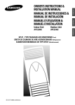
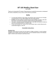
1
AP50Q0C Series AP55Q0C Series AP55Q2C Series AP50Q0D Series AP55Q0D Series AP55Q2D Series Air Conditioner user & installation manual imagine the possibilities Thank you for purchasing this Samsung product. To receive more complete service, please register your product at www.samsung.com/register E A DB98-32201A(6) AP50Q0C_IBIM_E 32201A(6).indd 35 2011-09-21 오후 12:21:06 Register your product at www.samsung.com/register Safety Precautions The following safety precautions must be taken when using your air conditioner. WARNING During operation • Risk of electric shock can cause injury or death. • Disconnect all remote electric power supplies before servicing, installing or cleaning. • This must be done by the manufacturer or its service agent or a similar qualified person in order to avoid a hazard. u Users of this product are cautioned not to attempt repair of this product at their own discretion. Instead, they are requested to directly contact a designated service center or the outlet at which the product was purchased. u Never spill any kind of liquid into the unit. Should this happen, unplug or main switch off the unit and contact an authorized service center. u Do not insert anything between the air outlet blades because the inner fan may be damaged and could cause injury. Keep children away from the unit. u Do not place any obstacles in front of the unit. u Do not spray liquid of any kind into the indoor unit. Should this happen, switch off the breaker used for your air conditioner and contact your installation specialist. u Make sure that the unit is correctly ventilated at all times: Do not place clothing or other materials over it. u If the wireless remote control will not be used for a long time, remove the batteries. (If applicable) u When using a wireless remote control, the distance should not be more than 7 m from the air conditioner. (If applicable) Disposing of the unit u Before throwing out the device, it is necessary to pull back the battery cells and get rid of them safely for recycling reasons. u When you need to dispose of the unit, consult your dealer. If pipes are removed incorrectly, refrigerant may blow out and come into contact with your skin, causing injury. Releasing refrigerant into the atmosphere also damages the environments. u Please recycle or dispose of the packaging material for this product in an environmentally responsible manner. Others u Never store or ship the air conditioner upside down or sideways to avoid damage to the compressor. u The appliance is not intended for use by young children or infirm persons without supervision: Young children should be supervised to ensure that they do not play with the appliance. u Max current is measured according to IEC standard for safety and current is measured according to ISO standard for energy efficiency. E-2 AP50Q0C_IBIM_E 32201-5.indd 2 2011-05-26 오후 2:38:11 Contents u Preparing your air conditioner Safety Precautions . . . . . . . . . . . . . . . . . . . . . . . . . . . . . . . . . . . . . . . . . . . . . . . . . . . . . . . . . . . . . . . . . . . 2 View of the Unit . . . . . . . . . . . . . . . . . . . . . . . . . . . . . . . . . . . . . . . . . . . . . . . . . . . . . . . . . . . . . . . . . . . . . 4 Remote Control-Buttons . . . . . . . . . . . . . . . . . . . . . . . . . . . . . . . . . . . . . . . . . . . . . . . . . . . . . . . . . . . . . 5 Inserting the Remote Control Batteries . . . . . . . . . . . . . . . . . . . . . . . . . . . . . . . . . . . . . . . . . . . . . . 5 Getting Started . . . . . . . . . . . . . . . . . . . . . . . . . . . . . . . . . . . . . . . . . . . . . . . . . . . . . . . . . . . . . . . . . . . . . . 6 Operating Preparation . . . . . . . . . . . . . . . . . . . . . . . . . . . . . . . . . . . . . . . . . . . . . . . . . . . . . . . . . . . . . . . 6 u Operating your air conditioner Cooling Your Room . . . . . . . . . . . . . . . . . . . . . . . . . . . . . . . . . . . . . . . . . . . . . . . . . . . . . . . . . . . . . . . . . 7 Selecting the Automatic Operating Mode . . . . . . . . . . . . . . . . . . . . . . . . . . . . . . . . . . . . . . . . . . . 8 Changing the Room Temperature Quickly . . . . . . . . . . . . . . . . . . . . . . . . . . . . . . . . . . . . . . . . . . . 9 Cooling Distant Place . . . . . . . . . . . . . . . . . . . . . . . . . . . . . . . . . . . . . . . . . . . . . . . . . . . . . . . . . . . . . . . 10 Removing Excess Humidity . . . . . . . . . . . . . . . . . . . . . . . . . . . . . . . . . . . . . . . . . . . . . . . . . . . . . . . . . 11 Airing Your Room . . . . . . . . . . . . . . . . . . . . . . . . . . . . . . . . . . . . . . . . . . . . . . . . . . . . . . . . . . . . . . . . . . . 12 Selecting E. Saver Mode . . . . . . . . . . . . . . . . . . . . . . . . . . . . . . . . . . . . . . . . . . . . . . . . . . . . . . . . . . . . . 13 Adjusting the Air Flow Direction Vertically . . . . . . . . . . . . . . . . . . . . . . . . . . . . . . . . . . . . . . . . . . . 14 Adjusting the Air Flow Direction Horizontally . . . . . . . . . . . . . . . . . . . . . . . . . . . . . . . . . . . . . . . . 14 u Programming your air conditioner Setting the Off Timer . . . . . . . . . . . . . . . . . . . . . . . . . . . . . . . . . . . . . . . . . . . . . . . . . . . . . . . . . . . . . . . . 15 Other Function . . . . . . . . . . . . . . . . . . . . . . . . . . . . . . . . . . . . . . . . . . . . . . . . . . . . . . . . . . . . . . . . . . . . . . 16 u Recommendations for use Operating Recommendations . . . . . . . . . . . . . . . . . . . . . . . . . . . . . . . . . . . . . . . . . . . . . . . . . . . . . . . 16 Temperature and Humidity Ranges . . . . . . . . . . . . . . . . . . . . . . . . . . . . . . . . . . . . . . . . . . . . . . . . . . 17 Cleaning Your Air Conditioner . . . . . . . . . . . . . . . . . . . . . . . . . . . . . . . . . . . . . . . . . . . . . . . . . . . . . . . 17 Solving Common Problems . . . . . . . . . . . . . . . . . . . . . . . . . . . . . . . . . . . . . . . . . . . . . . . . . . . . . . . . . . 18 u Technical specifications Technical Specifications . . . . . . . . . . . . . . . . . . . . . . . . . . . . . . . . . . . . . . . . . . . . . . . . . . . . . . . . . . . . . 19 u Installation part Accessory Parts List . . . . . . . . . . . . . . . . . . . . . . . . . . . . . . . . . . . . . . . . . . . . . . . . . . . . . . . . . . . . . . . . . . 20 Selection of Installation Place . . . . . . . . . . . . . . . . . . . . . . . . . . . . . . . . . . . . . . . . . . . . . . . . . . . . . . . . 21 Electrical Work . . . . . . . . . . . . . . . . . . . . . . . . . . . . . . . . . . . . . . . . . . . . . . . . . . . . . . . . . . . . . . . . . . . . . . 22 Installation Procedures . . . . . . . . . . . . . . . . . . . . . . . . . . . . . . . . . . . . . . . . . . . . . . . . . . . . . . . . . . . . . . 24 Connection of Refrigerant Piping . . . . . . . . . . . . . . . . . . . . . . . . . . . . . . . . . . . . . . . . . . . . . . . . . . . . 25 Drilling a Hole in the Wall . . . . . . . . . . . . . . . . . . . . . . . . . . . . . . . . . . . . . . . . . . . . . . . . . . . . . . . . . . . . 26 Drain Hose . . . . . . . . . . . . . . . . . . . . . . . . . . . . . . . . . . . . . . . . . . . . . . . . . . . . . . . . . . . . . . . . . . . . . . . . . . 26 Connecting the Pipe . . . . . . . . . . . . . . . . . . . . . . . . . . . . . . . . . . . . . . . . . . . . . . . . . . . . . . . . . . . . . . . . . 26 Air Purge . . . . . . . . . . . . . . . . . . . . . . . . . . . . . . . . . . . . . . . . . . . . . . . . . . . . . . . . . . . . . . . . . . . . . . . . . . . . 27 Refrigerant Charging . . . . . . . . . . . . . . . . . . . . . . . . . . . . . . . . . . . . . . . . . . . . . . . . . . . . . . . . . . . . . . . . 28 Check and Test Operation . . . . . . . . . . . . . . . . . . . . . . . . . . . . . . . . . . . . . . . . . . . . . . . . . . . . . . . . . . . 29 u Packing and unpacking guide Packing and Unpacking Guide . . . . . . . . . . . . . . . . . . . . . . . . . . . . . . . . . . . . . . . . . . . . . . . . . . . . . . . 31 u How to connect your extended power cables . . . . . . . . . . . . . . . . . . . . . . . . . . . . . . . . . . . 33 E-3 AP50Q0C_IBIM_E 32201-5.indd 3 2011-05-26 오후 2:38:11 View of the Unit Indoor Unit Air flow blades (up/down orientation) Air flow blades (right/left orientation) Air outlet Remote control holder Air filter To open the grille u Hold the upper part of the grille, then pull it slightly forward. Air inlet Control Panel You can operate the air conditioner with the control panel when you do not wish to or cannot operate the air conditioner with the remote control. Using the control panel, you can adapt the On/Off, temperature, fan speed, operation mode and air swing setting to your specific requirements. Timer indicator Operating mode indicators (Cool, Dry, Fan, Auto) Remote control sensor Lock function indicator Turbo function indicator Set temperature Indoor temperature E. Saver indicator Outdoor operating indicator On/Off button Long function indicator Fan speed Temperature adjustment buttons Fan speed adjustment button E. Saver button Air Swing button E-4 AP50Q0C_IBIM_E 32201-5.indd 4 2011-05-26 오후 2:38:12 Remote Control-Buttons All air conditioner features except Lock function and E. Saver mode can be controlled from your seat by using the remote control. You must operate the Turbo, Long function and Off Timer with the remote control. Temperature adjustment buttons Air flow swing buttons Operation mode selection button (Cool, Auto, Dry, Fan) Off Timer button Turbo/Long function button Fan speed adjustment button On/Off button Inserting the Remote Control Batteries You must insert or replace the remote control batteries when : u You purchase the air conditioner u The remote control does not work correctly Noteu Use two AAA, LR03 1.5V batteries. u Do not use old batteries or different kinds of batteries together. u Batteries may be completely discharged after 12 months, even if they have not actually been used. 1 Push the battery cover on the rear of the remote control with your thumb in the direction of the arrow and remove it. 2 Insert the two batteries, taking care to respect the polarities : u + on the batt ery with + on the remote control. u - on the battery with - on the remote control. 3 Close the cover by sliding it back until it clicks into place. E-5 AP50Q0C_IBIM_E 32201-5.indd 5 2011-05-26 오후 2:38:13 Getting Started You have just purchased a floor stand type air conditioner and it has been installed by your installation specialist. Your Manual contains valuable information on using your air conditioner. Please take the time to read it as it will help you take full advantage of the unit’s features. The booklet is organized as follows. u The following figures are shown on pages from 4 to 5 : - Indoor unit - Remote control(buttons and display) They will help you find the buttons and understand the symbols displayed. u In the manual, you will find a series of step-by-step procedures for each function available. The illustrations in the step-by-step procedures use three different symbols: PRESS PUSH HOLD DOWN For the... The illustrations are... Remote control In the upper part. Unit itself In the lower part. Operating Preparation Look around the indoor and outdoor units. Confirm if any obstacles that may prevent the air flow are present near the air conditioner. Turn the power switch on. IMPORTANT T o operate the unit, the power switch is fitted to the wall and should be set to ON. E-6 AP50Q0C_IBIM_E 32201-5.indd 6 2011-05-26 오후 2:38:13 Cooling Your Room You must select the Cool mode if you wish to adjust the : Cooling temperature Fan speed when cooling 1 If necessary, press the (On/Off) button. Result: u The power indicator on the control panel comes on. u The indoor unit beeps. u The air conditioner starts up in the Cool mode. IMPORTANT The air conditioner is fitted with a protection mechanism to prevent the unit from being damaged when it is started immediately after being: Switched on Stopped lt will start up normally after three minutes. 2 If the is not displayed on the control panel, press the button on the remote control one or more times until it appears. Result: u The indoor unit beeps each time you press the Note u The air conditioner runs in the Cool mode. button. You can change modes at any time. 3 To adjust the temperature, press the buttons on the remote buttons on the control panel one or more times control or until the required temperature is displayed. Possible temperatures are between 18°C and 30°C inclusive. Result: u Each time you press the buttons: - The temperature is adjusted by 1°C. - The indoor unit beeps. u The air conditioner starts cooling, provided that the room temperature is higher than the selected temperature. u If the room temperature reaches the set temperature, the air conditioner stops cooling, but the fan is still operating. 4 Select the fan speed by pressing the button on the remote button one or more times until the required setting control or is displayed : Automatic(rotated : ) Low High Turbo Result: Each time you press the button, the indoor unit beeps. 5 To control the direction of the air flow, refer to page 14. AP50Q0C_IBIM_E 32201-5.indd 7 E-7 2011-05-26 오후 2:38:15 Selecting the Automatic Operating Mode You can start the air conditioner in the Automatic mode from your remote control. In the Automatic mode, the temperature and the optimum fan speed is selected automatically. 1 If necessary, press the Result: (On/Off) button. u The power indicator on the control panel comes on. u The indoor unit beeps. u The air conditioner starts up in the Cool mode. The air conditioner is fitted with a protection mechanism IMPORTANT to prevent the unit from being damaged when it is started immediately after being: Switched on Stopped lt will start up normally after three minutes. 2 If the is not displayed on the control panel, press the button on the remote control one or more times until it appears. Result: u The indoor unit beeps each time you press the button. u The air conditioner runs in the Auto mode. Note u You can change modes at any time. 3 To control the direction of the air flow, refer to page 14. Note To adjust the temperature, press the buttons. The temperature will be adjusted and the mode will be changed with the Cool mode. E-8 AP50Q0C_IBIM_E 32201-5.indd 8 2011-05-26 오후 2:38:16 Changing the Room Temperature Quickly The Turbo function is used to cool your room as quickly as possible. Example : ou have just come home and find that the room is very Y hot. You wish to cool it down as quickly as possible. The Turbo function operates for 30 minutes with the maximum setting before returning automatically to the mode and temperature previously selected. 1 If necessary, press the Result: (On/Off) button. u The power indicator on the control panel comes on. u The indoor unit beeps. u The air conditioner starts up in the Cool mode. The air conditioner is fitted with a protection mechanism IMPORTANT to prevent the unit from being damaged when it is started immediately after being: Switched on Stopped lt will start up normally after three minutes. 2 Press the Result: button. u The air conditioner cools the room as quickly as possible. u The temperature and fan settings are adjusted automatically. u After 30 minutes, the air conditioner is reset automatically to the previous mode, temperature and fan setting. But, if you press the button in the Dry or the Fan mode that is changed with the Auto mode automatically. 3 If you wish to stop the Turbo function before the end of 30-minute period, press the button twice. Result: u The air conditioner is reset automatically to the previous mode, temperature and fan settings. 4 To control the direction of the air flow, refer to page 14. E-9 AP50Q0C_IBIM_E 32201-5.indd 9 2011-05-26 오후 2:38:16 Cooling Distant Place The Long function is used to cool your room as far as possible. In the Long mode, the up/down orientation of air flow and fan speed are selected automatically. 1 If necessary, press the Result: (On/Off) button. u The power indicator on the control panel comes on. u The indoor unit beeps. u The air conditioner starts up in the Cool mode. The air conditioner is fitted with a protection mechanism IMPORTANT to prevent the unit from being damaged when it is started immediately after being: Switched on Stopped lt will start up normally after three minutes. 2 Press the Result: button twice. u The air conditioner cools the room as far as possible. u The fan settings are adjusted automatically. u If you press the button in the Dry or the Fan mode that is changed with the Auto mode automatically. 3 To adjust the temperature, press the buttons one or more times until the required temperature is displayed. Possible temperatures are between 18°C and 30°C inclusive. Result: u Each time you press the buttons: - The temperature is adjusted by 1°C. - The indoor unit beeps. 4 If you wish to stop the Long function, press the again. Result: button u The air conditioner is reset automatically to the previous mode, temperature and fan settings. 5 To control the direction of the air flow horizontally, refer to page 14. E-10 AP50Q0C_IBIM_E 32201-5.indd 10 2011-05-26 오후 2:38:17 Removing Excess Humidity If the atmosphere in your room is very humid or damp, you can remove excess humidity without lowering the room temperature too much. 1 If necessary, press the Result: (On/Off) button. u The power indicator on the control panel comes on. u The indoor unit beeps. u The air conditioner starts up in the Cool mode. IMPORTANT The air conditioner is fitted with a protection mechanism to prevent the unit from being damaged when it is started immediately after being: Switched on Stopped lt will start up normally after three minutes. 2 If the is not displayed on the control panel, press the button on the remote control one or more times until it appears. Result: u The indoor unit beeps each time you press the button. u The air conditioner runs in the Dry mode. Note You can change modes at any time. 3 To adjust the temperature, press the buttons one or more times until the required temperature is displayed. Possible temperatures are between 18°C and 30°C inclusive. Result: u Each time you press the buttons: - The temperature is adjusted by 1°C. - The indoor unit beeps. u The air conditioner starts removing the excess humidity; the quantity of air is adjusted automatically. 4 To control the direction of the air flow, refer to page 14. E-11 AP50Q0C_IBIM_E 32201-5.indd 11 2011-05-26 오후 2:38:18 Airing Your Room If the atmosphere in your room is stale, you can air the room using the Fan feature. 1 If necessary, press the Result: (On/Off) button. u The power indicator on the control panel comes on. u The indoor unit beeps. u The air conditioner starts up in the Cool mode. The air conditioner is fitted with a protection mechanism IMPORTANT to prevent the unit from being damaged when it is started immediately after being: Switched on Stopped lt will start up normally after three minutes. 2 If the is not displayed on the control panel, press the button on the remote control one or more times until it appears. Result: u The indoor unit beeps each time you press the button. u The air conditioner runs in the Fan mode. Note You can change modes at any time. 3 Select the fan speed by pressing the button one or more times until the required setting is displayed: Low High Turbo Result: Each time you press the button, the indoor unit beeps. 4 To control the direction of the air flow, refer to page 14. Note To adjust the temperature, press the buttons. The temperature will be adjusted and the mode will be changed with the Cool mode. E-12 AP50Q0C_IBIM_E 32201-5.indd 12 2011-05-26 오후 2:38:19 Selecting E. Saver Mode If your wish to save energy when using the control panel of your air conditioner, select the E. Saver mode with the E. Saver button. 1 If necessary, press the Result: (On/Off) button. u The power indicator on the control panel comes on. u The indoor unit beeps. u The air conditioner starts up in the Cool mode. The air conditioner is fitted with a protection mechanism IMPORTANT to prevent the unit from being damaged when it is started immediately after being: Switched on Stopped lt will start up normally after three minutes. 2 Press the Result: button on the control panel. u The indoor unit beeps. u The air conditioner runs in the E. Saver mode. u The outer air flow blade moves up and down. 3 To adjust the temperature, press the buttons one or more times until the required temperature is displayed. Possible temperatures are between 18°C and 30°C inclusive. NoteYou can adjust the temperature only when the air conditioner runs in the Cool mode. 4 To select the fan speed, press the until the required setting is displayed. button one or more times 5 To control the direction of the air flow, refer to page 14. E-13 AP50Q0C_IBIM_E 32201-5.indd 13 2011-05-26 오후 2:38:20 Adjusting the Air Flow Direction Vertically Depending on the position of the indoor unit in your room, you can adjust the position of the outer air flow blade on the upper part of the unit, thus increasing the efficiency of the air conditioner. 1 Press the button. Result: The outer blade moves up and down. RECOMMENDATION When... Adjust the blade to face... Cooling Upwards. 2 To stop the blade moving up and down, press the again. button Adjusting the Air Flow Direction Horizontally There are two sets of air flow blades. Just as the outer air flow blade can be adjusted vertically, the inner blade can be adjusted horizontally. 1 Press the button. Result: The inner blade moves right and left. 2 To stop the blade moving right and left, press the again. button E-14 AP50Q0C_IBIM_E 32201-5.indd 14 2011-05-26 오후 2:38:21 Setting the Off Timer The Off Timer enables you to switch off the air conditioner automatically after a given period of time. You can set the period of time from 1 to 8 hours. You can select the Off Timer only when the air conditioner is on. To set the operating time, press the button one or more times until the required time is displayed. Possible time is between 1 hour and 8 hours inclusive. Result: u After blinking of the timer indicator for 5 seconds, it will be changed to temperature setting. u The air conditioner will switch off automatically after the set time and the Off Timer indicator disappears. Note You can see or change the setting mode and/or the button or the temperature by pressing the buttons after setting the Off Timer. To Cancel the Off Timer Press the disappears. one or more times until the Off Timer indicator E-15 AP50Q0C_IBIM_E 32201-5.indd 15 2011-05-26 오후 2:38:22 Other Function You can use the Lock function on the control panel of the indoor unit. 1 Press the buttons simultaneously for 3 seconds. Result: u indicates on the control panel. u The control panel is locked. NoteYou can use the remote control even if the control panel is locked. 2 To cancel the Lock function, press the simultaneously for 3 seconds once again. buttons Operating Recommendations Here are a few recommendations that you should follow when using your air conditioner. Topic Recommendation Power failure If a power failure occurs when the air conditioner is operating, the unit is switched off. When the power returns, you must press the (On/Off ) button to restart it. E-16 AP50Q0C_IBIM_E 32201-5.indd 16 2011-05-26 오후 2:38:22 Temperature and Humidity Ranges The following table indicates the temperature and humidity ranges, within which the air conditioner can be used. If the air conditioner is used at... Then... High temperature The automatic protection feature may be triggered and the air conditioner stopped. Low temperature A water leakage or some other malfunction may happen if the heat exchanger freezes. High humidity levels Water may condense on and drip from the surface of the indoor unit if it is used for a long periods. Mode Outdoor Temperature Indoor Temperature Indoor Humidity Cooling 21°C to 54°C approx. 18°C to 32°C approx. 80% or less Drying 18°C to 54°C approx. 18°C to 32°C approx. - g If the cooling operation is used at over 33°C(indoor temperature), it does not cool at its full capacity. Cleaning Your Air Conditioner For the best use of your air conditioner, you must clean it every other week regularly to remove the dust that accumulates on the air filter. Before cleaning your air conditioner, ensure that you IMPORTANT have switched off the breaker for the unit. 1 Open the front grille, then pull out the air filter. 2 Remove all dust on the air filter with a vacuum cleaner or brush. 3 When you have finished, insert the air filter into the original position and close the front grille. 4 Clean the unit with a damp cloth and mild detergent (do NOT use benzene, solvents or other chemicals). Note If you have not used the air conditioner for a long period of time, set the fan going for 3 to 4 hours to dry the inside of the air conditioner thoroughly. E-17 AP50Q0C_IBIM_E 32201-5.indd 17 2011-05-26 오후 2:38:23 Solving Common Problems Before contacting the after-sales service, perform the following simple checks. They may save you the time and expense of an unnecessary call. Problem Explanation/Solution The air conditioner does not operate at all Check that the breaker used for the air conditioner is switched on. Check that the indoor unit is turned on; if necessary press the (On/Off ) button on the remote control. Check whether the Timer indicator on the indoor unit is switched on. If so: - Wait until the switch-on time is reached and the air conditioner starts up automatically. - Cancel the Timer (see page 15 for further details) The air conditioner does not operate with the remote control Check that there are no obstacles between you and the indoor unit. Check the remote control batteries. Check that you are close enough to the indoor unit (7 metres /yards or less). No beep is heard when you press the (On/Off ) button on the remote control Check that you are pointing the remote control at the remote control sensor of the indoor unit. Replace the remote control batteries if necessary. The air conditioner does not cool Check that the correct operating mode has been selected (Cool, Auto). The room temperature may be too low or too high. Dust may be blocking the air filter guard; refer to page 18 for cleaning instructions. Check that there is no obstacle in front of the outdoor unit. The fan speed does not change when you press the button Check that the operating mode is set to Cool or Fan ; in the Auto, Turbo, Long and Dry mode, the fan speed is controlled automatically. The air flow direction does not Check that the air conditioner has been switched on; if necessary, change when you press the press the (On/Off ) button on the remote control. button or The Timer is not correctly triggered Check that the timer has been programmed correctly; see page 15. Odour is permeated in the room during air conditioning Air the room. E-18 AP50Q0C_IBIM_E 32201-5.indd 18 2011-05-26 오후 2:38:23 Technical Specifications Model Power Supply AP50Q0C Series AP50Q0D Series 3N~, 380V, 50Hz AP55Q0C Series AP55Q0D Series 3~, 220V, 60Hz AP55Q2C Series AP55Q2D Series 3N~, 380V, 60Hz . l E-19 AP50Q0C_IBIM_E 32201-5.indd 19 2011-05-26 오후 4:07:43 Be sure to read the manual carefully to ensure sufficient realization of the excellent performance of the unit. Be sure to drill a hole in the wall necessary for installation before attempting to install the unit. After completion of installation, be sure to perform a test operation of the unit to check for any problem, and then deliver the unit to the customer if the test results are acceptable. After completion of test operation, hand over the manual and warranty card to the customer. As the installation work requires special skill, be sure to request a qualified dealer to take care of the installation of your unit; the user should not attempt to install his/her unit by himself/herself. Do not attach any electric heating device or electric heater to the unit. Do not attempt to disassemble or modify the unit by yourself. (It may cause machine trouble, electric shock or fire.) Accessory Parts List No. Part Name Remarks No. Part Name 1 Drain hose 7 Cable tie 2 Connecting pipe 8 Putty 9 Pipe band 3 4 ø9.52mm (3/8 inch) Connecting pipe Remarks ø19.05mm (3/4 inch) Connection wiring (4 strand) Piping box Piping box 10 Cover hole 11 Screw 5 Insulation for piping 6 Finishing tape g The type and quantity may differ depending on the specifications. E-20 AP50Q0C_IBIM_E 32201-5.indd 20 2011-05-26 오후 2:38:24 Selection of Installation Place Indoor Unit Top view Install the unit at a place close to the wall facing the outside as it is necessary to perform piping connection with the outdoor unit. - It is effective to install the unit at a window side to ensure uniform distribution of indoor temperature. Install the unit at a place where there is no obstacle against the wind around the air inlet and air outlet. Install the unit horizontally at a stable, rigid place. (When installing the unit at a place subjected to oscillation, noise may occur.) Avoid a place near the door which is frequented by people. Avoid a place subject to direct sunlight. Above 50cm Side view Above 20cm Outdoor Unit Do not install the outdoor unit on a wood palette. Fix the outdoor unit completely to the base surface with anchor bolts. The manufacturer is not responsible for the damage occurred by not keeping standard of the installation. Above 100cm A place free from the risk of combustible gas leakage. A place which can bear the weight of the unit. A place which can bear the fixing strength of the outdoor unit. Avoid a place subject to oil (including machine oil). Avoid a saline place. Avoid a place subject to sulfide gas (hot spring zone). (When installing the unit at such special environmental conditions, it may cause machine trouble. When it is unavoidable to use such places, It requires special maintenance.) A place where the discharge air and noise of the outdoor unit do not disturb the neighborhood. (Take special care not to cause any inconvenience to your neighbors when installing the unit on the borderline with your neighborhood.) A place where strong wind does not head against the air outlet of the outdoor unit. (If a strong wind heads directly against the air outlet at the time of cooling operation, a safety device can be operated.) Do not install the outdoor unit at an unstable place such as outer wall of an apartment or building. The outdoor unit may fall down, causing severe personal or property damage or loss. Wall Air outlet If there is any unavoidable reason to install the unit at such a place, take the following measures against the wind; 1. When installing the unit at a roadside concentrated with buildings, install it parallel with the road. 2. Install the unit so that the air outlet faces toward the wall at a place such as rooftop, which may be subjected to strong wind. Strong wind Roof top The outdoor unit should be installed in accordance with the service space. Above 60cm Above 50cm Above 50cm Above 30cm Space for piping and wiring The air inlet faces toward the wall. Above 30cm Space for piping and wiring Above 60cm The air outlet faces towards the wall. E-21 AP50Q0C_IBIM_E 32201-5.indd 21 2011-05-26 오후 2:38:24 Electrical Work The electrical work should be performed by a specialist qualified for the work. Use the three phase power supply, and be sure to install the sub power distribution board for exclusive use with the unit(separately purchased by the user). Do not connect multiple plugs to an outlet at once because it can cause a drop in voltage, resulting in poor performance of the automatic control circuit. Be sure to install circuit breaker (Extra purchased by the user). Be sure to connect the grounding wire. If the terminal is loose, fire may occur by arc. If the terminal is connected too firmly, the terminal may be damaged. Screw M3 M3.5 M4 M5 M6 Tightening torque (kgf·cm) 5.0~6.0 8.0~10.0 12.0~15.0 20.0~25.0 25.0~30.0 Electric power specification MODEL Power Ampere of breaker Knife switch Switch Fuse AP50Q0C/AP50Q0D Series AP55Q0C/AP55Q0D Series AP55Q2C/AP55Q2D Series 3N~, 380V, 50Hz 3~, 220V, 60Hz 3N~, 380V, 60Hz 50 A 50 A 50 A 30 A 30 A 30 A 30 A 30 A 30 A Size of grounding wire 2.0mm2 2.0mm2 2.0mm2 Min. size of electric wires from/ to the indoor/outdoor unit 0.75mm2 0.75mm2 0.75mm2 5.5/3.5mm2 5.5/3.5mm2 5.5/3.5mm2 Size of electric input wires Be sure to use the wires, and switches or fuses of power distribution board are qualified and fulfill the specification. Be sure to install knife switch or circuit breaker on the power distribution board. The electrical and grounding work should be performed as per “ technical specifications of electrical facilities ” and “ specifications of internal wiring ”. Be sure to connect the main electrical input wires with bolted connectors using compressed terminal. E-22 AP50Q0C_IBIM_E 32201-5.indd 22 2011-05-26 오후 2:38:24 AP50Q0C/AP50Q0D/AP55Q2C/AP55Q2D Series When connecting 3Phase 4wires 380V AC 1. Remove the cover of electric box on side panel of the outdoor unit. 2. AP50Q0C Series Connect the electric input wires (R,S,T,N) to each terminal (R,S,T,N) of the electric box on AP50Q0D Series the outdoor unit respectively. (Input wires are purchased by the user separately.) AP55Q2C Series Connect the electric input wires (R,S,T,N) to each terminal (L1,L2,L3,N) of the electric box AP55Q2D Series on the outdoor unit respectively. (Input wires are purchased by the user separately.) 3. Connect the electric wires to each terminal on the indoor and outdoor unit respectively. AP50Q0C/AP50Q0D Series AP55Q2C/AP55Q2D Series OUTDOOR SIDE Power terminals on the outdoor unit OUTDOOR SIDE Knife switch or Power terminals on the outdoor unit automatic circuit breaker Knife switch or automatic circuit breaker Brown Blue Blue Brown Black Black Indoor/outdoor unit connecting wire Indoor/outdoor unit connecting wire Electric input wires Electric input wires AP55Q0C/AP55Q0D Series When connecting 3Phase 3wires 220V AC 1. Remove the cover of electric box on side panel of the outdoor unit. 2. Connect the electric input wires (R,S,T) to each terminal (L1,L2,L3) of the electric box on the outdoor unit respectively. (Input wires are purchased by the user separately.) 3. Connect the electric wires to each terminal on the indoor and outdoor unit respectively. OUTDOOR SIDE Power terminals on the outdoor unit Blue Brown Knife switch or automatic circuit breaker Black Indoor/outdoor unit connecting wire Electric input wires E-23 AP50Q0C_IBIM_E 32201-5.indd 23 2011-05-26 오후 2:38:25 Installation Procedures 1. Open the front panel, and remove the flare nut. 2. Bend the connection pipe to an appropriate length using the spring bender depending upon the installation place. - Allowable pipe length : Maximum 25m - Allowable pipe drop distance : Maximum 15m - Make no more than ten bending points on the pipe When the pipe length is in excess of the standard pipe length of 5m, add the refrigerant (R22) of 70g for each additional 1m. Additional Refrigerant Example:15m pipe length, additional refrigerant to be charged is (15m-5m)X70g/m=700g I f the pipe is lengthened, the performance of the unit is degraded, and the service life is shortened. Therefore, the pipe length should be as short as possible (less than 25m). Indoor unit Indoor unit Indoor unit Fix the pipe Less than 6m Outdoor unit Less than 15m Less than 15m Outdoor unit S-TRAP Outdoor unit Fix the pipe (Every 6m) 3. Install the high pressure pipe to the heat exchanger liquid pipe, and the low pressure pipe to the heat exchanger gas pipe respectively using the flare nut, taking care not to cause any leakage of refrigerant. 4. Be sure to insulate the pipe with appropriate insulation material. 5. Insert the drain hose into the drain pipe, and connect them by tying them to the cable tie to prevent any water leakage. 6. After completion of the installation, check the connecting area for any gas leakage. 7. Wind a finish tape when the wiring of the refrigerant pipe, the unit, and the drain piping are completed. Indoor unit checking area Outdoor unit checking area E-24 AP50Q0C_IBIM_E 32201-5.indd 24 2011-05-26 오후 2:38:25 Connection of Refrigerant Piping When installing, make sure there is no leakage. When recovering the refrigerant, ground the compressor first before removing the connection pipe. If the refrigerant pipe is not properly connected and the compressor works with the service valve open, the pipe inhales the air and it makes the pressure inside of the refrigerant cycle abnormally high. It may cause explosion and injury. Flare Processing 1. Cut the pipe using the pipe cutter. 90 Oblique Roughness Burr 2. Insert the flare nut into the pipe, and then perform the flare processing. Outer Diameter A(mm) 9.52mm 1.8 19.05mm 2.2 A Pipe Bending 1. Perform bending of the pipe using the bender which has a specified bending radius. 2. Be sure to take full care to perform bending of the pipe successfully at one time. Bending and unbending the pipe more than twice makes the bending work increasingly difficult. 3. You may use the spring inserted into the gas pipe instead of the bender to bend the pipe. 4. When you bend the pipe using the spring, hold the pipe with both hands to prevent any distortion, and secure a minimum bending radius of more than 100mm. Spring Tightening of Connection Parts Align the center of the connection piping, and tighten the flare nut by turning it with hand. Then tighten it again using the torque wrench in the direction as shown in the figure. Outer Diameter 9.52mm 19.05mm Torque (kgf•cm) 250~280 990~1210 Remarks E-25 AP50Q0C_IBIM_E 32201-5.indd 25 2011-05-26 오후 2:38:25 Drilling a Hole in the Wall Drill a hole of 70mm in diameter to the outside. The drilling should be done at a distance of less than 150mm from the floor facing the indoor unit. ø70mm Less than 150mm Drain Hose Extend the drain hose to the drain hose connected to the drain pan, and fix it with the tape or a cable-tie to prevent separation. Then make a covering of it so that water cannot flow outwardly. Piping Material Vinyl Chloride (Outer diameter ø16mm) Insulator Foamed Polyethylene Drain pan Band Drain hose Insulation Indoor and outdoor unit connection 1. A s the draining is of natural drain type, make the drain hose direct downward. 2. If there is any foreign substance in the drain plate, it may clog the drain pipe. Therefore, be sure to remove the foreign substance inside after installation. 3. After completion of installation, be sure to pour water into the drain pan, and then check the draining condition.(There is no problem in draining when the draining is completed within 20 seconds.) Connecting the Pipe The piping of this unit can be connected to the right, left, and rear side. When you hit the area for piping connection slightly with a hammer, a hole is made. After connecting the piping and drain hose, insert the rubber cap as shown in the figure. Holes for piping connection (2 points) E-26 Cover hole The shape of hole may vary with the models. AP50Q0C_IBIM_E 32201-5.indd 26 2011-05-26 오후 2:38:26 Air Purge Be sure that all valve cocks are closed. The air in the indoor unit and in the pipe must be purged. If air remains in the refrigeration pipes, it will affect the compressor, reduce cooling capacity and could lead to a malfunction. Use Vacuum Pump as shown at the figure. 1. Connect each assembly pipe to the appropriate valve on the outdoor unit and tighten the flare nut. 2. Connect the charging hose of low pressure side of manifold gauge to the packed valve having a service port as shown at the figure. 3. Open the valve of the low pressure side of manifold gauge counter-clockwise. 4. Purge the air from the system using vacuum pump for about 30 minutes. - Close the valve of the low pressure side of manifold gauge clockwise. - Make sure that pressure gauge show -0.1MPa(-76cmHg) after about 30 minutes. - This procedure is very important in order to avoid gas leak. - Turn off the vacuum pump. - Remove the hose of the low pressure side of manifold gauge. 5. Set valve cork of both liquid side and gas side of packed valve to the open position. 6. Mount the valve stem nuts and the service port cap to the valve, and tighten them at the torque of 183kgf•cm with a torque wrench. 7. Check for gas leakage. - At this time, especially check for gas leakage from the 3-way valve’s stem nuts, and from the service port cap. Gas pipe side OUTDOOR UNIT Indoor unit D Liquid pipe side Liquid pipe side A B Flare nut Valve cock Cap 3-way valve 3-way valve Vacuum Pump C Gas pipe side B A Outdoor unit Needle valve cap E-27 AP50Q0C_IBIM_E 32201-5.indd 27 2011-05-26 오후 2:38:26 Refrigerant Charging Air purge(at the time of new installation only) Close the gas pipe side valve by turning it clockwise. Connect the pressure gauge to the low pressure side service valve, and then open the gas pipe side valve again. Connect it to the refrigerant filling tank. OUTDOOR UNIT Gas pipe side Liquid pipe side Start cooling operation. Check the pressure of the pressure gauge. Check whether the low pressure side is within the range of 4.5~5.6kg/cm2G (outside temperature 35°C). Open the tank and refill the refrigerant until arriving at the proper pressure. (Refill the refrigerant slowly checking the pressure.) Stop operation. Close the gas pipe side valve, and loosen the pressure gauge connected. Then open the gas pipe side valve again. Tighten the cap of each valve using a specified tool. Always use R22 refrigerant to avoid damage of the unit or an explosion. Must keep the quantity of refrigerant by using a balance. Do not use a manometer or not depend on your experiences. E-28 AP50Q0C_IBIM_E 32201-5.indd 28 2011-05-26 오후 2:38:26 Check and Test Operation Check Be sure to check the following again after completion of installation. 1. Check the piping connection area for any gas leakage. Outdoor connection area Indoor connection area 2. Is the drain hose properly connected? Drain hose 3. Is the insulation of the piping in good condition? Indoor and outdoor unit connection 4. Is grounding properly made? Insulation E-29 AP50Q0C_IBIM_E 32201-5.indd 29 2011-05-26 오후 2:38:26 Check and Test Operation (Continued) Test Operation After checking, read the manual carefully, and perform a test operation. Then deliver the unit to the customer. (When delivering the unit, be sure to read carefully and follow the contents of the manual.) 1. Be sure to check whether the service valve is opened before attempting to perform the test operation. 2. Never attempt to start test operation by force pressing the electronic contactor as it is very dangerous. (This is very dangerous as the protective device does not work.) 3. Be sure to perform the test operation after installation. It is easy to start the test operation in winter if you increase the sensor temperature to 23°C ~ 25°C by holding the indoor temperature sensor. (Cooling operation) When the outdoor temperature is below zero, do not test operation for more than 3 minutes. Otherwise, the compressor will be damaged. Temperature sensor E-30 AP50Q0C_IBIM_E 32201-5.indd 30 2011-05-26 오후 2:38:26 Packing and Unpacking Guide Indoor unit Cushion-top Packing case Cushion-mid Indoor unit Cushion-bottom Packing the unit as below procedure 1. Put the indoor unit onto the cushion-bottom. 2. Assemble cushion-mid of indoor unit. 3. Put the cushion-top onto the indoor unit. 4. Put the packing case from the top of set. 5. Seal the packing case. Unpacking the unit as below procedure 1. Take out the packing case from the set. 2. Take out the cushion-top. 3. Take out the cushion-mid. 4. Move the set from the cushion-bottom. E-31 AP50Q0C_IBIM_E 32201-5.indd 31 2011-05-26 오후 2:38:27 Packing and Unpacking Guide (Continued) Outdoor unit Cushion-top Outdoor unit Packing case 4 screws Wood palette Packing the unit as below procedure 1. Fix the outdoor unit and the wood palette by 4 screws. 2. Put the cushion-top onto the outdoor unit. 3. Put the packing case from the top of set. 4. Seal the packing case. Unpacking the unit as below procedure 1. Take out the packing case from the set. 2. Take out the cushion-top. 3. Unscrew 4 screws from the wood palette and then move the set. E-32 AP50Q0C_IBIM_E 32201-5.indd 32 2011-05-26 오후 2:38:27 How to connect your extended power cables ※ Items to prepare (compressor and insulation tape should be prepared by an installation technician.) Tools Spec Crimping plier Connection sleeve (mm) Insulation tape Contraction tube (mm) MH-14 20xØ7.0(HxOD) Width 18mm 50xØ8.0(LxOD) Shape 1. As shown in the figure, peel off the shields from the rubber/wire of the power cable. - Peel off 20 mm of the wire shields of the tube installed already. (Unit: mm) Power cable (provided by us) 20 After peeling off the tube wire, you must insert a contraction tube. 20 20 60 120 180 Wire tube power cable 20 2. Insert both sides of core wire of the power cable into the connection sleeve. Connection sleeve 3. Using a compressor, compress the two points and flip it over and compress another two points in the same location. - The compression dimension should be 8.0. - After compressing it, pull both sides of the wire to make sure it is firmly pressed. Comp. dim. Compress it 4 times 5mm 4. Wrap it with the insulation tape twice and position your contraction tube in the middle of the insulation tape. 5. Apply heat to the contraction tube to contract it. 6. After tube contraction work is completed, wrap it with the insulation tape to finish. Insulation tape 40mm Contraction tube Insulation tape In case of extending the electric wire, please DO NOT use a round-shaped pressing socket. - Incomplete wire connections can cause electric shock or a fire E-33 AP50Q0C_IBIM_E 32201-5.indd 33 2011-05-26 오후 2:38:28 QUESTIONS OR COMMENTS? COUNTRY IRAN CALL OR VISIT US ONLINE AT 021-8255 www.samsung.com 800-SAMSUNG(726-7864) www.samsung.com KUWAIT 183-2255 www.samsung.com BAHRAIN 8000-4726 www.samsung.com 08000-726786 www.samsung.com OMAN EGYPT JORDAN MOROCCO SAUDI ARABIA TURKEY U.A.E AP50Q0C_IBIM_E 32201A(6).indd 34 800-22273 www.samsung.com 080 100 2255 www.samsung.com 9200-21230 www.samsung.com 444 77 11 www.samsung.com 800-SAMSUNG (726-7864) www.samsung.com 2011-09-21 오후 12:21:06