1
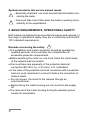
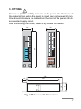
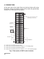
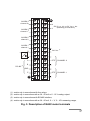
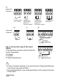
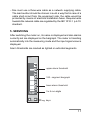
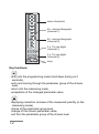
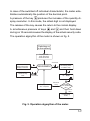
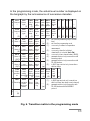
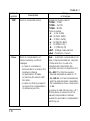
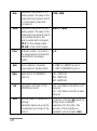
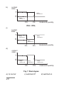
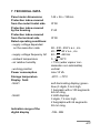
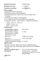
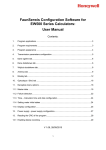
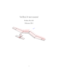
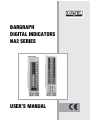
BARGRAPH DIGITAL INDICATORS NA2 SERIES USERS MANUAL BARGRAPH DIGITAL INDICATORS NA2 SERIES CONTENTS 2=CA 1. APPLICATION ....................................................................... 3 2. BASIC REQUIREMENTS, OPERATIONAL SAFETY ........... 4 3. FITTING ................................................................................. 5 4. CONNECTION ....................................................................... 6 5. SERVICING ........................................................................... 9 6. PROGRAMMING ................................................................. 12 7. TECHNICAL DATA .............................................................. 21 8. ORDERING PROCEDURE ................................................. 26 9. MAINTENANCE AND WARRANTY .................................... 27 ! " 1. APPLICATION NA2 series bargraph panel meters with digital and analog indications are destined to measure d.c. voltages and d.c. currents, temperature, resistance and other non-electrical quantities converted into electrical signals. They can realize additional functions such as: · overrun signalling of setting alarm values, · overrun signalling of the measuring range, · programmable resolution of the bargraph, · recalculation of the measured quantity into any arbitrary quantity on the base of an individual lineal characteristic y = ax + b, · conversion of the measured quantity into a current or voltage standard signal, · digital communication through the RS-485 interface, with the MODBUS protocol, · supply of two-wire object transducers (24 V) in the following measuring range executions: 0/4...20 mA, 0...1 V, 0...10 V. With the meter we deliver: · a warranty card, · 2 holders to fix the meter into a panel, · a service manual, · a service manual for execution with an interface, · a set of stickers with units. When unpacking the meter, please check whether the type and execution code on the data plate corresponds to the order. # Symbols located in this service manual meant: - Especially important, one must acquaint with this before con! necting the meter. ? - One must take note of this when the meter is working inconsistently to the expectations. 2. BASIC REQUIREMENTS, OPERATIONAL SAFETY NA2 meters are destined to be mounted into panels and cubicles. In the range of operational safety, they are in conformity with the IEC 1010 standard requirements. ! Remarks concerning the safety: · The installation and meter connection should be operated by qualified personel. One must take into consideration all accessible protection requirements. · Before switching the meter on, one must check the correctness of the network lead connection. · One must take care especially of the protection terminal connection IEC1010-1 p. 6.10 and p. 6.11.2 standard. · In the case of the protection terminal connection with a separate lead one must remember to connect it before the connection of network leads. · Do not connect the meter to the network through an auto-transformer. · Before taking the meter housing out one must turn the supply off. · The removal of the meter housing during the warranty period causes its cancellation. $ 3. FITTING ! Prepare a (34+0.6 x 137+1) mm hole in the panel. The thickness of the material from which the panel is made can not exceed 20 mm. One should introduce the meter from the front of the panel with disconnected supply circuit. After introducing the meter, fasten it by means of holders. 36 36 100 NA21 90 100 80 90 70 80 60 70 50 60 30 144 30 20 144 40 50 40 10 20 0 10 NA22 0 130 118 33 18 Fig. 1. Meter overall dimensions % 4. CONNECTION At the rear side of the meter there are terminal strips with screw terminals. Analog and digital outputs of the meter are galvanically isolated from other parts of the system. 30 15 29 14 N 28 13 L 230 V a.c., d.c. or 24 V a.c., d.c. (according to execution) 27 12 11 25 10 24 9 23 8 22 7 21 6 24V d.c. 4) + ALARM 1 channel 1 26 2) A 20 5 B 19 4 GND 18 3 E 17 2 16 1 + ALARM 2 channel 11) + RS-485 3) RTD CHANNEL 1 (1) - exists only in executions with two relays, (2) - exists only in executions with a 0/4...20 mA or 0...10 V analog output, (3) - exists only in executions with RS-485 interface, (4) - exists only in executions with a 0/4...20 mA, 0...1 V, 0...10 V measuring range. Fig. 2. Description of NA21 meter terminals & ALARM 2 channel 2 N L 2) A 230 V a.c., d.c. or 24 V a.c., d.c. (according to execution) 27 12 26 11 25 10 24 9 23 8 22 7 + ALARM 1 channel 1 29 14 28 13 21 6 20 5 B 19 4 GND 18 3 E 17 2 16 1 + ALARM 3 channel 11) 30 15 24V d.c. 4) + ALARM 4 channel 21) RTD CHANNEL 2 RTD CHANNEL 1 + RS-485 3) (1) - exists only in executions with four relays, (2) - exists only in executions with a 0/4...20 mA or 0...10 V analog output. (3) - exists only in executions with RS-485 interface, (4) - exists only in executions with a 0/4...20 mA, 0...1 V, 0...10V measuring range, Fig. 3. Description of NA22 meter terminals ' a) Channel 2 Channel 1 4 5 6 4 5 6 4 5 6 4 5 6 1 2 3 1 2 3 1 2 3 1 2 3 Thermocouple or -5...60 mV b) Resistance Potentiometer thermometer transmitter probe in a three-wire system Resistance thermometer probe in a two-wire system c) d) Channel 2 4 5 4 5 6 4 6 7 8 Channel 1 1 2 1 2 3 1 3 7 8 - + - + + I - U = 6 7 8 1 3 7 8 + I - 4 S Fig. 4. Connection way of the input signal: a/ temperature sensors and the potentiometric transmitter, b/ voltage, c/ current d/ object transducers. 2-wire transducer 3-wire transducer ! - In case of meters working in an environment of high perturbances one should use external filters. - It is recommended to use screened leads on the output and input of the meter. - One must use a three-wire cable as a network supplying cable. The lead section should be chosen in such a way that in case of a cable short-circuit from the equipment side, the cable would be protected by means of electrical installation fuses. Requirements towards the network cable are regulated by the IEC 1010-1 p.6.10. standard. 5. SERVICING After switching the meter on, its name is displayed and also alarms currently set are displayed on the bargraph. The meter is transiting automatically into the measuring mode and the input signal value is displayed. Alarm thresholds are marked as lighted or extincted segments NA21 100 90 80 upper alarm threshold 70 60 50 100 - segment bargraph 40 30 20 10 lower alarm threshold 0 3 x 5 mm digits keys 100 90 80 alarm threshold 70 60 50 64 - element bargraph (channel 1) 40 30 20 64 - element bargraph (channel 2) 10 0 NA22 3 x 7.5 mm digits (channel 1) 3 x 7.5 mm digits (channel 2) keys Key functions: · entry into the programming mode (hold down during ca 3 seconds), · entry and moving through the parameter group of the chosen level, · return into the measuring mode, · acceptation of the changed parameter value. · displaying resolution increase of the measured quantity (in the measuring mode), · choice of the parameter group level, · change of the chosen parameter value, · exit from the parameter group of the chosen level. In case of the switched off individual characteristic, the meter establishes automatically the position of the decimal point. produces the increase of the quantity diA pressure of the key splay resolution. In this mode, the oldest digit is not displayed. The release of the key causes the return to the normal display. A simultaneous pressure of keys and and their hold down during ca 10 seconds causes the display of the actual security code. The operation algorythm of the meter is shown on fig. 5. Switching on to the network Display of NA2 name and actual alarm thresholds 3 seconds Increase of the measured quantity display resolution Display of the actual security code Introducing mode of "SEC" entry MEASUREMENT 10 seconds 0... 999 Display of the "Err" incription Uncorrect entry Checking of the introduced entry Correct entry Programming mode Fig. 5. Operation algorythm of the meter. ! The appearance of the following symbols on the digital displays means: ? - Uncorrect introducing of the security code. - Exceeding of the upper measuring range or a lack of sensor, bargraph lighted up. - Exceeding of the lower measuring range or sensor short-circuited, bargraph extincted. 6. PROGRAMMING The key pressure and its holding down during ca 3 seconds causes the display of the security code symbol SEC alternatively with the 0 value set by the manufacturer. The entrance of the correct code causes the transition into the programming mode. The transition matrix into the programming mode is shown on the fig. 6. We choice the level selection by means of the key , whereas the input and moving through parameters of the chosen level is carried out by means of the key . Parameter symbols are displayed alternatively with their actual values. In order to change the values one should use the key . Changing way of chosen parameter values. Each digit is changed separately by means of the key accepted by the key . and is In case of the Y1 parameter, after accepting the last digit, one should set the decimal point by means of the key and accept it by the key. " In the programming mode, the actual level number is displayed on the bargraph by the luminescence of successive decades. Lev Ch1 tYP No Channel Sensor 1 type 1 (1) Ch2 tYP Sensor 2 Channel type 2 (3) AL1 3 Alarm 1 Con LiP (1) Con LiP (1) (1) PrL Prh tYP Lower Upper Alarm threshold threshold type (3)(7) threshold threshold type AL4 PrL Prh tYP 6 Alarm 4 Lower Upper Alarm (3)(7) threshold threshold type OUt AnL BrL Brh --(2) (2) (2) (2) (w) Ind H1 Y1 H2 Y2 --(w) --(w) --(w) --(w) --(2) (2) (2) (2) (w) (w) - exit from the parameter group of chosen level, (0) - exit from the programming mode, (1) - occurs only in meters for temperature measurement, (2) - occurs only, when the individual characteristic is included (Ind = On), (3) - occurs only in two-channel meters (NA22), (4) - parameter serviced only in executions with an analog output, (5) - parameter serviced only in executions with RS-485 interface, (6) - in NA21 type, serviced only in executions with two relays, AnH Chn Adr bAu Int Upper Channel Interf. Baud Output Lower parame- analog analog selection addres rate threshold threshold ter Info. unit type --- (8) (w) (4) Ser SEt (4) (3)(4) SEC 8 Servicing Inscription Entry (5) tSt Test of stan- introd. displaying dard parameters 0 Ind H1 Y1 H2 Y2 Kind of Number Lower Upper Linear bar- characbarof comp. ter. measur. graph graph AL2 PrL Prh tYP 4 Alarm 2 Lower Upper Alarm (6) threshold threshold type AL3 PrL Prh tYP 5 Alarm 3 Lower Upper Alarm 7 BrL Brh Kind of Number Lower Upper Linear of comp. barbar- characmeasur. graph graph ter. --(w) (8) (7) (8) - in NA22 type serviced only in executions with four relays (two relays in each channel) parameter serviced only in execution with RS-485 interface with the MODBUS protocol. --(0) Fig. 6. Transition matrix in the programming mode # Parameter symbol Description TABLE 1 Range of changes tYP Kind of connected sensor Resistance thermometers: Pt100 - Pt100 Pt100 - Cu100 Pt100 - Ni100 Thermocouples: t J - J (Fe-CuNi) t H - K (NiCr-NiAl) t E - E (NiCr-CuNi) t n - N (NiCrSi-NiSi) t r - R (PtRh13-Pt) t S - S (PtRh10-Pt) nAP - Voltage measurement nAd - Potentiom. transm. Con Kind of compensation of sensor working condition changes: - in case of a resistance thermometer it concerns the resistance change compensation of leads connecting the sensor with the meter. - in case of a thermocouple it concerns the compensation of reference junction Aut - automatic compensation (In case of thermoresistances, requires a three wire line. In case of a potentiometer transmitter the automatic function is switched off.) - 0...50°C for thermocouples, fiducial temperature value in °C. $ - 0...50 W for thermoresistances and the potentiometric ransmitter, the reswistance of two conductors in W. Accuracy of data introducing: ± 0.1 Writing down of values from the manual compensation interval causes the automatic compensation switching on. LiP BrL Number of averaged 1...999 measurements Parameter for setting a -199...998 magnifier on the bargraph. Lower threshhold. The value of the input signal at which the bargraph is to be blanked. Brh Parameter for setting a magni- BrL+1...999 fier on the bargraph. Upper threshhold. The value of the input signal at which the bargraph is to be totally ligthed. Ind Switch off or on of users individual linear characteristic. On - characteristic switched on OFF -characteristic switched off Parameters of the individual characteristic. On the base of given coordinates for two points by the user, the meter assigns parameters of the individual characteristic. -199...999 In case of the parameter Y1 there is the possibility to set the decimal point by means of the key : 0.00; 00.0; 000 PrL Lower alarm threshhold -199...999 Prh Upper alarm threshold -199...999 tYP Kind of alarm. Fig. 7. shows the graphical illustration of different alarm types. nor - normal, On - switched on OFF - switched off H1,Y1, H2,Y2 % AnL Parameter responsible for the -199...998 analog output. The value of the measured input signal to which 0 on the analog output will correspond. Anh Parameter responsible for the AnL+1...999 analog output. The value of the measured input signal to which the maximal signal on the analog output will correspond. 10 V, for the voltage output, 20 mA for the current output. Chn Channel number, from which the measurement result will be transmitted to the analog output. 1, 2 Adr Device address. Parameter responsible for digital output. 0...999 for LUMBUS protocol 1...247 for MODBUS protocol bAu Baud rate for the MODBUS protocol. 240 - 2400 bit/s 480 - 4800 bit/s 960 - 9600 bit/s Int Information unit type for the MODBUS protocol. odd - information unit with an odd parity bit. EvE - information unit with an even parity bit. SEt Writing down of manufacturers settings. parameter values set up by the manufacturer are shown in the table 2. A pressure of the key causes the writing down of standard parameters into the meter. The execution of this operation is signalled by the inscription End. & SEC Introduction of a new entry (password) 0...999 tSt Displays and bargraph test A pressure of the key causes the lighting of all segments. A pressure of the key test. ends the - - - (W) Exit out of the parameter group of the chosen level. A pressure of the key causes the exit out of the parameter group of the chosen level. - - - (0) Exit out of the programming mode. The meter has also an automatic exit out of the programming mode if during ca 1 min. we do not press any key. causes A pressure of the key the exit out of the programming mode. The exit out of the programming mode is signalled by the inscription End. a) contact state 1 Relay switched on 0 Relay switched off PrL Prh measured quantity Prh > PrL ' b) contact state 1 0 Relay switched off Relay switched on measured quantity PrL Prh Prh < PrL c) contact state 1 Relay switched on Relay switched on 0 Relay switched off PrL measured quantity Prh d) contact state 1 0 Relay switched off PrL Relay switched on Relay switched off Prh measured quantity Fig. 7. Alarm types a), b) normal c) switched off d) switched on CAUTION ! ? · In case of On and OFF alarm types, the writing down of PrL>Prh causes an automatic transcription of the value from the threshold PrL into Prh and from Prh into PrL. The alarm type will not change. · In case of a measuring range exceeding the relay reaction is concordant with written down PrL, Prh, and tYP parameters, and when: a) upper measuring range will be exceeded, then the measured quantity = 1000, b) lower measuring range will be exceeded, then the measured quantity = - 200. · In case of meter operation with a resistance thermometer in a twowire system the choice of the automatic compensation of lead resistance changes will cause a defective meter work. · The option choice of the automatic lead resistance compensation during the meter operation with a potentiometric transmitter causes the same effect as the manual compensation switching on and writing down the 00.0 value. · In case of an individual characteristic switching on (Ind=On) the measurement result is transformed linearly in accordance with introduced H1,Y1,H2,Y2 parameters. · The meter checks up the value of the actually introduced parameter after accepting the last digit. In case when the introduced value is discordant with the range of changes given in the table 1, the meter will make an automatic correction of this value i.e.: if the introduced value is smaller than the lower range threshold then the meter will remember the lower range threshold value, however if the introduced value is greater than the upper range threshold then the meter will remember the upper range threshold. · If in case of a magnifier setting on the bargraph, BrL>Brh will be introduced, then the meter will introduce the maximal value as the Brh upper threshold value, that is 999. · The meter has standard parameters writen down by the manufacturer. They are given in the table 2. Table 2 Parameter Level symbol in the matrix Standard value NA21T NA22T others tYP 1,2 Pt1 — Con 1,2 rEn = 0 — LiP 1,2 1 1 BrL 1,2 -199 min. range Brh 1,2 850 max. range OFF Ind 1,2 OFF H1,Y1,H2,Y2 1,2 0 0 PrL 3,4,5,6 -199 min. range max. range Prh 3,4,5,6 850 tYP 3,4,5,6 OFF OFF AnL 7 -199 min. range 850 Anh 7 Chn 7 1 max. range Adr 7 0 Bau 7 960 Int 7 odd SEC 8 0 7. TECHNICAL DATA Panel meter dimensions 144 ´ 36 ´ 130mm Protection index ensured from the meter frontal side IP 50 Protection index ensured by the housing P 40 Protection index ensured from the terminal side IP 00 Rated operating conditions: - supply voltage depended on the execution code - working position 90...230...253 V a.c., d.c. 20...24...40 V a.c., d.c. 40...50...440 Hz 0...23...50°C < 75% (water vapour condensation non admissible) vertical Power consumption max 10 VA Storage temperature -20°C...+70°C - supply voltage frequency AC - ambient temperature - air relative humidity Display field: - NA21 - NA22 Indication range of the digital display self-illuminating display (green blue) 3 digits, 5 mm high, 1 bargraph with a 100 segments 84 mm long 2 LED displays 3 digits, 7.6 mm high 2 bargraphs with 64 segments 92 mm long -199...999 ! Bargraph resolution programmable Bargraph accuracy ± 1 segment Operation (servicing) two keys Relay outputs: · programmable alarm thresholds, · three types of alarm (see paragraph 6), · hysterezis defined by means of the lower and upper alarm threshold, · signalling of thresholds on the bargraph, · 1 or 2 relays per channel (depended on the execution), · voltageless contacts - make contacts - maximal load capacity: - voltage - 250 V a.c., 220 V d.c. - current - 1 A d.c., a.c. - power - 125 VA, 60 W Analog output: - programmable (current) load resistance £ 500 W, - programmable (voltage) load resistance ³ 500 W, - galvanically isolated, - resolution: - basic error: 0/4...20 mA, 0...10 V, 0.025% of the range 0.2% of the range - additional error resulting from ambient temperature changes 0.1%/10K Digital output: · RS-485, baud rate: 9600 bauds with the LUMBUS protocol · RS-485, baud rate: 2400, 4800, 9600 bauds with the MODBUS protocol Two-wire supply of object transducers " 24 V d.c./max. 50 mA (mass terminal 8; plus - terminal 7). Galvanical isulation from the supply voltage Resistance against supply decays - lack of supply £ 20 ms without effects - lack of supply > 20 ms automatic restart Electromagnetic compatibility: - immunity acc. EN 50082-2 (1996) - emission acc. EN 50081-2 (1996) Safety requirements: according IEC 1010-1 standard: - installation category class III - level of pollution 2 - maximal voltage in relation to the earth 300 V a.c. Meter parameters for voltage and current executions: - input resistance for ranges: - voltage ranges - current ranges - long-term exceeding of range - basic error: - additional errors in rated working conditions of use in % of measuring range: - from ambient temperature changes - from supply voltage changes - from supply voltage frequency changes Ri =1 MW ± 10%, Ri £ 10 W, 10% 0.2% of range ± 1 digit 0.1%/10K to leave out of account to leave out of account # Meter parameters for temperature executions: Thermocouples: Table 3 sensor measuring range basic error (% range ± 1digit) J (Fe-CuNi) (-20...+999)°C 0.1 K (NiCr-NiAl) (-50...+999)°C 0.1 N (NiCrSi-NiSi) (-50...+999)°C 0.1 E (NiCr-CuNi) (-20...+800)°C 0.1 S (PtRh10-Pt) (-50...+999)°C 0.5 R (PtRh13-Pt) (-50...+999)°C Voltage -5...60 mV 0.5 0.1 (additional errors as for voltage ranges) Characteristics according IEC RTD Resistance thermometers: - current intensity flowing through the resistance thermometer < 0.16 mA - resistance of leads connecting the resistance termometer to the meter < 20 W/1 conductor Table 4 sensor Pt100 Cu100 Ni100 Potent. transmitter measuring range basic error (% range ± 1digit) (-199...+850)°C (-50...+180)°C (-60...+180)°C (0... 400) W 0.1 0.2 0.2 0.1 (additional errors as for voltage ranges) Characteristics according IEC. $ Additional errors in rated working conditions: - compensation of temperature cold junction changes: - J, K, N, E, S (+100...+999°C), R (+100...+999°C) ± 2°C ± 1°C/10K - S, R (-50...+100°C) ± 4°C ± 1°C/10K - compensation of conductor resistance changes ± 2°C - from ambient temperature changes ± 1°C/10K - from supply voltage changes to leave out of account - from supply voltage frequency changes to leave out of account Time of preliminary heating 5 minutes Weight 700 g Measuring system: - measuring transducer - resolution - measurement time: - temperature executions - other executions U/f 12 bits 1 sec./channel 0.2 sec./channel % 8. ORDERING PROCEDURE Table 5 NA2 METER Channel number and display colour: one channel* blue-green ...................... 1B two channels* green ............................. 2G two channels* red ................................. 2R two channels* red + green ................... 2D Input d.c. current ......................................................... I d.c. voltage ....................................................... U temperature ...................................................... T Measuring range: programmable for T ................................................ 00 0...60 mV ................................................................ 01 0...150 mV .............................................................. 02 0...200 mV .............................................................. 03 0...300 mV .............................................................. 04 0...1 V ..................................................................... 05 0...2 V ..................................................................... 06 0...10 V ................................................................... 07 0...20 V ................................................................... 08 0...200 V ................................................................. 09 0/4...20 mA ............................................................. 10 0...200 mA .............................................................. 11 0...2 A ..................................................................... 12 custom-made .......................................................... 99 Alarm outputs: 1 relay per channel ........................................................ 1 2 relays per channel ...................................................... 2 Output:* without output ........................................................................ 0 current analog output (0/4...20mA) ...................................... 1 voltage analog output (0...10V) ............................................. 2 RS-485 LUMBUS interface ................................................... 3 RS-485 MODBBUS interface ................................................ 4 Supply voltage: 230 V a.c., d.c. ............................................................................ 1 24 V a.c., d.c. .............................................................................. 2 Acceptance tests: without a quality inspection certificate ................................................ 0 with a quality inspection certificate ..................................................... 1 according customer’s agreement ** ................................................. X & * - one channel - fluorescent displays - two channels - LED displays ** - the manufacturer establishes the execution number In case of a custom-made execution need and for more detailed information please contact the manufacturer¢s Export Department. In case of meter deterioration, please contact your distributor. ORDERING WAY In the order, one must specify the name and the execution code of the NA2 meter using the table 5. Example: NA2: 2G-U-02-2-2-2-1 bargraph meter means: an NA2 type meter with two channels and green display colour, d.c. voltage input, measuring range: 0...150 mV, with two relays per channel, with a voltage analog output (0...10 V), supply voltage 24 V a.c./d.c., with a quality inspection certificate. 9. MAINTENANCE AND WARRANTY The NA2 indicator does not required any periodical maintenance. In case of some incorrect unit operations: 1. In the period of 12 months from the date of purchase: One should take the instrument down from the installation and return to the Manufacturer¢s Quality Control Dept. If the unit has been used in compliance with the instructions, the manufacturer warrants to repair it free of charge. 2. After the warranty period: One should turn over the instrument to repair in a certified service workshop. The disassembling of the housing causes the cancellation of the granted warranty. Spart parts are available for the period of ten years from the date of purchase. The manufacturer reserves the right to make changes in design and specifications of any products as engineering advances or necessity requires. ' ! ! March 2004