1
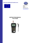
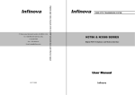
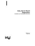
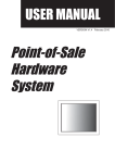
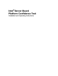
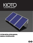
ATMBUS
User's Manual
© - 2015 – AUTOMATROM SRL
(www.automatrom.ro)
All rights reserved
Table of Contents
1. ATMBUS general Information.................................................................................3
1.1. What is ATMBUS?...........................................................................................3
1.2. Hardware structure..........................................................................................3
1.3. ATMBUS communication.................................................................................4
1.4. ATMBUS CRC calculation example................................................................4
1.5. Possible architectures for ATMBUS................................................................5
2. RS232 TO ATMBUS module..................................................................................6
2.1. General information.........................................................................................6
3. ATMBUS MDB MASTER module...........................................................................7
3.1. General information.........................................................................................7
3.2. Connecting ATMBUS MDB MASTER module.................................................8
3.3. Message headers............................................................................................9
1. ATMBUS general Information
1.1. What is ATMBUS?
ATMBUS interface were developed for quick an easy vending development.
ATMBUS makes the vending development very fast and easy, both on hardware
and software levels. This architecture, is, mainly, created from many diferent
hardware modules that can be used to control payment systems, I/O devices, LCD
displays and more, over a single serial port, using a master module or even a PC or
SBC (Raspberry PI, Banana PI, etc.).
The bus can be connected to a PC or SBC using a single RS232 port, each module
recognizing only the messages that are addressed.
Any project can be easily developed, starting with a simple vending dispenser and
up to very complex vending machines, using Android tablets, Raspberry/Banana PI,
touch-screens, printers, bar-code scanners, etc.
1.2. Hardware structure
Physically, ATMBUS is connected using a 2x5 pin connector, with standard 2.54mm
pitch. See Fig.1 and Table 1 for details.
Fig. 1
Pin
Function
Pin
Function
1
Bus DATA
6
N/C
2
N/C
7
N/C
3
N/C
8
N/C
4
GND
9
5Vcc
5
GND
10
N/C
Table 1 – Pinout for ATMBUS connector
Pin no.1 is used also for sending and receiving messages over the bus. Using this
architecture, any of the available modules can act as a master for the entire bus.
This can simplify the developing of any vending machine.
1.3. ATMBUS communication
The ATMBUS communication is using the parameters in Table 2
Parameter
Value
Baud rate
9600
Data bits
8
Parity
None
Stop bits
1
Table 2 – ATMBUS communication parameters
ATMBUS communication protocol is very simple and effective, easy to develop on
microcontrollers, PC or SBC boards. One RS232 port (or USB to RS232 converter)
is user. All other ports on your equipment can be use for other purposes, so you will
no longer need complex wiring or external devices such as USB hub, USB hub
power supply, etc.
The communication protocol is universal, consisting of 5 header bytes, message
body and a simple XOR CRC.
Header <5 bytes>
Content <variable length>
CRC <1 byte>
Table 3 – ATMBUS message package
Because it is a one wire communication, using same wire for both RX and TX, the
messages sent to the ATMBUS will be received as an echo on the serial port. This
could be an advantage controlling the communication (verifying the sent messages,
or simply sniffing the communication for an easier debugging).
For example, if the master (PC or SBC) is sending the message
“MDBSW<0x30><0x30><0x4F>” to ATMBUS, this message will be instantly echoed
back to the master. The message received from the ATMBUS module addressed
will immediately follow the echo message (for example “MDBRW<0x00><0x4F>”
meaning ACK from an MDB bill validator which received RESET command).
1.4. ATMBUS CRC calculation example
For this example we will use a RESET message, send to an MDB validator
connected to an ATMBUS MDB MASTER module.
Header
Message body
CRC
ASCII+HEX
“MDBSW”
<0x30>
<0x7F>
HEX only
<0x4D><0x44><0x42><0x53><0x57>
<0x30>
<0x7F>
Table 4 - ATMBUS CRC calculation example
<0x4D> xor <0x44> xor <0x42> xor <0x53> xor <0x57> xor <0x30> = <0x7F>
If the message CRC is correct, the addressed module (in our example the MDB
MASTER module) will receive the command, send it to the MDB peripheral, receive
the response from the MDB peripheral and answering to the ATMBUS.
If the CRC value is incorrect, then there will be no answer on the ATMBUS.
Each module type has a dedicated header for received messages and for
transmitted messages. For details about header, please see the section for the
module you need.
1.5. Possible architectures for ATMBUS
ATMBUS modules and peripherals can be used in two big architectures:
a. Using one ATMBUS module as a master;
b. Using a PC or SBC (Raspberry PI, Banana PI, etc.) as a master. For this
architecture you must use one ATMBUS TO RS232 interface converter (see
description on Section 2).
ATMBUS modules
2. RS232 TO ATMBUS module
2.1. General information
This device is needed whenever you need to connect any ATMBUS module to an
RS232 device (PC, SBC, PLC, etc.). The device is powered from the ATMBUS (you
need at least self powered ATMBUS module or you need at least one external
powered ATMBUS module).
It is equipped with a female DB9
connecotr to connect to an
RS232 port and with a 2x5pin
(2.54mm pitch) to connect to an
ATMBUS.
It is necessary only one RS232
TO ATMBUS module to connect
many ATMBUS interfaces.
3. ATMBUS MDB MASTER module
3.1. General information
This device can be used to
send, in a very simple
manner, any command to an
MDB bus, without any CRC,
timing or 9th bit complication
and receiving the response
from any MDB peripheral
directly to the host, after
Fig. 2 – Modul ATMBUS MDB MASTER
CRC verification.
It can be used widely to connect any MDB device (coin acceptor, bill validator,
cashless device, etc.) to any RS232 host (PC, Raspberry Pi, Banana PI, PLC) or,
using an USB to RS232 converter, to any USB host.
This device can also act as an ATMBUS master, because it is equipped with a PIC
Microchip 18F26K22 microcontroller.
First function of this device is to convert ATMBUS signals to MDB signal. Beside
that, it also provides the following low level functions:
- Automatic CRC calculation for sent MDB messages. The user application does not
need to calculate the CRC for sent messages. This function is included in the
board's software.
- Automatic CRC calculation for received MDB messages. The board automatically
extracts and verify the CRC on the messages received from MDB peripherals. Then
it returns to the host the received message without MDB CRC.
- Automatic ACK/NACK for MDB peripherals. The board will automatically ACK or
NACK to the peripheral, based on CRC in the critical time of 5ms which is
considered NACK for the MDB devices.
- Automatic 9th bit manipulation. The board will set or unset the mode bit for MDB
peripheral, according to the message received from the host. The user's application
does not need to handle this bit. The communication between the host and the
board is based on standard 8 data bit communication.
3.2. Connecting ATMBUS MDB MASTER module
The board is connected to the system using J5 (MDB master connector), EXPBUS
(ATMBUS connector), J2 (MDB payment systems power connector), J1 (5VCC
power only mini USB connector, with no USB communication).
Fig. 4 – Board connectors
Pin
Mode
Function
1
OUT
12/24VCC – alimentare sisteme de plata MDB
2
GND
GND
3
GND
GND semnal MDB
4
OUT
MDB TX – transmisie spre bus-ul MDB
5
IN
6
OUT
MDB RX – receive from MDB bus
MDB sleep mode (not used in this application)
Table 5 – J5 (MDB connector)
Pin
Function
Pin
Function
1
Bus DATA
6
N/C
2
N/C
7
N/C
3
N/C
8
N/C
4
GND
9
5Vc
5
GND
10
N/C
Table 6 - EXPBUS
Pin
Type
(+)
IN
GND
Function
Payment systems power supply (12Vcc or 24Vcc,
according to your payment systems need
GND Payment systems GND for power supply
Table 7 – J2 – Payment systems power
Pin
Type
Function
1
IN
Board power (5Vcc) if the board is connected to a not
powered ATMBUS (connect a 5Vcc power supply to
this connector only if the bus is not powered withit
other module).
2
N/C
Not used
3
N/C
Not used
4
N/C
Not used
5
GND GND
Table 8 – J1 – 5Vcc power supply
3.3. Message headers
The host should manage the MDB protocol according to NAMA MDB specifications.
There are two headers in the communication with ATMBUS TO MDB module:
All messages sent by the host must start with “MDBSW” header.
All messages received by the host from the module will start with “MDBRW” header.
For example, below you can find a dialog with MDB bill validator. In this example,
“HOST” is the RS232 equipped device (PC, PLC, SBC) or an ATMBUS module with
master capabilities and “MODULE” is the ATMBUS TO MDB module.
HOST - “MDBSW<0x33><0x7F>” → Poll the bill validator to obtain “JUST RESET”
MODULE - “MDBRW<0x06><0x09><0x40>” → “JUST RESET” message received
from the MDB bill validator.