1
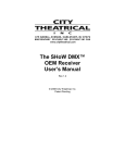
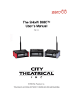
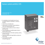
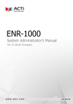
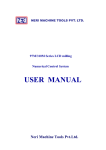
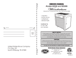
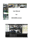
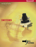
H
D
D
HDD Series MDVR
USER'S MANUAL
V1.09E
Contents
CHAPTER 1:PRODUCT APPLICATION AND PARAMETER--------------------------------------1
CHAPTER 2:PRODUCT INTERFACE DEFINITION AND FUNCTION DESCRIPTION-------4
2.1:MDVR Out-design and Dimension--------------------------------------------------------- 4
2.2:Definition of functional MDVR back panel interface----------------------------------- 5
2.3: Brief instruction of commonly used interface cable ---------------------------------- 6
2.4: USIM card installation------------------------------------------------------------------------ 7
2.5: Instructions of function keys on remote controller ----------------------------------- 7
CHAPTER 3:SYSTEM MENU SETTING INSTRUCTIONS ---------------------------------------- 9
3.1:Demo working and user login--------------------------------------------------------------- 9
3.2:System menu construction chart----------------------------------------------------------- 10
3.3:System setup------------------------------------------------------------------------------------ 10
3.3-1:Basic-------------------------------------------------------------------------------------------10
3.3-2:Power off/on setup------------------------------------------------------------------------- 11
3.3-3:Network setup------------------------------------------------------------------------------- 11
3.3-4:Password setup------------------------------------------------------------------------------11
3.4: Recording setup--------------------------------------------------------------------------------12
3.4-1 :Normal setup--------------------------------------------------------------------------------12
3.4-2 :Channel setup-------------------------------------------------------------------------------13
3.4-3 :Timing setup-------------------------------------------------------------------------------- 13
3.4-4 :Sub-stream setup------------------------------------------------------------------------- 13
3.5 :Vehicle information--------------------------------------------------------------------------- 14
3.5-1 :Sensor setup-(alarm input)-------------------------------------------------------------- 14
3.5-2 :G-Sensor setup-----------------------------------------------------------------------------14
3.5-3 :Speed setup--------------------------------------------------------------------------------- 15
3.6: TOOLS-------------------------------------------------------------------------------------------- 15
3.6-1:Format disk management---------------------------------------------------------------- 15
3.6-2:Configure manage and log search----------------------------------------------------- 16
3.6-3:Motion detection--------------------------------------------------------------------------- 16
3.6-4:System upgrade---------------------------------------------------------------------------- 17
3.7 MODULE MANAGE----------------------------------------------------------------------------- 18
3.7-1:3G setup-------------------------------------------------------------------------------------- 18
3.7-2:WIFI setup------------------------------------------------------------------------------------ 19
3.7-3:PTZ set up------------------------------------------------------------------------------------ 19
3.8 :System information--------------------------------------------------------------------------- 20
3.9 :Recording playback---------------------------------------------------------------------------20
CHAPTER 4: COMMON SHORTCUT SETUP------------------------------------------------------ 22
4.1 :Cables testing and power on----------------------------------------------------------------22
4.2 :Recording setup------------------------------------------------------------------------------- 22
4.3 :PTZ connection and setup------------------------------------------------------------------- 24
4.4 :Playback recorded files on PC--------------------------------------------------------------25
4.5 :Vehicle fast connecting to CMS------------------------------------------------------------ 26
APPENDIX1 : CMS PLATFORM INTERFACE------------------------------------------------------ 27
APPENDIX2 : FAQ--------------------------------------------------------------------------------------- 28
APPENDIX3 : CORRESPONDING TABLE OF STORAGE SPACE------------------------------ 30
HDD Mobile DVR User Manual
1
CHAPTER 1: PRODUCT APPLICATIONS AND PARAMETERS
1.1 MDVR is a cost-effective, function extensibile equipment which is designed for on-board video
monitoring and remote monitoring, It uses the rapid handling device and embedded Linux platform,
combined with the most advanced H.264 video compression / decompression technology , network
technology and GPS technology . Take the HDD as the main memory, and SD card as auxiliary storage
MDVR can realize many functions such as audio-video recording , vehicle's driving information
recording , remote management and GPS signal upload . With central control software, it can realize
the central control of alarm linkage , remote management and playback analysis .With simple and
modern appearances, MDVR is vibration-proof , installation-friendly, has powerful functions and stable
performances, etc.
FORM 1 : MDVR PRODUCT'S SPECIFICATION PARAMETERS
Items
Parameters
Language
OSD
Password
Video input
Video output
Preview
Recording Ratio
Image Compression
Audio input
Audio output
Recording mode
Video format
Video stream
Specifications
Chinese/English
System
Graphical User interface OSD menu
Users Password/ Administrator Password
4CH VIDEO INPUT 1.0Vp-p 75
1CH VIDEO OUTPUT 1.0Vp-p 75
Video
1 CH/ 4 CH Preview.
PAL 25 Frame/s NTSC 30 Frame/s
H.264 Main profile 100fps/s
4-CH
Audio
2-CH
Audio & Video sync.
D1/HD1/CIF
ISO14496-10
D1: 2048Kbps ~ 400Kbps
Image
processing & Video Rate kbps HD1: 2048Kbps ~ 380Kbps CIF: 1536Kbps ~ 128Kbps
8 levels optional. Highest:1 level
storage
8KB/s
Audio Bitrate
Support a 2.5-inch 1TB SATA HDD, support a SD card
Storage
maximum 32GB for each.
6 alarm input,
Alarm input
Alarm
2 alarm output, high level 12V output
Alarm output
Support 2-RS485 interface
Rs485 Interface
Communication RS232 Interface
Support 1-RS232 interface
Port
802.11b/g
WIFI Interface
Connect to station reporter or control panel
Extended control panel
interface Audio power amplifie r Support 2-ch audio power amplifier output
WILESS 3G(HSDPA/WCDMA) Optional 3G(HSPA/WCDMA))module
Built-in GPS module, Geographic co-ordinates, speed can be read in coding
GPS
flow, and can be wireless uploaded. optional
G-SENSOR Built-in G-Sensor
PC playback
Video playback on Pc and analyse the vehicle info in the file
Software CMS
Video preview via WIFI GPS upload alarm upload,
central command and parameters configuration, etc.
Upgrade Support SDcards/USB/HDD upgrade.
1
HDD Mobile DVR User Manual
2
FORM 2 : MDVR BASIC ELECTRICAL PARAMETERS LIST
Parameters
Items
Power input
DC8-36V
Power output
Impedance
12V
4V
5V
75
Video output Volt
2Vp-p
Vehicle key signal
I/O interface
Operating Temp
-40 -80
Specifications
8V
36V, When long-term under 8V, or long-term over 36V,
auto power off, and enter protection mode.
12V +/-0.2V
Max:2A.
OFF
On
75Ù for each video input impedance
Input 2Vp-p CVBS analog signal, reveal device input need 75Ù
impedance to fit
<4V Low level alarm
4VHigh level alarm
Under well-ventilated enviroment.
1.2 MDVR PRODUCT APPLICATION CONNECTION SCHEMATIC DIAGRAM
Figure 1-1, MDVR can be used both in common and special vehicles video monitoring or remote
monitoring such as bus , logistics car , freight car , long-distance travel bus , taxi , tanker, school bus ,
police car , patrol car etc . Front end acquires signal by on-board special camera , through special video
line transfer it to MDVR mainframe to process video compression , local store in HDD. Model with
3G module can realize remote monitoring, recording, upload etc. Model with GPS function can realize
real time vehicle positioning; Schematic diagram is a common application mode, the actual use of
various functions will be changed as the existence of the modules change.
Figure 1-1
Access Stream File
Autodown Database Gateway media storage GIS
file server server
server server server server
Client
Control Panel Monitor Speaker Alarm
2
Client
HDD Mobile DVR User Manual
3
1.3: MDVR NOTICE:
To make sure MDVR safety use, acquire satisfactory performance, and extend the service life
of the equipments , please fully consider the following factors when install the equipment :
1.When install and operate the equipment , please obey all the electronic products guide, vehicles'
and other connection equipments requirements
2.Power supply and equipment grounded : Direct input range of the machine power supply is from
DC 8V-36V , please don't get inverse,and.input can t be short circuit.Please note the power supply
capacity of the power line. Even the equipment is shut down , it may be charged . please avoid short
circuit . Before connect with other external devices, please cut the connection between this
equipment and the power supply. The input mode of equipment sensor is level mode , with external
voltage below 4V is considered as low level , above 4V and below 30V is considered as high level.
Beyond 30V will damage the equipment. Correctly connect the earth wires of the device and the
vehicle and form a loop;
3.Humidity requirements : Install equipment in dry environment, avoid damp, water-drop, water
spray and other places. Don't take the equipment installed in places where water will sag or wet
places liquid will drip down ; Do not use wet hand to touch the equipment,Do not stand in the water
or touch with other water places while contact the equipment, it may get electric shock
4.Installation position:
To extend the life of the equipment, please try to install it in place with weak vibration, such as
behind the driver's seat .The equipment should be installed on the vehicle's ventilation installation
part .Equipment installed on the plane should remain a distance of 6 inches (15 centimeters)
away from other objects to assure the air flow and heat dissipation ; Don't install it on the enclosed
area, such as car trunk. This machine can be right side installed or side loading. The equipment's
external wiring must have the enough intervals and external flame retardant protection , to ensure
the wire not to be bent or leakage of electricity due to wear and vibration; Ensure that equipment
away from heat source of the vehicle, the equipment can't have sundry pile up around, prohibit
placing anything on the equipment .
5.Equipment safety:
Ensure passengers or the driver can't intervene and damage the equipment unit, camera, wire and
other accessories . Don't install the equipment near other components of vehicle ; When install
equipment components, camera, accessories and wire, launch vehicles may cause damage to the
equipment, Keep the vehicles static during the installation process ,to prevent equipment falling
from vehicles.
Installation notes:
1.Equipment contains the electronic devices, please handle gently during transport .
2.All installation and maintenance must be executed by the professional qualified person.
3.This product can't be installed in part of the vehicle where there was erosion by rain or other
liquid for a long time .
4.Without professional guide, please do not open or unload the equipment.
5.Keep fuselage away from the heat source, dust and strong magnetic fields.
6.Do not put heavy objects on the equipments.
7.Don't change any modules when the mainframe is charged.
8.The equipment output power shall not connect to devices that are not recommended.
3
HDD Mobile DVR User Manual
4
CHAPTER 2 : INTERFACE AND DESCRIPTION OF THE FUNCTIONS
Unit
2.1 MDVR OUT-DESIGN AND DIMENSION
Front panel
mm
SIM Card Installation
IR
A-OUT V-OUT
USB2.0
RJ45
Lateral plate
Back
Back panel
Figure 2-1 MDVR structure size schemes
Figure 2-4 Indicator diagram
Figure 2-2 MDVR appearance schemes
LOCK
A-OUT V-OUT
Video out
Hard disk box
Audio out Work LED
IR
USB2.0
RJ45
Panel Indicator Light Description
Audio OUT
Video OUT
Light will be on when recording
Light will be on when the power
supply can work normally
:Light will be on when the HDD exist
Light will be on when the SD card
exists.
Light will be on when the U-disk
installation
Light will be on when theGPS
module exists
Light will be on when 3G module
exists
Light will be on when the WIFI is
exists and ON.
Hard disk heating indicator
USB2.0
IR
RJ45
Figure 2-3 MDVR front panel schemes
4
video input 1/2/3/4. Have each input
signal indicator, otherwise the lamp.
Infrared sensor receiving remote
control signal
HDD Mobile DVR User Manual
5
2.2: DEFINITION OF MDVR BACK PANEL INTERFACE
SPEAKER
POWER IN
3G Antenna
WIFI Antenna
GPS Antenna
RS485 RS232
SENSORS SPEED
CAM1 CAM2 CAM4 CAM4
AUDIO/VIDEO
OUTPUT
EXTENSION OUTPUT
CONTROL PANEL
Figure2-5 Definition of MDVR back panel interface
FORM 3 Explain of MDVR back panel interface
Interface
Discribtion
Name
WIFI Antenna Interface
Wireless Local area network antenna interface
WIFI
GPS antenna interface
GPS antenna interface
GPS
2 G / 3 G antenna interface
2 G / 3 G antenna interface
2G/3G
The power input interface
The power input interface
DC8-36V
Print interface
System information adjustment interface
MCU/ICP
Extension interface
EXTENTION Control panel interface
VIDEO output interface
VIDEO- OUT Video output
AUDIO- OUT Audio output
Audio output interface
CAN-BUS Bus electronic control network
Bus interface
SENSORS Switch input interface, high level (> 4 V) is effective
Sensor interface
Bus Speed pulse input interface , input bus Speed
SPEED
Bus Speed pulse
pulse signal differential input
input interface
RS485/RS232 interface RS485/RS232 RS232&RS485 serial data communication interface
SPEAKER Audio power amplifier output
Speaker interface
5
HDD Mobile DVR User Manual
6
2.3:BRIEF INSTRUCTION OF COMMONLY USED INTERFACE CABLE
Power cable:
As the following map shows, one end is a white plug with 6 pin, connect to the white of the equipment's
back pannel. Red and black cable to connect to the car's battery directly. The red cable is connected to
the positive electrode, the black cable is connected with the negative pole .The yellow cable is
connected to the ignition line. Mainframe equipment opens automatically after opening the car with the
car key. Autodelay closes after closing the car . The yellow cable connects to the gear where the
car key open all the dashboard light. ( the gear before start the motor ).
RS485 RS232
SENSORS SPEED
Aviation head
A/V test cable
Power cable
Alarm cable
Aviation head A/V
extended cable
4PIN-AV output
Figure 2-6 Functional MDVR interface roughly matched wiring
Audio/video cable
MDVR approximately has above kinds of accessories,the aviation head A/V test cable is just used
during the test,please do not use it on the installation.When installed,recommend to use the aviation
head AV extended cable. MDVR need to use the 4pin-AV output cable when connect to the A/V
output . or use the AV interface in the front panel. External interface of MDVR can choose from
WIFI/3G/GPS, so the relative module antenna is needed . As figure 2-6 and figure 2-7 .
SPEAKER
EXTENSION
3G antenna
WIFI antenna
GPS antenna
Figure 2-7 MDVR uses correspongding cables according to functions
1.Ensure the battery voltage is between 8V-36V before connection. Otherwise, it
will burn out the equipments .
2.After the cable is connected . please note the insulation between the power line .
Prevent burn out the battery because of the short circuit .
3.The yellow cable must be installed on the ignition line , or the equipment will not
support the delay shut down , and the last video recording will be missed .
4.The installation of MDVR must get positive electrode directly from the battery.
Please don't use iron wire as the ground line . or it will produce negative pulse and
jamming the normal operation of the mainframe . The diameter of power supply
that the positive electrode and negative pole must above 1.5 mm.
Alarm input and output
This equipment has six alarm input interface and two alarm output interface .Alarm input detection
are all level detection. It can connect to various vehicles'driving status such as brakes,turns, door
switches , buttons of emergent alarm . When press the brake vane, MDVR can detect the high level,
or detect the low level. As figure 2-8.
+12V
Braking light
Braking vane
MDVR SENSOR
Figure 2-8
6
HDD Mobile DVR User Manual
7
Alarm output are all level output , The drive ability is 200 MA, if you want larger power devices,
you must connect it to external relays. This is the optoelectronic alarm wiring diagram of Alarm output
As figure 2-9.
MDVR alarm output
+24V
Figure 2-9
2.4: USIM CARD INSTALLATION
For functional MDVR card, if support the wireless network communication, it need to install the USIM
card which is suit for WCDMA/EVDO. USIM card is on the communication board of the mainframe , use
a screwdriver to take down the flap cover from the bottom of the mainframe. Then you can see the USIM
card interface, press it to USIM interface. Please notice the right side and the opposite side. Use
thescrew fix the flap cover after installation.
1
33
22
4
Figure 2-10
2.5 INSTRUCTIONS OF FUNCTION KEYS ON REMOTE CONTROLLER
Power on /off(not
used Temporarily)
LOGIN
Number key area
Picture adjustment
PTZ control
Direction key area
Exit / return
Delete/Cancel
System information
Play back operation key area
4 images segmentation
PTZ control key area
Shortcut key / test key
System information
7
HDD Mobile DVR User Manual
8
Power on /power off NOTE: this function is not used temporarily
If the video has set the password, press LOGIN key to input the password. As the system does
not have recovery and reset function, please remember the password.
LOGIN
INFO
Information
Under the surveillance images, it can be used to switch between single and four images
Press the image segmentation key to show the 4 images ;Under the surveillance image .
Figure keys 1, 2, 3, 4 press this key ,it will show switch sequence as follows: CH1-CH2-CH3-CH4.
Exit to the last sub menu .Finally return to the menu setting and the surveillance images ;
RETURN
Suspend key and single step key when playback video material . Press the key once can
PAUSE/STEP
play one step. Then press the play key to return to the normal playing speed
GOTO
FRAME
PLAY
Playing back , It can jump to point time to start playing
Forward
The forward button when playback video material . There are four gears:2X,4X,8X,16X.
2X 4X 8X,16X
Stop manual video button
Launch manual video button
In Playing process turn down to the next page/next file;
In Playing process turn up to the last page/last file;
PREV
Automatic, preset, adjustment, variable times +, variable times- ,focus +, focus-,aperture +,
aperture- PTZ PRESET RECALL BRUSH
PTZ
F2
Button to play
The rewind button when playback video material . There are four gears
REW
Stop REC
Recording
NEXT
F1
Press this key to frame
F3
F1 is shortcut key , F2, F3 is spare key
NEXT
SYSTEM MENU
8
HDD Mobile DVR User Manual
9
CHAPTER 3 SYSTEM MENU SETTING INSTRUCTIONS
3.1: DEMO WORKING AND USERLOGIN.
Trun on the device after power supply and otherconnecting successfully and according to
installation guidance. Interface refer to Figure 3-1and there are four-image monitoring interface
after the device start working.Press" LOGIN " button on the remote control ,then direct into login
interface,as Figure 3-3 for reference
Figure 3-1
Figure 3-2
INSTRUCTIONS:
DEVICE NUM: User set number for every different device and it will show in the right of the number
input box. User enter the number as showing, one number only for one device .
USER NAME: Including admin and normal user, regular user permission only could enter into video
searching ,playback , information and other menu, but can not set the menu and data. Admin gets the
permission to modify the system parameters.
PASSWORD: Enter password according to the selected user name. When password is correct , select
down button move to " LOGIN " , and press " ENTER " to log in., When password is incorrect, press
" CANCEL " and delete ,then reenter the correct password. Admin password is 111111 , the main
interface after entering password is as showing as f igure 3-4.
Figure 3-3
Figure 3-4
System menu includes seven main menus: SYSTEM, RECORD, VEHICLE, TOOL , PLAYBACK ,
MODULE , INFO. Main menus is as Figure 3-4 shows:
1 All submenu settings must save ,then effect, otherwise invalid.
2. Check box if filled means function selected , not filled means function not selected.
3 Number inputs can use number button on the remote control enter directly or
use soft keyboard. Letter only can complete via soft keyboard,press " RETURN "
button to get back .
9
HDD Mobile DVR User Manual
10
3.2
SYSTEM MENUS CONSTRUCTION CHART
SYSTEM
BASIC
POWER
NETWORK
PASSWORD
RECORD
NORMAL
CHANNEL
TIME LIST
VEHICLE
SENSOR
SPEED
G-SENSOR
TOOLS
CINFIGURE
PLAYBACK
DETECTION
SUB-STREAM
LOGIN
FORMAT
Figure 3-5
INFO
MODULE
3.3
LOG
WIRELESS
WIFI
PTZ
SYSTEM SETUP
Figure 3-6
Figure 3-7
It is the first menu in the main menu and it includes"BASIC SETUP ;POWER SETUP ;NETWORK
SETUP and PASSWORD SETUP".
3.3-1 BASIC SETUP
Basic setting: It is used for device system time and some basic function setting .
1.DATE FORMAT: Press"ENTER"to type Y-M-D/ D-M-N.
2.DATE and TIME Setup: Press"ENTER",and then press"- " or"+"to set the data,press enter to confirm .
3.During operation timeout (can set from 30-3600 seconds) and device number modification, press
"CANCEL"to delete, and then press the number button .
10
HDD Mobile DVR User Manual
11
YMD
06:00:00
5
MIN
06:00:00
22:00:00
30 (30~3600s)
Figure 3-8
3-1440min
Figure 3-9
4."COMPANY NAME","VEHICLE NUM","DRIVER NAME""LINE NUM"Setting: Press "Enter" key
to pop up keyboard window, then use left/right/up/down/enter key to setup.
5. When turn on automatic adjustment function, in the default time , the system will adjust the time
via GPS automatically when it comes to the time for adjustment.
6.HOME PAGE : There are "DEV STA"and "QUAD" two options, QUAD is the normal monitoring
screen when we turn on the device. If select DEV STA system information will appear in the four
channels normal screens .It is equal the function when we press the button"INFO".
3.3-2 POWER OFF/ON SETUP
1.Power on/off mode : Select from " TIME /ACC" mode, and press " ENTER " to switch.
ACC mode means when the vehicle powers on, the device will start working. Recommend to select it
as the default mode. Timing mode means the device will turn on or power off during the fixed time.
2.Delaying off setting :when select ACC mode or TIME mode,can set delay off and the time is
3-1440mins, after setting ,demo will continue the delaying time.
3.3-3:NETWORK SETUP
PASSWORD SETUP
NETWORK SETUP
CENTER SETUP
SERVER IP:
CONTROL PORT
PSW ENABLE
USER PSW
CONFIRM PSW
ADMIN PSW
CONFIRM PSW
LOCAL SETUP
IP ADDR:
NETMASK:
GATEWAY:
SAVE
SAVE
Figure 3-10
Figure 3-11
1.CENTER SETUP :
The server IP is the same as the CMS server IP. Control Port is the same with Gateway Server Port
Number "8501".
2.Server IP is the IP that MDVR uses to connect to the CMS platform via 3G /WIFI/RJ45. Normally it
is the fixed WAN IP. Our devices can support 3G / WIFI/RJ45 functions. If the devices do not have
these functions,this menu can be passed.
3:Local IP Settings: general according to local area network to set, set up a local LAN IP address and
then set the netmask and gateway, set up, with the cable network router and Rj45 interface connected,
and keeps it from LAN connected to the wan,then connect to CMS platform,Flow chart as figure 4-10.
3.3-4 PASSWORD SETUP
1:Press"ENTER"to switch ON/OFF.
2:Admin can modify the user password and admin password. The default password for admin
password is "111111", after password modification completed, exit the menu and use the new password
to enter the interface.
11
HDD Mobile DVR User Manual
12
3.4 RECORD SETUP
Figure 3-13
Figure 3-12
It includes: Normal setting, Channel setting, timing setting and sub-stream setting. It can reach
the highest quality recording after settings. With default settings, the device will start recording after
powering on. But in order to reach better recording function, you can modify the related parameters.
Record menu is shown as figure 3-13.
3.4-1
NORMAL SETUP
AUTO
TIMED
ALARM
15mins
30mins
45mins
60mins
NORMAL SETUP
SYSTEM: NTSC
REC MODE:
PACKET TIME:
OVERWRITTEN:
VOLUME OUT: 15
ALM PRE-REC TIME(s)
ALM REC DELAY(s):
ALM OUTPUT TIME(s)
REC PROTECT TIME:
REC VEHICLE INFO:
0-60S
30-900S
15
5-240S
3days 1-15days
30
30
ON
Figure 3-14
During settings modification, select menu to become green , then press "E nter " to switch. Press
"C ancel " and before input numbers.
1.TV SYSTEM: Press "Enter" to select PAL/NTSC system.
2.REC MODE: Press "Enter" to select AUTO/ ALARM/TIMED mode
3.PACKET TIME: It is the time range when the recording video will be packed into one file. Select
from 15/30/45/60 mins, and 15 and 30mins are the better options .
4.Automatic recording overwrite can be selected on /off, if the SD card is full, the following recording
video will overwrite the first recording videos automatically.
5.ALARM PRE-REC TIME(S): When the alarm occurs, it will pre-record a period of time and pack to
the Alarm recording. ( 0-60s range)
6.ALARM REC DELAY(S): After the alarm stops, it will keep recording a period of time and
pack into the alarm recording(30-900s).
7.ALARM OUTPUT TIME(S): It means the alarm output time range when alarm occurs and
connects to the output device.( 5-240s )
8.REC PROTECH TIME: It means the time that recordings are stored in the SD cards, during the
protection time, even if the SD card is full with alarm recordings, it will not be overwrited, press
"Enter" to select from 1/3/5/7/10/15 days.
9.REC VEHICLE INFO: Select ON/OFF. When enables this function, recordings will contain all the
alarm info, GPS info and other information which can be viewed via playback software.
10. VOLUME OUT: volume of the playback,1-15 Optional.
12
HDD Mobile DVR User Manual
13
3.4-2 CHANNEL SETUP
CH ENABLE RES. FPS QUAL MIC PREVIEW VOLUME
CH1
ON
D1
25
3
ON
ON
15
CH2
ON
D1
25
3
ON
ON
15
CH3
ON
CIF
25
3
ON
ON
10
CH4
ON
CIF
25
3
ON
ON
10
1.Set some properties of each channel,such as RES,
QUAl MIC AUDIO,VOLUME etc .
FR: 1-25 optional,when reach 25 FR it is real-time
recording. 1-8 grade QUA optional, 3 grades is
defaulted and 1 is the best, 8 is the lowest. If
some channels do not need video or audio recording,
turn it off to save the HDD storage .
MIC: Must be set "ON" in order to record and
monitor audio.VOLUME adjustable1-15.
QUA
RES.
Figure 3-15
CHANNEL SETUP
HIGH
LOW
3.4-3 TIME LIST SETUP
00:00--23:59
00:00--00:00
00:00--00:00
00:00--00:00
00:00--00:00
00:00--00:00
00:00--00:00
00:00--00:00
00:00--00:00
00:00--00:00
00:00--00:00
00:00--00:00
00:00--00:00
00:00--00:00
00:00--00:00
00:00--00:00
Figure 3-16
INSTRUCTIONS:
1.See Figure 3-14 in REC MODE select
"TIME LIST " mode,then set the time for recording.
Move option to the time needs. Press plus or minus
key ( number 8 or 9 ) and move to the numbers that
need setup. Setup each time according to the
number key.
Time list
Cursor move to the
time, then press plus
and minus key to
operate
3.4-4 SUB-STREAM SETUP
SUB-STREAM
Figure 3-17
1.SUB-STREAM SETUP: Parameter settings during
the video transmission to the internet via 3G/wifi/rj45
will affect whether it is clear or not when we see the
video on CMS. Also, the transmitting speed mainly
depends on the local network speed. Video RES can
set to CIF or QCIF .
2.FRAME RATE SETUP: Appropriate frame rate
changes with the bit rate changings, one one
relationship. The default bit rate is 96 and frame rate
10. Users should setup according to their network
situation.If network bandwidth is good enough, they
can set bits rate at 384 and frame at 25, or set in auto
mode.
BITS RATE:
Auto
SUB-STREAM FRAME RATE:
13
HDD Mobile DVR User Manual
14
3.5 VEHICLE INFORMATION
Figure 3-18
Figure 3-19
It includes SENSOR, SPEED, G-SENSOR SETUP.
SENSOR SETUP
Figure 3-20
3.5-1 SENSOR SETUP- ALARM INPUT
1.When users install MDVRs, define the sensors according to different port settings, see the
figures 3-20. Like change name "INPUT" to "Front door", "Brakes", and etc.
2."ENABLE" on means switching on the sensor, user can select alarm mode as the recording mode,
and then select record and alarm on/off on this menu. Actually, sensor input is also alarm input, with
high/low level effective. Users normally use above 5V high level to form the loop.
G-SENSOR SETUP
3.5-2 G-SENSOR SETUP
Figure 3-21
Before setup acceleration, users must clear X/Y/Z parameters. Acceleration can be analysed as
a three-dimensional X/Y/Z coordinate axis, which can express three status: up-down ,right-left ,
front-back. Uniform speed will not affect on it. Acceleration setup mainly setup thresholds that are
defined via testing. Please see Chapter 4.3 for more detailed information.
14
HDD Mobile DVR User Manual
15
3.5-3 SPEED SETUP
SPEED SETUP
GPS
VEHICLE
SPD SOURCE GPS
COEFFICIENT 0
KM
SPD UNIT
NAME
KM
MPH
ENABLE THRESHOLD RECORD
LOW SPD
OFF
060
OFF
HIGH
OFF
120
OFF
SAVE
Figure 3-22
1.When setting GPS /VECHILE to get the speed , please press " ENTER " to switch , if select GPS,
so should require demo have GPS module and with signal, that can pass the speed to vehicle and the
vehicle can get the speed from GPS.
2.If select" Vehicle" to get the speed ,need to take the pulse sensor to calculate the speed ratio,
( coefficient =pulse /speed ) , pulse sensor connects to demo ports two line : SPEED-A and SPEED-B.
this speed ratios requires during vehicle working in accordance with the seted speed and received
pulse .
3.Unit of speed is switchable,high-speed alarm setting is turn valid. Threshold means limit the vehicle
speed. Speed units is as the same as above .if video is turn on ,when is overspeed, demo will occurs\
alarming ,besides ,also need to set the recording mode as alarm recording in" record setup" -- " Normal
setup " .
3.6
TOOLS Manage tool including 4 menus: FORMAT ,CONFIGURE, LOG AND DETECTION.
Figure 3-24
Figure 3-23
3.6-1 FORMAT DISK MANAGEMENT
SELECT CARD HDD
FORMAT
WARNING If you format the sd card/hdd,
all of the data will be lost!
Figure 3-26
Figure 3-25
Refer figure 2-2 or 2-5, Before turn on device should insert HDD, please format the HDD and
the set then video under normal circumstances. please refer above pictures for the Format
procedures . Press"Enter"and select HDD/SD1, then format , according to prompts to select
whether format or not .
NOTE : All the storage database be deleted when runs format ,please confirm whether
there is storage file or other important files information.
15
HDD Mobile DVR User Manual
16
3.6-2
CONFIGURE MANAGE AND LOG SEARCH
START TIME 2012-03-01 00:00:00
END TIME 2012-03-01 23:59:59
DATE
12/03/01
12/03/01
12/03/01
12/03/01
TIME
14:45:07
14:46:55
14:55:38
14:56:25
ALL
EVENT NAME
POWER ON
VIDEO LOST1
FILE PLAYBACK
REC NORMAL SET
Figure 3-28
Figure 3-27
Configure manage mainly including import and outport system current
configuration and restore factory configuration.If operates outporting current
configuration,system will store the information into HDD and if others MDVRS
configuration are the same as this models' , so we can insert the HDD into
others MDVRS ,then operate input current configuration. Restore factory
CONFIGURE
configuration: IF can not find out the reasons when problems get during system
MANAGE
setting or the demo running out of problem. We can restore factory configuration
and then reset the demo.
Select starting and ending time and issues type( ALL/ALARM /USER), the start
to research , the system will record such related information: system turn on,
user setting ,networking setting ,video lost ,playback file , motion detection
LOG SEARCH alarm,system setting etc.
3.6-3
MOTION DETECTION
Motion
Detection
Figure 3-29
Select " MOTION DETECTION " in manage tool module and enter into motion detection setting.
In user selected area ,when there are moving objects, Information will be written in the log file which
named MD ALARM events after the system detected. If its continuous alarm or several alarms in 30S,
then the system write the log every 30S.Users can view the information under manage tool-Log query.
If user set the Alarm recording as the recording mode, when occurs motion detection. the video during
this period will be packet alarm recording . User can view and playback this video via searching alarm
recording query.
Step1. Enter main menu, Select recording setting -manage setting-set alarm recording as
the recording way.
Step2. Set per-recording and delayed time, In order to confirm the alarm events continuity,
2mins will be better .
Step3. Enter main men-manage tool-motion detection-enable function turns ,set detection
sensitivity and detection area ,then save
16
HDD Mobile DVR User Manual
17
PROCEDURES OF SETTING DETECTION AREAS:
Figure 3-30
Select"Configure"and press "ENTER", enter into motion detection configurationinterface.
(Figure 3-30).
Step1 : Select the first Box , press"Enter"gets yellow , after move the arrow keys ,gets dark green )
Step2 : The select second box, the diagonals of the rectangle between these two boxes is the
selected area, ( after selected"ENTER"the diagonal region gets into a dark green .)
Step3 :, press"Return"to last interface and then save. Sensitivity divided into Low ,medium and
high grade, under high-sensitivity mode, it is capable of sensing changes in light and under low
sensitivity status , only can detecting the moving objects .
" Enter " and "C ancel " can delete the selected areas , all the parameters set must
confirm save after configuration, if is successful modified there will prompted
save success.
3.6-4:SYSTEM UPGRADE
Figure 3-31
The procedures are as bellowing :
Step1: Please copy "dvr-xxxxxxx.crc"upgrade file to U-disk of the root directory.
(But also can use the SD card to upgrade).
Step2: Insert U-disk into USB slot , turn on Demo and then enter into"Upgrading".
Step3: Enter into the system after upgrading successfully ,Press enter Key F1 on the remote
control to view the system version information.
Do not shut power or pull out USB during the device is upgrading , otherwise it will
break the system device.
17
HDD Mobile DVR User Manual
18
3.7
3.7-1
MODULE MANAGE
3G SETUP
INSTRUCTIONS: When device need connect the network , must have setting in this menu .
1)Insert USIM card , which can support two options : WCDMA and EVDO, USIM card slot is in the
communications board , Remove the small plate which under the demo , then can see the USIM slot,
detail installation information please refer to 2.4 section .
2)After installing the USIM card and plug in the 3G antenna , ensure that the system can receive
excellent 3G signal .
Figure 3-32
Figure 3-33
3.Edit the following information in the" WIRELESS ".
1)Wireless dial status" ON ".
2)In communications type , if the demo support WCDMA ,then select WCDMA , Otherwise, if it is
EVDO , then select EVDO , Press the remote control key" ENTER " to switch .( Support WCDMA or
EVDO , it is depends on the model type ,every demo only can support one mode ).
3) APN and Central number of 3G, need to enter APN and central number according to local
network operator offers. Someplace need enter user name and password, then can get the signal
well ,when your demo can not get signal normally ,please confirm whether the 3G setting is correc
t or not .
Figure 3-34
Figure 3-35
4)Press the remote control key INFO can view related 3G communication information, if shows dials
successfully and with excellent signal , then can runs communication via 3G , ( Confirm the IP
address correct , control port , Network setting ,and USIM card data flowwhether enough or not ) .
5)If want connect the demo into CMS server , then enter sever IP address and control port number in
the Picture showing(figure 3-10 ).
18
HDD Mobile DVR User Manual
19
3.7-2
WIFI SETUP
WIFI SETUP
ENCRYPT TYPE:WEP
ENABLE
ENCRYPT
AUTH MODE
ENCRYPT TYPE
SSID
PASSWORD
ON
ON
OPEN
IP ADDR 192.168.001.012
NETMASK 255.255.255.000
GATEWAY 192.168.001.001
WEP
WIFI SETUP
SAVE
Figure 3-36
INSTRUCTIONS:
Insert WIFI antenna into the backside mount of the demo , Edith the following information at the
interface as pictures (Figure 3-36)
1.Make " ENABLE " and " ENCRYPT " status " ON ", authentication mode including WPA ,WPA-PSK,
OPEN and share. authentication mode is not effective currently ,so only choose the " OPEN " state
(Open-certifications is not required).then WIFI can communicate properly ,Select " WEP "
encryption, refer figure 3-36 , Press " ENTER " key to set above information and different options
switching.
2.Enter the SSID and password ( The wireless network name and password ), IP ,MASK and
gateway , all the set must be match with your local wireless LAN , IP address ,netmask and
gateway press" CANCEL " and the number keys to setup .
3.Check system information, refer figure 3-35, if the WIFI signal is over -60db, it indicates WIFI
signal is excellent .
4.If want connect into CMS server ,refer the center of the IP field in figure 3-10, enter the CMS
center IP and port number.
3.7-3
PTZ SETUP
PTZ SETUP
Protocol Baudrate Dbit Sbit Verify Num
PTZ SETUP
CH1 PELCO-D
2400
8
1
None
1
CH2 PELCO-D
9600
8
1
Even
12
Ch3 PELCO-D
9600
8
1
Even
12
CH4 PELCO-D
9600
8
1
Even
12
SAVE
Figure 3-37
INSTRUCTIONS :
1.Protocol:PELCO-D and PELCO-P optional.
2.Baudrate:There are 1200/2400/4800/9600 four options, user can modify different bits rates
according to different PTZ .
3.D-bits:Normally is 8, now here is defaulted to select 1-8.
4. S-bit:Normally is 1 , no need modify when has been defaulted.
5.Verify:Decide to select which checking way,usually choose " NONE " .
6. Address num:Enter address mum and must be as the same as the PTZ' s address code,
Normally PTZs
' address code is default at " 1 " ,PTZ address code is adjustable and need set
different address code to indentify different PTZ.
7. Cable connecting: PTZ anode connect RS485-A and Negative connect RS485-B. .
19
HDD Mobile DVR User Manual
20
8. Remote control opertation Setting "
" on the manu . They are used for controlled up
down ,left and right " ZOOM " " + " , " - " enlarge and narrow function " Focus " " + " , " - " Transfer large
focal length and transfer small focal length. " IRIS+ "," IRIS- " Adjust infrared ights, " PRESET " used
for setting preset position, " RECALL " Used for select to use preset position, " BRUSH " is wiper.
These function only can achieved once PTZ available.
User connected PTZ successfully and set the parameters, need select channel which
used for connecting PTZ , For example, when PTZ is on channel 2, in order to control
it we need transfer into Channel 2 and enlarge on the monitor interface .please refer
chapter 4 , chart 4.3 for more detail information.
3.8
SYSTEM INFORMATION
SYSTEM INFO
SYSTEM INFO
SD1
0KB
0KB
HDD
951.40GB
885.81GB
PREV
NEXT
Figure 3-39
Figure 3-38
INSTRUCTIONS:
Enter into main menu, the last menu is the"INFO"besides enter into main menu select"INFO"
to check related information, but also have the bellowing brief ways :
Press"F1"on the remote control under four pictures at the scene to monitor the status, will show
the system information ,(Figure 3-38), the system information contains firmware, software version
number and device capacity informations.
3.9 PLAYBACK
01 0 2 03 0 4 05 06 0 7 08 09 1 0 11
12 13 14 15 16 17 18 19 20 21 22
23 24 25 26 27 28 29 30 31
REC TYPE
CHANNEL
DATE
START TIME
END TIME
Figure 3-40
ALL
HDD
2012-03-01
00:00
23:59:59
SEARCH
Figure 3-41
A:SEARCH INSTRUCTIONS
Enter into recording searching manu, Select different recording type and different storage device
to playback files and also can search the detail files according to date and time. When there is
recording file available,the date will turns green .Refer figure 3-42 for more detail information.
B:SEARCH RESULTS INTERFACE
Enter into search result interface, shows recording file information :
Type including" Normal " and " Alarm " recording , Normal recording files usually comes from
turning on AUTO or TIMED recording and alarm recording is from " RECORD-
20
HDD Mobile DVR User Manual
21
Normal Record mode. Others manus such as sensor setting , speed alarm setting,
shock acceleration,motion detection set related parameters and also connect peripherals, when
alarm signal occurs,system will record the video automatically.when playback the recording,
resolution contains D1/HD1/CIF, Video' s starting and ending timeis the file package time and it
will show file' s storage
SEARCH RESULT
DATE 2012-03-01
TYPE RES. START
END CHL SIZE
Normal
Normal
Normal
Normal
Normal
Normal
Normal
Normal
14:55
14:55
14:55
14:55
15:15
15:15
15:15
15:15
HD1
HD1
HD1
HD1
HD1
HD1
HD1
HD1
14:43
14:43
14:43
14:43
14:55
14:55
14:55
14:55
1
2
3
4
1
2
3
4
29M
31M
26M
35M
63M
60M
58M
70M
Figure 3-42
C:Playback interface
DATE/TIME
VEHICLE NUMBER
VEHICLE SPEED
GPS COORDINATES
Figure 3-43
After selected fixed recording file, yellow lights shows selected ,Press " ENTER", as figure 3-43,
play procedure can indicate the time, speed , GPS information and etc. the buttons
used for playback are PLAY,
back REW,
FWD ,
PAUSE /STEP.
STOP.
Fast forward and rewind can press X2, X4, X 8, X16 times the speed of play
If voice exist, please enlarge the channel and then press direction button , left and right to adjust
the voice .Besides ,Playback recording HDD file on PC ,please see the details in chapters 4.4
for reference .
21
HDD Mobile DVR User Manual
22
CHAPTER 4: COMMON SHORTCUT SETUP
4.1
CABLES TESTING AND POWER ON
The host power cable has three wires red, black and yellow. Red and black wires connect to the car
battery directly,red wire to positive pole and black to negative pole.The yellow wire directly connects
to the ignition wire (namely the gear before the start-up motor). However, during test in other places
without vehicle environments, the wiring connections are as follows: twist the red and yellow wires
into one thread and connect to positive pole, while black wire alone to negative pole,then provide
DC12V-5A or above switching power supply to the host.
1: Properly connect the power cable and power it. As long as the power supply is provided, the
blue lamp of the panel "PWR"is on, and the device stays at stand-by mode.
2: Connect the monitor and other relevant equipments to the host via the AV-OUT cable. Make sure
all cables are correctly connected.
3: The device can be switched on only when being locked with the electronic key, and all other
corresponding indicator lamps flash yellow after booting.
The below Figure 4-1 shows the testing cable, and vehicles'actual power cable connection:
Yellow cable
Black cable
ACC
-
Red cable
Test cables
Vehicle control
circuit
Vehicle Battery
Figure 4-1 Vehicle wiring diagram
1. The voltage range of power supply is DC8-36V. When only the blue lamp of the
front panel flashes on, the device stays at stand-by mode. And more than just one
lamp will be on after normal booting.
2. If power supply is provided via the testing cable, the host can ' t realize
power-off delay.
4.2 RECORDING SETUP
1:AUTO RECORDING
During the first use after booting into the system, formatting the installed HDD is recommended,
so that the system can be more compatible to its format. After the restart host format,and then into
the auto recording
2 TIMED RECORDING
MENU -RECORD SETUP-NORMAL SETUP--REC MODE, and change into Timed Record, then
back to the upper menu"TIMED SETUP"and setup the recording time range, then save. For more
detailed menu operations, please refer to Section 3.4-3.
NOTE: Use the key"+"or"-" (under the number"8"and"9") during the recording time range setup.
3:ALARM RECORDING
MENU -RECORD SETUP-NORMAL SETUP--REC Mode, then change into Alarm record. Setup the
22
HDD Mobile DVR User Manual
23
alarm preparation record time (range 0-60s) and the alarm record delay time (range 30-900s); the
alarm output time (range 5-240s), the alarm output setting can be dependent on the actual external
alarm equipment.
Second, the installation of corresponding external alarm input devices is needed, like emergency
switch button or other sensors. The alarm settings of this device include several types as follows:
MDVR REAR PANEL ALARM INTERFACE
Level input
ALARM IN/OUT
Figure 4-2
A: SENSORS INPUT ALARMS. SYSTEM MENU-VEHICLE INFO-SENSOR SETUP
In the menu shown in figure 3-20, choose high or low trigger level, and switch on recording; This menu
corresponds to the host's six external alarm input"SENSOR IN", and the external should connect
to the corresponding sensing switch equipments, like magnetic door, emergency switch button,
turning lamp switch, tail light brake(shown in Figure 2-8) and etc. The rough connection is as shown
in figure 4-2.
B: OVERSPEED ALARM SETUP. SYSTEM MENU-VEHICLE INFO-SPEED SETUP
If a vehicle adopts GPS to acquire speed, as shown in figure 3-22, the GPS signal should be good,
then the threshold of overspeed alarm should be set, like 60MP/H, namely the maximum speed limit.
Then switch on enabling and recording, when vehicle s speed exceeds 60MP/H, the vehicle will
output an alarm and record simultaneously.
If a vehicle chooses to acquire speed from itself, the connection to the speed pulse sensors is
necessary, which is used to calculate the speed ratio (the coefficient = pulse/speed). Connect the
pulse sensor to the two lines of the vehicle ports SPEED-A and SPEED-B. The speed ratio is
determined according to the set speed and the obtained pulse during the course of vehicle's running,
so the operations are more complex. A simplified connection is shown as figure 4-3.
Pulse sensor
Figure 4-3
C:G-SENSOR ALARM RECORDING. SYSTEM MENU-VEHICLE INFO -- G-SENSOR
As shown in Figure 3-21, G-SENSOR can be understood as a three-dimensional X, Y, Z coordinate axis,
which demonstrates vehicle s three status sets respectively, up and down, left and right, back and
forth.Also up-and-down bumps, speed-up, sudden braking, side tumbling, sharp turns, and so on
during the course of vehicle s running can be shown from X, Y, Z axis.
A related value of the threshold needs setup. After installation to vehicles, firstly a calibration is required,
namely to reset X/Y/Z parameters; then during the operation measure sudden braking accelerate, range
value of up-and-down bumps, variation value of left-and-right sharp turn, etc., so as to determine which
axis has big changes, and these operational status will display and change real time. With threshold set
and " record " on, the device will start recording when vehicles run over the threshold limit.
D: MOTION DETECTION ALARM RECORD. SYSTEM MENU -TOOLS-MOTION DETECTION
As shown in Figure 3-29, turn on enabling switch, set detection sensitivity from "high, medium and low"
according to requirements, generally set to "medium". Next the most important step is to set motion
detection area by diagonal setup, please kindly refer to Figure 3-30, there is no record on and off
menu here, and the default setting is to turn on with enabling, so as long as you set motion detection
area and set record mode for alarm record, the host will trigger recording and generate alarm record
files when move occurs in the image. (Note: all settings can only take effect by press the saving).
23
HDD Mobile DVR User Manual
24
4.3 PTZ CONNECTION AND SETUP
Setup steps:
Step 1, Choose PTZ protocol, includes PELCO-D and PELCO-P, mostly choose PELCO-D.
Step 2, Setup baudrate from 1200/2400/4800/9600, which has to correspond to that on PTZ.
Step 3, Setup PTZ address, which should match the set address on PTZ, Normally the default PTZ
address is 1. The dialed address of PTZ is adjustable, and can set differently to identify if more PTZ
are used.
Step 4, Cable connection: the RS-485 control line on PTZ connects to the host' s RS-485 port,
namely RS485-A and RS485-B respectively.
MODE 1 USING REMOTE CONTROL
Video cable
PTZ POWER INPUT
Figure 4-4
User connected PTZ successfully and set the parameters, need select channel which
used for connecting PTZ , For example, when PTZ is on channel 2, in order to control
it we need transfer into Channel 2 and enlarge on the monitor interface
MODE 2:USING 3-DIMENTIONAL KEYBOARD CONTROLLER
3-Dimentional keyboard
Video cable
PTZ POWER INPUT
Figure 4-5
RS485 control line connect to the keyboard controller directly
Step 5, Three ways Cables connections
Type 1: Connect the RS-485 control line on PTZ to the hosts
' RS485-A and RS485-B port
respectively, and video cable to the host video input port, then provide power supply to the PTZ;
such wiring requires to set related data of the MDVR host corresponding to those on the PTZ, and
then use an IR remote controller to control the PTZ.
Type 2: PTZ RS-485 control cable connect to 3-Dimentional keyboard controller directly, No need
to connect to host MDVR. video cable connect to host the video input port, and provide power supply
to the PTZ and 3-Dimentional keyboard controller respectively, then setup keyboard controller
parameters to match the PTZ. Because of the 3-dimensional keyboard controller, make the operation
fast ,convenient and ore pratical, So it is better to take this method
Type 3: Connect PTZ RS-485 control line to both 3-Dimentional keyboard controller and host MDVR,
so that the PTZ can be controlled by remote controller, keyboard controller and CMS platform.
24
HDD Mobile DVR User Manual
25
4.4
PLAYBACK RECORDED FILES ON PC
Recorded files can not only playback on the device itself,but also can transfer to the PC player to
play.Install the player:
Double-click the CD-ROM installation files"MDVR PLayer V1.0.exe", and select the installation
language, then click OK and click 'Next'. After the installation
is completed, the shortcut of player icon is on the desktop; the installation steps are shown in
figure 4 -6.
Figure 4-6
Take out the HDD box from the deme, then insert it into PC' s USB port with USB extend cable, and
PC will recognize the new hardware installation automatically . After HDD reading, open the folder,
where recorded files are stored in folders named by date. Open these folders, and the suffix of
recorded files is" .264 " as shown in figure 4-7, while playback screen shown in figure 4-8.
Figure 4-7
Channel playback
Play file list
G-sensor waveform
Map display
Playback
speed control
Audio on/off
Multi-screen, image capture, AVI
conversion, system setup
Stop/play/pause/
full screen
Figure 4-8
25
HDD Mobile DVR User Manual
26
4.5 VEHICLE FAST CONNECTING TO CMS
NOTE: For the Simply MDVR which without WIFI / 3G/RJ45 modules, the below instructions
is not compatible to them.
Step 1: Install USIM card which support WCDMA/EVDO. Please refer to Section 2.4 for detailed
installation steps reference, as shown in figure 2-10.
Step 2: Enter into system menu after booting, modify the host's device number from 00000 to 99999
firstly, SYSTEM MENU - SETUP-BASIC- SETUP VEHICLE NUM. Each server identifies different
hosts by their device number, which is crucial to be modified. If the host still can not connect to CMS
after modification, please check whether the device number is workable or not .
Step 3: Modify the vichile's number, by which vehicle's information is displayed in CMS platform.
If the default number 00000 is not changed, vehicles searching will be quite inconvenient because of
different vechile s and numbers.
Step 4: Enter into important network setup, SYSTEM MENU - SYSTEM SETUP-NETWORK SETUP,
and setthe server IP and port.The server can be built by the user,takethe server IP: 113.108.110.117
as an example, input the server IP, then input the control port number 8501, and save, as shown in
figure 3-10.
THE MAIN FLOW OF RAPID REPORT TO CMS IS SHOWN IN THE BELOW FIGURE 4-9.
Insert USIM card
modify the
DEV number
modify the
Vehicle number
set the server IP
address and port
3G setup
INFO
CMS Client
for viewing
WIFI setup
Local setup
F1
for user names allocation
and vehicles adding
Figure 4-9
Process of the vehicle
s fast connecting to cms
Step 5: Enter into"SYSTEM MANU- MODULE", which includes 3G and WIFI setup. There are two
steps as belowing :
A.Wireless setup
For wireless 3G setup, its cluding WCDMA and EVDO network type. Also need to notice APN and
center number. Some overseas network operator need to enter user name and password, the APN
and the center number also need to be modified, based on the local network data then input
relevant information. After setup is complete you can press the INFO button to check whether
dial query is success or not.
A
WIRELESS:
TYPE:
APN:
CENTER NUM:
USER NAME:
PASSWORD:
WIRELESS:
TYPE:
APN:
CENTER NUM:
USER NAME:
PASSWORD:
B. WIFI SETUP
Regarding to WIFI setup, please note the belowing several points, mainly are the authentication
mode and encrypt type. Authentication mode is not in effect currently only choice is " OPEN ''
26
HDD Mobile DVR User Manual
27
Mode is workable without authentication,For encrypt type, need to choose WEP, then insert
SSID and password (wireless network's name and password). Also need to set the host IP address,
mask, gateway and etc. With settings finished, press the" F1 " button on the remote control, Check
the WIFI signal and check whether the current host is in the current local area network via PC ping.
192.168.001.125
255.255.255.000
B
192.168.001.001
********
NETWORK SETUP
C
CENTER SETUP
SERVER IP:
CONTROL PORT
LOCAL SETUP
IP ADDR:
NETMASK:
GATEWAY:
C: LOCAL IP SETUP
Hardware connection:Equipment with RJ45 connected to the Internet, As shown in figure 3-10 ,
Set up local IP address(IP+netmask+gateway) and center server IP,control port. it can from
LAN connected to the WAN,so the vehicle connecting to CMS.
Step 6: Above are two ways networking mode, 3G / WIFI/RJ45,. After network connection, the next
step is CMS management software operation on the PC, there are two steps. One is CMS user
names and add vehicles allocation , if in self-built server, you can add yourself, if it is connect to
manufacturer ' s server, then can ask the technical staff to assist on adding. The other one is login
CMS Client view by user name and finally realize the CMS Connecting .For the detailed operation of
the Client platform, please refer to the relevant files from the CD.
APPENDIX 1: CMS PLATFORM INTERFACE
MENU
SHORTCUTS
VEHICLE
MAP
PTZ CONTROL
VIDEO DISPLAY
VEHICLE INFOMATION
27
HDD Mobile DVR User Manual
28
APPENDIX 2: FAQ
Q: What should I do if problems occur when I can not solve myself?
A: Please write down the units number, software version number and describe theproblems in
details, then submit to our technical support for analysis. Please kindly note that the more detailed
descriptions that you offer will make our analysis more convenient.
Q: There's no video output from the Mobile DVR?
A: 1.Check whether the host is on, if only one blue lamp is on, the host is at standby mode, still not
booted. Also check whether the red and yellow lines of the host power cable are all powered on.
If only one line is powered, the device still can not boot.
2.Check if the monitor is powered on and its video switched to AV status.
3.Check if the AV-OUT cable connects well to the monitor or not .
4.Check whether the host is locked well or not, otherwise it can not boot normally.
Q: What if the MDVR video input port does not match the camera AV-OUT port ?
A: Our MDVR uses Aviation port and cameras use BNC port. If they does not match, please
connect them with the converter or connect cables one-to-one according to linear definition
standard of the units.
Q: HDD inserted but the device can not record after booting?
A: 1. If it s a new HDD used at the first time, suggest to enter into the system, enter MENU- TOOLFORMAT to have a format operation.
2.Check whether the recording channel is switched off, if timing record is set, the device will not
record as it is not in the recording time.
3. Whether hard disk bad.
Q: Record files are missing or there re no record files during a certain time?
A: 1.Please find out the last record file and after the missing files for analysis.
2. Check if the MDVR is not switched on during that period, for example, the host does not set delay
record when the driver stops the vehicle half-way or loads and uploads cargo.
Q: The PTZ out of control and can not pan & tilt?
A: Check whether the protocol, baudrate and address are set correctly or not. Check if the channel
is selected to maximum screen when controlling the PTZ, for example, when controlling the
second channel, its image should be maximized to full screen so as to be controlled.
FAQ ABOUT GPS
Q GPS module exists but without coordinate information?
A:1.Check whether the GPS module exist or not and please check whether hardware is installed
and connected well or not.
2. Check whether the GPS antenna is connected well or broken. Please place it at strong signal
areas. Note that GPS signal may be blocked by car glasses.
3. Please place the GPS antenna outdoor. If tested indoor, GPS signal may also be blocked.
Q: The GPS location shows deviations on the map?
A: Signals are valid if GPS module has positioned. The deviation can be caused by many reasons,
like government restrictions, allowable error, GPS signal interruption, etc. The actual satellite
map has deviations for safety reasons, and they can be corrected by GPS calibration.
28
HDD Mobile DVR User Manual
29
FAQ ABOUT 3G
Q: What need I pay attention on using 3G wireless module to dial?
A: 1.Built-in wireless module is different between WCDMA and EVDO, also different devices
support different modules. Please make sure that your module matches with the USIM card
inserted. Never use EVDO USIM cards insert WCDMA device.
2.Check whether IP Server and control port set correctly, 3G signal is strong enough or not, then
check whether 3G dialed successfully or not .
3. If dialing fails, please check whether 3G antennas is connected well or not, as weak signals
also may cause unsuccessful dialing. Besides, check whether the USIM has enough flow or not ,
If there is not enough flow with the USIM card, Dialing also will fails .
Q: What need to do firstly when there is no video and can not dial about 3G ?
A: Press the INFO button to enter system information interface, check whether
USIM card exists or not, signal strength and dial-up status, whether the antenna contacts well or
not, also check whether the SIM card with flow or not. Using a new Sim card to check . All these
are basic judgments. If there are signals but dialing fails, so we need to check whether center
number and APN set correctly or not. Also check whether the device number has been occupied
or not.
FAQ ABOUT CMS
Q: Device turning on, there's no vehicles and video on the CMS Client platform?
A: Make sure the center server is working and on network. And then check whether the device
number has been occupied and has caused conflicts, then check whether center number and APN
set correctly or not. Check the device reports to CMS center via 3G module or WIFI, if it is 3G
module ,please check the module network type is correct or not , like WCDMA and EVDO need
appropriate USIM card to support. Also check if antenna is in good contact status. If the device is
still unable to report to the center after all above operation. Enter into system information interface,
check whether dialing is successful or not, if not, check whether the data access point and center
number set correctly or not. In case that the device still fails, please submit as much information
as possible to our technical for analysis, and please note the more data the more convenient.
Q: The Devices is in the network, but without any video images?
A: Please set a lower sub-stream flow for image transmission. When the frame rate of sub-stream
set too high, transmissions will be jammed or slowed by network upload restrictions. Also bad
network signal will affect the video transmissions seriously.
Q: After normal report to the CMS, the device loses video after a period of time?
A: Firstly, check the device information to see whether it is dialing or not , if it's always on status,
there may the Sim card is out of flow , then replace a new card to have a try .Secondly, Check
whether the Device number have been changed by the driver or not. For the modified devices
need to report and adding the devices information into CMS platform again
29
HDD Mobile DVR User Manual
30
APPENDIX 3: CORRESPONDING TABLE OF STORAGE SPACE
Corresponding table between image quality and recording space
Quality
Resolution
Storage
Space
The storage space for one channel per hour is as showing as the above
table for reference. The actual recording file size is depending on the
current channel, illumination variant, object movement and many other
factors. If the image is always stillness, the recording file will be much
smaller; In order to save space, can set up turn off audio or turn off the
channel which without video.
30