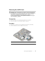
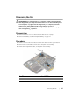
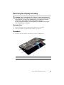
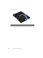
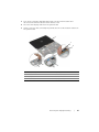
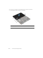
1
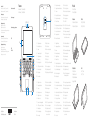
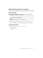
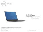
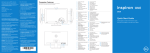
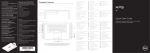
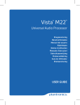
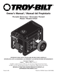
1 Connect the power adapter and
press the power button
11
Sluit de netadapater aan en druk op de aan-uitknop
Connecter l’adaptateur d’alimentation et appuyer sur le
bouton Marche/Arrêt
Netzadapter anschließen und Betriebsschalter drücken
Collegare l’adattatore di alimentazione e premere l’Accensione
2 Complete Windows setup
Shortcut Keys
Voltooi de Windows-installatie | Terminer l’installation de Windows
Windows-Setup abschließen | Completare installazione di Windows
Enable security
Schakel de beveiliging in
Activer la sécurité
Sicherheit aktivieren
Abilitare sicurezza
Quick Start Guide
Snelstartgids
Guide d’information rapide
Schnellstart-Handbuch
Guida introduttiva rapida
Sneltoetsen | Raccourcis clavier
Tastaturbefehle | Tasti di scelta rapida
Mute audio
Geluid dempen | Couper le son
Audio stummschalten | Disattiva audio
Decrease volume
Volume verlagen | Diminuer le volume
Lautstärke verringern | Diminuisci volume
Increase volume
Volume verhogen | Augmenter le volume
Lautstärke erhöhen | Aumenta volume
Play/Pause
Afspelen/Pauzeren | Lire/Pause
Wiedergabe/Pause | Riproduci/Metti in pausa
3 Explore resources
Verken de bronnen | Explorer les ressources
Ressourcen durchsuchen | Esplorare risorse
Help and Tips
Hulp en tips | Aide et astuces
Hilfe und Tipps | Assitenza e suggerimenti
My Dell
Mijn Dell | Mon Dell
Mein Dell | My Dell
Dell Shop
Dell Shop | Boutique Dell
Dell Shop | Negozio Dell
Open Search charm
Charm Zoeken openen | Ouvrir l’icône Rechercher
Charm Suche öffnen | Apri Accesso alla ricerca
Open Share charm
Charm Delen openen | Ouvrir l’icône Partager
Charm Teilen öffnen | Apri Accesso alla condivisione
Open Devices charm
Charm Apparaten openen | Ouvrir l’icône Périphériques
Charm Geräte öffnen | Apri Accesso ai dispositivi
Open Settings charm
Charm Instellingen openen | Ouvrir l’icône Paramètres
Charm Einstellungen öffnen | Apri Accesso alle impostazioni
List recently used apps
Lijst van onlangs gebruikte apps
Liste des apps récemment utilisées
Kürzlich verwendete Apps auflisten
Elenca le app utilizzate di recente
Change keyboard settings
Toetsenbordinstellingen wijzigen
Modifier les paramètres du clavier
Tastatureinstellungen ändern
Modifica impostazioni tastiera
Decrease brightness
Helderheid verminderen | Diminuer la luminosité
Reduzieren der Helligkeit | Ridurre luminosità
Increase brightness
Helderheid vermeerderen | Augmenter la luminosité
Erhöhen der Helligkeit | Aumentare luminosità
Turn off/on wireless
Draadloos in-/uitschakelen | Activer/désactiver le sans fil
Wireless ein/ausschalten | Attiva/Disattiva modalità senza fili
NOTE: For more information, see Specifications at dell.com/support.
N.B.: Ga voor meer informatie naar Specificaties op dell.com/support.
REMARQUE : Pour plus d’informations, consulter la section Spécifications
sur dell.com/support.
ANMERKUNG: Weitere Informationen finden Sie in Technische Daten unter
dell.com/support.
N.B.: per maggiori informazioni consultare Specifiche su dell.com/support.
Contact Dell
Neem contact op met Dell | Contacter Dell
Kontaktaufnahme mit Dell | Contattare Dell
dell.com/contactdell
Product support
Productondersteuning | Support produits
Produktsupport | Supporto prodotto
dell.com/support
Regulatory and safety
Regelgeving en veiligheid
Réglementations et sécurité
Sicherheitshinweise und Zulassungsinformationen
Conformità e sicurezza
Computer model
Computermodel | Modèle de l’ordinateur
Computermodell | Modello computer
Regulatory model and type
Wettelijk model en type
Modèle et type réglementaires
Muster-Modellnummer und Muster-Typnummer
Modello e tipo di conformità
Features
Kenmerken | Fonctionnalités
Funktionen | Caratteristiche
1
21
2 3 4 5
dell.com/regulatory_compliance
1. Microphone numérique
12. Zone de clic droit
2. Capteur de lumière d’ambiance
13. Zone de clic gauche
3. Caméra
14. Boutons de contrôle du volume
4. Voyant d’état de la caméra
15. Haut-parleur gauche
5. Microphone numérique
16. Port pour casque
6. Touche Windows
17. Port HDMI
7. Emplacement pour câble de sécurité
18. Port USB 3.0 avec PowerShare
8. Port USB 3.0 avec PowerShare
19. Port de l’adaptateur secteur
9. Lecteur de carte mémoire
20. Microphones numériques (2)
10. Haut-parleur droit
11. Bouton d’alimentation
9P33
20
P16T
P16T001
6
7
19
18
8
17
16
9
1. Digital microphone
12. Right-click area
1. Digitales Mikrofon
12. Rechter Mausklickbereich
13. Left-click area
2. Umgebungslichtsensor
13. Linker Mausklickbereich
3. Camera
14. Volume-control buttons
3. Kamera
14. Tasten zur Lautstärkeregelung
4. Camera-status light
15. Left speaker
4. Kamerastatusanzeige
15. Linker Lautsprecher
5. Digital microphone
16. Headset port
5. Digitales Mikrofon
16. Kopfhöreranschluss
6. Windows key
17. HDMI port
6. Windows-Taste
17. HDMI-Anschluss
7. Security-cable slot
18. USB 3.0 port with PowerShare
7. Sicherheitskabeleinschub
18. USB 3.0-Anschluss mit PowerShare
8. USB 3.0 port with PowerShare
19. Power-adapter port
8. USB 3.0-Anschluss mit PowerShare
19. Netzadapteranschluss
9. Media-card reader
20. Digital microphones (2)
9. Speicherkartenlesegerät
20. Digitale Mikrofone (2)
15
10
14
13
12
11
21. Regulatory and Service Tag labels
11. Power button
10. Rechter Lautsprecher
11. Betriebsschalter
21. Service-Tag-Nummer und
Normierungsschilder
1. Digitale microfoon
12. Gebied voor rechtsklikken
1. Microfono digitale
12. Area per clic con pulsante destro
2. Omgevingslichtsensor
13. Gebied voor linksklikken
2. Sensore di luminosità ambientale
13. Area per clic con pulsante sinistro
3. Camera
14. Volumeknoppen
3. Fotocamera
14. Pulsanti controllo volume
4. Statuslampje camera
15. Linkerluidspreker
4. Indicatore di stato della fotocamera
15. Altoparlante sinistro
5. Digitale microfoon
16. Headsetpoort
5. Microfono digitale
16. Porta auricolare
6. Windows-toets
17. HDMI-poort
6. Tasto logo di Windows
17. Porta HDMI
7. Sleuf voor beveiligingskabel
18. USB 3.0-poort met PowerShare
7. Slot cavo di protezione
18. Porta USB 3.0 con PowerShare
8. USB 3.0-poort met PowerShare
19. Poort voor netadapter
8. Porta USB 3.0 con PowerShare
19. Porta adattatore di alimentazione
9. Lettore scheda multimediale
20. Microfoni digitali (2)
9. Mediakaartlezer
© 2013 Dell Inc.
Printed in China.
10. Rechterluidspreker
© 2013 Microsoft Corporation.
2013-08
11. Aan-uitknop
20. Digitale microfoons (2)
21. Serviceplaatje en labels
met voorschriften
10. Altoparlante destro
11. Accensione
Modi | Modes
Modi | Modalità
Notebook
Notebook | Notebook
Notebook | Notebook
Tablet
Tablet | Tablette
Tablet | Tablet
Tablet Stand
Tablet Staand
Station d’accueil
Tablet-Standrahmen
Supporto tablet
Tent
Tent | Tente
Zelt | Tent
21. Numéro de service et étiquettes
de conformité aux normes
2. Ambient-light sensor
10. Right speaker
Modes
21. Etichette Numero di servizio
e conformità
XPS 11
Service Manual
Computer model: XPS 9P33
Regulatory model: P16T
Regulatory type: P16T001
Notes, Cautions, and Warnings
NOTE: A NOTE indicates important information that helps you make better
use of your computer.
CAUTION: A CAUTION indicates potential damage to hardware or loss of
data if instructions are not followed.
WARNING: A WARNING indicates a potential for property damage,
personal injury, or death.
____________________
© 2013 Dell Inc.
Trademarks used in this text: Dell™, the DELL logo, and XPS™ are trademarks of Dell Inc.
2013 - 10
Rev. A00
Contents
Before Working Inside Your Computer
Before You Begin
Recommended Tools
Safety Instructions
5
5
5
6
After Working Inside Your Computer
7
Removing the Base Cover
8
Procedure
Replacing the Base Cover
Procedure
Removing the Battery
Prerequisites
Procedure
Replacing the Battery
Procedure
Postrequisites
Removing the Wireless Card
Prerequisites
Procedure
Replacing the Wireless Card
Procedure
Postrequisites
Removing the mSATA Card
Prerequisites
Procedure
Replacing the mSATA Card
Procedure
Postrequisites
8
10
10
11
11
11
12
12
12
13
13
13
14
14
14
15
15
15
16
16
16
Contents
|
3
Removing the Fan
17
Prerequisites
Procedure
17
17
Replacing the Fan
18
Procedure
Postrequisites
Removing the Display Assembly
Prerequisites
Procedure
Replacing the Display Assembly
Procedure
Postrequisites
Removing the System Board
Prerequisites
Procedure
Replacing the System Board
Procedure
Postrequisites
Entering the Service Tag in the BIOS
Removing the Palm-Rest Assembly
Prerequisites
Procedure
Replacing the Palm-Rest Assembly
Procedure
Postrequisites
Flashing the BIOS
4
|
Contents
18
18
19
19
19
23
23
23
24
24
24
30
30
30
30
31
31
31
33
33
33
34
Before Working Inside Your Computer
Before You Begin
CAUTION: To avoid data loss, save and close all open files and exit all open
programs before turning off your computer.
1
Save and close all open files, exit all open programs, and turn off your computer.
Point to the lower or upper-right corner of the screen to open the charms sidebar
and click Settings→ Power→ Shut down.
NOTE: If you are using a different operating system, see the documentation of
your operating system for shut-down instructions.
2
After the computer shuts down, disconnect it from the electrical outlet.
3
Disconnect all cables — such as power and USB cables — from your computer.
4
Disconnect all peripherals, including media cards, connected to your computer.
Recommended Tools
The procedures in this document require the following tools:
•
Phillips screwdriver
•
Torx #5 (T5) screwdriver
•
Plastic scribe
Before Working Inside Your Computer
|
5
Safety Instructions
Use the following safety guidelines to protect your computer from potential damage and
ensure your personal safety.
WARNING: Before working inside your computer, read the safety
information that shipped with your computer. For more safety best practices,
see the Regulatory Compliance home page at dell.com/regulatory_compliance.
WARNING: Disconnect all power sources before opening the computer
cover or panels. After you finish working inside the computer, replace all covers,
panels, and screws before connecting to the power source.
CAUTION: Only a certified service technician is authorized to remove the
computer cover and access any of the components inside the computer. See the
safety instructions for complete information about safety precautions, working
inside your computer, and protecting against electrostatic discharge.
CAUTION: To avoid damaging the computer, make sure that the work surface is
flat and clean.
CAUTION: Before touching anything inside your computer, ground yourself
by touching an unpainted metal surface, such as the metal at the back of the
computer. While you work, periodically touch an unpainted metal surface to
dissipate static electricity, which could harm internal components.
CAUTION: When you disconnect a cable, pull on its connector or on its pull-tab,
not on the cable itself. Some cables have connectors with locking tabs or
thumb-screws that you must disengage before disconnecting the cable.
When disconnecting cables, keep them evenly aligned to avoid bending any
connector pins. When connecting cables, make sure that the ports and
connectors are correctly oriented and aligned.
CAUTION: To avoid damaging the components and cards, handle them by
their edges and avoid touching pins and contacts.
CAUTION: Press and eject any installed card from the media-card reader.
6
|
Before Working Inside Your Computer
After Working Inside Your Computer
CAUTION: Leaving stray or loose screws inside your computer may severely
damage your computer.
1
Replace all screws and make sure that no stray screws remain inside your
computer.
2
Connect any cables, peripherals, and other parts you removed before working on
your computer.
3
Connect your computer to the electrical outlet.
4
Turn on your computer.
After Working Inside Your Computer
|
7
Removing the Base Cover
WARNING: Before working inside your computer, read the safety information
that shipped with your computer and follow the steps in "Before Working Inside
Your Computer" on page 5. After working inside your computer, follow the
instructions in "After Working Inside Your Computer" on page 7.
For more safety best practices, see the Regulatory Compliance home page at
dell.com/regulatory_compliance.
Procedure
1
Close the display, and turn the computer over.
2
Release the system badge and turn it over.
2
1
1
8
|
base cover
Removing the Base Cover
2
system badge
3
Remove the screws that secure the base cover to the palm-rest assembly.
4
Loosen the captive screws that secure the base cover to the palm-rest assembly.
1
2
3
4
5
1
screws (Torx) (6)
2
base cover
3
captive screws (4)
4
screw (Phillips)
Place the computer with the rear side facing you, and gently pry up the base cover.
Removing the Base Cover
|
9
Replacing the Base Cover
WARNING: Before working inside your computer, read the safety information
that shipped with your computer and follow the steps in "Before Working Inside
Your Computer" on page 5. After working inside your computer, follow the
instructions in "After Working Inside Your Computer" on page 7.
For more safety best practices, see the Regulatory Compliance home page at
dell.com/regulatory_compliance.
Procedure
1
Place the base cover on the palm-rest assembly and snap the base cover into place.
2
Tighten the captive screws that secure the base cover to the palm-rest assembly.
3
Replace the screws that secure the base cover to the palm-rest assembly.
4
Turn the system badge over and snap it into place.
10
|
Replacing the Base Cover
Removing the Battery
WARNING: Before working inside your computer, read the safety information
that shipped with your computer and follow the steps in "Before Working Inside
Your Computer" on page 5. After working inside your computer, follow the
instructions in "After Working Inside Your Computer" on page 7.
For more safety best practices, see the Regulatory Compliance home page at
dell.com/regulatory_compliance.
Prerequisites
Remove the base cover. See "Removing the Base Cover" on page 8.
Procedure
1
Disconnect the battery cable from the system board.
2
Remove the screws that secure the battery to the palm-rest assembly.
3
Lift the battery, along with its cable, off the palm-rest assembly.
1
2
3
4
4
1
battery cable
2
screws (3)
3
battery
4
palm-rest assembly
Turn the computer over, open the display, and press the power button for about
five seconds to ground the system board.
Removing the Battery
|
11
Replacing the Battery
WARNING: Before working inside your computer, read the safety information
that shipped with your computer and follow the steps in "Before Working Inside
Your Computer" on page 5. After working inside your computer, follow the
instructions in "After Working Inside Your Computer" on page 7.
For more safety best practices, see the Regulatory Compliance home page at
dell.com/regulatory_compliance.
Procedure
1
Close the display and turn the computer over.
2
Align the screw holes on the battery with the screw holes on the
palm-rest assembly.
3
Replace the screws that secure the battery to the palm-rest assembly.
4
Connect the battery cable to the system board.
Postrequisites
Replace the base cover. See "Replacing the Base Cover" on page 10.
12
|
Replacing the Battery
Removing the Wireless Card
WARNING: Before working inside your computer, read the safety information
that shipped with your computer and follow the steps in "Before Working Inside
Your Computer" on page 5. After working inside your computer, follow the
instructions in "After Working Inside Your Computer" on page 7.
For more safety best practices, see the Regulatory Compliance home page at
dell.com/regulatory_compliance.
Prerequisites
1
Remove the base cover. See "Removing the Base Cover" on page 8.
2
Remove the battery. See "Removing the Battery" on page 11.
Procedure
1
Peel off the conductive tape that covers the antenna cables.
2
Disconnect the antenna cables from the wireless card.
3
Remove the screw that secures the wireless card to the system board.
4
Slide and remove the wireless card out of the wireless-card connector.
2
3
4
1
5
1
conductive tape
2
screw
3
antenna cables (2)
4
wireless card
5
wireless-card connector
Removing the Wireless Card
|
13
Replacing the Wireless Card
WARNING: Before working inside your computer, read the safety information
that shipped with your computer and follow the steps in "Before Working Inside
Your Computer" on page 5. After working inside your computer, follow the
instructions in "After Working Inside Your Computer" on page 7.
For more safety best practices, see the Regulatory Compliance home page at
dell.com/regulatory_compliance.
Procedure
CAUTION: To avoid damaging the wireless card, do not place any cables under it.
1
Align the notch on the wireless card with the tab on the wireless-card connector.
2
Insert the wireless card at an angle into the wireless-card connector.
3
Press the other end of the wireless card down and replace the screw that secures
the wireless card to the system board.
4
Connect the antenna cables to the wireless card.
The following table provides the antenna-cable color scheme for the wireless card
supported by your computer.
5
Connectors on the wireless card
Antenna-cable color
Main (white triangle)
white
Auxiliary (black triangle)
black
Adhere the conductive tape to the antenna cables.
Postrequisites
1
Replace the battery. See "Replacing the Battery" on page 12.
2
Replace the base cover. See "Replacing the Base Cover" on page 10.
14
|
Replacing the Wireless Card
Removing the mSATA Card
WARNING: Before working inside your computer, read the safety information
that shipped with your computer and follow the steps in "Before Working Inside
Your Computer" on page 5. After working inside your computer, follow the
instructions in "After Working Inside Your Computer" on page 7.
For more safety best practices, see the Regulatory Compliance home page at
dell.com/regulatory_compliance.
Prerequisites
1
Remove the base cover. See "Removing the Base Cover" on page 8.
2
Remove the battery. See "Removing the Battery" on page 11.
Procedure
1
Remove the screw that secures the mSATA card to the palm-rest assembly.
2
Slide the mSATA card out of the mSATA-card connector.
3
2
1
1
screw
3
mSATA-card connector
2
mSATA card
Removing the mSATA Card
|
15
Replacing the mSATA Card
WARNING: Before working inside your computer, read the safety information
that shipped with your computer and follow the steps in "Before Working Inside
Your Computer" on page 5. After working inside your computer, follow the
instructions in "After Working Inside Your Computer" on page 7.
For more safety best practices, see the Regulatory Compliance home page at
dell.com/regulatory_compliance.
Procedure
1
Align the notch on the mSATA card with the tab on the mSATA-card connector.
2
Insert the mSATA card at an angle into the mSATA-card connector.
3
Press the other end of the mSATA card down and replace the screw that secures
the mSATA card to the palm-rest assembly.
Postrequisites
1
Replace the battery. See "Replacing the Battery" on page 12.
2
Replace the base cover. See "Replacing the Base Cover" on page 10.
16
|
Replacing the mSATA Card
Removing the Fan
WARNING: Before working inside your computer, read the safety information
that shipped with your computer and follow the steps in "Before Working Inside
Your Computer" on page 5. After working inside your computer, follow the
instructions in "After Working Inside Your Computer" on page 7.
For more safety best practices, see the Regulatory Compliance home page at
dell.com/regulatory_compliance.
Prerequisites
1
Remove the base cover. See "Removing the Base Cover" on page 8.
2
Remove the battery. See "Removing the Battery" on page 11.
Procedure
1
Lift the connector latch and disconnect the fan cable from the system board.
2
Remove the screws that secure the fan to the palm-rest assembly.
3
Lift the fan, along with its cable, off the palm-rest assembly.
2
1
3
4
5
1
fan
2
screws (2)
3
palm-rest assembly
4
fan cable
5
connector latch
Removing the Fan
|
17
Replacing the Fan
WARNING: Before working inside your computer, read the safety information
that shipped with your computer and follow the steps in "Before Working Inside
Your Computer" on page 5. After working inside your computer, follow the
instructions in "After Working Inside Your Computer" on page 7.
For more safety best practices, see the Regulatory Compliance home page at
dell.com/regulatory_compliance.
Procedure
1
Align the screw holes on the fan with the screw holes on the palm-rest assembly.
2
Replace the screws that secure the fan to the palm-rest assembly.
3
Slide the fan cable into the system-board connector and press down on the
connector latch to secure the cable.
Postrequisites
1
Replace the battery. See "Replacing the Battery" on page 12.
2
Replace the base cover. See "Replacing the Base Cover" on page 10.
18
|
Replacing the Fan
Removing the Display Assembly
WARNING: Before working inside your computer, read the safety information
that shipped with your computer and follow the steps in "Before Working Inside
Your Computer" on page 5. After working inside your computer, follow the
instructions in "After Working Inside Your Computer" on page 7.
For more safety best practices, see the Regulatory Compliance home page at
dell.com/regulatory_compliance.
Prerequisites
1
Remove the base cover. See "Removing the Base Cover" on page 8.
2
Remove the battery. See "Removing the Battery" on page 11.
Procedure
1
Carefully rotate the palm-rest assembly to an angle of 180 degrees.
1
2
1
palm-rest assembly
2
display assembly
Removing the Display Assembly
|
19
2
Turn the computer over.
1
2
1
20
|
palm-rest assembly
Removing the Display Assembly
2
display assembly
3
Peel off the conductive and Mylar tapes that cover the antenna cables and
disconnect the antenna cables from the wireless card.
4
Disconnect the display cable from the system board.
5
Lift the connector latch, and using the pull tab, disconnect the webcam cable from
the system board.
8
7
6
5
2
4
1
3
1
conductive tape
2
Mylar tape
3
wireless card
4
antenna cables (2)
5
display cable
6
connector latch
7
webcam cable
8
display assembly
Removing the Display Assembly
|
21
6
Remove the screws that secure the display hinges to the palm-rest assembly.
7
Lift the display assembly off the palm-rest assembly.
1
2
3
4
22
1
display assembly
2
screws (6)
3
display hinges (2)
4
palm-rest assembly
|
Removing the Display Assembly
Replacing the Display Assembly
WARNING: Before working inside your computer, read the safety information
that shipped with your computer and follow the steps in "Before Working Inside
Your Computer" on page 5. After working inside your computer, follow the
instructions in "After Working Inside Your Computer" on page 7.
For more safety best practices, see the Regulatory Compliance home page at
dell.com/regulatory_compliance.
Procedure
1
Align the screw holes on the display hinges with the screw holes on the
palm-rest assembly.
2
Replace the screws that secure the display hinges to the palm-rest assembly.
3
Slide the webcam cable into the system-board connector and press down on the
connector latch to secure the cable.
4
Connect the display cable to the system board.
5
Connect the antenna cables to the wireless card.
6
Adhere the conductive and Mylar tapes to the antenna cables.
7
Turn the computer over.
8
Rotate the palm-rest assembly to an angle of 180 degrees.
Postrequisites
1
Replace the battery. See "Replacing the Battery" on page 12.
2
Replace the base cover. See "Replacing the Base Cover" on page 10.
Replacing the Display Assembly
|
23
Removing the System Board
WARNING: Before working inside your computer, read the safety information
that shipped with your computer and follow the steps in "Before Working Inside
Your Computer" on page 5. After working inside your computer, follow the
instructions in "After Working Inside Your Computer" on page 7.
For more safety best practices, see the Regulatory Compliance home page at
dell.com/regulatory_compliance.
Prerequisites
1
Remove the base cover. See "Removing the Base Cover" on page 8.
2
Remove the battery. See "Removing the Battery" on page 11.
3
Remove the wireless card. See "Removing the Wireless Card" on page 13.
4
Remove the mSATA card. See "Removing the mSATA Card" on page 15.
24
|
Removing the System Board
Procedure
NOTE: Replacing the system board removes any changes you made to the BIOS
using System Setup. Enter the Service Tag of your computer in the BIOS and make
the desired changes again after you replace the system board.
For more information on entering the Service Tag in the BIOS, see "Replacing the
System Board" on page 30.
NOTE: Before disconnecting the cables from the system board, note the location
of the connectors so that you can reconnect them correctly after you replace the
system board.
1
Peel off the adhesive foam from the keyboard and keyboard-backlight cable.
1
1
adhesive foam
Removing the System Board
|
25
2
Remove the screws that secure the display hinge to the palm-rest assembly.
2
1
3
3
1
display hinge
3
palm-rest assembly
2
screws (3)
Open the palm-rest assembly to release the display hinge and close the
palm-rest assembly.
1
2
1
26
|
palm-rest assembly
Removing the System Board
2
display assembly
4
Disconnect the power-adapter port cable from the system board.
1
2
3
4
1
display hinge
2
power-adapter port cable
3
power-adapter port
4
system board
Removing the System Board
|
27
5
Lift the connector latches, and using the pull tabs disconnect the power-button
cable, NFC cable, touchpad cable, keyboard and keyboard-backlight cable,
volume-control buttons cable, fan cable, webcam cable, and display-lid switch
cable.
6
Disconnect the speaker cable and display cable.
2
3
1
4
5
6
7
8
11
9
10
28
1
display cable
2
webcam cable
3
display-lid switch cable
4
speaker cable
5
volume-control buttons cable
6
fan cable
7
keyboard and keyboard-backlight cable
8
touchpad cable
9
NFC cable
10
power-button cable
11
connector latch
|
Removing the System Board
7
Remove the screws that secure the system board to the palm-rest assembly.
8
Lift the system board off the palm-rest assembly.
1
2
3
1
screws (6)
3
palm-rest assembly
2
system board
Removing the System Board
|
29
Replacing the System Board
WARNING: Before working inside your computer, read the safety information
that shipped with your computer and follow the steps in "Before Working Inside
Your Computer" on page 5. After working inside your computer, follow the
instructions in "After Working Inside Your Computer" on page 7.
For more safety best practices, see the Regulatory Compliance home page at
dell.com/regulatory_compliance.
Procedure
CAUTION: Make sure that no cables are placed under the system board.
1
Align the screw holes on the system board with the screw holes on the
palm-rest assembly.
2
Replace the screws that secure the system board to the palm-rest assembly.
3
Slide the power-button cable, NFC cable, touchpad cable, keyboard and
keyboard-backlight cable, volume-control buttons cable, fan cable, webcam cable,
and display-lid switch cable into the system-board connectors, and press down on
the connector latches to secure the cables.
4
Connect the speaker cable, display cable, and power-adapter port cable to the
system board.
5
Press down the display hinge in place.
6
Replace the screws that secure the display hinge to the palm-rest assembly.
Postrequisites
1
Replace the mSATA card. See "Replacing the mSATA Card" on page 16.
2
Replace the wireless card. See "Replacing the Wireless Card" on page 14.
3
Replace the battery. See "Replacing the Battery" on page 12.
4
Replace the base cover. See "Replacing the Base Cover" on page 10.
Entering the Service Tag in the BIOS
1
Turn on the computer.
2
At the Dell logo, press F2 to enter System Setup.
3
Navigate to the Main tab and type the Service Tag in the Service Tag field.
30
|
Replacing the System Board
Removing the Palm-Rest Assembly
WARNING: Before working inside your computer, read the safety information
that shipped with your computer and follow the steps in "Before Working Inside
Your Computer" on page 5. After working inside your computer, follow the
instructions in "After Working Inside Your Computer" on page 7.
For more safety best practices, see the Regulatory Compliance home page at
dell.com/regulatory_compliance.
Prerequisites
1
Remove the base cover. See "Removing the Base Cover" on page 8.
2
Remove the battery. See "Removing the Battery" on page 11.
3
Remove the mSATA card. See "Removing the mSATA Card" on page 15.
4
Remove the fan. See "Removing the Fan" on page 17.
5
Remove the system board. See "Removing the System Board" on page 24.
Procedure
1
Carefully rotate the palm-rest assembly to an angle of 180 degrees.
1
2
1
palm-rest assembly
2
display assembly
Removing the Palm-Rest Assembly
|
31
2
Turn the computer over.
1
2
1
palm-rest assembly
2
display assembly
3
Remove the screws that secure the display hinges to the palm-rest assembly.
4
Lift the display assembly away from the palm-rest assembly.
1
2
3
4
32
1
display assembly
2
screws (6)
3
display hinges (2)
4
palm-rest assembly
|
Removing the Palm-Rest Assembly
Replacing the Palm-Rest Assembly
WARNING: Before working inside your computer, read the safety information
that shipped with your computer and follow the steps in "Before Working Inside
Your Computer" on page 5. After working inside your computer, follow the
instructions in "After Working Inside Your Computer" on page 7.
For more safety best practices, see the Regulatory Compliance home page at
dell.com/regulatory_compliance.
Procedure
1
Align the screw holes on the display hinges with the screw holes on the
palm-rest assembly.
2
Replace the screws that secure the display hinges to the palm-rest assembly.
3
Turn the computer over.
4
Rotate the palm-rest assembly to an angle of 180 degrees.
Postrequisites
1
Replace the system board. See "Replacing the System Board" on page 30.
2
Replace the fan. See "Replacing the Fan" on page 18.
3
Replace the mSATA card. See "Replacing the mSATA Card" on page 16.
4
Replace the battery. See "Replacing the Battery" on page 12.
5
Replace the base cover. See "Replacing the Base Cover" on page 10.
Replacing the Palm-Rest Assembly
|
33
Flashing the BIOS
You may need to flash (update) the BIOS when an update is available or when you
replace the system board. To flash the BIOS:
1
Turn on the computer.
2
Go to dell.com/support.
3
If you have your computer's Service Tag, type your computer's Service Tag and
click Submit.
If you do not have your computer's Service Tag, click Detect Service Tag to allow
automatic detection of the Service Tag.
NOTE: If the Service Tag cannot be detected automatically, select your
product under the product categories.
4
Click Drivers & Downloads.
5
In the Operating System drop-down, select the operating system installed on
your computer.
6
Click BIOS.
7
Click Download File to download the latest version of the BIOS for your computer.
8
Save the file and once the download is complete, navigate to the folder where you
saved the BIOS update file.
9
Double-click the BIOS update file icon and follow the instructions on the screen.
34
|
Flashing the BIOS