1
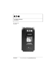
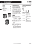
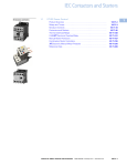
User’s Guide to IEC Type 1 and
Type 2 Coordination
Application Note
What is it?
November 2005
New Information
The International Electrotechnical Commission (IEC) developed short circuit performance criteria for contactors and
starters called Type 1 coordination and Type 2 coordination.
This defines motor controller protection levels following a
short circuit fault. In order to achieve this performance, the
combination of a motor controller (contactor or starter) and
short circuit protective device (manual motor protector, circuit breaker or fuse) must meet the following criteria as
specified by IEC 60947-4-1 — Low voltage switchgear and
controlgear — Part 4-1: Contactors and motor-starters —
Electromechanical contactors and motor-starters:
Type 1 Coordination requires that under short circuit
conditions, the contactor or starter shall cause no danger to
persons or installation and may not be suitable for further
service without repair and replacement of parts.
In this case, significant damage is allowed to the contactor/
starter (e.g. contact welding, burning, or disintegration) and
the overload relay (e.g. component harm or heater element
burn-out).
Manual Motor Controller
Type 2 Coordination requires that under short circuit
conditions, the contactor or starter shall cause no danger to
persons or installation and shall be suitable for further use.
The risk of contact welding is recognized, in which case the
manufacturer shall indicate the measures to be taken as
regards to the maintenance of the equipment.
In this case, the contactor/starter is able to continue use after
the occurrence of a short circuit fault. Light contact burning
or tack welding may occur provided the contacts are easily
separable.
Who benefits and why?
Series G Molded Case Circuit Breaker
Achieving an acceptable level of short circuit coordination
requires knowledge about the application, product
standards, installation codes and the attributes of the many
short circuit protective devices (SCPDs) that are available.
Extensive testing must be completed and certified in order
to achieve a Type 1 or 2 rating. IEC 60947-4-1 offers precise
definitions of allowable damage in order to guide users to
the right product with the right protection.
Generally speaking, most users expect Type 2 protection in
their applications. With certifying agencies varying from
country-to-country and continent-to-continent, users will
sometimes mistakenly assume that Type 2 coordination has
been achieved if their motor branch circuit components are
CE marked, UL Listed Type E or F and/or CSA Certified. This
is not necessarily true.
XT Starter
AP03407001E
For more information visit: www.EatonElectrical.com
Application Note
Page 2
User’s Guide to IEC Type 1
and Type 2 Coordination
Effective: November 2005
At the forefront of Type 2 benefits comes the assurance that
the device poses no threat of danger to the person or
installation. Furthermore, with increased emphasis placed
on reducing downtime to increase productivity, proper
application and selection of motor branch circuit devices is
more important than ever. By selecting the proper type of
protection, the working environment and employees can be
protected against hazardous fault conditions and the
performance of contactors and overload relays in the branch
circuit can be maximized.
Type 2 protection provides confidence that motor control
components will be operable following a short circuit fault. This
reusability translates into hundreds or even thousands of dollars
in savings due to reduced downtime and replacement costs.
TYPE 2 Coordination = Safety + Less Downtime = Dollars
and Cents
How does Eaton comply?
It is important to understand the short circuit testing pass/
fail criteria of the applicable product standards (UL 508,
CSA C22.2 No. 14 and IEC 60947) when specifying products
for each application. Each standard requires that devices are
capable of withstanding minimum short circuit currents
(based on the starter’s rating). UL and CSA refer to the
minimum rating as the Standard Fault Short Circuit Current
Rating. IEC 60947-4-1 and 60947-6-2 refer to these ratings as
Ir and Icr respectively.
Standard Fault Short Circuit Current Rating (Derived from
UL 508): The minimum short circuit current, based on horsepower rating, that a starter must be capable of withstanding
in accordance with the applicable pass/fail criteria. Denoted
as Ir by IEC 60947-4-1 and Icr by IEC 60947-6-2.
Manufacturers may also specify short circuit ratings
exceeding the minimum ratings required by standards. UL
and CSA refer to these as the High-Available Fault Short
Circuit Current Rating. IEC 60947-4-1 and 60947-6-2 refer to
these ratings as Iq and Ics respectively.
High-Available Fault Short Circuit Current Rating (Derived
from UL 508): The short circuit current rating specified by
the manufacturer of a motor controller, which is greater than
the standard short circuit current rating. The motor controller
is capable of withstanding the high-available short circuit
current in accordance with the applicable pass/fail criteria.
Denoted as Iq by IEC 60947-4-1 and I cs by IEC 60947-6-2.
Following is a summary of short circuit testing pass/fail
criteria applicable to magnetically operated direct-on-line
contactors and starters. Standards should be referenced for
exact wording and all specific pass/fail criteria. UL and IEC
criteria are summarized for standard and high-available
short circuit currents. CSA criteria are summarized for highavailable short circuit currents.
Table 1. Defining Pass/Fail Criteria: UL 508/CSA C22.2 No. 14 and IEC 60947-4-1
UL and CSA
IEC 60947-4-1
Type 1
Fault Current
Enclosure
Type 2
Fault current is successfully interrupted and no arcing to enclosure or proximity barrier is
indicated by an open ground wire or fuselink.
No substantial damage to the enclosure. It may be deformed but it must be possible to open the door.
Live parts shall not be accessible.
Terminals and Conductors
No damage to conductors or terminals. Conductors must not be separated from the terminals.
Contactor/Starter Housing
No cracking or breaking of the contactor/starter housing that impairs the integrity of the mounting of live parts.
Short Circuit Protective Device
(SCPD)
The circuit breaker or switch must be capable of being operated manually.
SCPD is not separated from its mounting means. Fuses must not rupture.
Contactor/Starter Contacts
Welding and complete disintegration acceptable.
Welding acceptable.
Welding acceptable provided contacts can be easily separated.
Overload Relay
Electronic overload relays must be
operable; tripping characteristics
must be verified (UL). Mechanical
overload relays may be damaged, if
so, device must include markings
indicating that (UL).
Damage acceptable.
No damage, tripping characteristics
must be verified.
Contactor/Starter Operation
May be inoperable.
May be inoperable.
Must be operable, verified by 10
operations after short circuit test.
Other
No discharge of parts from enclosure. No risk of fire.
No discharge of parts from enclosure. Must pass 2X rated voltage,
1000V minimum dielectric test.
No discharge of parts from enclosure. Must pass 2X rated voltage,
1000V minimum dielectric test.
For more information visit: www.EatonElectrical.com
AP03407001E
User’s Guide to IEC Type 1
and Type 2 Coordination
Application Note
Effective: November 2005
Page 3
What branch circuit devices do you need for Type 2?
Achieving Type 2 is straightforward when using the following selection tables. Follow these steps to ensure that Type 2
coordination is in place:
Step 1: Determine the motor Horsepower or kW (single or
three phase) or full load motor current from the
motor nameplate.
Note: For certain horsepowers at 480V and 600V, a current limiter
must be used to achieve the maximum Type 2 rating (shown in the
following tables). Customers can either order the MMP and Current
Limit Contactors or an assembled MMC and current limiter.
Step 2: Verify the motor full load amps are less than or
equal to the operational current (Ie) listed next to the
hp or kW in the table.
Circuit breaker combination controllers: Read across
the tables horizontally to determine the catalog
numbers of the circuit breaker to be used in
conjunction with the contactor and overload relay
listed (customer assembly) or the pre-assembled
motor starter.
Step 3: Manual Motor Controllers (MMC): Read across the
tables horizontally for catalog numbers of the
Manual Motor Protector (MMP) and contactor (customer assembly) or pre-assembled Manual Motor
Controller.
Fused combination controllers: Read across the
tables horizontally to determine what amperage size
fuse (customer to specify brand) and the catalog
numbers of the contactor and overload relay or the
pre-assembled motor starter.
Manual Motor Controller Combinations
Table 2. 400/415V Type 2 Coordination — MMC
P
(kW)
Ie
(A)
Iq
(kA)
MMP
Catalog Number
Contactor
Catalog Number MMC
Catalog Number 0.06
0.09
0.12
0.18
0.25
0.37
0.55
0.75
1.10
1.50
2.20
3.00
4.00
5.50
7.50
11.00
15.00
0.21
0.31
0.41
0.60
0.80
1.10
1.50
1.90
2.60
3.60
5.00
6.60
8.50
11.30
16.00
21.70
29.30
50.00 (150.00) 50.00 (150.00) 50.00 (150.00) 50.00 (150.00) 50.00 (150.00) 50.00 (150.00) 50.00 (150.00) 50.00 (150.00) 50.00 (150.00) 50.00 (150.00) 50.00 (150.00) 50.00 (150.00) 50.00 (150.00) 50.00
50.00
50.00
50.00
XTPRP25BC1
XTPRP40BC1
XTPRP63BC1
XTPRP63BC1
XTPR001BC1
XTPR1P6BC1
XTPR1P6BC1
XTPR2P5BC1
XTPR004BC1
XTPR004BC1
XTPR6P3BC1
XTPR010BC1
XTPR010BC1
XTPR012BC1
XTPR016BC1
XTPR025BC1
XTPR032BC1
XTCE007B10_
XTCE007B10_
XTCE007B10_
XTCE007B10_
XTCE007B10_
XTCE007B10_
XTCE007B10_
XTCE007B10_
XTCE007B10_
XTCE007B10_
XTCE007B10_
XTCE018C10_
XTCE018C10_
XTCE018C10_
XTCE018C10_
XTCE025C10_
XTCE032C10_
XTSCP25BB_
XTSCP40BB_
XTSCP63BB_
XTSCP63BB_
XTSC001BB_
XTSC1P6BB_
XTSC1P6BB_
XTSC2P5BB_
XTSC004BB_
XTSC004BB_
XTSC6P3BB_
XTSC010BC_
XTSC010BC_
XTSC012BC_
XTSC016BC_
XTSC025BC_
XTSC032BC_
5.50
7.50
11.00
15.00
18.50
22.00
30.00
34.00
11.30
16.00
21.70
29.30
36.00
41.00
55.00
63.00
50.00
50.00
50.00
50.00
50.00
50.00
50.00
50.00
XTPR016DC1
XTPR016DC1
XTPR025DC1
XTPR032DC1
XTPR040DC1
XTPR050DC1
XTPR058DC1
XTPR063DC1
XTCE018C10_
XTCE018C10_
XTCE025C10_
XTCE032C10_
XTCE040D00_
XTCE050D00_
XTCE065D00_
XTCE065D00_
XTSC016DC_
XTSC016DC_
XTSC025DC_
XTSC032DC_
XTSC040DD_
XTSC050DD_
XTSC058DD_
XTSC063DD_
Values in parentheses ( ) are for Type 1 Coordination.
Underscore (_) indicates magnet coil suffix required. See Table 9, Page 7.
AP03407001E
For more information visit: www.EatonElectrical.com
Application Note
Page 4
Effective: November 2005
User’s Guide to IEC Type 1
and Type 2 Coordination
Table 3. 480V Type 2 Coordination — MMC
P
(hp)
Ie
(A)
Iq
(kA)
MMP
Catalog Number
1/2
1/2
1/2
1/2
1/2
3/4
1
2
2
3
3
7-1/2
7-1/2
10
10
0.24
0.32
0.51
0.74
0.94
1.32
1.72
2.55
3.10
4.55
6.15
8.40
11.00
14.50
20.00
65.00
65.00
65.00
65.00
65.00
65.00
65.00
65.00
65.00
65.00 (50.00) 65.00 (50.00) 65.00 (50.00) 65.00 (50.00) 65.00 (50.00) 65.00 (50.00) XTPRP25BC1
XTPRP40BC1
XTPRP63BC1
XTPR001BC1
XTPR001BC1
XTPR1P6BC1
XTPR2P5BC1
XTPR004BC1
XTPR004BC1
XTPR6P3BC1
XTPR6P3BC1
XTPR010BC1
XTPR012BC1
XTPR016BC1
XTPR020BC1
20
25
25
30 20.00
27.00
32.00
65.00
65.00
65.00
37.50
50.50
64.00
65.00
65.00
65.00
30 40 Current Limiter
Catalog Number
Contactor
Catalog Number MMC
Catalog Number XTPAXCL
XTPAXCL
XTPAXCL
XTPAXCL
XTPAXCL
XTPAXCL
XTCE007B10_
XTCE007B10_
XTCE007B10_
XTCE007B10_
XTCE007B10_
XTCE007B10_
XTCE018C10_
XTCE018C10_
XTCE018C10_
XTCE018C10_
XTCE018C10_
XTCE018C10_
XTCE018C10_
XTCE018C10_
XTCE025C10_
XTSCP25BB_
XTSCP40BB_
XTSCP63BB_
XTSC001BB_
XTSC001BB_
XTSC1P6BB_
XTSC2P5BC_
XTSC004BC_
XTSC004BC_
XTSC6P3BC_
XTSC6P3BC_
XTSC010BC_
XTSC012BC_
XTSC016BC_
XTSC020BC_
XTPR025DC1
XTPR032DC1
XTPR032DC1
XTCE040D00_
XTCE040D00_
XTCE040D00_
XTSC025DD_
XTSC032DD_
XTSC032DD_
XTPR040DC1
XTPR058DC1
XTPR063DC1
XTCE040D00_
XTCE065D00_
XTCE065D00_
XTSC040DD_
XTSC058DD_
XTSC063DD_
Current Limiter
Catalog Number
Contactor
Catalog Number MMC
Catalog Number XTPAXCL
XTPAXCL
XTPAXCL
XTPAXCL
XTPAXCL
XTCE007B10_
XTCE007B10_
XTCE007B10_
XTCE007B10_
XTCE007B10_
XTCE007B10_
XTCE007B10_
XTCE018C10_
XTCE018C10_
XTCE018C10_
XTCE018C10_
XTCE018C10_
XTCE018C10_
XTCE018C10_
XTCE018C10_
XTSCP25BB_
XTSCP40BB_
XTSCP63BB_
XTSCP63BB_
XTSC001BB_
XTSC1P6BB_
XTSC1P6BB_
XTSC2P5BC_
XTSC2P5BC_
XTSC004BC_
XTSC6P3BC_
XTSC010BC_
XTSC010BC_
XTSC012BC_
XTSC016BC_
Pending UL approval.
Values in parentheses ( ) are achieved without the current limiter.
Underscore (_) indicates magnet coil suffix required. See Table 9, Page 7.
Table 4. 600V Type 2 Coordination — MMC
P
(hp)
1/2
1/2
1/2
1/2
1/2
1
1
1-1/2
1-1/2
3
5
10
10
10
10
25
30
30
40 40 50 Ie
(A)
Iq
(kA)
MMP
Catalog Number
0.19
0.26
0.41
0.59
0.75
1.06
1.38
2.04
2.48
3.64
4.92
6.72
8.60
11.50
16.00
50.00
50.00
50.00
50.00
50.00
50.00
50.00
50.00
50.00
50.00
50.00 (18.00) 50.00 (18.00) 50.00 (18.00) 50.00 (18.00) 50.00 (18.00) XTPRP25BC1
XTPRP40BC1
XTPRP63BC1
XTPRP63BC1
XTPR001BC1
XTPR1P6BC1
XTPR1P6BC1
XTPR2P5BC1
XTPR2P5BC1
XTPR004BC1
XTPR6P3BC1
XTPR010BC1
XTPR010BC1
XTPR012BC1
XTPR016BC1
21.50
25.50
30.00
50.00
50.00
50.00
XTPR025DC1
XTPR032DC1
XTPR032DC1
XTCE040D00_
XTCE040D00_
XTCE040D00_
XTSC025DD_
XTSC032DD_
XTSC032DD_
40.50
51.00
61.00
50.00
42.00
42.00
XTPR050DC1
XTPR058DC1
XTPR063DC1
XTCE050D00_
XTCE065D00_
XTCE065D00_
XTSC050DD_
XTSC058DD_
XTSC063DD_
Pending UL approval.
Values in parentheses ( ) are achieved without the current limiter.
Underscore (_) indicates magnet coil suffix required. See Table 9, Page 7.
For more information visit: www.EatonElectrical.com
AP03407001E
User’s Guide to IEC Type 1
and Type 2 Coordination
Application Note
Effective: November 2005
Page 5
Contactor and Overload Relay (Motor Starter) with Fused Disconnect
Table 5. 400/415V Type 2 Coordination — Contactor and Overload Relay (Motor Starter) with Fused Disconnect
P
(kW)
Ie
(A)
Iq
(kA)
Fuses
Class gG/gL
Contactor
Catalog Number Overload Relay
Catalog Number
Assembled Starter
Catalog Number 0.12
0.18
0.25
0.37
0.55
0.75
1.10
1.50
2.20
3.00
4.00
5.50
7.50
11.00
15.00
18.50
22.00
30.00
37.00
45.00
55.00
75.00
90.00
110.00
132.00
0.41
0.60
0.80
1.10
1.50
1.90
2.60
3.60
5.00
6.60
8.50
11.30
16.00
21.70
29.30
36.00
41.00
55.00
68.00
81.00
99.00
134.00
161.00
196.00
231.00
100.00
100.00
100.00
100.00
100.00
100.00
100.00
100.00
100.00
100.00
100.00
100.00
100.00
100.00
100.00
100.00
100.00
100.00
100.00
100.00
100.00
100.00
100.00
100.00
100.00
2
2
4
4
4
6
6
6
10
16
20
25
32
40
63
63
80
100
125
160
200
200
250
315
400
XTCE007B10_
XTCE007B10_
XTCE007B10_
XTCE007B10_
XTCE007B10_
XTCE007B10_
XTCE007B10_
XTCE007B10_
XTCE007B10_
XTCE007B10_
XTCE009B10_
XTCE018C10_
XTCE018C10_
XTCE025C10_
XTCE032C10_
XTCE040D00_
XTCE050D00_
XTCE065D00_
XTCE080F00_ XTCE095F00_ XTCE115G00_ XTCE150G00_ XTCE185L22_
XTCE225L22_
XTCE250L22_
XTOBP60BC1
XTOB001BC1
XTOB001BC1
XTOB1P6BC1
XTOB1P6BC1
XTOB2P4BC1
XTOB004BC1
XTOB004BC1
XTOB006BC1
XTOB010BC1
XTOB010BC1
XTOB016CC1
XTOB016CC1
XTOB024CC1
XTOB032CC1
XTOB040DC1
XTOB057DC1
XTOB057DC1
XTOB070GC1 XTOB100GC1 XTOB100GC1 XTOB150GC1 XTOB220LC1
XTOB220LC1
XTOB250LC1
XTAE007B10_P60
XTAE007B10_001
XTAE007B10_001
XTAE007B10_1P6
XTAE007B10_1P6
XTAE007B10_2P4
XTAE007B10_004
XTAE007B10_004
XTAE007B10_006
XTAE007B10_010
XTAE009B10_010
XTAE018C10_016
XTAE018C10_016
XTAE032C10_024
XTAE032C10_032
XTAE040D00_040
XTAE065D00_057
XTAE065D00_057
XTAE080F00_070 XTAE095F00_100 XTAE115G00_100 XTAE150G00_150 XTAE185L22_220
XTAE225L22_220
XTAE250L22_250
Underscore (_) indicates magnet coil code required. See Table 9, Page 7.
Contactor frames F and G to be released in December 2005. Contact Eaton Corporation for final Type 2 combinations.
Table 6. 500V Type 2 Coordination — Contactor and Overload Relay (Motor Starter) with Fused Disconnect
P
(kW)
Ie
(A)
Iq
(kA)
Fuses
Class gG/gL
Contactor
Catalog Number Overload Relay
Catalog Number
Assembled Starter
Catalog Number 0.12
0.18
0.25
0.37
0.55
0.75
1.10
1.50
2.20
3.00
4.00
5.50
7.50
11.00
15.00
18.50
22.00
30.00
37.00
45.00
55.00
75.00
90.00
110.00
132.00
160.00
0.33
0.48
0.70
0.90
1.20
1.50
2.10
2.90
4.00
5.30
6.80
9.00
12.10
17.40
23.40
28.90
33.00
44.00
54.00
65.00
79.00
107.00
129.00
157.00
184.00
224.00
100.00
100.00
100.00
100.00
100.00
100.00
100.00
100.00
100.00
100.00
100.00
100.00
100.00
100.00
100.00
100.00
100.00
100.00
100.00
100.00
100.00
100.00
100.00
100.00
100.00
100.00
2
2
2
2
4
4
6
6
10
16
16
20
25
32
50
50
63
80
100
125
160
200
200
250
250
315
XTCE007B10_
XTCE007B10_
XTCE007B10_
XTCE007B10_
XTCE007B10_
XTCE007B10_
XTCE007B10_
XTCE007B10_
XTCE007B10_
XTCE009B10_
XTCE009B10_
XTCE012B10_
XTCE018C10_
XTCE025C10_
XTCE040D00_
XTCE040D00_
XTCE050D00_
XTCE065D00_
XTCE080F00_ XTCE095F00_ XTCE115G00_ XTCE185L22_
XTCE185L22_
XTCE185L22_
XTCE185L22_
XTCE225L22_
XTOBP40BC1
XTOBP60BC1
XTOB001BC1
XTOB001BC1
XTOB1P6BC1
XTOB1P6BC1
XTOB2P4BC1
XTOB004BC1
XTOB006BC1
XTOB006BC1
XTOB010BC1
XTOB010BC1
XTOB016CC1
XTOB024CC1
XTOB024DC1
XTOB040DC1
XTOB040DC1
XTOB057DC1
XTOB070GC1 XTOB070GC1 XTOB100GC1 XTOB125LC1
XTOB125LC1
XTOB160LC1
XTOB220LC1
XTOB250LC1
XTAE007B10_P40
XTAE007B10_P60
XTAE007B10_001
XTAE007B10_001
XTAE007B10_1P6
XTAE007B10_1P6
XTAE007B10_2P4
XTAE007B10_004
XTAE007B10_006
XTAE009B10_006
XTAE009B10_010
XTAE012B10_010
XTAE018C10_016
XTAE025C10_024
XTAE040D00_024
XTAE040D00_040
XTAE050D00_040
XTAE065D00_057
XTAE080F00_070 XTAE095F00_070 XTAE115G00_100 XTAE185L22_125
XTAE185L22_125
XTAE185L22_160
XTAE185L22_220
XTAE225L22_250
Underscore (_) indicates magnet coil code required. See Table 9, Page 7.
Contactor frames F and G to be released in December 2005. Contact Eaton Corporation for final Type 2 combinations.
AP03407001E
For more information visit: www.EatonElectrical.com
Application Note
Page 6
Effective: November 2005
User’s Guide to IEC Type 1
and Type 2 Coordination
Table 7. 690V Type 2 Coordination — Contactor and Overload Relay (Motor Starter) with Fused Disconnect
P
(kW)
Ie
(A)
Iq
(kA)
Fuses
Class gG/gL
Contactor
Catalog Number Overload Relay
Catalog Number
Assembled Starter
Catalog Number 0.12
0.18
0.25
0.37
0.55
0.75
1.10
1.50
2.20
3.00
4.00
5.50
7.50
11.00
15.00
18.50
22.00
30.00
37.00
45.00
55.00
75.00
90.00
110.00
132.00
160.00
0.24
0.35
0.50
0.70
0.90
1.10
1.50
2.10
2.90
3.80
4.90
6.50
8.80
12.60
17.00
20.90
23.80
32.00
39.00
47.00
58.00
78.00
93.00
114.00
134.00
162.00
100.00
100.00
100.00
100.00
100.00
100.00
100.00
100.00
100.00
100.00
100.00
100.00
100.00
100.00
100.00
100.00
100.00
100.00
100.00
100.00
100.00
100.00
100.00
100.00
100.00
100.00
1
2
2
2
4
4
4
6
10
10
16
16
20
25
32
32
50
63
80
80
100
160
160
200
250
250
XTCE007B10_
XTCE007B10_
XTCE007B10_
XTCE007B10_
XTCE007B10_
XTCE007B10_
XTCE007B10_
XTCE007B10_
XTCE007B10_
XTCE007B10_
XTCE009B10_
XTCE012B10_
XTCE018C10_
XTCE025C10_
XTCE032C10_
XTCE040D00_
XTCE040D00_
XTCE065D00_
XTCE080F00_ XTCE080F00_ XTCE080F00_ XTCE095F00_ XTCE115G00_ XTCE185L22_
XTCE185L22_
XTCE185L22_
XTOBP40BC1
XTOBP40BC1
XTOBP60BC1
XTOB001BC1
XTOB001BC1
XTOB1P6BC1
XTOB1P6BC1
XTOB2P4BC1
XTOB004BC1
XTOB004BC1
XTOB006BC1
XTOB010BC1
XTOB010CC1
XTOB016CC1
XTOB024CC1
XTOB024DC1
XTOB040DC1
XTOB040DC1
XTOB050GC1 XTOB050GC1 XTOB070GC1 XTOB100GC1 XTOB100GC1 XTOB125LC1
XTOB160LC1
XTOB220LC1
XTAE007B10_P40
XTAE007B10_P40
XTAE007B10_P60
XTAE007B10_001
XTAE007B10_001
XTAE007B10_1P6
XTAE007B10_1P6
XTAE007B10_2P4
XTAE007B10_004
XTAE007B10_004
XTAE009B10_006
XTAE012B10_010
XTAE018C10_010
XTAE025C10_016
XTAE032C10_024
XTAE040D00_024
XTAE040D00_040
XTAE065D00_040
XTAE080F00_050 XTAE080F00_050 XTAE080F00_070 XTAE095F00_100 XTAE115G00_100 XTAE185L22_125
XTAE185L22_160
XTAE185L22_220
Underscore (_) indicates magnet coil code required. See Table 9, Page 7.
Contactor frames F and G to be released in December 2005. Contact Eaton Corporation for final Type 2 combinations.
For more information visit: www.EatonElectrical.com
AP03407001E
User’s Guide to IEC Type 1
and Type 2 Coordination
Application Note
Effective: November 2005
Page 7
Contactor and Overload Relay (Motor Starter) with Circuit Breaker
Table 8. 400/415V Type 2 Coordination — Contactor and Overload Relay (Motor Starter) with Circuit Breaker P
(kW)
Ie
(A)
Iq
(kA)
Circuit
Breaker
Contactor
Catalog Number Overload Relay
Catalog Number
Assembled Starter
Catalog Number 0.12
0.18
0.25
0.37
0.55
0.75
1.10
1.50
2.20
3.00
4.00
5.50
7.50
11.00
15.00
18.50
22.00
30.00
37.00
45.00
55.00
75.00
90.00
110.00
132.00
160.00
0.41
0.60
0.80
1.10
1.50
1.90
2.60
3.60
5.00
6.60
8.50
11.30
16.00
21.70
29.30
36.00
41.00
55.00
68.00
81.00
99.00
134.00
161.00
196.00
231.00
279.00
15.00
15.00
15.00
15.00
15.00
15.00
15.00
15.00
15.00
15.00
15.00
15.00
15.00
15.00
15.00
15.00
15.00
15.00
50.00
50.00
50.00
50.00
50.00
50.00
50.00
50.00
HMCPE003A0C
HMCPE003A0C
HMCPE003A0C
HMCPE003A0C
HMCPE003A0C
HMCPE007C0C
HMCPE007C0C
HMCPE007C0C
HMCPE007C0C
HMCPE015E0C
HMCPE015E0C
HMCPE015E0C
HMCPE030H1C
HMCPE030H1C
HMCPE050K2C
HMCPE100R3C
HMCPE100R3C
HMCPE100R3C
HMCPJ250D5L
HMCPJ250F5L
HMCPJ250G5L
HMCPJ250G5L
HMCPJ250W5L
HMCPL600N
HMCPL600R
HMCPL600X
XTCE018C10_
XTCE018C10_
XTCE018C10_
XTCE018C10_
XTCE018C10_
XTCE018C10_
XTCE018C10_
XTCE018C10_
XTCE018C10_
XTCE018C10_
XTCE018C10_
XTCE018C10_
XTCE018C10_
XTCE025C10_
XTCE032C10_
XTCE040D00_
XTCE050D00_
XTCE065D00_
XTCE080F00_ XTCE095F00_ XTCE115G00_ XTCE150G00_ XTCE185L22_
XTCE300M22_
XTCE300M22_
XTCE300M22_
XTOBP60CC1
XTOB001CC1
XTOB001CC1
XTOB1P6CC1
XTOB1P6CC1
XTOB2P4CC1
XTOB004CC1
XTOB004CC1
XTOB006CC1
XTOB010CC1
XTOB010CC1
XTOB016CC1
XTOB024CC1
XTOB024CC1
XTOB032CC1
XTOB040DC1
XTOB057DC1
XTOB065DC1
XTOB070GC1 XTOB100GC1 XTOB125GC1 XTOB150GC1 XTOB220LC1
XTOT240C3S
XTOT290C3S
XTOT400C3S
XTAE018C10_P60
XTAE018C10_001
XTAE018C10_001
XTAE018C10_1P6
XTAE018C10_1P6
XTAE018C10_2P4
XTAE018C10_004
XTAE018C10_004
XTAE018C10_006
XTAE018C10_010
XTAE018C10_010
XTAE018C10_016
XTAE032C10_024
XTAE032C10_024
XTAE032C10_032
XTAE040D00_040
XTAE065D00_057
XTAE065D00_065
XTAE080F00_070 XTAE095F00_100 XTAE115G00_125 XTAE150G00_150 XTAE185L22_220
XTAE300M22_240
XTAE300M22_290
XTAE300M22_400
All Type 2 circuit breaker combinations are pending KEMA certification.
Underscore (_) indicates magnet coil code required. See Table 9.
Contactor frames F and G to be released in December 2005. Contact Eaton Corporation for final Type 2 combinations.
IMPORTANT: Additional testing at 480V, 525V, 600V, and 690V is in progress. Please contact Eaton Corporation for results.
Table 9. Magnet Coil Suffix
Coil Voltage
Suffix Code
Frame A – B
110V 50 Hz, 120V 60 Hz
220V 50 Hz, 240V 60 Hz
230V 50 Hz
24V 50/60 Hz
24V DC
415V 50 Hz, 480V 60 Hz
550V 50 Hz, 600V 60 Hz
208V 60 Hz
190V 50 Hz, 220V 60 Hz
240V 50 Hz, 277V 60 Hz
380V 50 Hz, 440V 60 Hz
400V 50 Hz
380V 60 Hz
12V 50/60 Hz
24V 50 Hz
42V 50 Hz, 48V 60 Hz
48V 50 Hz
120V DC
220V DC
12V DC
48V DC
Coil Voltage
Suffix Code
Frame C – F
A
B
F
T
TD C
D
E
G
H
L
N
P
R
U
W
Y
AD BD RD WD 110V 50 Hz, 120V 60 Hz
220V 50 Hz, 240V 60 Hz
230V 50 Hz
24V 50/60 Hz
24 – 27V DC
415V 50 Hz, 480V 60 Hz
550V 50 Hz, 600V 60 Hz
208V 60 Hz
190V 50 Hz, 220V 60 Hz
240V 50 Hz, 277V 60 Hz
380V 50 Hz, 440V 60 Hz
400V 50 Hz
380V 60 Hz
12V 50/60 Hz
24V 50 Hz
42V 50 Hz, 48V 60 Hz
48V 50 Hz
110 – 130V DC
200 – 240V DC
12 – 14V DC
48 – 60V DC
A
B
F
T
TD C
D
E
G
H
L
N
P
R
U
W
Y
AD BD RD WD With DC operation: Integrated diode-resistor combination, coil rating 2.6W.
AP03407001E
Coil Voltage
Suffix Code
Frame G
For more information visit: www.EatonElectrical.com
100 – 120V 50/60 Hz
190 – 240V 50/60 Hz
24V 50/60 Hz
24 – 27V DC
480 – 500V 50/60 Hz
380 – 440V 50/60 Hz
42 – 48V 50/60 Hz
110 – 130V DC
200 – 240V DC
48 – 60V DC
A
B
T
TD C
L
W
AD BD WD Frame L – M
110 – 250V 40 – 60 Hz/DC
250 – 500V 40 – 60 Hz/DC
48 – 110V 40 – 60 Hz/DC
24 – 48V DC
A
C
Y
TD Eaton Electrical Inc.
1000 Cherrington Parkway
Moon Township, PA 15108-4312
USA
tel: 1-800-525-2000
www.EatonElectrical.com
© 2005 Eaton Corporation
All Rights Reserved
Printed in USA
Publication No. AP03407001E/CPG
November 2005