1
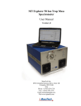
Q-Tof 2
User’s Guide
Micromass UK Limited
Floats Road
Wythenshawe
M23 9LZ
Tel: +44 161 945 4170 Fax: +44 161 998 8915
Tudor Road
Altrincham
WA14 5RZ
Tel: +44 161 282 9666 Fax: +44 161 282 4400
http://www.micromass.co.uk
The instrument is marked with this symbol where high voltages are
present.
The instrument is marked with this symbol where hot surfaces are
present.
The instrument is marked with this symbol where the user should refer to
this User's Guide for instructions which may prevent damage to the
instrument.
Warnings are given throughout this manual where care is required to avoid personal
injury.
If the instrument is used in a manner not specified by the manufacturer, the protection
provided by the equipment may be impaired.
This manual is a companion to the MassLynx NT User's Guide supplied with the
instrument. All information contained in these manuals is believed to be correct at the
time of publication. The publishers and their agents shall not be liable for errors
contained herein nor for incidental or consequential damages in connection with the
furnishing, performance or use of this material. All product specifications, as well as
the information contained in this manual, are subject to change without notice.
Micromass ® is a registered trade mark of Micromass Limited
(Reg. U.S. Pat. & T.M. Off.).
Code: 6666526
Issue 1
© Micromass Ltd.
Table of Contents
Q-Tof 2
User's Guide
Table of Contents
Q-Tof 2
User’s Guide
Contents
Instrument Description
Introduction
Ionisation Techniques
Atmospheric Pressure Chemical Ionisation
Electrospray
Nanoflow Electrospray
Ion Optics
Internal Layout
Mechanical Components
Electronics
The Vacuum System
Fine Pumping
Rotary Pumping
Pressure Measurement
Vacuum Protection
Front Panel Connections
Desolvation Gas and Probe Nebuliser Gas
High Voltage
Heaters
Front Panel Controls and Indicators
Status Display
Flow Control Valves
Divert / Injection Valve
Rear Panel Connections
Water
Nitrogen Gas In
Exhausts
Supply Inlet
Electronics
Rotary Pump
Event Out
Contact Closure In
Analog Channels
MassLynx NT Data System
Software
9
10
10
10
10
11
12
12
14
16
16
16
16
17
18
18
18
18
19
19
19
19
20
20
20
21
21
21
21
22
22
22
23
23
Routine Procedures
Start Up Following a Complete Shutdown
Preparation
Pumping
MCP Detector Conditioning
Instrument Warm-up
Using the Instrument
Start Up Following Overnight Shutdown
Preparation for Electrospray Operation
25
25
26
26
27
27
28
28
Table of Contents
Q-Tof 2
User's Guide
Preparation for APcI Operation
Transient Pressure Trip
Power Failure
Nitrogen Supply
Tuning
Source Tuning Menu
Capillary
Cone
Extractor
RF Lens
Source Block Temp
Desolvation Temp
Analyser Tuning Menu
LM Res and HM Res
Collision
Ion Energy
Steering
Entrance
Multiplier
MCP
MS2 Tuning Menu
Transport
Aperture 2
AccV
Focus
Tube Lens
Offset 1
Offset 2
Pusher
TOF
Reflectron
Prefilter
Manual Pusher
Other Tune Page Settings
TDC Settings
Start
Stop
Threshold
Bunching
Lteff
Centroid
Calibration
Data Acquisition
Data Processing
Shutdown Procedures
Emergency Shutdown
Overnight Shutdown
Complete Shutdown
Table of Contents
29
30
30
31
32
33
33
33
33
33
34
34
34
34
35
35
35
35
35
35
36
36
36
36
36
37
37
37
37
37
37
37
38
39
39
39
39
39
39
40
40
40
40
40
41
41
41
41
Q-Tof 2
User’s Guide
Electrospray
Introduction
Post-column Splitting
Megaflow
Changing Between Flow Modes
Operation
Checking the ESI Probe
Obtaining an Ion Beam
Tuning and Optimisation
Probe Position
Nebuliser Gas
Desolvation Gas
Cone Gas
Purge Gas
Source temperature
Capillary Voltage
Sample Cone Voltage
Extraction Cone Voltage
Megaflow Hints
Removing the Probe
Sample Analysis and Calibration
General Information
Typical ES Positive Ion Samples
Typical ES Negative Ion Samples
Chromatographic Interfacing
LC-MS Sensitivity Enhancement
43
45
46
46
47
47
48
49
49
49
49
50
51
52
52
52
52
53
54
55
55
56
56
57
58
Nanoflow Electrospray
Overview
Installing the Interface
Operation of the Camera System
Using the Microscope
Glass Capillary Option
Installation
Nanovial Tip Position
Operation
Restarting the Spray
Nano-LC Option
Installation
Operation
Changing Options
61
62
65
65
66
66
67
67
67
68
68
69
70
Table of Contents
Q-Tof 2
User's Guide
Atmospheric Pressure Chemical Ionisation
Introduction
Preparation
Checking the Probe
Obtaining an Ion Beam
Hints for Sample Analysis
Tuning
Mobile Phase
Probe Temperature
Desolvation Gas
Removing the Probe
71
73
73
75
77
77
77
77
77
78
Calibration and Accurate Mass
Introduction
Nominal Mass Accuracy
Calibration
Lock Mass
Dead Time Correction
Generation of an Instrument Calibration
Lock Mass Correction
Deadtime Correction
Exact Mass Measurement: Additional Hints
81
81
82
82
83
83
88
89
93
Parent Ion Scanning
Introduction
Unlocking the Parent Scan Facility
Setting up the Mass Transmission of the Quadrupole
Setting up a Scan Function for Precursor Scanning
(i) Multi Step Mode
(ii) Single Step Mode
Multi Step mode
Parent Scan Options
Single Step Mode
Acquiring the Data
Displaying the Data
The Precursor Scan
Constant Neutral Loss or Gain Scans
The Product Scan
The Precursor Scan Multi Step Mode
Table of Contents
95
96
97
98
98
98
98
100
102
103
103
103
105
105
106
Q-Tof 2
User’s Guide
Maintenance and Fault Finding
Introduction
Removal and Replacement of Outer Panels
Electronics Maintenance
Cooling Fans and Air Filters
The Vacuum System
Vacuum Leaks
Pirani Gauge
Active Inverted Magnetron Gauge
Gas Ballasting
Oil Mist Filter
Rotary Pump Oil
Foreliune Trap
The Source
Overview
Cleaning the Sample Cone in Situ
Removing and Cleaning the Sample Cone
Removing and Cleaning the Source Block and Extraction Cone
Removing and Cleaning the RF Lens Assembly
Reassembling and Checking the Source
The Corona Discharge Pin
The Electrospray Probe
Overview
Replacement of the Stainless Steel Sample Capillary
The APcI Probe
Cleaning the Probe Tip
Replacing the Probe Tip Heater
Replacing the Fused Silica Capillary
The Analyser
Removing the MS1 and Collision Cell Optical Bench Assembly
Dismantling and Cleaning the Entrance Prefilter
Cleaning the MS1 Analyser Assembly
Replacing the MS1 and Gas Cell Optical Bench Assembly
The MS2 Analyser and Detector Assembly
Fault Finding
Introduction
No Beam
Unsteady Beam
High Back Pressure
Loss of Sensitivity
Incorrect Isotope Distributions
High Noise Levels
Chemical Noise
Electronic Noise
Poor Analyser Vacuum
Cleaning Materials
Preventive Maintenance Check List
109
110
112
113
113
113
114
114
114
115
115
115
116
116
117
119
121
123
125
126
127
127
129
131
131
132
133
135
136
136
137
137
138
139
139
139
140
141
142
142
143
143
143
143
144
145
Table of Contents
Q-Tof 2
User's Guide
Reference Information
Overview
Positive Ion
Horse Heart Myoglobin
Polyethylene Glycol
PEG + NH4+
Sodium Iodide and Caesium Iodide Mixture
Sodium Iodide and Rubidium Iodide Mixture
Negative Ion
Horse Heart Myoglobin
Mixture of Sugars
Sodium Iodide and Caesium Iodide (or Rubidium Iodide) Mixture
Preparation of Calibration Solutions
PEG + Ammonium Acetate for Positive Ion Electrospray and APcI
PEG + Ammonium Acetate for Positive Ion Electrospray
(Extended Mass Range)
Sodium Iodide Solution for Positive Ion Electrospray
Method 1
Method 2
Sodium Iodide Solution for Negative Ion Electrospray
Table of Contents
147
148
149
149
149
150
150
151
151
151
152
153
153
153
154
154
154
154
Q-Tof 2
User’s Guide
Instrument Description
Introduction
The Q-Tof 2 hybrid quadrupole time of flight mass spectrometer is available with
electrospray ionisation (ESI) and atmospheric pressure chemical ionisation (APcI).
Q-Tof 2 utilises a high performance, research grade quadrupole mass analyser,
incorporating a prefilter assembly to protect the main analyser from contaminating
deposits, and an orthogonal acceleration time of flight (TOF) mass spectrometer. A
hexapole collision cell, between the two mass analysers, can be used to induce
fragmentation to assist in structural investigations.
Ions emerging from the second mass analyser are detected by the microchannel plate
detector and ion counting system. A post acceleration photomultiplier detector
(Dynolite™), situated after the orthogonal acceleration cell, is used to detect the beam
passing through the first stage of the instrument for tuning and optimisation.
A PC computer runs the MassLynx NT software system to control Q-Tof 2, and to
acquire and process data.
Instrument Description
Page 9
Q-Tof 2
User's Guide
Ionisation Techniques
Using the Micromass Z-spray atmospheric pressure ionisation (API) source, two
techniques are available.
Atmospheric Pressure Chemical Ionisation
Atmospheric pressure chemical ionisation (APcI) generally produces protonated or
deprotonated molecular ions from the sample via a proton transfer (positive ions) or
proton abstraction (negative ions) mechanism. The sample is vapourised in a heated
nebuliser before emerging into a plasma consisting of solvent ions formed within the
atmospheric source by a corona discharge. Proton transfer or abstraction then takes
place between the solvent ions and the sample. Eluent flows up to 2 millilitres/minute
can be accommodated without splitting the flow.
Electrospray
Electrospray ionisation (ESI) takes place as a result of imparting a strong electrical
charge to the eluent as it emerges from the nebuliser. An aerosol of charged droplets
emerges from the nebuliser. These undergo a reduction in size by solvent evaporation
until they have attained a sufficient charge density to allow sample ions to be ejected
from the surface of the droplet (“ion evaporation”).
A characteristic of ESI spectra is that ions may be singly or multiply charged. Since
the mass spectrometer filters ions according to their mass-to-charge ratio (!),
compounds of high molecular weight can be determined if multiply charged ions are
formed.
Eluent flows up to 1 ml/min can be accommodated although it is often preferable with
electrospray ionisation to split the flow such that 5-50 µl/min of eluent enters the mass
spectrometer.
Nanoflow Electrospray
The optional nanoflow interface allows electrospray ionisation to be performed in the
flow rate range 5 to 1000 nanolitres per minute.
For a given sample concentration, the ion currents observed in nanoflow are
comparable to those seen in normal flow rate electrospray. Great sensitivity gains are
therefore observed when similar scan parameters are used, due to the great reductions
in sample consumption.
Instrument Description
Page 10
Q-Tof 2
User’s Guide
Ion Optics
Z-spray
Ion Source
Hexapole
Quadrupole
Transfer
Lens
Analyser
RF Lens
Hexapole
Pusher
Collision Cell
Dynolite
Point
Detector
MCP
Detector
Probe
MS1 (Quadrupole MS)
The principal components of the ion optical
system are shown here in schematic form.
Ions generated in the Z-spray source are
transferred to the quadrupole analyser MS1
via the independently pumped RF lens.
After leaving the quadrupole analyser the
ions flow into the orthogonal time of flight
analyser MS2. The ion beam is focused
into the pusher by the acceleration, focus,
steer and tube lenses. The pusher then
pulses a section of the beam towards the
reflectron, which then reflects ions back to
the detector.
Reflectron
MS2 (TOF MS)
As ions travel from the pusher to the detector they are separated in mass according to
their flight times, with ions of the highest mass to charge ratio (!) arriving later.
The pusher may be operated at repetition frequencies of up to 20 kHz, resulting in a
full spectrum being recorded by the detector every 50 microseconds. Each spectrum is
summed in the histogram memory of the time to digital converter until the
histogrammed spectrum is transferred to the host PC.
If the user has requested an acquisition rate of 1 spectrum/second, each spectrum
viewed on the host PC will be the result of summing up to 20,000 individual spectra
recorded at the detector.
Instrument Description
Page 11
Q-Tof 2
User's Guide
Unlike scanning instruments, the TOF performs parallel detection of all masses within
the spectrum at very high sensitivity and acquisition rates. This characteristic is of
particular advantage when the instrument is coupled to fast chromatography, since
each spectrum is representative of the sample composition at that point in time,
irrespective of how rapidly the sample composition is changing.
Internal Layout
Warning: The covers should not be removed without first isolating the
instrument at the electricity supply.
Caution: The internal layout is shown in the following diagrams for information
only, and does not imply that labelled components are user-serviceable.
Mechanical Components
TOF
Analyser
Rotary
Pump
Quadrupole
Analyser
Housing
Embedded
Control Computer
RF Generator
Z-spray
Source
Instrument Description
Page 12
RF Lens 1
Housing
Turbomolecular
Pumps
Q-Tof 2
User’s Guide
The main internal mechanical components of the instrument are:
• The source housing, containing the RF (hexapole) lens.
• The MS1 analyser housing, containing the quadrupole analyser, hexapole
collision cell and hexapole transfer lens
• The TOF analyser housing, containing the pusher, detector and reflectron
assemblies.
• Three 250 litre/second turbomolecular pumps.
• Two active inverted magnetron (Penning) gauges and two Pirani gauges.
Instrument Description
Page 13
Q-Tof 2
User's Guide
Electronics
The main electronics unit is located in the lower section of the instrument behind the
operator control panel. This contains:
• High voltage power supplies.
These supply the probe or corona, Dynolite point detector, reflectron,
TOF flight tube and lens circuits.
• Low voltage power supplies.
These supply the PCBs, high voltage supplies and turbomolecular pumps.
• Main PCBs.
For communications, lenses and quadrupole control.
Power Supplies
PCBs
Instrument Description
Page 14
Q-Tof 2
User’s Guide
The following electronics modules are located adjacent to the TOF analyser housing:
• Pusher unit.
This produces the high frequency pusher voltage, and the MCP voltage.
• TDC preamplifier, attenuator and photomultiplier preamplifier.
These components condition the output of the detector before the signal travels
to the TDC.
TOF Pusher
RF Generator
Photomultiplier Preamplifier
Attenuator
Coaxial Surge Protector
TDC Preamplifier
Instrument Description
Page 15
Q-Tof 2
User's Guide
The Vacuum System
Z-spray
Ion Source
Probe
Active Inverted
Magnetron Gauge
Pirani
Gauge
Quadrupole Analyser
Gas Cell
Speedivalve
Solenoid
Valve
TOF
Analyser
Pirani
Gauge
Turbomolecular
Pumps
CID
Gas
Oil Mist
Filter
Rotary
Pump
Exhaust
Automatic
Vent
(to N2)
Fine Pumping
Q-Tof 2 is equipped with three water cooled turbomolecular pumps, providing
independent fine pumping of the source hexapole, quadrupole and TOF analysers.
Details of the operation and maintenance of the pumps can be found in the
manufacturer’s manuals provided.
Rotary Pumping
Source pumping and turbomolecular pump backing is by a direct drive rotary pump.
The rotary pump is situated at the front of the instrument. Details of the operation and
maintenance of the pump can be found in the manufacturer’s manual provided.
Pressure Measurement
The backing pressure is monitored by an active Pirani gauge. The analyser and TOF
pressures are monitored by active inverted magnetron (Penning) gauges. These gauges
act as vacuum switches, switching the instrument out of Operate mode if the
pressure is too high. Pressure readings may be displayed on the MassLynx NT tune
page.
The analyser Penning gauge only comes on when the vacuum display window is open.
At other times the gauge is off. The analyser Pirani gauge is used when the diaply is
off, though no pressures are shown.
Instrument Description
Page 16
Q-Tof 2
User’s Guide
Vacuum Protection
The vacuum system is fully interlocked to provide adequate protection in the event of:
• a fault in the vacuum system.
• a failure of the power supply.
• a failure of the water supply.
• a vacuum leak.
Instrument Description
Page 17
Q-Tof 2
User's Guide
Front Panel Connections
STANDBY
PUMP
OPERATE
TRIP
CAPILLARY / CORONA
PROBES
NANOFLOW
INJECTOR
LOAD
DESOLVATION GAS
INJECT
NEBULISER GAS
GAS CELL
NANOFLOW
DESOLVATION GAS
GAS
CONE GAS
Desolvation Gas and Probe Nebuliser Gas
The PTFE gas lines for the Desolvation Gas and probe Nebuliser Gas are
connected to the front of the instrument using threaded metal fittings. Cone Gas is
connected internally.
High Voltage
The electrical connection for the ESI capillary or the APcI corona discharge pin is via
the coaxial high voltage connector. This socket is labeled Capillary / Corona.
Heaters
The electrical connection for the APcI probe or the ESI desolvation heater is via the
multi-way connector labeled Probes. This is removed from the front panel by pulling
on the metal sleeve of the plug. Both the electrospray desolvation heater and the APcI
probe heater use this connector.
Instrument Description
Page 18
Q-Tof 2
User’s Guide
The power for the source block heater is permanently connected. As a consequence,
the source block assembly is usually very hot, and should not be touched.
Front Panel Controls and Indicators
Status Display
The display on the front panel of the instrument consists of two 3-colour light emitting
diodes (LEDs).
The display generated by the Pump LED is dependent on the vacuum status of the
instrument. The Operate LED depends on both the vacuum status and whether the
operate mode has been selected from the Data System. Further information is included
in Automatic Pumping and Vacuum Protection (see Routine Procedures).
Flow Control Valves
The Desolvation Gas and Cone Gas needle valves are five-turn valves. The flow
increases as the valve is turned counterclockwise. The Nebuliser Gas valve is a
four-turn valve.
Divert / Injection Valve
The divert / injection valve may be used in several ways depending on the plumbing
arrangement:
• As an injection valve, with the needle port and sample loop fitted.
• As a divert valve, to switch the flow of solvent during a LC run.
• As a switching valve to switch, for example, between a LC system and a syringe
pump containing calibrant.
This valve is pneumatically operated, using the same nitrogen supply as the rest of the
instrument.
The two switches marked Load and Inject enable the user to control the valve when
making loop injections at the instrument.
Instrument Description
Page 19
Q-Tof 2
User's Guide
Rear Panel Connections
Collision Gas In
Nitrogen In
Nitrogen Out
Water In
Water Out
Exhaust
Water
Water is used to cool the turbomolecular pumps.
Nitrogen Gas In
The nitrogen supply (100 psi, 7 bar) should be connected to the Nitrogen Gas In
push-in connector using 6mm PTFE tubing. If necessary this tubing can be connected
to ! inch tubing using standard ! inch fittings.
Caution: Use only PTFE tubing or clean metal tubing to connect between the
nitrogen supply and the instrument. The use of other types of plastic tubing will
result in chemical contamination of the source.
Instrument Description
Page 20
Q-Tof 2
User’s Guide
Exhausts
The exhaust from the rotary pump should be vented to atmosphere outside the
laboratory.
The gas exhaust, which also contains solvent vapours, should be vented via a separate
fume hood, industrial vent or cold trap.
The gas exhaust should be connected using 10mm plastic tubing connected to the
push-in fitting.
Caution: Do not connect these two exhaust lines together as, in the event of an
instrument failure, rotary pump exhaust could be admitted into the source
chamber producing severe contamination.
Supply Inlet
The mains power cord should be wired to a 230V mains outlet using a suitable plug,
or to a transformer. For plugs with an integral fuse, the fuse should be rated at
13 amps (UK only).
Electronics
This circuit breaker switches power to the electronics. In the event of the instrument
drawing more than the rated current, the circuit breaker will trip.
Rotary Pump
This circuit breaker switches power to the rotary and turbomolecular pumps. In the
event of the pumps drawing more than the rated current, it will trip.
Instrument Description
Page 21
Q-Tof 2
User's Guide
Event Out
Four outputs, Out 1 to Out 4, are provided to allow various peripherals to be
connected to the instrument. Switches S1 to S4 allow each output to be set to be
either a contact closure (upper position) or a voltage output (lower position).
Out 1 and Out 2, when set to voltage output, each have an output of 5 volts. The
voltage output of both Out 3 and Out 4 is 24 volts.
During a sample run an event output may be configured to close between acquisitions
and is used typically to enable an external device to inject the next sample.
Contact Closure In
In 1 and In 2 inputs are provided to allow an external device to start sample
acquisition once the device has performed its function (typically sample injection).
Analog Channels
Four analog channel inputs are available, for acquiring simultaneous data such as a
UV detector output. The input differential voltage must not exceed one volt.
Instrument Description
Page 22
Q-Tof 2
User’s Guide
MassLynx NT Data System
A PC computer runs the MassLynx NT software system to control Q-Tof 2, and to
acquire and manipulate data from it. A high resolution colour monitor is also supplied.
Interaction with MassLynx NT is via the mouse and keyboard using menu-driven
commands. Printing, file management and other routine procedures are performed
using the appropriate Windows NT modules.
Software
The following software packages are supplied with Q-Tof 2:
• MassLynx NT
• Screen Capture, a utility for copying user selected areas of any Windows
display. The selected area can be printed directly, or saved as a bitmap file for
importing into other Windows NT applications.
• DataBridge, a utility to convert other format data files into MassLynx format.
• Microsoft Windows NT graphical environment.
• Mouse configuration.
A range of optional software modules for different applications is also available.
The MassLynx NT User’s Guide describes the many facilities of the Micromass
software. Documentation for the other software is also supplied.
Instrument Description
Page 23
Q-Tof 2
User's Guide
Instrument Description
Page 24
Q-Tof 2
User’s Guide
Routine Procedures
Start Up Following a Complete Shutdown
Preparation
If the instrument has been unused for a lengthy period of time, proceed as follows:
Check the level of oil in the rotary pump sight glass. Refill or replenish as
necessary as described in the pump manufacturer’s literature.
Connect a supply of dry, high purity nitrogen to the connector on the service
panel at the rear of the instrument. Adjust the outlet pressure to 7 bar (100 psi).
Connect the water supply to the connections at the rear of the instrument.
Check that the rotary pump exhaust is connected to a suitable vent.
Check that the exhaust gas from the instrument is connected to a suitable vent.
Caution: Do not connect the two exhaust lines together. In the event of an
instrument failure, rotary pump exhaust could be admitted into the source
chamber, producing severe contamination.
Check that the instrument, data system and other peripheral devices (LC
equipment, printer etc.) are connected to suitable mains supplies.
Check that the etherlink connection is made between the control PC and the
embedded PC.
Ensure that the VxWorks disk is inserted into the drive of the embedded PC.
Switch on the host PC. Log on to Windows NT and wait for the system to boot
up before the Q-Tof 2 is switched on.
Switch on the mains to the mass spectrometer using the two circuit breakers
situated on the service panel at the rear of the instrument.
Log on to Micromass account (password analysis).
Windows NT and MassLynx NT are configured to prevent unauthorised access.
On the host PC, double-click on the MassLynx icon in the Windows desktop and
display the tune page.
Routine Procedures
Page 25
Q-Tof 2
User's Guide
Pumping
Caution: To minimise wear to the lubricated components of the rotary pump, the
manufacturers recommend that the pump is not started when the oil temperature
is below 12°C.
Select Vacuum from the menu bar at the top of the tune page.
Click on Pump.
The rotary pump and the turbomolecular pumps start simultaneously.
The Vacuum LED on the front of the instrument shows amber as the system
pumps down.
When the system has reached operating vacuum the Vacuum LED changes to a
steady green.
If the rotary pump oil has been changed or replenished, open the gas ballast
valve on the rotary pump. See the pump manufacturer's literature for details.
Rotary pumps are normally noticeably louder when running under gas ballast.
If opened, close the gas ballast valve when the rotary pump has run under gas
ballast for 30 minutes.
MCP Detector Conditioning
The MCP detector must be conditioned before
use, by gradually increasing the applied
voltage over a long time period. This is
necessary to allow escape of all absorbed
water from within the microchannels.
Under normal operation the analyser
automatically vents to dry nitrogen. However,
if the nitrogen supply was not connected to the
instrument when last vented, or if the
instrument has been left vented for more than
one day, a significant amount of water vapour
may have entered the analyser. Under these circumstances it is good practice to allow
the instrument to pump for 12 hours before commencing the conditioning process.
In all cases, the TOF pressure must be 1e-6 mbar prior to commencing MCP
conditioning.
MCP conditioning should be repeated after every instrument venting.
It is not necessary to recondition the detector if the instrument has been left out
of the operate mode while still under vacuum.
Routine Procedures
Page 26
Q-Tof 2
User’s Guide
During routine cleaning of the source sample cone, the source isolation valve is
closed in order to maintain analyser vacuum. It is not, therefore, necessary to
recondition the detector after this procedure.
The procedure for MCP conditioning is as follows:
Ensure that the analyser pressure is 1e-6 mbar.
Check that the MCP Detector voltage is set to zero on the tune page.
Switch the instrument into Operate.
Select Other, MCP Conditioning to access the MCP conditioning program.
Set Start to 100V, Stop to 2400V, Duration to 600 minutes and Step to
5 minutes.
A ‘quick condition’ may be performed following brief venting, after source
cleaning for example.
Set Start to 100V, Stop to 2400V, Duration to 120 minutes and Step to
1 minute.
Caution: Failure to follow the recommended MCP conditioning procedure can
severely reduce detector lifetime.
Instrument Warm-up
Switch the instrument into the operate mode by selecting Operate on the
MassLynx tune page.
For the best mass accuracy to be obtained the instrument temperature must be
stabilised for a minimum of two hours after switching into operate.
Leaving the instrument continuously in operate does not shorten the detector
lifetime. It is recommended that the instrument is left in operate at all times
(except of course during maintenance procedures) in order to reduce mass scale
drifts due to temperature changes. Switching the instrument out of operate mode
overnight is not necessary.
Using the Instrument
The Q-Tof 2 is now almost ready to use. To complete the start up procedure and
prepare for running samples, follow the instructions in Start Up Following Overnight
Shutdown in the following pages.
Routine Procedures
Page 27
Q-Tof 2
User's Guide
Start Up Following Overnight Shutdown
The instrument will have been left in the operate mode under vacuum.
It is recommended that the data system is left on overnight. However, if the data
system has been switched off, switch it on as described in the preceding section.
Preparation for Electrospray Operation
If the corona discharge pin is fitted, proceed as follows:
Deselect Operate from the tune page to put the instrument into standby mode.
Disconnect the gas and electrical connections from the front panel.
Unscrew the probe thumb nuts and remove the probe.
Undo the three thumb screws and remove the probe adjustment flange and glass
tube.
Warning: The ion source block can be heated to temperatures of 150°C, and
will be maintained at the set temperature when the source enclosure is removed.
Touching the ion block when hot may cause burns to the operator.
Disconnect the APcI high voltage cable from the socket positioned at the bottom
right corner of the source flange.
Remove the corona discharge pin from its mounting contact, and fit the blanking
plug.
Replace the glass tube and adjustment flange.
Ensure that the source enclosure is in place.
The Z-spray source enclosure consists of the glass tube and the probe
adjustment flange.
Warning: Operating the source without the source enclosure will
result in solvent vapour escape and the exposure of hot surfaces and
high voltages.
With the corona discharge pin removed, the plug fitted and the source enclosure in
place, proceed as follows:
Connect the source’s gas line to Desolvation Gas on the front panel. Tighten
the nut to ensure a good seal.
Check that the lead of the probe adjustment flange is plugged into the socket
labelled Probes on the front panel.
Connect the electrospray probe's gas line to Nebuliser Gas on the front panel.
Routine Procedures
Page 28
Q-Tof 2
User’s Guide
Connect the liquid flow of a LC system or syringe pump to the probe.
Insert the probe into the source and tighten the two thumb nuts to secure the
probe firmly.
Plug the probe lead into Capillary / Corona on the front panel.
If necessary, change the ionisation mode using the Ion Mode command.
Set Source Block Temp to 100°C and Desolvation Temp to 120°C.
Caution: The maximum operating temperature for the source heater is 150°C.
Do not set Source Block Temp higher than 150°C.
Preparation for APcI Operation
If the corona discharge pin is not fitted, proceed as follows:
Deselect Operate from the tune page to put the instrument into standby mode.
Disconnect the gas and electrical connections from the front panel.
Unscrew the probe thumb nuts and remove the probe.
After a period of operation at high flow rates, allow the glass source enclosure to
cool before removal.
Undo the three thumb screws and remove the probe adjustment flange and glass
tube.
Warning: The ion source block can be heated to temperatures of 150°C, and
will be maintained at the set temperature when the source enclosure is removed.
Touching the ion block when hot may cause burns to the operator.
Remove the blanking plug from the discharge pin mounting contact and fit the
corona discharge pin, ensuring that the tip is in line with the tip of the sample
cone.
Connect the APcI high voltage cable between Capillary / Corona and the
socket positioned at the bottom left corner of the source flange.
Replace the glass tube, adjustment flange and moulded cover.
Warning: Operating the source without the source enclosure will
result in solvent vapour escape and the exposure of hot surfaces and
high voltages.
With the corona discharge pin fitted and the source enclosure in place, proceed as
follows:
Insert the APcI probe into the source and tighten up the two thumb screws.
Routine Procedures
Page 29
Q-Tof 2
User's Guide
If necessary, change the ionisation mode using the Ion Mode command.
Set Source Temp to 150°C.
Caution: The maximum operating temperature for the source heater is 150°C.
Do not set Source Temp higher than 150°C.
Do not start the liquid flow until the gas flow and probe heater are switched on
with the probe inserted.
Transient Pressure Trip
The transient trip is designed to protect the instrument from potentially damaging
pressure surges and operates routinely whenever the pressure rises.
Should the vacuum gauge(s) detect a pressure surge above the preset trip level
(normally set at 1e-5 mbar by software) the following events occur:
• The green Pump lamp becomes amber.
• If in the operate mode, the system turns off the critical source, analyser and
detector voltages, and the green Operate lamp becomes amber.
• Acquisition continues though, of course, no real data are recorded.
When the vacuum recovers:
• The amber Pump lamp becomes green.
• If previously in the operate mode, voltages are restored and Operate reverts to
green.
The period during which the trip was operative will appear in a raw total ion
chromatogram as a period of reduced baseline noise.
Further deterioration of the system pressures results in a “vacuum fault” condition and
the system is shut down (see below).
Power Failure
In the event of an unexpected failure of the electrical supply the instrument is vented
safely. If power is unlikely to be restored quickly, follow the shutdown procedure
described later in this chapter. When power is restored follow the startup procedure.
Should the power fail and then be restored while the instrument is unattended, the
system will continue to vent, and will require to be pumped down in accordance with
the start-up procedure.
Routine Procedures
Page 30
Q-Tof 2
User’s Guide
Nitrogen Supply
Replacement of nitrogen cylinders should be conducted in accordance with the
operation, handling and storage instructions provided by the local gas supplier.
Toggle the API gas button to Off, to close the nitrogen inlet valve prior to
disconnecting the supply.
Set the nitrogen inlet pressure to 7 bar (100 psi).
Under no circumstances should the nitrogen pressure exceed 10 bar (140 psi).
Routine Procedures
Page 31
Q-Tof 2
User's Guide
Tuning
The preceding sections have outlined the software controls and connections to
establish the physical conditions required as a prerequisite to mass spectrometer
operation.
Within the source and analyser enclosures, electric fields controlled via MassLynx are
applied to the components to manage the ion beam generated, according to the sample
to be analysed, the ionisation mode and the type of information required. The ion
optical system elements are indicated in the following schematic diagram.
10
13
11 12
3
9
8
14
2
15
4
5
1
7
16
6
20
6
1
Sample Cone
2
Extraction Cone
3
RF Hexapole
4
Pre-filter
5
Post-filter
6
Differential Pumping Aperture
7
Transport RF Hexapole
14
Phosphor
8
Analyser Quadrupole
15
Anode
9
Gas Cell RF Hexapole
16
MCP
10
Acceleration Lens
17
Conversion Dynode
11
Steering/Focus Lens
18
Flight Tube
12
Tof Entry
19
Reflectron
13
Photomultiplier
20
Tube
17
18
19
Considering the variable nature of the beam with different samples, the instrument
should be tuned for signal strength and calibrated for accurate ! using suitable
reference compounds, prior to the acquisition of sample data.
Tuning parameters have been grouped in MassLynx into 3 menus as described below.
Full details of source tuning procedures for electrospray, APcI and nanoflow
electrospray are given in the relevant chapter of this document.
Routine Procedures
Page 32
Q-Tof 2
User’s Guide
Source Tuning Menu
The positive ion electrospray (ESP+) source tuning menu is shown. Suggested tuning
parameters are as follows:
Capillary
This sets the absolute voltage on the electrospray probe or APCI corona needle, and is
typically adjusted to 3000V.
Cone
This sets the voltage on the sampling cone relative to the extraction lens. It is
dependent on compound and charge state. For multiply charged species this is set to
40 - 50eV, and higher for singly charged species. In general, higher cone voltages are
needed for larger mass ions.
Extractor
This sets the voltage on the extraction lens, and is normally set from 0 - 2V.
RF Lens
This sets the offset voltage on the hexapole and the first differential pumping aperture.
It is usually set to 1V.
Routine Procedures
Page 33
Q-Tof 2
User's Guide
Source Block Temp
The source block temperature is usually set to 80ºC, but is increased for higher solvent
flow rates.
Desolvation Temp
This sets the temperature of the desolvation gas heater. It is usually set to 150ºC, and
increased for higher solvent flow rates.
Analyser Tuning Menu
LM Res and HM Res
These set the resolving DC on the quadrupoles. The two sliders are set to give
constant resolution across the mass range. When the quadrupoles have been set up,
settings of 15 on both sliders should give unit resolution at 20% peak height.
Routine Procedures
Page 34
Q-Tof 2
User’s Guide
Collision
This sets the collision energy of the ions when they reach the collision cell. The cell
itself is grounded but the collision energy voltage is simultaneously applied to all the
optical elements preceding it. i.e cone, extraction lens, source hexapole, differential
pumping aperture, and quadrupole. In Q-Tof 2 gas is always introduced into the cell,
affording collisional cooling and consequently higher resolution. The collision energy
is set to 10eV for MS mode to maximise ion transmission but produce little or no
fragmentation. When in the MS/MS mode the collision energy is adjusted to give the
best fragmentation pattern for the selected parent.
Ion Energy
This sets the quadrupole offset DC with respect to the collision energy of the ions
travelling between the quadrupoles. This should be set between 1 - 1.8V.
Steering
This adjusts the voltage difference between the top and bottom half plates of the
steering/focus lens. It acts as a y-deflector, directing the beam into the pusher. A
setting close to zero should produce an optimum beam. Better sensitivity can be
achieved, however, with a voltage (positive or negative) close to zero, e.g. +1.0, -0.5
etc., and not more than ±2V.
Entrance
This sets the voltage on the pusher entrance and exit, and defines the axial speed of
the ions through the TOF. The theoretical value is 65eV when the ion beam should be
central to the detector. It should be optimised when looking at a TOF beam, not on the
first detector. It should be possible to correctly tune the instrument using this value.
Multiplier
This sets the photomultiplier voltage, and should typically be set to 550V.
MCP
This sets the voltage on the TOF detector. The voltage across the MCP itself is limited
to 270V less than this value. MCP must be conditioned before applying high voltage.
The TOF analyser is usually operated with this detector set at 2200V.
Routine Procedures
Page 35
Q-Tof 2
User's Guide
MS2 Tuning Menu
Transport
This sets the offset DC on the transport hexapole, and the DC on the apertures of the
gas cell. The optimum setting is usually between 2 - 4V.
Aperture 2
Operating Aperture 2 at 5V generally gives best resolution, but at some cost to
sensitivity. For maximum sensitivity it should be set to around 15V.
AccV
Usually set to maximum voltage (200V) in all modes of operation.
Focus
This adds an equal voltage to both the top and bottom steering/focus lens halfplates.
The optimum setting for the first detector is typically 80 - 130V, but for maximum
TOF resolution it is set to zero.
Routine Procedures
Page 36
Q-Tof 2
User’s Guide
Tube Lens
This is set to its optimum value in the factory and by the engineer at installation. It
helps shape the ion beam on entry into the pusher and so has a large effect on
resolution and peak shape.
The factory setting should be noted, before attempting to improve resolution by
changing its voltage.
Offset 1
This determines the voltage difference between the two plates of the first acceleration
region of the Tof (Pusher and Grid3). It is used as a fine tuning control to optimise
resolution.
The optimum value for this element may change with pusher frequency. The pusher
frequency is dependent on mass range when in automatic pusher mode and takes one
of six discrete values. See pusher rates on Page 38.
Offset 2
This determines the voltage difference between the two plates of the second
acceleration region of the Tof (G3 and puller). It is normally set around zero volts and
does not need to be adjusted.
Pusher
This sets the amplitude of the pusher pulse and is normally set to 980V.
TOF
This sets the flight tube voltage. It is always set to 9.1kV. Adjusting this will change
the peak position and resolution.
Reflectron
This is set expressed as a percentage of the flight tube voltage and its value is 2150V
or about 36.0%. Adjusting this will change the peak position and resolution.
Prefilter
This sets the offset voltage on the quadrupole pre and post filters. The optimum beam
is usually obtained at a setting of 5 - 7V.
It is recommended that a record of these values is kept for future reference.
Routine Procedures
Page 37
Q-Tof 2
User's Guide
Manual Pusher
If the Manual Pusher box is selected from the Other sub-menu then the repetition
frequency of the pusher pulse is determined by the Time entered.
Time may be set between 30 µsec and 255 µsec. Setting Time at less than 30 µsec
defaults to 30 µsec. Entering 0 µsec switches the pusher off.
Increasing the flight time reduces the duty cycle (sampling efficiency) of the TOF
analyser resulting in decreased sensitivity.
For the best mass accuracy the instrument should be re-calibrated if the flight time is
changed.
If Manual Pusher is not selected then the repetition frequency of the pusher pulse is
determined automatically according to the highest ! requested in the acquisition
range, as shown in the table below.
Maximum Flight Time
Routine Procedures
Page 38
44 µsec
Highest !
!1000
62 µsec
1001 - 2000
88 µsec
2001 - 4000
124 µsec
4001 - 8000
176 µsec
8001 - 16000
246 µsec
16001 - 32000
Q-Tof 2
User’s Guide
Other Tune Page Settings
TDC Settings
To access the TDC (time to digital converter) settings:
Select Other, TDC settings.
Start
This is the size of the trigger signal that is necessary to trigger the TDC (start the
clock). The start signal is derived from the pusher voltage itself, and a typical value is
800mV. This voltage may be different in negative ion mode.
Stop
This is the size of pulse needed to register as being an ion, so stopping the clock. It is
usually set at 100mV, a value high enough to prevent electronic noise being detected
as ions.
Threshold
This parameter should normally be set to zero. Setting to 1 will cause all peaks in the
spectrum with one count to be thresholded out.
Bunching
This facility can reduce data file size, although at the expense of resolution. For most
analyses it is generally set to 1.
Routine Procedures
Page 39
Q-Tof 2
User's Guide
Lteff
This is used to make the TOF mass measurement nominally correct without a
calibration. The default value is 1800.
To adjust the nominal mass scale (as displayed on the tune page without calibration):
Acquire a TOF spectrum of a standard compound with Lteff set to 1800.
Calculate the new value of Lteff from the relation:
Lteff = 1800 (mind) ÷ (mact)
where:
mind = indicated !.
mact = actual !.
Enter the new Lteff value in the tune page.
Once the new Lteff value has been entered all subsequent acquisitions should
nominally be correctly mass measured.
Centroid
If data is acquired in centroid format, the right-hand section of the dialog displays the
settings generated during the instrument calibration, described in Calibration and
Accurate Mass later in this document. This feature was introduced with MassLynx
Version 2.0 and is absent from previous versions of MassLynx.
Calibration
Information concerning the calibration of Q-Tof 2 is provided in Calibration and
Accurate Mass later in this document and in the Guide to Data Acquisition.
Data Acquisition
The mechanics of the acquisition of sample data are comprehensively described in the
Guide to Data Acquisition. Refer to that publication for full details.
Data Processing
The processing of sample data is comprehensively described in the
MassLynx NT User’s Guide. Refer to that publication for full details.
Routine Procedures
Page 40
Q-Tof 2
User’s Guide
Shutdown Procedures
Emergency Shutdown
In the event of having to shut down the instrument in an emergency, proceed as
follows:
Switch off the power at the wall mounted isolation switch(es), if fitted. If not,
switch the power off at the rear of the instrument and switch off all peripherals.
A loss of data is likely.
Disconnect any LC systems to prevent solvent flowing into the source.
Overnight Shutdown
When the instrument is to be left unattended for any length of time, for example
overnight or at weekends, proceed as follows:
Switch off the LC pumps.
Set Capillary to 0V.
Undo the finger-tight connector on the probe to release the tubing leading from
the LC system.
Before disconnecting the probe, it is good practice to temporarily remove the
probe and flush it of any salts, buffers or acids.
If APcI is being used, reduce APcI Probe Temp to ambient temperature.
Caution: Leaving the APcI probe hot with no gas or liquid flow will shorten the
lifetime of the probe heater.
Deselect API Gas to turn off the supply of nitrogen gas.
If the instrument is not to be used for a long period of time:
Reduce Source Block Temp to 60°C.
It is not necessary to turn the instrument out of the operate mode.
Complete Shutdown
If a power cut is expected, or if the instrument is to be moved, proceed as follows:
Switch off the LC pumps.
On the tune page, deselect Operate to put the instrument in standby mode.
Routine Procedures
Page 41
Q-Tof 2
User's Guide
The tune page indicator changes to red, indicating that the instrument is no
longer in the operate mode.
Undo the finger-tight connector on the probe to release the tubing leading from
the LC system.
Before disconnecting the probe, it is good practice to temporarily remove the
probe and flush it of any salts, buffers or acids.
If APcI is being used, reduce APcI Probe Temp to ambient temperature.
Caution: Leaving the APcI probe hot with no gas or liquid flow will shorten the
lifetime of the probe heater.
Deselect API Gas to turn off the supply of nitrogen gas.
Select Other from the menu bar at the top of the tune page. Click on Vent.
The turbomolecular pumps switch off.
When the turbomolecular pumps have run down to 80% of their normal
operating speed the vent valve opens and the instrument is automatically vented
to dry nitrogen.
The rotary pump switches off.
Exit MassLynx.
Shut down the host PC.
Switch off all peripherals.
Switch off the power to the instrument using the circuit beakers on the rear
panel of the instrument.
Switch off power at the wall mounted isolation switch, or remove the plug.
If the instrument is to be switched off for more than one week:
Drain the oil from the rotary pump according to the manufacturer's instructions.
Refill the rotary pump with new oil.
Routine Procedures
Page 42
Q-Tof 2
User’s Guide
Electrospray
Introduction
Purge Gas
Exhaust
Exhaust
Liner
Probe
Sample
Cleanable
Baffle
Sample
Cone
Nebuliser
Gas
Cone Gas
RF
Lens
Isolation
Valve
Desolvation
Gas
Extraction
Cone
Analyser
Source
Enclosure
Rotary Pump
Turbomolecular
Pumps
The ESI interface consists of the standard Z-spray source fitted with an electrospray
probe. See the following chapter for additional information concerning the optional
nanoflow interface.
Mobile phase from the LC column or infusion pump enters through the probe and is
pneumatically converted to an electrostatically charged aerosol spray. The solvent is
evaporated from the spray by means of the desolvation heater. The resulting analyte
and solvent ions are then drawn through the sample cone aperture into the ion block,
from where they are then extracted into the analyser.
The electrospray ionisation technique allows rapid, accurate and sensitive analysis of a
wide range of analytes from low molecular weight (less than 200 Da) polar
compounds to biopolymers larger than 100 kDa.
Generally, compounds of less than 1000 Da produce singly charged protonated
molecules ([M+H]+) in positive ion mode. Likewise, these low molecular weight
analytes yield ([M-H]–) ions in negative ion mode, although this is dependent upon
compound structure.
High mass biopolymers, for example peptides, proteins and oligonucleotides, produce
a series of multiply charged ions. The acquired data can be transformed by the data
system to give a molecular weight profile of the biopolymer.
Electrospray
Page 43
Q-Tof 2
User's Guide
The source can be tuned to fragment ions within the ion block. This can provide
valuable structural information for low molecular weight analytes.
The most common methods of delivering sample to the electrospray source are:
• Syringe pump and injection valve.
A flow of mobile phase solvent passes through an injection valve to the
electrospray source. This is continuous until the pump syringes empty and need
to be refilled. Sample is introduced through the valve injection loop (usually 10
or 20µl capacity) switching the sample plug into the mobile phase flow. Tuning
and acquisition are carried out as the sample plug enters the source. (At a flow
rate of 10 µl/min a 20µl injection lasts 2 minutes.)
• Reciprocating pump and injection valve.
A flow of mobile phase solvent passes through an injection valve to the
electrospray source. Sample injection and analysis procedure is the same as for
the syringe pump. The pump reservoirs are simply topped up for continuous
operation. The most suitable reciprocating pumps for this purpose are those
which are specified to deliver a flow between 1 µl/min and 1 ml/min. A constant
flow at such rates is more important than the actual flow rate. The injection
valve on reciprocating pumps may be replaced by an autosampler for
unattended, overnight operation.
• Infusion pump.
The pump syringe is filled with sample in solution. The infusion pump then
delivers the contents of the syringe to the source at a constant flow rate. This
arrangement allows optimisation and analysis while the sample flows to the
source at typically 5-30 µl/min. Further samples require the syringe to be
removed, washed, refilled with the next sample, and replumbed.
A 50:50 mixture of acetonitrile and water is a suitable mobile phase for the syringe
pump system and the reciprocating pump systems. This is appropriate for positive and
negative ion operation.
Positive ion operation may be enhanced by 0.1 to 1% formic acid in the sample
solution.
Negative ion operation may be enhanced by 0.1 to 1% ammonia in the sample
solution. Acid should not be added in this mode.
These additives should not be used in the mobile phase for flow injection analysis
(FIA) studies, to allow easy change over between positive and negative ion analysis.
Degassed solvents are recommended for the syringe and reciprocating pumps.
Degassing can be achieved by sonification or helium sparging. The solvents should be
filtered, and stored under cover at all times.
Electrospray
Page 44
Q-Tof 2
User’s Guide
It is wise periodically to check the flow rate from the solvent delivery system. This
can be carried out by filling a syringe barrel or a graduated glass capillary with the
liquid emerging from the probe tip and timing a known volume, say 10µl. Once the
rate has been measured and set, a note should be made of the back pressure readout on
the pump as fluctuation of this reading can indicate problems with the solvent flow.
Post-column Splitting
Although the electrospray source can accommodate flow rates up to 1 ml/min, it is
recommended that the flow is split post-column to approximately 200 µl/min. Also,
even at lower flow rates, a split may be required to save valuable samples.
The post-column split consists of a zero dead-volume tee piece connected as shown.
LC
Column
To Waste
or
UV Cell
The split ratio is adjusted by increasing or decreasing the back pressure created in the
waste line, by changing either the length or the diameter of the waste tube. A UV cell
may also be incorporated in the waste line, avoiding the requirement for in-line, low
volume “Z cells”. As the back pressure is varied, the flow rate at the probe tip should
be checked as described above.
These principles apply to splitting for both megaflow and normal flow electrospray.
Electrospray
Page 45
Q-Tof 2
User's Guide
Megaflow
Megaflow electrospray enables flow rates from 200 µl/min to 1 ml/min to be
accommodated. This allows microbore (2.1mm) or 4.6mm diameter columns to be
interfaced without splitting.
Changing Between Flow Modes
When changing between megaflow and standard electrospray operation, it is essential
that the correct tubing is used to connect the probe to the sample injector. For
megaflow operation 1/16" o.d., 0.007" i.d. peek tubing, easily identified by its yellow
stripe, is used. This replaces the standard fused silica tube, together with the PTFE
sleeves.
Normal Flow Electrospray
PTFE Sleeve
Fused Silica Tube
Probe
Injector
Megaflow Electrospray
1/16" o.d. 0.007" i.d. Peek Tube
Electrospray
Page 46
PTFE Sleeve
Q-Tof 2
User’s Guide
Operation
Exhaust
Liner
Blanking
Plug
Corona
Discharge
Pin
Mounting
Contact
Cleanable
Baffle
High Voltage
Socket
Warning: The probe tip is sharp, and may be contaminated with
harmful and toxic substances. Always take great care when handling
the electrospray probe.
Ensure that the source is assembled as described in Maintenance and Fault
Finding, and that the instrument is pumped down and prepared for electrospray
operation as described in Routine Procedures.
Ensure that a supply of nitrogen has been connected to the gas inlet at the rear of
the instrument and that the head pressure is between 6 and 7 bar (90-100 psi).
Ensure that the exhaust liner and the cleanable baffle are fitted to the source.
This is important for optimum electrospray intensity and stability when
operating at low flow rates.
Checking the ESI Probe
Connect the electrospray probe to a pulse free pump.
Solvent should be degassed to prevent beam instabilities caused by bubbles.
Connect the PTFE tubing of the electrospray probe to Nebuliser Gas on the
front panel. Secure with the nut provided.
Electrospray
Page 47
Q-Tof 2
User's Guide
With the probe removed from the source, turn on the liquid flow at 10 µl/min
and check that liquid flow is observed at the tip of the capillary.
To avoid unwanted capillary action effects, do not allow liquid to flow to the
probe for long periods without the nitrogen switched on.
Turn on Nitrogen by selecting API Gas, and check that a nebuliser flow of
less than 100 litres/hour is registered.
Check that there is gas flow at the probe tip and ensure that there is no
significant leakage of nitrogen elsewhere.
Adjust the probe tip to ensure complete nebulisation of the liquid.
There should be approximately 0.5mm of
sample capillary protruding from the
nebulising capillary.
The tip of the electrospray probe can influence
the intensity and stability of the ion beam. A
damaged or incorrectly adjusted probe tip will
lead to poor electrospray performance.
Using a magnifying glass ensure that both
inner and outer stainless steel capillaries are
straight and circular in cross-section.
0.6mm
Sample
Capillary
Nebulising
Capillary
Probe Tip
Assembly
Ensure that the inner stainless steel capillary is
coaxial to the outer capillary.
If the two capillaries are not coaxial, it is
possible to bend the outer capillary slightly
using thumbnail pressure.
Insert the probe into the source and tighten the two thumb screws.
Plug the probe high voltage cable into Capillary / Corona on the front panel.
Obtaining an Ion Beam
If necessary, change the ionisation mode using the Ion Mode command.
Using the needle valves on the front panel, set the Desolvation Gas flow rate
to 300 litres/hour and the Cone Gas flow to 50 litres/hour.
Turn on the liquid flow at 10 µl/min and set Desolvation Temp to 150°C.
Electrospray
Page 48
Q-Tof 2
User’s Guide
Tuning and Optimisation
The following parameters, after initial tuning, should be optimised using a sample
representative of the analyte to be studied. It will usually be found, with the exception
of the sample cone voltage, that settings will vary little from one analyte to another.
Probe Position
The position of the probe is adjusted
using the probe adjustment collar
(in and out) and the adjustment knob
(sideways) located to the left of the
probe. The two screws can be
adjusted singly or simultaneously to
optimise the beam. The position for
optimum sensitivity and stability for
low flow rate work (10 µl/min) is
shown.
In / Out
Probe
Adjustment
4mm
Cone Gas
Nozzle
8mm
Sideways
Probe
Adjustment
Probe
Tip
Small improvements may be gained by
varying the position using the sample and
solvent system under investigation. The following information should be considered
when setting the probe position:
• 10mm of movement is provided in each direction, with 1.25mm of travel per
revolution of the probe positioning controls.
• At higher liquid flow rates the probe tip should be positioned further away from
the sample cone to achieve optimum stability and sensitivity. The position is less
critical than at lower flow rates.
Nebuliser Gas
Optimum nebulisation for electrospray performance is achieved with a nitrogen flow
between 10 and 20 litres per hour. This can be achieved by fully opening the
Nebuliser Gas flow control valve, which is situated on the instrument’s front panel.
Desolvation Gas
The desolvation gas, also nitrogen, is heated and delivered as a coaxial sheath to the
nebulised liquid spray by the desolvation nozzle.
Electrospray
Page 49
Q-Tof 2
User's Guide
The position of the desolvation nozzle heater is fixed relative to the probe tip
and requires no adjustment.
The Desolvation Gas flow rate is adjusted by the control value situated on the
instrument’s front panel. The optimum Desolvation Temp and flow rate is
dependent on mobile phase composition and flow rate. A guide to suitable settings is
given below.
The Desolvation Gas flow rate indicated on the flow meter represents total
drying flow, that is desolvation gas + cone gas (nanoflow only) + purge gas (if
enabled).
Solvent Flow Rate
µl/min
Desolvation Temp
°C
Desolvation Gas Flow
Rate
litres/hour
<10
100 to 120
200 to 250
10 to 20
120 to 250
200 to 400
20 to 50
250 to 350
200 to 400
>50
350 to 400
500 - 750
Higher desolvation temperatures give increased sensitivity. However increasing the
temperature above the range suggested reduces beam stability. Increasing the gas flow
rate higher than the quoted values leads to unnecessarily high nitrogen consumption.
Caution: Do not operate the desolvation heater for long periods of time without
a gas flow. To do so could damage the source.
Cone Gas
The cone gas reduces the intensity of
solvent cluster ions and solvent adduct ions.
The cone gas flow rate should be optimised
by increasing until solvent cluster ions and
/ or adduct ions are reduced as much as
possible without diminishing the intensity
of the ion of interest, normally (M+H)+.
Cone
Gas
Typical cone gas flow rates are in the range
100 to 300 litres per hour.
Purge Gas
Outlet (Plugged)
Electrospray
Page 50
Q-Tof 2
User’s Guide
Purge Gas
The purge gas is not necessary for most ESI applications. It may be useful for
megaflow operation where an analyte is susceptible to acetonitrile adducting.
Purge gas is enabled simply by removing the blanking plug from the outlet situated
within the source enclosure.
Purge gas flow rate is a constant fraction (30%) of the total desolvation gas flow.
Electrospray
Page 51
Q-Tof 2
User's Guide
Source temperature
100°C is typical for 50:50 CH3CN:H2O at solvent flow rates up to 50 µl/min. Higher
source temperatures, up to 150°C, are necessary for solvents at higher flow rates and
higher water content.
Caution: The maximum operating temperature for the source heater is 150°C.
Do not set Source Temp higher than 150°C.
Capillary Voltage
Capillary usually optimises at 3.0kV, although some samples may tune at values
above or below this, within the range 2.5 - 4.0kV for positive electrospray. For
negative ion operation a lower voltage is necessary, typically between 2.0 - 3.5kV.
At high flow rates this parameter may optimise at a value as low as 1kV.
Sample Cone Voltage
A Cone setting between 25V and 70V will produce ions for most samples, although
solvent ions prefer the lower end and proteins the higher end of this range. Whenever
sample quantity and time permit, Cone should be optimised for maximum sensitivity,
within the range 15V to 150V. Increasing Cone will increase ion fragmentation
within the source.
Extraction Cone Voltage
Extractor optimises at 0 - 5V. Higher values may induce ion fragmentation of low
molecular weight samples.
Electrospray
Page 52
Q-Tof 2
User’s Guide
Megaflow Hints
With this high flow rate technique the setup procedure involves making the following
adjustments:
• Increase Desolvation Gas flow to 500 litres/hour.
• Increase Desolvation Temp to 400°C.
• Increase Source Block Temp to 150°C.
• Move the probe further away from the sample cone.
When changing from electrospray to megaflow operation it is not necessary to
adjust any source voltages.
Caution: The maximum operating temperature for the source heater is 150°C.
Do not set Source Block Temp higher than 150°C.
Cluster ions are rarely observed with Z-spray. However solvent droplets may form
within the source enclosure if the source and desolvation temperatures are too low.
Refer to the previous section on operating parameters for typical desolvation gas flow
rates.
Purge gas can be used during megaflow operation to stop the source enclosure from
overheating. This is also beneficial when the analyte is susceptible to acetonitrile
adducting. Purge gas is enabled by removing the blanking plug from the outlet situated
within the source enclosure.
If the sample is contained within a 'dirty matrix' the probe may be moved away from
the sample cone to extend time between source cleaning operations. This may incur a
small loss in sensitivity.
Warning: It is normal for the source enclosure, the glass tube and parts of the
probe mounting flange, to get hot during prolonged megaflow operation. Care
should be taken when handling source components during and immediately after
operation.
The source enclosure will run cooler if purge gas is used.
Warning: For health and safety reasons always ensure the exhaust line is vented
outside the building or to a fume hood.
Warning: Ensure that a plastic bottle is connected in the exhaust line to collect
any condensed solvents.
Electrospray
Page 53
Q-Tof 2
User's Guide
Removing the Probe
To remove the probe from the source proceed as follows:
On the tune page deselect Operate to put the instrument into standby mode.
Switch off the liquid flow and disconnect from the probe.
Deselect API Gas and turn off Nitrogen.
Disconnect the probe cable from the instrument.
Disconnect the nebulising gas supply from the instrument.
Electrospray
Page 54
Q-Tof 2
User’s Guide
Sample Analysis and Calibration
General Information
Care should be taken to ensure that samples are fully dissolved in a suitable solvent.
Any particulates must be filtered to avoid blockage of the transfer line or the probe’s
capillary. A centrifuge can often be used to separate solid particles from the sample
liquid.
There is usually no benefit in using concentrations greater than 20 pmol/µl for
biopolymers or 10 ng/µl for low molecular weight compounds.
Higher concentrations will not usually improve analytical performance. Conversely,
for biopolymers, lower concentrations often yield better electrospray results. Higher
levels require more frequent source cleaning and risk blocking the transfer capillary.
Optimisation for low molecular weight compounds may usually be achieved using a
concentration of 1ng/µl.
Samples with phosphate buffers and high levels of salts should be avoided.
Alternatively, at the expense of a small drop in sensitivity, the probe can be pulled
away from the sample cone to minimise the deposit of involatile material on the cone.
To gain experience in sample analysis, it is advisable to start with the qualitative
analysis of known standards. A good example of a high molecular weight sample is
horse heart myoglobin (molecular weight 16951.48) which produces a series of
multiply charged ions that can be used to calibrate the ! scale from 800-1600 in
either positive ion or negative ion mode.
Polyethylene glycol mixtures, for example 300 / 600 / 1000, are low molecular weight
samples suitable for calibrating the ! scale from approximately 100 to 1200 in
positive ion mode. A mixture of sugars covers the same range in negative ion mode.
Alternatively, sodium iodide or caesium iodide can be used for calibration.
Electrospray
Page 55
Q-Tof 2
User's Guide
Typical ES Positive Ion Samples
• Peptides and proteins.
• Small polar compounds.
• Drugs and their metabolites.
• Environmental contaminants (e.g. pesticides, pollutants).
• Dye compounds.
• Some organometallics.
• Small saccharides.
Typical ES Negative Ion Samples
• Some proteins.
• Some drug metabolites (e.g. glucuronide conjugates).
• Oligonucleotides.
• Some saccharides and polysaccharides.
Electrospray
Page 56
Q-Tof 2
User’s Guide
Chromatographic Interfacing
Electrospray ionisation can be routinely interfaced to reversed phase and normal phase
chromatographic separations. Depending on the LC pumping system, chromatography
column and setup, there are some basic options:
• Microbore and capillary chromatography separations employing 1mm diameter
(and smaller) columns can be interfaced directly to the electrospray probe.
Typical flow rates for such columns may be in the region of 3-50 µl/min. It is
suggested that a syringe pump is used to deliver these constant low flow rates
through a capillary column. Alternatively, accurate pre-column splitting of
higher flow rates from reciprocating pumps can be investigated.
In all cases, efficient solvent mixing is necessary for gradient elution separations.
This is of paramount importance with regard to low flow rates encountered with
capillary columns. HPLC pump manufacturers’ recommendations should be
heeded.
• 2.1mm diameter reversed phase columns are gaining popularity for many
separations previously addressed by 4.6mm columns. Typically flow rates of
200 µl/min are used, allowing direct coupling to the electrospray source. The
increased sample flow rate requires increased source temperature and drying gas
flow rate.
A UV detector may be placed in-line to the probe, provided that the volume of
the detector does not significantly reduce the chromatographic resolution.
Whenever a UV detector is used, the analog output may be input to
MassLynx NT for chromatographic processing.
• The interfacing of 4.6mm columns to the electrospray source can be achieved
either by flow splitting or by direct coupling. In both cases an elevated source
temperature and drying gas flow rate are required. In general, the best results are
obtained by splitting after the column using a zero dead volume tee piece so that
200-300 µl/min is transferred to the source.
Caution: The maximum operating temperature for the source heater is 150°C.
Do not set Source Block Temp higher than 150°C.
Conventional reverse phase and normal phase solvent systems are appropriate for
LC-electrospray.
Involatile buffers may be used but prolonged periods of operation are not
recommended. When using involatile buffers the probe should be moved as far away
from the sample cone as possible. This may reduce sensitivity slightly, but will reduce
the rate at which involatile material will be deposited on the sample cone.
Trifluoroacetic acid (TFA) and triethylamine (TEA) may be used up to a level of
0.05%. If solvents of high aqueous content are to be used then tuning conditions
should be appropriate for the solvent composition entering the source.
Electrospray
Page 57
Q-Tof 2
User's Guide
Higher source temperatures (150°C) are also recommended for high aqueous content
solvents. Tetrahydrofuran (THF) should not be used with peek tubing.
LC-MS Sensitivity Enhancement
The sensitivity of a LC-MS analysis can be increased or optimised in a number of
ways, by alterations to both the LC operation and the MS operation.
In the LC area some examples include the use of high resolution columns and columns
with fully end capped packings. For target compound analysis, techniques such as
trace enrichment, coupled column chromatography, or phase system switching can
have enormous benefits.
Careful choice of the solvent, and solvent additives or modifiers, may also prove
important.
Electrospray
Page 58
Q-Tof 2
User’s Guide
Nanoflow Electrospray
Overview
Nano-LC
Option
Glass
Capillary
Option
Injector
(Nano-LC option)
Three-axis
Manipulator
Stop
Handle
Stage
Protective
Cover
The optional nanoflow interface allows electrospray ionisation to be performed in the
flow rate range 5 to 1000 nanolitres per minute. There are two options for the spraying
capillary, which can be alternately fitted to the interface:
• Borosilicate metal coated glass capillary.
Metal coated glass capillaries allow the lowest flow rates to be obtained
although they are used for one sample only and must then be discarded.
• Nano-LC.
This option is suitable for flow injection analyses or for coupling to nano-HPLC,
and uses a pump to regulate the flow rate down to 100 nl/min. If a syringe pump
is to be used, a gas-tight syringe is necessary to obtain correct flow rates
without leakage. A volume of 25µl is recommended.
Nanoflow Electrospray
Page 59
Q-Tof 2
User's Guide
For a given sample concentration, the ion currents observed in nanoflow are
comparable to those seen in normal flow rate electrospray. Great sensitivity gains are
therefore observed when similar scan parameters are used, due to the great reductions
in sample consumption.
The nanoflow end flange
consists of a three-axis
manipulator, a stage, a
protective cover and a stop /
handle arrangement for
rotation of the manipulator
and stage.
The manipulator and stage
are rotated by 90 degrees to
change option or, in the glass
capillary option, to load a
new nanovial.
Caution: Failure to use
the stop and handle to
rotate the stage can
result in permanent
damage to the
three-axis manipulator.
Purge Gas
Sample
Capillary
Exhaust
Cleanable
Baffle
Exhaust
Liner
Sample
Cone
Cone Gas
RF
Lens
Isolation
Valve
Extraction
Cone
Source
Enclosure
Rotary Pump
Analyser
Turbomolecular
Pumps
Installing the Interface
To change from the normal electrospray interface and install the nanoflow interface:
If fitted, remove the probe.
Remove the moulded cover from around the source.
Undo the three thumb screws and withdraw the probe adjustment flange
assembly and glass tube.
Place the glass tube, end on, on a flat surface and place the probe support flange
assembly on top of the glass tube.
Remove the PTFE encapsulated source O ring.
Warning: When the source enclosure has been removed the ion block heater is
exposed. Ensure that the source block heater has been switched off and has
cooled before proceeding. Observe the Source BlockTemp readback on the
tune page.
Nanoflow Electrospray
Page 60
Q-Tof 2
User’s Guide
Probe Flange
Mounting Pillar
Source
Thumb Nuts
Source
Enclosure
Probe
Thumb Nuts
Probe
Adjustment Flange
Unscrew the three probe flange mounting pillars, using the holes to obtain the
necessary leverage.
If the cone gas nozzle is not in
place, close the sample cone
isolation valve. Remove the two
screws that secure the sample cone
and fit the cone gas nozzle.
Cone Gas Purge
Nozzle Gas Plug
Replace the two screws.
Connect the cone gas outlet to the
cone gas nozzle using the PTFE
tubing provided. Open the sample
cone isolation valve.
The cone gas flow rate is set at
30% of the total desolvation gas
flow.
PTFE
Tubing
PTFE
Encapsulated
O Ring
Ensure that the purge gas is plugged (disabled).
Ensure that the cleanable baffle, the exhaust liner and the corona discharge pin
blanking plug are fitted.
Nanoflow Electrospray
Page 61
Q-Tof 2
User's Guide
Fit a viton O ring and the three shorter nanoflow pillars.
Install the perspex
cover and the
nanoflow end flange,
securing this with
socket head screws.
Perspex
Cover
Viton
O Ring
Socket
Head Screws
Do not attempt to
refit the moulded
cover.
If not already in
place, attach the
microscope or camera
brackets using the
screw hole and
dowels at the top of
the bracket.
Nanoflow
End Flange
Insert the flexible
light guide into the grommet at the base of the perspex cover.
Set the light source to its brightest.
Block the Desolvation Gas outlet on the instrument's front panel.
Close the nebuliser needle valve.
The cone gas is split from the desolvation gas internally.
Attach the two cables to the sockets marked Capillary / Corona and Probes
on the front panel of the instrument.
Set Source Block Temp to approximately 80°C.
Caution: The maximum operating temperature for the source heater is 150°C.
Do not set Source Block Temp higher than 150°C.
Nanoflow Electrospray
Page 62
Q-Tof 2
User’s Guide
Camera
Microscope
Zoom
Lens
Objective
Lens
Grommet
Operation of the Camera System
Magnification is controlled by the zoom lens. A fine focus can be achieved by rotating
the objective lens.
Using the Microscope
Focusing is adjusted by rotating the top of the microscope.
Nanoflow Electrospray
Page 63
Q-Tof 2
User's Guide
Glass Capillary Option
Installation
Warning: Do not touch the sharp end of the capillary. As well as the risk
of injury by a sliver of glass, the capillary may contain toxic samples
Caution: The capillaries are extremely fragile and must be handled with great
care. Always handle using the square end of the capillary. The needle may
become inoperable if the sharp end is touched.
With the stage rotated outwards, unscrew the union from the end of the
assembly.
Carefully remove the capillary from its
case by lifting vertically while pressing
down on the foam with two fingers.
Foam
Over the blunt end of the capillary, pass
the knurled nut, approximately 5mm of
conductive elastomer and finally the union.
Capillary
Tighten the nut (finger tight is sufficient)
so that 5mm of glass capillary is
protruding from the end of it. This distance
is measured from the end of the nut to the
shoulder of the glass capillary.
Load sample into the capillary using either a
fused silica syringe needle or a GELoader tip.
PTFE
"Back Pressure"
Tubing
Screw the holder back into the assembly - finger
tight is sufficient.
Ferrule
Ensure that Capillary is set to 0V on the tune
page.
Rotate the stage back into the interface using the
stop and handle.
When using a GELoader tip, break the nanovial
in half, by scoring with a fused silica cutter. This
enables the GELoader to reach the tip of the
nanovial
Union
Knurled Nut
5mm
Blue
Conductive
Elastomer
Glass
Capillary
Nanoflow Electrospray
Page 64
Q-Tof 2
User’s Guide
Nanovial Tip Position
The position of the nanovial is adjusted as
shown. The tip is in line with the centre of the
sample cone, at a distance between two and
three times the diameter of the cone orifice, as
observed through the microscope.
3d
2d
d
Operation
Manoeuvre the stage so that the microscope or camera can view the capillary tip.
Using the nanoflow regulator, apply pressure to the back of the tip until a drop
of liquid is seen.
On the tune page, select APIGas to turn on Nitrogen.
Select Operate.
Set Capillary between 600 and 1.0kV.
Adjust Desolvation Gas flow to 100 litres/hour using the knob on the front
panel of the instrument.
An ion beam should now be visible on the tune page.
Tune the source voltages, adjust the gas flow and adjust the three-axis
manipulator for maximum ion current.
The ion current may change dramatically with very slight changes of position
but the high resolution of the threads in the manipulator allows very fine tuning.
Restarting the Spray
Should the spray stop, it is possible to restart it by adjusting the three-axis manipulator
so that, viewed under magnification, the capillary tip touches the sample cone and a
small piece of the glass hair shears off. Set the capillary to zero when doing this.
It may also be necessary to apply some back pressure to the holder to force a drop of
liquid from the capillary. Up to 1.4 bar (20 psi) can be applied and, with this pressure,
a drop should be visible unless the capillary is blocked.
Nanoflow Electrospray
Page 65
Q-Tof 2
User's Guide
Nano-LC Option
From Injector
(or Column
Attached Directly)
Installation
With the sprayer assembly removed
from the stage:
Cut approximately 25mm of the
red stripe peek tubing and, using
the plug cap and a Valco nut, set a
ferrule to the correct position on
the tubing.
At this stage the ferrule is required
only to grip the tubing lightly, and
should not be too tight.
Cut the peek such that 10mm of
the peek protrudes from the back
of the ferrule.
Thread approximately 70mm of
the 90 micron o.d. fused silica
through the new fitting.
Ensure that the fused silica is flush
with the peek sleeve.
Again using the plug cap, tighten
the nut further to ensure that the
fused silica is gripped. Some force
may be required to do this.
Remove the sleeved fused silica
from the plug cap and remove the
Valco nut.
Valco
Ferrule
Microvolume
Insert
Make-up
Flow
Only
(3-way
Insert
Required)
O Ring
Red Stripe
Peek Tubing
90µm Fused
Silica
Nebuliser
Gas
Nano-LC
Body
Chamber
Nebulising
Tip
1mm
Place an O ring onto the peek tube,
using tweezers if necessary.
The O ring is required to seal the region between the ferrule and the end of the
thread on the nano-LC chamber.
Thread the sleeved fused silica through the nano-LC chamber.
Rotate the microvolume union in the body such that the ferrule seat is aligned
correctly.
Insert the chamber into the nano-LC body and tighten using a pair of spanners.
Nanoflow Electrospray
Page 66
Q-Tof 2
User’s Guide
The capillary can now be checked for flow by connecting the output from a
Harvard syringe pump to the other side of the union and setting the flow to
1 µL/min, using a micropipette to measure the flow. It is recommended that a
syringe with a volume of no more than 50 millilitres is used.
Thread the fused silica through the nebulising tip and screw in the nano-LC
chamber such that it is screwed in approximately half way.
Cut the fused silica using a tile cutter and adjust the nebulising tip further, such
that 1mm of fused silica protrudes from the tip.
Attach the nebulising gas tubing to the sprayer using an O ring and the special
screw.
Attach the sprayer assembly to the stage.
It may be necessary to alter the position of the thumbscrew underneath the
baseplate to attach the sprayer correctly.
Swing the stage into the interface using the stop and handle.
Operation
For tuning purposes it may be useful to infuse a known sample in 95% water using a
Harvard syringe pump.
Set the liquid flow to about 200 nl/min.
Switch on Gas at the MassLynx tune page.
Set the pressure of the gas on the regulator to approximately 0.5 bar (7 psi).
Ensure there are no leaks of gas at the sprayer, particularly where the PTFE
tubing is connected to it.
By viewing under magnification, the spray emanating from the capillary may be
examined and tuned by altering the nebulising tip such that a fine spray is observed.
Altering the gas slightly may also help in this tuning process.
Swing the stage back out of the source and place the cover over the sprayer
ensuring that the tubing coming from the sprayer is threaded correctly through it.
Lock the cover in place with two screws.
Swing the stage back into the source and alter the translation stage (in / out
direction) such that the capillary is approximately 5mm from the cone.
Select Operate and set Capillary to approximately 2.5kV.
An ion beam should now be present.
Nanoflow Electrospray
Page 67
Q-Tof 2
User's Guide
Optimise the ion beam by altering the position of the spray using the controls of
the translation stage.
The sprayer can now be connected to the HPLC system. The injection valve is
plumbed as follows:
•
•
•
•
P from the pump.
C to the column (or to the union).
S is the sample port, attach a VISF sleeve here.
W is a waste port.
A short tail of fused silica, attached to the entrance port of the union, and the
use of low pressure PTFE connectors will remove the need to move the stage.
This will prevent accidental alteration of the sprayer's position when changing
between tuning and HPLC operation.
Changing Options
To change between the glass capillary and the nano-LC options:
Rotate the stage outwards.
Caution: Failure to use the stop and handle to rotate the stage can result in
permanent damage to the three-axis manipulator.
Remove the protective cover and release the captive screw located underneath
the stage.
Lift off the holder and replace it with the alternative holder, securing it with the
captive screw.
Replace the protective cover, ensuring that either the PTFE back pressure tubing
(glass capillary option) or the fused silica transfer line is fed through the slot in
the back of the protective cover along with the HV cabling.
Nanoflow Electrospray
Page 68
Q-Tof 2
User’s Guide
Atmospheric Pressure Chemical
Ionisation
Introduction
Corona
Discharge Pin
Probe
Sample
Exhaust
Cleanable
Baffle
Exhaust
Liner
Sample
Cone
Nebuliser
Gas
Desolvation
Gas
Cone Gas
RF
Lens
Isolation
Valve
Extraction
Cone
Analyser
Source
Enclosure
Rotary Pump
Turbomolecular
Pumps
Atmospheric Pressure Chemical Ionisation (APcI) is an easy to use LC-MS interface
that produces singly-charged protonated or deprotonated molecules for a broad range
of involatile analytes.
The ability to operate with 100% organic or 100% aqueous mobile phases at flow
rates up to 2 ml/min makes APcI an ideal technique for standard analytical column
(4.6mm i.d.) normal phase and reverse phase LC-MS.
The APcI interface consists of the standard Z-spray source fitted with a corona
discharge pin and a heated nebuliser probe. Mobile phase from the LC column enters
the probe where it is pneumatically converted into an aerosol and is rapidly heated and
converted to a vapour / gas at the probe tip. Hot gas from the probe passes between
the sample cone and the corona discharge pin, which is typically maintained at 2.5kV.
Mobile phase molecules rapidly react with ions generated by the corona discharge to
produce stable reagents ions. Analyte molecules introduced into the mobile phase react
with the reagent ions at atmospheric pressure and typically become protonated (in
positive ion mode) or deprotonated (in the negative ion mode). The sample and
reagent ions pass through the sample cone into the ion block prior to being extracted
via the extraction cone into the RF lens.
Atmospheric Pressure Chemical Ionisation
Page 69
Q-Tof 2
User's Guide
Changeover between electrospray and APcI operation is simply accomplished by
changing the probe and installing the corona discharge pin within the source
enclosure.
For APcI operation, the desolvation gas is not heated in the desolvation nozzle.
However, it is important that desolvation gas is used throughout.
The background spectrum for 50:50 acetonitrile:water is dependent upon the settings
of Cone and Extractor. The main reagent ions for typical sample cone and
extraction cone voltages of 40V and 10V respectively are 42, 56, 83 and 101.
The transmission of these ions will be dependent on the setting of RF Lens. A lower
RF Lens voltage is required for optimum transmission at lower !.
Acetonitrile adducting may be minimised by optimisation of the probe position, as
described in the chapter entitled Electrospray.
Atmospheric Pressure Chemical Ionisation
Page 70
Q-Tof 2
User’s Guide
Preparation
Ensure that the source is assembled as described in Maintenance and Fault
Finding, and that the instrument is pumped down and prepared for APcI
operation as described in Routine Procedures.
Exhaust
Liner
Blanking
Plug
Corona
Discharge
Pin
High Voltage
Socket
Mounting
Contact
Cleanable
Baffle
APcI may be operated with or without the cleanable baffle fitted.
Ensure that a supply of nitrogen has been connected to the gas inlet at the rear of
the instrument and that the head pressure is between 6 and 7 bar (90-100 psi).
Checking the Probe
Ensure that the probe heater is off.
Unplug the probe from the instrument’s front panel and remove the probe from
the source.
Connect the PTFE tube to the Nebuliser Gas outlet on the front panel.
Atmospheric Pressure Chemical Ionisation
Page 71
Q-Tof 2
User's Guide
Remove the probe tip assembly by carefully loosening the two grub screws.
Disconnect the heater from the probe body by pulling parallel to the axis of the
probe.
Ensure that 0.5 to 1mm of fused silica is protruding from the stainless steel
nebuliser tube.
Connect the LC pump to the probe with a flow of 50:50 acetonitrile:water at
1 ml/min.
Check that the liquid jet flows freely from the end of the capillary and that the
LC pump back pressure reads 250 to 400 psi.
Check that the nitrogen supply pressure is 6 to 7 bar (90 to 100 psi).
Select API Gas and turn on Nitrogen.
Check that the liquid jet converts to a fine uniform aerosol.
Switch off the liquid flow.
Deselect API Gas and turn off Nitrogen.
Reconnect the probe tip assembly.
Insert the APcI probe into the source and secure it by tightening the two thumb
screws.
Connect the probe cable to Probes on the instrument's front panel.
Atmospheric Pressure Chemical Ionisation
Page 72
Q-Tof 2
User’s Guide
Obtaining an Ion Beam
Ensure that the corona discharge pin is fitted as described in Routine
Procedures, Preparation for APcI Operation and that the pin is connected using
the APcI HV cable.
Ensure that the APcI probe is fitted as described above, that the desolvation gas
tube is connected to the front panel, and that the cone gas and purge gas outlets
are plugged.
If necessary, change the ionisation mode using the Ion Mode command.
Set Source Block Temp to 150°C.
Caution: The maximum operating temperature for the source heater is 150°C.
Do not set Source Block Temp higher than 150°C.
Set APcI Probe Temp to 20°C with no liquid flow and Nitrogen off.
Initially set Corona to 2.5kV and Cone to 30V.
When Source Block Temp reaches 150°C:
Select API Gas to switch on the nitrogen gas.
Using the valves on the front of the instrument, adjust Desolvation Gas to
150 litres/hour and set Nebuliser Gas to its maximum setting.
Set one of the peak display boxes to show masses down to at least 100 Da.
Select Operate.
Set APcI Probe Temp to 350°C.
Atmospheric Pressure Chemical Ionisation
Page 73
Q-Tof 2
User's Guide
When APcI Probe Temp reaches 350°C:
Start the LC pump at a flow of 1 ml/min.
Optimise Corona so that the peaks reach maximum intensity.
Optimise the probe position for intensity and stability.
The two screws can be adjusted
singly or simultaneously to optimise
the beam.
In / Out
Probe
Adjustment
The position of the probe will affect
sensitivity. However, if the sample
is contained in a ‘biological
matrix’ or is contained in an
involatile solvent the probe should
be moved away from the sample
cone and towards the corona
discharge pin.
The tune page shows a typical
reagent ion spectrum for a
methanol / water mobile phase.
Sideways
Probe
Adjustment
Warning: It is normal for the
source enclosure, the glass tube and
parts of the probe adjustment flange to reach temperatures of up to 60°C during
prolonged APcI operation. Care should be exercised when handling source
components immediately after operation.
Warning: Switch off the liquid flow and allow the probe to cool (<100°C)
before removing it from the source.
Caution: Failure to employ a desolvation gas flow during APcI operation may
lead to heat damage to the source.
Atmospheric Pressure Chemical Ionisation
Page 74
Q-Tof 2
User’s Guide
Hints for Sample Analysis
Tuning
• Start by tuning on the solvent ions.
• It is generally found that the most significant analyte tuning parameter to adjust
following tuning on the solvent ions is Cone.
• Fine tuning on the analyte of interest can be performed either by large loop
injections (100µl) or by constant infusion in the mobile phase typically at analyte
concentrations of a few ng/µl.
• 10µl loop injections can be monitored using real time chromatogram updates.
Mobile Phase
• The choice of mobile phase is an important compound specific factor in APcI.
For example, steroids prefer methanol:water mixtures as opposed to
acetonitrile:water.
• Analyte sensitivity is also dependent on mobile phase composition, which can be
varied from 100% aqueous to 100% organic for any particular mixture.
Probe Temperature
This can be a critical factor for some analytes.
• Involatile samples (for example steroids) generally require high probe
temperatures (>400°C).
• Volatile samples (for example pesticides) can be analysed with low probe
temperatures (<400°C).
• In some cases, too high a probe temperature can lead to thermal degradation of
labile samples.
Desolvation Gas
Although a Desolvation Gas flow of approximately 150 litres/hour is typical for
most samples, this flow rate should be tuned for maximum sensitivity while ensuring
that the flow rate is not decreased below 100 litres/hour.
Atmospheric Pressure Chemical Ionisation
Page 75
Q-Tof 2
User's Guide
Removing the Probe
After a session of APcI operation:
Turn off the LC flow.
Set APcI Probe Temp to 20°C.
Deselect Operate to put the instrument in standby mode.
When the probe temperature falls below 100°C:
Deselect API Gas and turn off Nitrogen.
Undo the two thumb nuts and remove the probe from the source.
Warning: Take care when removing the APcI probe. There is a risk of burns to
the operator.
Caution: Removal of the APcI probe when hot will shorten the life of the probe
heater.
Probe
Thumb Nuts
If the instrument is not to be used for a long period of time the source
temperature should be reduced to 60°C.
Atmospheric Pressure Chemical Ionisation
Page 76
Q-Tof 2
User’s Guide
Calibration and Accurate Mass
Introduction
Extremely accurate mass measurements can be performed with the Q-Tof 2, due to the
elevated resolution and inherent stability of the calibration law of orthogonal TOF
instruments.
The basic time of flight calibration from mass (m) to time (t) is of the form:
! = Q + Pt
where:
the term P represents the resultant gain from the instrument geometry
(pathlengths and voltages).
Q is an offset, arising from propagation delays through the electronics
(detector rise time and delays of trigger signals through cables).
If a data file is acquired from the instrument with no calibration applied, then it is
assumed that the offset is zero and the gain P is calculated from the instrument
geometry.
Nominal Mass Accuracy
The pathlengths should be set up to give at least nominal mass accuracy. Nominal
mass measurement is achieved on the Q-Tof 2 by adjustment of the Lteff factor, a
term which quantifies the difference between the indicated and actual mass.
A TOF spectrum of a standard compound is acquired with Lteff set to its default
value of 1800.
A new value of Lteff can be calculated from the following relation:
Lteff = 1800 (mind) ÷ (mact)
where mind = indicated m/z
and
mact = actual m/z
Enter this new value under TDC Parameters; all subsequent mass
measurements will be nominally correct.
Calibration and Accurate Mass
Page 77
Q-Tof 2
User's Guide
Calibration
With no calibration applied, the spectral data in MassLynx is merely a set of mass
intensity pairs {Mn, In} based upon instrument geometry.
The inherent relationship between mass and time shown above makes it prudent to
generate higher order calibration coefficients that are applied to the square root of the
nominal masses {Mn}:
3
c=A+B
n + CMn + DMn
/2
where:
the terms A, B, C, D…. are calculated by fitting a polynomial to the acquired
mass spectral data.
Mc is the calibrated displayed mass.
If a polynomial of order 1 is requested, the values for A & B are calculated, and
the higher terms are set to zero.
For a polynomial of order 5 (the highest supported in MassLynx) there will be
six terms generated.
When calibrating over a large mass range (>500 Da) it is advisable to use a higher
order polynomial, as the deviations from the straight line fit become more appreciable.
Once a calibration has been generated from a reference compound such as PEG it
should be used as an ‘instrument calibration’ to be applied to all subsequently
acquired data.
The procedure for this is described below.
Lock Mass
Temperature variations in the environment and in the instrument power supplies can
cause drifts in measurements of a few hundred parts per milion (ppm) over the course
of a day. For accurate mass work, the instrument should be kept in OPERATE at all
times to enable stabilisation of the power supplies.
Users can compensate for instrument drift by applying a single point lock mass
correction that recalculates the term B in the above equation.
The lock mass reference compound must be internal to the sample, and may be
introduced by ‘teeing in’ post column on an LC system. The following diagram shows
a typical arrangement:
Calibration and Accurate Mass
Page 78
Q-Tof 2
User’s Guide
200 µl/min
LC
Column
1 ml/min
To Waste
800 µl/min
Reference
Compound
From
Syringe
Pump
1 µl/min
Dead Time Correction
The data acquisition system for the instrument is a time to digital converter (TDC).
This is an ion counting system which generates a mass spectrum by storing the arrival
times of ions in a histogram memory.
After the arrival and registration of an ion by the TDC there is a minimum time
interval before a subsequent ion arrival can be registered. This is called the ‘dead
time’ of the TDC and is of the order of 5 nanoseconds.
At high ion currents some of the ions generated are not registered, leading to a shift to
lower mass centroids, with consequently lower measured areas on reported peaks.
However, the MassLynx software incorporates a correction facility which allows for
accurate mass measurements to be achieved over a large range of ion currents, and the
use of dead time correction is described below.
Generation of an Instrument Calibration
Make up an analyte solution consisting of:
PEG 300 (10 nanolitres/millilitre),
PEG 600 (10 nanolitres/millilitre),
in a stock solution of 2mM ammonium acetate in 50/50 acetonitrile/water.
Dilute this by a factor of ten (with the stock solution) and introduce this to the
instrument using a syringe pump operating at 5 microlitres per minute.
Calibration and Accurate Mass
Page 79
Q-Tof 2
User's Guide
The TOF MS Profile should be set up as below. This will give coverage of masses
from 150 to 1000 Da, albeit with some compromise to sensitivity at the higher masses.
On the tune page, choose RF Settings then set Offsets of 0.5 and Gains of zero.
A Cone voltage of 35 volts will give a good distribution of PEG peaks.
Acquire data for one minute over the range 100 to 1000 Da, with a scan time of
1 second. Combine at least 30 scans of data, and check that the signal is not too
intense - center the data using the Spectrum Center menu as set up below:
The data acquired should not be above 500 counts/sec or deadtime distortion will
occur.
Calibration and Accurate Mass
Page 80
Q-Tof 2
User’s Guide
Check that no deadtime correction is employed at this stage
(Resolution = 0 and Np Multiplier = 0).
Re-center the data using Resolution = 10000 and Np Multiplier = 0.7 as below:
Check that any differences in the centroided masses of the two centred spectra are less
than 1 mDa.
If this is not the case then repeat the acquisition with less intense peaks, either by
sample dilution or by de-tuning of the electrospray needle.
Once a satisfactory centered spectrum has been acquired, save it in the spectrum
history. Go to the Control Panel menu, select Instrument, then Calibrate, to
obtain the following box:
Calibration and Accurate Mass
Page 81
Q-Tof 2
User's Guide
Select the reference file to use (pehnh4.ref will give the correct masses with the
sample prepared as described above).
From Process select Calibration from file:
Use the Browse option to select the centred spectrum which has been previously
saved. In the above example box it is from a data file peg06. Once the spectrum has
been selected click on OK:
Calibration and Accurate Mass
Page 82
Q-Tof 2
User’s Guide
Make sure that the residual errors are all less than 3 mDa. The calibration parameters
can be altered by clicking on Edit to reveal the box below:
Calibration and Accurate Mass
Page 83
Q-Tof 2
User's Guide
A fifth order polynomial has been chosen here, as a large mass range is being covered
by the calibration. After these parameters have been set, exit the calibration window.
The following prompt appears:
Choose Yes, and the calibration will be updated with the time of update displayed in
the box as shown below:
Click
to dismiss this box, and all subsequent acquisitions will now be tagged with
the newly generated calibration.
Lock Mass Correction
The application of a single point lock mass correction will now correct for subsequent
instrument drift and bring masses back to within 5 ppm RMS, on the condition that
there is no isobaric chemical interference with either lock mass or analyte peaks.
The lock mass is found under the TOF Spectrum Center menu when QTOF is clicked:
Calibration and Accurate Mass
Page 84
Q-Tof 2
User’s Guide
Centering the spectrum with these parameters will force the peak at 520 to be 520.333
exactly and recalibrate the entire mass spectrum.
Deadtime Correction
Acquire a spectrum of PEG at the higher concentration of 10 nl/ml and create a
centered spectrum with no lock mass and no correction. (All parameters set to zero.)
Now go to Tools, Make calibration and choose the same peghnh4 reference file:
Click on OK to reveal the residual errors, whilst making sure that a polynomial of
order1has been selected. The deadtime distortion is revealed as the observed
difference between the high and low intensity peaks:
Calibration and Accurate Mass
Page 85
Q-Tof 2
User's Guide
Do not click on OK now, as this would erase the instrument calibration.
This menu is being used only to set up the deadtime correction, and not to create a
new calibration.
Click on Cancel, and re-center the data using a Resolution of 5000 and
Np Multiplier of 1.
There should now be a reduction in the mass deviation observed between
adjacent peaks of high and low intensity.
Repeat this process at subsequently lower values of Np until the deviation is
minimised.
At this point the peaks should lie close to the axis - the line of best fit:
Calibration and Accurate Mass
Page 86
Q-Tof 2
User’s Guide
Typical values for Np Multiplier will be about 0.7, and the Resolution used should
be as measured on the instrument at mass 500.
Now that the deadtime correction has been set up, the difference in reported areas and
masses between corrected and uncorrected centered data can be seen. In the example
below, the 371 peak has been shifted by 8.7 mDa:
Calibration and Accurate Mass
Page 87
Q-Tof 2
User's Guide
3/2
The model successfully corrects for deviations of up to about 15 mDa at mass 500, at
which point the limits of the model are reached, with no correction applied at higher
ion current.
Users should familiarise themselves with the ion current range over which successful
mass measurements can be made. Once the Resolution and Np Multiplier figures
have been evaluated they can be left active in the menu without affecting centered
data in any adverse way.
The procedure involved using the Spectrum, Make Calibration commands is a
post-processing calibration, producing a data file of a particular format and with the
extension .cal.
The file resulting from the commands Instrument Calibrate, Save Calibration
has the same file extension .cal, but it should be noted that because it is an instrument
calibration file, it is of an incompatible format to that described above.
Folders and naming conventions should be appropriately assigned.
Information concerning the calibration of Q-Tof 2 is provided in the MassLynx NT
Guide to Data Acquisition.
Calibration and Accurate Mass
Page 88
Q-Tof 2
User’s Guide
Exact Mass Measurement: Additional Hints
• Best results are obtained if the lock mass gives an intensity of approximately
100 to 200 counts per second as shown on the real time tune display.
• The lock mass should be chosen to be at the upper end of the mass range used.
• Do not change transfer lens voltages without re-calibrating the instrument.
Changing Cone will not change the calibration.
• Always be aware of possible chemical interference problems, either on the
sample or the lock mass peak.
• When performing a base calibration (using PEG, for example) better results may
be obtained by using a stronger solution and moving the probe off axis to limit
the ion current, rather than using a lower concentration.
This has the effect of minimising any possible chemical interference from
background ions.
• Always check the stability of the spray (see the instructions for the setting of the
probe tip in Maintenance and Fault Finding).
Short term variations in the spray produce fluctuations in the number of ions per
peak per pusher pulse, giving rise to errors in the deadtime correction
calculations. The number of ions per peak per pusher pulse is calculated from
the ion current integrated over a period of time thus only giving an average
value.
• To obtain the best deadtime correction, only combine scans of a similar
intensity, either at the top of a chromatographic peak or in the tail of a
chromatographic peak.
This ensures the number of ions per peak per push is calculated correctly.
• The deadtime correction algorithm can only correct for ion intensities and !
shifts up to a limit. If the ion current approaches approximately 10,000 counts
per peak (without correction) in one second then the limits of the model are
being reached.
If the limits of the model are exceeded no correction is applied - the same result
will be obtained by centring the data with Resolution and Np Multiplier set
to zero.
• If the limits of the deadtime correction algorithm are exceeded it may be
possible to use the C13 isotope instead.
• For the best mass accuracy when mass measuring doubly charged ions, it is
advisable to use a doubly charged lock mass peak.
Calibration and Accurate Mass
Page 89
Q-Tof 2
User's Guide
• To obtain the true number of ions per peak, areas must be selected on the peak
centre menu.
• The standard deviation in the determination of the mass (strictly !) centroid of
a triangular-shaped peak ("ppm) due to ion statistics alone is given by the
equation below.
A triangle is assumed to be a close enough approximation to the shape of the
mass spectrometer peak for the equation to be valid.
"ppm = 106#M / M(24Np)0.5 ppm
where:
#M is the width (!) of a triangular peak across the base.
M is the ! value of the peak.
Np is the number of ions per peak.
Using the above equation we can calculate the number of ions per peak required
to give a standard deviation of 5 ppm when measuring a peak at 500 !.
Assuming 10000 (FWHM) resolution, so #M = 0.1 ! (width at base = twice
width at half height), then:
Np = [5"10-6 " 500÷0.1 " (240.5)]-2 = 67 ions per peak.
Thus standard deviations of less than 5 ppm cannot be expected unless the
number of ions per peak is greater than 267.
Calibration and Accurate Mass
Page 90
Q-Tof 2
User’s Guide
Parent Ion Scanning
Introduction
Identification of the components of a mixture sharing a common structural motif by
precursor scanning MS/MS is a well-recognised analytical strategy. For example,
phosphopeptides may be selectively detected in protein digest mixtures by producing
precursor scans for !79- (SA Carr, MJ Huddleston and RS Annan, Anal. Biochem.,
1996, 239, 180-192.) and similarly glycopeptides from scans of !204+ and 366+ (SA
Carr, MJ Huddleston and MF Bean, Protein Science, 1993, 2, 183-196.).
More recently it has been used, to good effect, to locate the peptide protonated
molecular ions from the nano-electrospray analysis of low level protein digests in a
chemical background present at a high level (M. Wilm, G. Neubauer and M. Mann,
Anal. Chem., 1996, 68, 527-533.). In this case precursor scans of !86, the
immonium ion from commonly occurring Leu/Ile, were used.
On a triple quadrupole instrument MS2 is set to transmit the mass of the chosen
product ion for which the precursors are sought and MS1 is scanned over the range of
masses for which precursors are sought. Any mass transmitted by MS1 which
decomposes in the gas cell to form the mass being transmitted by MS2 is recorded as
a precursor and it follows from this that each precursor scan must be a separate
experiment.
In the Q-Tof 2 mass spectrometer MS2 is a time of flight mass spectrometer. In this
configuration since MS2 is no longer mass selective, as MS1 is scanned (or stepped)
over a range of masses, full product spectra can be recorded for any species
decomposing in the gas cell.
In this mode MS2 acquires product mass spectra over a selected mass range (e.g. from
!50 - 2000). MS1 is then stepped over the mass range for which precursors are
sought (e.g. from !300 - 1500) in steps of 1Da interval. The data set that is
produced may be used to construct precursor scans, or constant neutral loss scans, for
any mass within the scan range of MS1 and MS2, with the advantage that multiple
precursor scans may be simultaneously displayed from the data obtained in a single
experiment.
If only a single mass is used for the construction of the precursor scan then the
sensitivity is, in theory, substantially (about 1/50) lower for Q-Tof 2 relative to the
triple quadrupole. However, by using several to many ions to construct the scan this
can be recovered to a large extent. Under some circumstances the full product
spectrum generated in this mode is sufficient for structure interpretation, however, at
the lowest sample levels it may be necessary to return to the appropriate precursor and
acquire more data in product mode to improve the quality of the product spectrum.
Parent Ion Scanning
Page 91
Q-Tof 2
User's Guide
When the number of components in the sample is small then it may be more efficient
to break the experiment into several steps. By surveying the mass scale in large
(e.g. 20Da) intervals and then flagging interesting segments for further study at, say
5Da and then 1 Da intervals the experiment time can be significantly reduced.
The parent scanning facility is automatically available in MassLynx 3.4, in previous
versions it may need to be unlocked.
Unlocking the Parent Scan Facility
In this case the MassLynx.ini file must be modified to unlock the parent facility.
Close down all MassLynx windows including the tune page and exit MassLynx.
In the MassLynx root directory find the MassLynx.ini file and double click it to
open it up in Notepad.
Use the Find facility (under Search in the top banner) to move to the top of
the section headed [AcquPara]. Beneath this entry add as the next line the
following:
QTOFParent=TRUE
Save the file and exit.
When a user logs into MassLynx, the MassLynx.ini file is used to create a specific ini
file for that user and, therefore, there will also be a file named user.ini in the
MassLynx root directory. (Often users log into MassLynx as Administrators, in which
case the user.ini file will be called Administrator.ini). For the parent scan to be
unlocked, this user.ini file will need either to be deleted (so that it is re-created at
login), or the same changes will need to be made as in the MassLynx.ini file.
NB If neither of these are done the parent facility will not be unlocked.
This is an example of how the MassLynx.ini file appears after successful modification.
Parent Ion Scanning
Page 92
Q-Tof 2
User’s Guide
Setting up the Mass Transmission of the Quadrupole
In the multi step mode of acquisition (see next section) the data is acquired using
quadrupole mass transmission windows of differing widths. The widths of these
windows are controlled using the information in the massresprofile file in the
MassLynx root directory. This file should have been created during the instrument
installation.
The left most number is the transmission window of the quadrupole followed by the
LM and HM Resolution settings.
NB It is important that these numbers are not separated by commas or any character
other than a space, and that there is not a carriage return following the final number.
If this file does not exist, it must be created. The transmission at various resolution
settings can be easily determined by using the interactive acquisition mode. A section
of the mass spectrum containing only background is most useful, and the collision
energy should be set to that required for MS mode (4eV for Q-Tof and 10eV for
Q-Tof 2). The HM setting should be the same for all transmission windows as shown
in the example above. Determine three sets of conditions giving a transmission of 20,
5 and 1Da.
To allow the multi step method to operate requires the appropriate hardware. This is
standard on later instruments, but may be retrofitted to earlier models. If it has been
fitted then the instrument configuration file should have the line RE=1 as shown in the
example. To test if in doubt, if the hardware is in place and optimised the transmission
on MS1 in the MS/MS mode with the HM and LM sliders set to 0 should be about 30
– 35Da. If this transmission window cannot be set to greater than 20Da then the
instrument cannot be operated in the multi step mode without modification.
Parent Ion Scanning
Page 93
Q-Tof 2
User's Guide
Setting up a Scan Function for Precursor Scanning
There are two modes of data acquisition:
(i) Multi Step Mode
The multi step mode is of most use when there are only a small number of
components in the mixture. For example, proteins are usually phosphorylated at only
one or two sites. A digest of a phosphorylated protein will consequently contain only
one or two phospho peptides. If precursor scanning is being used to find these
phospho peptides, by looking in the negative ion MS/MS mode for the characteristic
!78.9- signal for PO3-, then only one or two masses in the spectrum will produce
this fragment.
In this case the data can be acquired in a survey mode to try to home in to the regions
of the precursor spectrum containing this characteristic signal in as short a time as
possible. To do this the data can be acquired in a three tier hierarchical fashion using
wide (20Da) windows to rapidly survey the mass spectrum to find the areas of
interest. Any of these survey windows which contain the signal of interest can be
re-evaluated using 5Da windows. As a final step the 5Da windows are re-evaluated
using 1Da windows to locate the precursor to within +/- 0.5Da.
(ii) Single Step Mode
Single step mode is most useful when there are large numbers of components and
there would, consequently, be no great advantage in using the multi step approach. In
the single step mode, the experiment is set-up to step the quad over a given mass
range in steps of constant width, typically 1Da, and acquire the MS/MS spectrum at
each step.
Multi Step mode
After the MassLynx.ini file has been modified, log into MassLynx and open up
the Scan Function editor.
This is accessed either by opening up the MS File in the Sample List window, or by
selecting Set Up Scan which is under the Acquire option in the top banner of the
Acquisition Control Panel (see Control Panel under the Run command in the Sample
List window).
The Scan Functions window should now appear.
In the top banner select File and New to open up a new Scan Function file.
Click on the Parents button to add a Parents function to the editor.
In the Function 1 Parent Scan window that appears, modify the parameters
accordingly. In the example shown here, function 1 will produce a precursor
scan using 20Da windows and cover the mass range !400 – 1000.
Parent Ion Scanning
Page 94
Q-Tof 2
User’s Guide
NB The mass range that is set must be an integer multiple of the step width
otherwise acquisition will not proceed. In this case if the mass range were set to be
!390 – 1000, this will not divide exactly into an integer number of 20Da windows
and the experiment will not run.
The Collision Energy is set to 30eV and the Cone Voltage is the same as that in
the tune page. The Spectrum Integration Period is 0.9sec with 0.1sec
Inter-Spectrum Period to transfer the data to the host PC. The experiment will
cycle for up to 99 minutes unless terminated interactively.
When OK is selected this function will be added to the Scan Function window as
shown below:
A second function is added by selecting the Parent button and the Function 2 Parent
Scan window appears. All parameters in this window should be set to be the same as
in function 1 except the Step Mass, which should be set to 5Da.
The third function is added in the same way and the step mass parameter is set to 1Da.
Thus the final experiment should appear as shown below. There are three functions
that differ only in the Step Mass parameters. All other aspects of the three functions
are the same.
NB The step mass in function 1 must be an integer multiple of the step mass in
function 2 which must be an integer multiple of the step mass in function 3. For
example the windows may be set to 20Da, 5Da and 1Da as shown. Failure to
observe this requirement will prevent the experiment from proceeding and no data will
be acquired.
Parent Ion Scanning
Page 95
Q-Tof 2
User's Guide
Before the experiment can be performed a file containing the required product ion, for
which the precursors are sought (e.g. PO3-, !78.9) must be created.
Parent Scan Options
In the Scan Function window select the Function tab in the top banner and
then select Parent Scan Options to open up the Parent Scan Options window.
If a file containing target product ions for which the precursors are being sought has
already been created then it can be found using the browse facility.
If not, or if a different set of products is to be specified, then a new file can be created
using the New and Add facilities.
Parent Ion Scanning
Page 96
Q-Tof 2
User’s Guide
Selecting New will clear the Parent Scan Options window and Add will select the
Parent Mass window.
Enter the mass of the product for which precursors are sought and select OK to
add to the list in the Parent Scan Options window.
When the list is complete, a value for the threshold above which the precursor must
appear for a window to be flagged for the next stage and a mass tolerance within
which the precursor must appear should be entered.
In single mass mode if any of the masses is detected above the threshold then that
segment will be flagged. In summed mode the intensities of all the ions are added
together and if the sum is above the threshold then that segment will be flagged.
Select OK and as a final step save the experiment using the File Save As command
in the top banner.
An alternative way to create the file is to use Notepad and make a text file using the
format shown.
The cursor must be at the end of the last text line (i.e. the last character in the file
must not be a carriage return). If precursors are being sought for more than a single
product ion then a new line is added for each using the same format as shown. It
might be useful to create a Folder in the MassLynx root directory (e.g. Parents) in
which to place these files.
Parent Ion Scanning
Page 97
Q-Tof 2
User's Guide
Single Step Mode
After the MassLynx.ini file has been modified, log into MassLynx and open up the
Scan Function editor.
This is accessed either by opening up the MS File in the Sample List window, or by
selecting Set Up Scan which is under the Acquire option in the top banner of the
Acquisition Control Panel (see Control Panel under the Run command in the Sample
List window.
This Scan Functions window should now appear:
In the top banner select File and New to open up a new Scan Function file. Click on
the Parents button to add a Parents function to the editor.
In the Function 1 Parent Scan window that appears modify the parameters
accordingly.
In this example MS1 would begin at !300 and step in 1Da intervals up to !1000.
The spectrum integration time for each step would be 0.9 sec and each step would
take 1.0 sec (i.e. 0.9 sec + 0.1 sec). 700 steps at 1 sec/step = 11.66 minutes so the
retention time is set to 11.7 min to terminate acquisition at the end of the cycle. (If the
retention time is set to a longer period, the cycle will begin again at !300 and
continue until the retention time is reached.)
The collision energy would be fixed and is set here to 28V. (Collision energy ramping
will be available in a future version of MassLynx to allow the collision energy to be
increased as MS1 moves to higher !.)
At the completion of this experiment the data file should contain 700 scans of MS/MS
data.
Parent Ion Scanning
Page 98
Q-Tof 2
User’s Guide
Acquiring the Data
NB The data in the multi step mode must be acquired from the Sample List. If the
experiment is launched from the Acquisition Control Panel it will not proceed and no
data will be acquired.
Data may be acquired in single step mode by launching the experiment either from the
Acquisition Control Panel or from the Sample List.
The intensity of these low mass fragments will be enhanced if the RF levels on the gas
cell and transport lens are reduced from the normal values (0.3 – 0.5) to about 0.1 for
the precursor scanning experiment.
Displaying the Data
The Precursor Scan
The precursor scan data is viewed in the chromatogram window, since a precursor
scan is really a display of the intensity of a mass (or number of masses) displayed as a
function of the mass transmitted by MS1.
In chromatogram set the Peak Annotation Type to Scan Set Mass so that the
peaks will be annotated, at the top, with the mass being transmitted by MS1.
Parent Ion Scanning
Page 99
Q-Tof 2
User's Guide
If the axis is also set to Scan then in this example scan 100 is equivalent to !400,
scan 200 equivalent to !500 and so on. (X-axis annotation with mass rather than
Scan or Time will be available in a later version of MassLynx).
The TIC display is of little value since this also includes any undissociated precursor
ion coming through the gas cell.
Use the Mass Chromatogram facility under Display in the top banner of the
Chromatogram window to display either a single mass (e.g. 86) or range of
masses (e.g. 86_177) or a sum of masses (e.g. 70+86+110+120) or the total ion
current above the parent mass (TIC Above Setmass) as shown below:
Parent Ion Scanning
Page 100
Q-Tof 2
User’s Guide
Constant Neutral Loss or Gain Scans
Data acquired using the single step method can also be used to display constant
neutral loss or constant neutral gain data.
The Product Scan
The product scan data is displayed in the Spectrum window by using the pointer and
right mouse button (in the usual way) to select a single scan or several scans over the
range of interest. In the example shown below, four scans over the !582.5 peak
have been summed together and annotated with the BioLynx package.
Parent Ion Scanning
Page 101
Q-Tof 2
User's Guide
At low levels where precursor scanning of this type would be most valuable, data of
this quality is unlikely to be produced with only a few seconds acquisition time for a
precursor ion and a product spectrum would need to be acquired for longer with a
separate experiment.
The Precursor Scan Multi Step Mode
In multi step mode the display of the precursor scan data is slightly more complex
since there is a data set for each of the different window widths used in the
experiment.
In the Chromatogram top banner select the TIC option under Display to open
up the TIC Chromatogram window.
Parent Ion Scanning
Page 102
Q-Tof 2
User’s Guide
From this window display all the functions using add mode. Then using the
Mass Chromatogram facility under Display in the chromatogram top banner
replace each trace with the mass(es) used in the experiment.
This should give a picture similar to the example shown where a precursor scan of
!79.8 was carried out on a protein digest containing some phosphopeptides. In this
example the phosphopeptides produced (M-2H)2- ions at !828.9 and !974.5. The
parent at !733 produced a product peak at !79.8, but was not in this case
phosphorylated.
Parent Ion Scanning
Page 103
Q-Tof 2
User's Guide
Parent Ion Scanning
Page 104
Q-Tof 2
User’s Guide
Maintenance and Fault Finding
Introduction
Cleanliness and care are of the utmost importance whenever internal assemblies are
removed from the instrument.
! Always prepare a clear clean area in which to work.
! Make sure that any tools or spare parts that may be required are close at hand.
! Obtain some small containers in which screws, washers, spacers etc. can be
stored.
! Use tweezers and pliers whenever possible.
! If nylon or cotton gloves are used take care not to leave fibres in sensitive areas.
" Avoid touching sensitive parts with fingers.
" Do not use rubber gloves.
! Before reassembling and replacing dismantled components, inspect O rings and
other vacuum seals for damage. Replace with new if in doubt.
Should a fault occur soon after a particular part of the system has been repaired or
otherwise disturbed, it is advisable first of all to ensure that this part has been
correctly refitted and / or adjusted and that adjacent components have not been
inadvertently disturbed.
Warning: Many of the procedures described in this chapter involve
the removal of possibly toxic contaminating deposits using
flammable or caustic agents. Personnel performing these operations
should be aware of the inherent risks, and should take the necessary
precautions.
Maintenance and Fault Finding
Page 105
Q-Tof 2
User's Guide
Removal and Replacement of Outer Panels
Warning: There are high voltages and hot surfaces present throughout the
mass spectrometer. The instrument outer panels must not be removed
unless the instrument has been electrically isolated at the power outlet.
Caution: Ensure that each panel is adequately supported during removal.
Damage to internal electronic components could result if the panel is
allowed to drop.
To remove or replace the instrument panels for maintenance purposes, follow in order
the procedures described below.
Panel 1
Panel 1 covers the top of the TOF
analyser MS2 and the associated
housing containing the pusher
electronics. Remove by lifting
vertically.
To replace, lower the panel into
position, aligning the attached pins
with the corresponding holes in the
panels beneath.
Panel 2
Panel 2 encloses the quadrupole
analyser MS1, with cut-outs at the
front for the source and at the rear
for the TOF analyser MS2. This
panel is also removed by lifting
vertically.
It must be lowered into position
with care, and engaged with each
of the locating tabs indicated.
Maintenance and Fault Finding
Page 106
Q-Tof 2
User’s Guide
Panel 3
Panel 3 covers the RF generator
for the quadrupole analyser MS1.
It is raised and lowered vertically
in the same way as panel 1, with
lateral location similarly provided
by six pins.
Panel 4
Panel 4 is attached by four 3mm
Allen screws. Those marked A in
the diagram must be removed
completely.
B
A
Those marked B need only be
loosened. The panel must then be
tilted slightly, to enable it to be
pulled clear of the chassis rail.
Panel 5
Panel 5 is above the front operator
control panel. In addition to the
Allen screws securing this panel
to panel 4, two concealed screws
engage with slotted holes in the
chassis. Once panel 4 has been
removed, panel 5 may be rotated
about the vertical axis z and then
pulled forward.
Z
Maintenance and Fault Finding
Page 107
Q-Tof 2
User's Guide
Panel 6
Panel 6 covers the embedded PC,
the rotary pump and the main
body of the TOF analyser
housing. It is held in position by
six Allen screws, which must only
be loosened for the panel to be
lifted, clearing the locating slots.
Panel 7
Panel 7 covers some of the
electronics systems and the lower
air filter tray. It is attached in
exactly the same way as panel 6,
and subsequently the same
procedure should be followed for
removal and replacement.
Electronics Maintenance
Removal of the left side instrument cover gives access to the main electronics unit. On
the top of this unit is a toggle switch, marked PUMPS. In normal operation this switch
should be in the AUTO position.
For electronic maintenance and fault finding this switch may be set to the ON position
which will allow the electronics circuit breaker to be switched off without venting the
vacuum system.
Maintenance and Fault Finding
Page 108
Q-Tof 2
User’s Guide
Caution: Do not leave the instrument unattended with this switch in the ON
position as a reduced level of vacuum protection is in operation.
Return the switch to the AUTO position at the earliest opportunity.
Cooling Fans and Air Filters
Always ensure that none of the cooling fans is obstructed. It is essential that the fan
filter is checked and cleaned at regular intervals, and replaced if there is any doubt
about its effectiveness.
The Vacuum System
The performance of the mass spectrometer will be severely impaired by the lack of a
good vacuum in the ion transfer (hexapole) region or the analyser.
• An excessive analyser pressure results in a general loss in performance indicated
by a loss of resolution and an increase in the background noise.
• As the vacuum deteriorates, the vacuum becomes insufficient to maintain the
instrument in the operate mode.
Before suspecting a leak, the following points should be noted:
• The turbomolecular pumps will not operate if the rotary pump has failed.
• If the rotary pump is not maintained, the oil may become so contaminated that
optimum pumping speed is no longer possible. Initially, gas ballasting may clean
the oil. If the oil in the rotary pump has become discoloured, then it should be
changed according to the pump manufacturer's maintenance manual.
• The turbomolecular pumps switch off if an over temperature is detected. This
could be due to poor backing vacuum, failure of the water supply or a leak in
the source or analyser.
Vacuum Leaks
If a leak is suspected, the following basic points may help to locate it:
• Leaks very rarely develop on an instrument that has been fully operational.
Suspect components that have recently been disturbed.
Leaks on flanges can usually be cured by further tightening of the flange bolts
or by replacing the seal.
• All seals are made using O rings. When refitting flanges pay attention to the
condition of O rings. Any that are cut or marked may cause a leak. The O rings
should be clean and free from foreign matter.
A hair across an O ring is sufficient to prevent the instrument pumping down.
Maintenance and Fault Finding
Page 109
Q-Tof 2
User's Guide
• Source components that operate at, or slightly above, atmospheric pressure are
not susceptible to vacuum leaks.
In the unlikely event of a leak on a feedthrough, then the unit should be replaced or
returned to Micromass for repair.
Pirani Gauge
The Pirani gauge head does not require routine maintenance.
Active Inverted Magnetron Gauge
In particular, the quadrupole analyser gauge requires regular maintenance. For
information on cleaning the active inverted magnetron (Penning) gauge, refer to the
Edwards literature supplied with the instrument.
Gas Ballasting
Gas ballasting serves two important
purposes:
• When rotary pumps are used to
pump away solvent vapours, the
solvent vapour can become
dissolved in the pump oil
causing an increase in backing
line pressure. Gas ballasting is a
method of purging the oil to
remove dissolved contaminants.
• Oil mist expelled from the
rotary pump exhaust is trapped
in the oil mist filter. This oil is
returned to the rotary pump
during gas ballasting.
Exhaust
Filler
Plug
Oil Level
Indicator
Gas
Ballast
Drain
Plug
Gas ballasting should be performed routinely on a weekly basis for 30 minutes. If the
source is used in the APcI or megaflow electrospray modes, more frequent gas
ballasting is recommended.
Gas ballasting is performed on the E2M28 pump by rotating the gas ballast valve 5 to
6 turns in a counterclockwise direction.
It is normal for the rotary pump to make more noise when the gas ballast valve
is open.
Caution: Failure to gas ballast the rotary pump frequently leads to shortened oil
lifetime which in turn may shorten rotary pump lifetime.
Maintenance and Fault Finding
Page 110
Q-Tof 2
User’s Guide
Oil Mist Filter
The E2M28 rotary pump is fitted with an Edwards EMF20 oil mist filter which traps
oil vapour from the rotary pump exhaust. The trapped oil is then returned to the rotary
pump during routine gas ballasting. The oil mist filter contains two elements; the
odour element need not be changed, but the mist element must be changed every time
the rotary pump oil is changed.
• To change the element follow the instructions in the Edwards manual.
Rotary Pump Oil
The oil in the rotary pump should be maintained at the correct level at all times.
Check the oil level at weekly intervals, topping up if necessary.
It is important to monitor the condition of the oil regularly. Replace the oil when it has
changed to a noticeable reddish brown colour, or routinely at 4 month intervals (3000
hours operation). At the same time, replace the oil mist filter's mist element (see
above).
Change the oil in the rotary pump as follows:
Gas ballast lightly for 30 to 60 minutes.
Vent and shut down the instrument as described in Routine Procedures.
It will be found easier to drain the oil while the pump is still warm.
Drain the oil through the drain hole situated near the oil level sight glass.
Flush the pump, then replace the drain plug and refill the pump with the correct
grade oil to the correct level.
Gas ballast lightly for 30 to 60 minutes.
For further servicing information refer to the manufacturer’s manual.
Foreline Trap
This is used to protect against the chance of pump oil backstreaming into the collision
gas solenoid and/or the turbo pumps. The activated alumina should be changed
according to the manufacturer’s instructions.
Maintenance and Fault Finding
Page 111
Q-Tof 2
User's Guide
The Source
Overview
The Z-spray source is a robust assembly requiring little maintenance. The source
consists of three basic parts:
• The probe adjustment flange.
• The glass tube.
• The source flange assembly.
The probe adjustment flange and the glass tube can be readily removed, without
venting the instrument, to gain access to the source block and sample cone. This
allows the following operations to be performed:
• Wiping the sample cone.
• Removing the sample cone.
• Fitting or removing the APcI corona discharge pin.
• Fitting or removing the exhaust liner and cleanable baffle.
• Fitting or removing the nanoflow electrospray interface.
• Enabling or disabling the purge gas.
The sample cone may be cleaned in situ, by gentle wiping with a cotton swab or lint
tissue soaked with 50:50 acetonitrile:water. More thorough cleaning of the sample
cone may be achieved by removing it from the source. This may also be done without
venting the instrument, by closing the isolation valve located on the ion block. Less
frequently it may be necessary to clean the ion block, the extraction cone and the
hexapole lens, in which case the instrument must be vented. This should only be done
when the problem is not rectified by cleaning the sample cone or when charging
effects are apparent.
Charging is evidenced by a noticeable progressive drop in signal intensity, often
resulting in a complete loss of signal. Switching the instrument out of and back
into operate causes the beam momentarily to return.
The hexapole transfer lens should not require frequent cleaning. If it is suspected that
the lens does need cleaning it may be withdrawn from the front of the instrument after
removing the ion block support.
Warning: Cleaning the various parts of the source requires the use of
solvents and chemicals which may be flammable and hazardous to
health. The user should take all necessary precautions.
Maintenance and Fault Finding
Page 112
Q-Tof 2
User’s Guide
Cleaning the Sample Cone in Situ
This may be necessary due to lack of sensitivity or fluctuating peak intensity, or if
deposited material is visible on the outside of the sample cone. Proceed as follows:
On the MassLynx top-level window, launch the tune page.
Deselect Operate to put the instrument in standby mode
Switch off the LC pumps.
Disconnect the liquid flow at the rear of the probe.
Set Source Block Temp and either APcI Probe Temp or
Desolvation Temp to 20°C to switch off the heaters.
Warning: Removal of the APcI probe or desolvation nozzle when hot may cause
burns.
Caution: Removal of the APcI probe when hot will shorten the probe heater's
life.
The cooling time will be significantly shortened if the API gases are left flowing.
Source
Thumb Nuts
Source
Enclosure
Probe
Thumb Nuts
Probe
Adjustment Flange
When APcI Probe Temp or Desolvation Temp has cooled below 100°C:
Deselect API Gas to switch off the nitrogen supply.
Disconnect both gas lines from the front panel by undoing the knurled nuts.
Maintenance and Fault Finding
Page 113
Q-Tof 2
User's Guide
Disconnect both electrical connections by pulling back on the plug sleeves to
release the plugs from the sockets on the front panel.
Undo the two knurled thumb nuts that retain the probe and withdraw it from the
source. Place it carefully to one side.
Undo the three thumb screws and withdraw the probe adjustment flange and
glass tube. Place the glass tube, end on, on a flat surface and place the probe
adjustment flange on top of the glass tube.
Warning: When the source enclosure has been removed the source block is
exposed. Ensure that the source block heater has cooled before proceeding.
If fitted, remove the APcI corona discharge pin.
The sample cone is now accessible.
Using a suitable flat blade
screwdriver rotate the isolation
valve by 90° into its fully
anticlockwise position.
A small improvement in the
analyser vacuum may be observed
as a result of this operation.
Isolation
Valve
The isolation valve is closed when
the slot is perpendicular to the
direction of flow.
Carefully wipe the sample cone
with a cotton swab or lint free
tissue soaked in 50:50
acetonitrile:water or 50:50
methanol:water.
Cone Gas
Nozzle
Caution: Do not attempt to remove any obstruction by poking. This may result
in damage to the sample cone.
Dry the cone using nitrogen.
If the sample cone is still not clean, or if the aperture is partially blocked, proceed to
the following section. Otherwise, when the cone is clean and dry:
Open the isolation valve.
Replace all removed components, following in reverse order the removal
procedures.
Maintenance and Fault Finding
Page 114
Q-Tof 2
User’s Guide
Removing and Cleaning the Sample Cone
Caution: The sample cone is a delicate and expensive component and should be
handled with extreme care.
It is not necessary to vent the instrument to remove the sample cone. The source block
incorporates an isolation valve for this purpose. To remove the sample cone proceed
as follows:
Follow the procedure in the previous section, to gain access to the sample cone.
Using a suitable flat blade screwdriver rotate the valve by 90° into its fully
anticlockwise position.
A small improvement in the analyser vacuum may be observed as a result of this
operation.
The isolation valve is in the closed position when the slot is perpendicular to the
direction of flow.
Disconnect the cone gas inlet line (if fitted).
Take the sample cone extraction tool supplied in the source spares kit and screw
it to the flange of the sample cone.
Remove the two sample cone retaining screws using a 1.5mm Allen key and
withdraw the sample cone and cone gas nozzle (if fitted) from the ion block.
Remove the extraction tool, and separate the sample cone from the cone gas
nozzle. Place both components in an ultrasonic bath containing 40:40:10
acetonitrile:water:formic acid or 40:40:10 methanol:water:formic acid. Rinse and
sonicate with 50:50 acetonitrile:water or methanol:water.
Maintenance and Fault Finding
Page 115
Q-Tof 2
User's Guide
Exhaust
Liner
Cleanable
Baffle
Sample
Cone
Cone Gas
Nozzle
Gasket
Extraction
Tool
Cone Gas
Inlet Line
Dry the cone and nozzle using nitrogen.
To minimise down time fit a spare sample cone, obtainable from Micromass, at
this stage.
If material has built up on the exhaust liner and cleanable baffle:
Remove the cleanable baffle and the exhaust liner.
Caution: Do not attempt to remove the baffle without first removing the sample
cone.
Clean these components, or obtain replacements.
Fit the cleaned (or the replacement) exhaust liner and cleanable baffle to the ion
block.
Refitting the sample cone is a reversal of the removal procedure.
Maintenance and Fault Finding
Page 116
Q-Tof 2
User’s Guide
Removing and Cleaning the Source Block and Extraction Cone
On the tune page select Other from the menu bar at the top of the tune page.
Click on Vent.
The rotary pump and the turbomolecular pumps switch off. The turbomolecular
pumps are allowed to run down to 50% speed after which a vent valve
automatically admits dry nitrogen.
Remove the source enclosure and the sample cone as described in the previous
section.
Ion
Block
Cover
Plate
O Ring
When the instrument has vented:
Remove the two screws which secure the ion block and remove the ion block
heater and the ion block.
Separate the extraction cone and the PTFE insulating ring from the ion block.
Remove the plug and the PTFE sealing washer.
Remove the sample cone as described above.
Maintenance and Fault Finding
Page 117
Q-Tof 2
User's Guide
Leaving the valve stem in place, immerse the ion block in an ultrasonic bath
containing 50:50 acetonitrile:water or 50:50 methanol:water, followed by 100%
methanol.
Clean the sample cone and the extraction cone using in turn:
• concentrated formic acid.
• 50:50 acetonitrile:water or 50:50 methanol:water.
• 100% methanol.
Warning: Strong acid causes burns. Carry out this procedure in a fume cupboard
using protective equipment.
Dry all components using a flow of nitrogen, or place them in a warm oven.
Maintenance and Fault Finding
Page 118
Q-Tof 2
User’s Guide
Removing and Cleaning the RF Lens Assembly
View from Rear
RF
Lens
O Rings
Ion Block
Support
To remove the RF hexapole transfer lens assembly, proceed as follows:
Remove the ion block, as described above.
Remove the three screws retaining the ion block support and carefully withdraw
it, together with the support liner and O rings, from the pumping block.
Using a lint free tissue to gently grasp the hexapole, carefully withdraw it.
Caution: Take care not to scratch the internal bore of the pumping block as the
hexapole lens assembly is withdrawn.
Maintenance and Fault Finding
Page 119
Q-Tof 2
User's Guide
Differential
Aperture
Plate
Rod Locating
Screws & Washers
Location
Recess
To clean the hexapole transfer lens proceed as follows:
Immerse the complete assembly in a suitable solvent (100% methanol) and
sonicate in an ultrasonic bath.
Thoroughly dry the assembly using a flow of nitrogen.
In severe cases:
Remove, clean, dry and replace each rod separately (one at a time).
Reassemble the assembly with extreme care, checking the assembly against the
diagram.
Maintenance and Fault Finding
Page 120
Q-Tof 2
User’s Guide
Reassembling and Checking the Source
Feed the hexapole transfer lens into the instrument, allowing the recesses in the
differential aperture plate to locate onto the two support rails within the analyser
assembly. Ensure that the assembly is pushed fully in.
Check the condition of the O rings on the ion block support. Replace them if
necessary.
Replace the ion block support, pushing it in against the springs of the hexapole
assembly.
Replace the three retaining screws.
Fit the plug and sealing ring to the ion block.
Fit the insulating ring and extraction cone.
Offer the ion block up to the peek ion block support, locate the two dowels and
push firmly.
Replace the ion block heater.
Replace and firmly tighten the two retaining screws taking care not to
over-tighten the screws.
On the tune page select Other and click on Pump.
Replace the PTFE exhaust liner and cleanable baffle, if removed.
Replace the sample cone and, if the nanoflow option is to be used, the cone gas
nozzle on the ion block.
Reconnect the cone gas supply (nanoflow operation only).
Plug the purge and cone gas outlets and fit the APcI corona discharge pin.
Fit the source enclosure and the probe adjustment flange.
Insert the APcI probe and connect the Nebuliser Gas line.
Select Gas and turn on Nitrogen. Fully open the Nebuliser Gas valve.
Set Desolvation Gas to read back 400 litres/hour (monitored on the tune
page).
Check for gas leaks using soap solution.
Reduce Desolvation Gas to 150 litres/hour.
Set Source Block Temp to 150°C, and APcI Probe Temp to 20°C
Maintenance and Fault Finding
Page 121
Q-Tof 2
User's Guide
Caution: The maximum operating temperature for the source heater is 150°C.
Do not set Source Block Temp higher than 150°C.
Select Operate on the tune page.
With Corona set to zero, check that the Cone readback is reading the correct
set value.
Set Corona to 4.0kV.
Check that the Corona readback is 4.0 kV and that the Cone readback is still
reading the same set value.
Check that all other readbacks on the tune page agree with the set values.
The Corona Discharge Pin
If the corona discharge pin becomes dirty or blunt:
Remove it from the source.
Clean and sharpen it using 600 grade emery paper.
If the needle becomes bent or otherwise damaged it should be replaced.
Maintenance and Fault Finding
Page 122
Q-Tof 2
User’s Guide
The Electrospray Probe
Overview
Warning: The probe tip is sharp, and may be contaminated with
harmful and toxic substances. Always take great care when handling
the electrospray probe.
Indications that maintenance is required to the electrospray probe include:
• An unstable ion beam.
Nebulising gas may be escaping from the sides of the probe tip.
Ensure that the probe tip O ring is sealing correctly.
The probe tip setting may be incorrect.
Adjust the probe tip setting as described in Electrospray.
The probe tip may be damaged.
Replace the probe tip.
There may be a partial blockage of the sample capillary or the tubing in the
solvent flow system.
Clear the blockage or replace the tubing.
• Excessive broadening of chromatogram peaks.
This may be due either to inappropriate chromatography conditions, or to large
dead volumes in the transfer capillaries between the LC column or probe
connection.
Ensure that all connections at the injector, the column, the splitting device
(if used) and the probe are made correctly.
• High LC pump back pressure.
With no column in line and the liquid flow set to 300 µl/min the back pressure
should not exceed 7 bar (100 psi). Pressures in excess of this indicate a
blockage in the solvent flow system.
Samples containing particulate matter, or those of high concentrations, are most
likely to cause blockages.
Check for blockages at the tube connections and couplings to the injector,
the column and, if used, the flow splitter.
Maintenance and Fault Finding
Page 123
Q-Tof 2
User's Guide
Concentrated formic acid can be injected to clear blockages. Rinse
thoroughly afterwards.
Blockage of the stainless steel sample capillary may occur if the desolvation
heater is left on without liquid flow. This is particularly relevant for samples
contained in involatile solvents or high analyte concentrations. To avoid this
problem it is good practice to switch off the heater before stopping the liquid
flow, and flush the capillary with solvent.
A blocked stainless steel sample capillary can often be cleared by
removing it and reconnecting it in the reverse direction, thus flushing out
the blockage.
• Gas flow problems
Check all gas connections for leaks using soap solution, or a suitable leak
searching agent such as Snoop.
Maintenance and Fault Finding
Page 124
Q-Tof 2
User’s Guide
Replacement of the Stainless Steel Sample Capillary
Probe
Tip
Stainless Steel
Capillary
Conductive
Sleeve
Liner
Tube
Grub
Screw
Coupling
LC
Union
O Ring
Finger-tight
Nut & Ferrule
Liner
Tube
End
Cover
0.6mm
PSO16GVF
Ferrule
Fused Silica
Capillary
Liner
Tube
Rheodyne
Nut & Ferrule
If the stainless steel sample capillary cannot be cleared, or if it is contaminated or
damaged, replace it as follows:
Remove the probe form the source.
Disconnect the LC line from the probe and remove the finger-tight nut.
Loosen the grub screw retaining the LC union.
Remove the two probe end cover retaining screws, and remove the probe end
cover.
Unscrew and remove the probe tip.
Remove the LC union and adapter nut. Withdraw and discard the stainless steel
sample capillary.
Remake the LC connection to the LC union.
Sleeve one end of new sample capillary with the PTFE liner tube.
Maintenance and Fault Finding
Page 125
Q-Tof 2
User's Guide
Using a GVF/16 ferrule and the adapter nut, connect the sample capillary to the
LC union, ensuring that both the liner tube and sample capillary are fully butted
into the LC union.
Disconnect the LC connection and feed the sample capillary through the probe,
ensuring that a 0.3mm graphitised vespel ferrule (GVF/003) is fitted.
Using a Rheodyne spanner, gently tighten the adapter nut onto the probe.
Replace the probe tip and adjust so that 0.5mm of sample capillary protrudes
from the probe tip.
Replace the probe end cover and tighten the grub screw to clamp the LC union.
Maintenance and Fault Finding
Page 126
Q-Tof 2
User’s Guide
The APcI Probe
Indications that maintenance to the APcI probe is required include:
• The probe tip assembly becomes contaminated, for example by involatile
samples if the probe temperature is too low during operation (300°C).
• The appearance of chromatogram peak broadening or tailing.
Samples that give rise to a good chromatogram peak shape in APcI (for example
reserpine and common pesticides) should display peak half widths of the order
0.1 minutes for 10µl loop injections at a flow rate of 1 ml/min. The appearance
of significant peak broadening or tailing with these compounds is most likely to
be due to a broken fused silica capillary or probe tip heater assembly.
• Low LC pump back pressure.
For 50:50 acetonitrile:water at a flow rate of 1 ml/min, a LC pump back
pressure less than 14 bar (200 psi) is indicative of a broken fused silica
capillary or a leaking connector.
• High LC pump back pressure.
For 50:50 acetonitrile:water at a flow rate of 1 ml/min, a LC pump back
pressure above 35 bar (500 psi) is indicative of a blockage or partial blockage
in the fused silica capillary, in a LC connector or in the filter. It is advisable to
change the inner filter pad on a regular basis (see “Replacing the Fused Silica
Capillary” in the following pages).
• Gas flow problems.
Check all gas connections for leaks using soap solution, or a suitable leak
searching agent such as Snoop.
Cleaning the Probe Tip
Remove any visible deposits on the inner wall of the probe heater with a
micro-interdental brush (supplied in the spares kit) soaked in methanol:water.
Before starting an analysis:
With the probe out of the instrument, connect the nebulising gas supply line.
Select API Gas and turn on Nitrogen.
Allow the gas to flow for several seconds to clear any debris from the heater.
Turn off Nitrogen.
Insert the probe into the source.
Maintenance and Fault Finding
Page 127
Q-Tof 2
User's Guide
Select API Gas and turn on Nitrogen.
Raise APcI Heater gradually, starting at 100°C and increasing in 50°C intervals
to 650°C over a period of 10 minutes.
Caution: Do not set APcI Heater to 650°C immediately as this may damage
the probe heater.
This procedure should remove any chemical contamination from the probe tip.
Replacing the Probe Tip Heater
Slotted Grub
Screws
Probe Tip
Assembly
Heater
Remove the probe tip assembly by carefully loosening the two grub screws.
Disconnect the heater from the probe body by pulling parallel to the axis of the
probe.
Fit a new heater assembly.
Reconnect the probe tip assembly.
Maintenance and Fault Finding
Page 128
Q-Tof 2
User’s Guide
Replacing the Fused Silica Capillary
Fused Silica
Capillary
Grub
Screw
Coupling
Filter
O Ring
GVF/004
Ferrule
0.5 to
1mm
Finger-tight
Nut & Ferrule
Grub
Screw
PTFE
Tube
Rheodyne
Nut & Ferrule
With the probe removed from the source proceed as follows:
Remove the probe tip assembly and the heater, as described in the preceding
section.
Remove the probe end cover by removing the two screws and the grub screws
that retain the LC filter.
Loosen the filter from the adapter nut.
Unscrew the adapter nut from the probe.
Remove and discard the fused silica capillary.
Using a ceramic capillary cutter, cut a new length of 300µm o.d. " 100µm i.d.
fused silica capillary, about 1 centimetre excess in length.
Using a GVF/004 ferrule and the adapter nut, connect the capillary to the filter
ensuring that the capillary passes through the ferrule but stops short of the filter.
Maintenance and Fault Finding
Page 129
Q-Tof 2
User's Guide
Feed the sample capillary through the probe, ensuring that a 0.4mm graphitised
vespel ferrule (GVF/004) is fitted.
Using a ceramic capillary cutter, cut the capillary at the nebuliser so that
between 0.5 and 1.0mm of capillary is protruding from the nebuliser.
It is important to cut the capillary square. This should be examined using a
suitable magnifying glass.
Undo the adapter nut from the probe and withdraw the capillary from the probe.
Remove 20mm of polyamide coating from the end of the capillary using a flame
and clean with a tissue saturated with methanol.
Carefully re-feed the sample capillary through the probe ensuring that the
graphitised vespel ferrule is still fitted.
Using a Rheodyne spanner, gently tighten the adapter nut to the probe.
Replace the probe end cover and retaining screws.
Using a 1.5mm Allen key, tighten the grub screw in the probe end cover to
clamp the filter.
Replace the heater and probe tip assembly.
Maintenance and Fault Finding
Page 130
Q-Tof 2
User’s Guide
The Analyser
The analyser element of any high performance quadrupole mass spectrometer is, of
necessity, a precisely machined and aligned assembly.
Q-Tof 2 is fitted with a prefilter assembly designed to protect the main analyser by
absorbing the majority of any contamination. The prefilter is not as mechanically
critical as the main rods, as it has only RF applied and is, therefore, not resolving. It
does, however, act as a high pass filter, and will reject ions of low mass before they
enter the main rods.
Main Analyser
Prefilter
Mass Analysed
Ions
to the Detector
Ions from
the Source
The need to clean the prefilter rods is usually indicated by poor peak shape or loss of
resolution (in tuning mode), although other more likely causes, such as contamination
of the source should be eliminated first.
Caution: Cleaning the analyser on site is not a task to be undertaken lightly. It
should be done only when there is clear evidence that the analyser is the source
of lack of performance. The main rods of the analyser are precision ground, as
are the ceramics in which they are mounted. Under no circumstances should
any of the analyser rods be removed from the ceramic mountings.
It is unlikely that there will be any means on site for measuring the assembly to the
micron level required. If analyser charging effects cannot be resolved by the
techniques below, it is almost certain that the analyser will have to be returned to
Micromass for refurbishment.
Maintenance and Fault Finding
Page 131
Q-Tof 2
User's Guide
Removing the MS1 and Collision Cell Optical Bench Assembly
Vent the system as described at the beginning of this chapter.
Remove the analyser housing top plate.
Working inside the MS1 analyser housing proceed as follows:
Disconnect the two push-on connectors which take the analyser RF through to
the RF lens at the source end of the analyser.
Disconnect the three push-on connections bringing RF and DC voltages to the
gas cell (analyser housing right hand side).
Disconnect the three push-on connections bringing RF and DC voltages to the
hexapole transfer lens following the gas cell (analyser housing right hand side).
Remove the gas line connection to the gas cell where it enters the gas cell.
Disconnect the push-on DC (pole bias) connection to the main filter.
Disconnect the heavy gauge copper RF/DC main filter supply from the
feedthroughs on the left side of the analyser housing.
All connections to the ion optical bench (main filter assembly/gas cell/RF lens
assembly) should now have been removed.
At the front and rear of the optical bench, remove the two 4mm Allen socket
screws that secure the bench to the mounting flanges.
Caution: Before removing the optics from the housing prepare a clean area
where it may be placed in preparation for removing and cleaning the prefilter
rods.
Holding the optical bench assembly, using two of the clamps that secure the
optical elements to the aluminium base plate, lift the rear end upwards to clear
the vacuum housing and then withdraw the optical bench from the housing.
Once removed replace the vacuum housing lid to prevent the ingress of dust into
the housing.
Dismantling and Cleaning the Entrance Prefilter
Dismantling and cleaning of the entrance prefilter is a skilled procedure which
should be entrusted only to a Micromass engineer.
Maintenance and Fault Finding
Page 132
Q-Tof 2
User’s Guide
Cleaning the MS1 Analyser Assembly
Caution: Under no circumstances should any of the analyser rods be removed
from the ceramic mountings.
Having removed the optical bench assembly as described above, remove the two
top clamps that secure the main filter (including pre and post-filter assemblies)
to the optical bench.
Roll up a narrow strip of absorbent lint-free paper. Pass one end through the gap
between two adjacent main filter rods and back through the next gap so that the
paper is wrapped one half turn around a rod.
Wet the paper with a solvent such as methanol, and move the strip up and down
along the analyser rod.
Remove the strip and use dry nitrogen gas from a cylinder (not compressed air)
to blow out any dust or particles.
Caution: Tools, carborundum paper or micromesh must not be used to remove
contamination from the main filter rods.
It is not anticipated that the gas cell or hexapole transfer lens will require cleaning.
Replacing the MS1 and Gas Cell Optical Bench Assembly
Reassembly is the reverse of the appropriate dismantling procedure. Take extra care to
ensure that all electrical connections are correctly and securely made, and that the
various mechanical assemblies are accurately aligned within the housing on their
locating dowels.
Maintenance and Fault Finding
Page 133
Q-Tof 2
User's Guide
The MS2 Analyser and Detector Assembly
The tuning detector, orthogonal acceleration cell, reflectron and microchannel plate
assemblies are separated from the MS1 and gas cell region by a differential pumping
orifice. It is anticipated that this region of the instrument will not require routine
maintenance under normal operating conditions.
The tuning detector system has been designed for trouble-free operation over many
years. The sealed photomultiplier is safe from contamination and pressure surges (the
traditional enemies of mass spectrometer multipliers) and the conversion dynodes are
tolerant of ion burn. The phosphor has also proved to be reliable and long-lasting. No
routine maintenance of this detector is therefore required.
The microchannel plate system is at risk from failure properly to condition the
detector following venting of the system to atmosphere or vacuum failure.
Caution: It is strongly recommended that assistance is sought from Micromass if
maintenance to any of the components within the TOF analyser housing are
thought to be necessary (e.g. excessive noise, spikes, loss of detector gain or
abnormal TOF peak shapes).
Maintenance and Fault Finding
Page 134
Q-Tof 2
User’s Guide
Fault Finding
Introduction
The majority of faults that occur can be traced to a malfunction of the ion source or
inlet system. On systems equipped with more than one source, this can often be
confirmed by changing sources to see if the fault “moves” with the source.
Should a fault occur soon after a part of the system has been repaired or otherwise
disturbed, it is advisable first of all to ensure that this part has been correctly refitted
and adjusted, and that adjacent components have not been inadvertently disturbed.
No Beam
Refer to the relevant chapters of this manual and check the following:
• The tune page real time display is activated by pressing the appropriate button
on the tool bar of the tune page.
• Normal tuning parameters are set and, where appropriate, readback values are
acceptable.
• All necessary cables have been correctly attached to the source and probe.
• Solvent is reaching the probe tip and the solvent flow rate is as required.
For solvent flow rates below 100 µl/min it may be necessary temporarily to turn
off the nebulising gas and remove the probe from the source to allow the solvent
to be seen at the probe tip.
• The flows of desolvation gas and nebuliser gas are on and are set to the correct
flow rates.
• The source has been assembled correctly and is clean.
• The source isolation valve is open.
If, after performing the above checks, the beam is still absent:
Acquire TOF data with a mass range extending down to ! 20.
Check that there is an interference ‘peak’ at approximately ! 28 due to the
pusher pulse being switched off.
If this interference peak is not present, either the pusher is not pulsing or the
output from the detector is not reaching the TDC (time to digital converter).
The most likely cause of an absent pusher interference pulse is a faulty
attenuator.
If the pusher interference peak is not present no data will be acquired.
Maintenance and Fault Finding
Page 135
Q-Tof 2
User's Guide
Unsteady Beam
Refer to the relevant chapters of this manual and check that:
• Capillary (electrospray) and Sample Cone are tuned correctly.
• The capillary is not protruding too far from the end of the probe.
• The probe is not too far into the source.
• The flow of solvent from the HPLC pump is correct and steady.
To do this, remove the probe, degas the solvent, increase the flow rate for
several minutes to purge any trapped air then reset and re-measure the flow
rate.
• Solvents have been adequately degassed.
• The nitrogen flow of desolvation gas and nebuliser gas is steady. The nitrogen
supply pressure should be 7 bar (100 psi) ±10%.
• Desolvation Temp is not set too high for the liquid flow rate used.
High temperatures can vapourise solvent within the electrospray probe.
Should the preceding checks fail to reveal the cause of the problem, proceed to the
following section.
Maintenance and Fault Finding
Page 136
Q-Tof 2
User’s Guide
High Back Pressure
For electrospray, a higher than normal back pressure readout on the HPLC pump,
together with a slowing of the actual solvent flow at the probe tip, can imply that there
is a blockage in the capillary transfer line or injection loop due to particulate matter
from the sample.
To clear the blockage:
Remove the probe from the source and increase the solvent flow to 50 µl/min to
remove the blockage.
Often, injections of neat formic acid help to redissolve any solute which has
precipitated out of solution.
If the blockage cannot be cleared in this fashion:
Remove the finger-tight nut and tubing from the back of the probe.
If the back pressure remains high:
Replace the tubing with new tube (or first try removing both ends of the
tube).
If the back pressure falls:
Replace the stainless steel sample tube inside the probe (or try reversing
the tube to blow out any blockage).
Reconnect the tubing to the probe.
The solvent flow can now be readjusted and the probe replaced into the source.
To check the flow rate from the solvent delivery system, fill a syringe barrel or a
graduated glass capillary with the liquid emerging from the probe tip, and time
a known volume, say 10µl.
Once the rate has been measured and set, a note should be made of the back
pressure readout on the pump, as fluctuation of this reading can indicate
problems with the solvent flow.
For APcI a higher than normal back pressure readout on the HPLC pump can imply
that, after a long period of use, the filter pad requires replacement.
Maintenance and Fault Finding
Page 137
Q-Tof 2
User's Guide
Loss of Sensitivity
As the ion source becomes dirty after prolonged use, the performance will degrade.
Unstable or reduced ion currents are indicators that the source needs cleaning. The
usual remedy is to clean the source as described earlier in this chapter.
An increase in the analyser pressure above 4e-6 mbar can also cause loss of
sensitivity, although the pressure at which this occurs will be sample dependent.
Incorrect Isotope Distributions
Incorrect isotope distributions can be caused by:
• The TDC Stop (mV) threshold being set too high.
Refer to the tune page settings section of Routine Procedures for information
regarding the setting of this parameter.
• A faulty attenuator.
Attenuators can fail so that they are open circuit (no beam or pusher
interference ‘peak’ present), or they can fail such that they stop attenuating.The
latter failure mode gives rise to incorrect isotope distributions.
When the attenuator fails in this way the TDC Stop (mV) threshold can be
increased to a significantly higher value than that used previously without
reducing the beam intensity.
In normal operation setting the TDC threshold above 200 or 250mV will start to
reduce the beam intensity. If the attenuator has failed the TDC threshold can be
increased to 500mV or higher before the beam intensity is reduced.
Maintenance and Fault Finding
Page 138
Q-Tof 2
User’s Guide
High Noise Levels
High noise levels can either be chemical or electronic in nature.
Chemical Noise
Chemical noise usually originates from contaminated samples, solvents or source
gases.
Chemical noise can be distinguished from electronic noise simply by stopping source
ionisation. If no liquid or gases are entering the source and all the source voltages are
set to zero then the remaining noise will be electronic in nature.
Electronic Noise
Electronic noise can be caused by setting the TDC Stop (mV) threshold too low.
Refer to the tune page settings section of Routine Procedures for information
regarding the setting of this parameter.
The microchannel plate detector can be damaged by failure to properly condition the
detector following venting of the system to atmosphere. If the detector is producing
microdischarges, excessive noise will be apparent on the baseline of mass spectra in
the absence of any ion beam. Reducing the detector voltage will reduce the number of
discharges and reduce the noise.
Caution: It is strongly recommended that assistance is sought from Micromass if
maintenance to the detector system is thought necessary.
Caution: Assistance from Micromass should be sought if, due to symptoms such
as excessive noise, spikes, loss of detector gain or abnormal peak shapes,
maintenance to any of the components within the TOF analyser housing is
thought to be necessary.
Poor Analyser Vacuum
Before suspecting a pump fault or vacuum leak (see Vacuum System earlier in this
chapter) it is worth checking the inverted magnetron (Penning) gauge. If this gauge
has become dirty it will indicate a poor vacuum, or even fail to register at all.
For information on cleaning the gauge, refer to the Edwards literature supplied with
the instrument.
Warning: The instrument must be vented and electrically isolated at the supply
outlet before removing the instrument's covers to gain access to the active
inverted magnetron gauge.
Note that if the instrument has been vented to atmosphere (instead of dry nitrogen) it
may take one to two days before reaching the vacuum levels obtained prior to venting.
Maintenance and Fault Finding
Page 139
Q-Tof 2
User's Guide
Cleaning Materials
It is important when cleaning internal components to maintain the quality of the
surface finish. Deep scratches or pits can cause loss of performance. Where no
specific cleaning procedure is given, fine abrasives should be used to remove dirt from
metal components. Recommended abrasives are:
• 600 and 1200 grade emery paper.
• Lapping paper (produced by 3M).
After cleaning with abrasives it is necessary to wash all metal components in suitable
solvents to remove all traces of grease and oil. The recommended procedure is to
sonicate the components in a clean beaker of solvent and subsequently to blot them
dry with lint-free tissue. Recommended solvents are:
• Isopropyl Alcohol (IPA)
• Methanol
• Acetone
Following re-assembly, components should be blown with oil-free nitrogen to remove
dust particles.
Warning: Many of the procedures described in this chapter involve
the removal of possibly toxic contaminating deposits using
flammable or caustic agents. Personnel performing these operations
should be aware of the inherent risks, and should take the necessary
precautions.
Maintenance and Fault Finding
Page 140
Q-Tof 2
User’s Guide
Preventive Maintenance Check List
" Avoid venting the instrument when the rotary pump is gas ballasting.
" Do not gas ballast the rotary pump for more than 2 hours under any
circumstances.
For full details of the following procedures, consult the relevant sections of this
chapter and / or refer to the manufacturer's literature.
Daily
• Gas ballast the rotary pump for 30 minutes at the end of a day's megaflow or
APcI operation.
It is normal for the rotary pump noise level to increase during gas ballasting.
Weekly
• Gas ballast for at least 30 minutes by rotating the gas ballast knob
anticlockwise by 5 to 6 turns.
When gas ballast is complete, check the rotary pump oil level and colour.
Oil that has become noticeably red in colour should be replaced.
• Check the water chiller level and temperature (if fitted).
Monthly
• Check all cooling fans and filters.
Four-Monthly
• Change the mist element in the oil mist filter.
• Change the oil in the rotary pump.
Gas ballast lightly for 30 to 60 minutes both before and after changing oil.
Maintenance and Fault Finding
Page 141
Q-Tof 2
User's Guide
Maintenance and Fault Finding
Page 142
Q-Tof 2
User’s Guide
Reference Information
Overview
The reference files listed in this chapter have all ion intensities set to 100%. Actual
ion intensities are not, of course, all 100%, but the calibration software does not take
account of the ion intensities and this is a convenient way to store the reference files
in the required format.
Most samples can be purchased from the Sigma chemical company. To order, contact
Sigma via the internet, or by toll-free (or collect) telephone or fax:
Internet:
http://www.sigma.sial.com
This site contains a list of worldwide Sigma offices, many with local toll-free
numbers.
Toll-free telephone:
USA & Canada
Outside USA & Canada
800-325-3010
++1 314-771-5750 (call collect)
Toll-free fax:
USA & Canada
800-325-5052
Outside USA & Canada
++1 314-771-5750
(call collect and ask for the fax machine)
Outside USA & Canada
++1 314-771-5757 (this is a toll call)
Direct fax:
Reference Information
Page 143
Q-Tof 2
User's Guide
Positive Ion
Ref. File
Name
UBQ
HBA
SOD
HBB
MYO
PEGH1000
PEGH2000
Chemical Name
[Sigma Code #]
Bovine Ubiquitin
[U6253]
Human $ globin
[H753]
Superoxide dismutase
[S2515]
Human % globin
[H7379]
Horse heart myoglobin
[M1882]
Polyethylene glycol +
ammonium acetate
mixture
PEG 200+400+600+1000
Polyethylene glycol +
ammonium acetate
mixture
PEG 200+400+600+1000
+1450
Molecular
Mass
"
8564.85
650-1500
General
15126.36
700-1500
Hb analysis
15591.35
900-1500
Hb (internal
cal.)
15867.22
800-1500
Hb analysis
16951.48
700-1600
General
80-1000
ES+ and
APcI+
calibration
80-2000
ES+
calibration
NAICS
Sodium Iodide / Caesium
Iodide mixture
20-4000
NAIRB
Sodium iodide / Rubidium
Iodide mixture
20-4000
Reference Information
Page 144
Uses
General,
ES+
calibration
ES+
calibration
Q-Tof 2
User’s Guide
Horse Heart Myoglobin
Reference File: MYO.REF
Molecular Weight: 16951.48
Charge
State
28
+
Calculated
! Value
Charge
State
606.419
21
616.177
+
+
20
27
+
628.841
19
26
+
652.989
18
25
+
679.068
17
+
24
+
23
+
22
707.320
738.030
771.531
Calculated
! Value
Charge
State
808.222
13
848.583
Calculated
! Value
+
1304.969
+
1413.633
+
1542.053
+
12
+
893.192
11
+
942.758
10
1696.158
+
998.155
9
+
1884.508
+
2119.945
+
7
2422.651
+
16
1060.477
+
1131.108
+
1211.829
15
14
8
Polyethylene Glycol
PEG + NH4+
Reference Files: PEGH1000.REF, PEGH2000.REF
Calculated ! Value
63.04
459.28
855.52
1251.75
1647.99
107.07
503.31
899.54
1295.78
1692.01
151.10
547.33
943.57
1339.80
1736.04
195.12
591.36
987.60
1383.83
1780.07
239.15
635.39
1031.62
1427.86
1824.09
283.18
679.41
1075.65
1471.88
1868.12
327.20
723.44
1119.67
1515.91
1912.15
371.23
767.46
1163.70
1559.94
1956.17
415.25
811.49
1207.73
1603.96
2000.20
Reference Information
Page 145
Q-Tof 2
User's Guide
Sodium Iodide and Caesium Iodide Mixture
Reference File: NAICS.REF
Calculated ! Value
22.9898
772.4610
1671.8264
2571.1918
3470.5572
132.9054
922.3552
1821.7206
2721.0861
3620.4515
172.8840
1072.2494
1971.6149
2870.9803
3770.3457
322.7782
1222.1437
2121.5091
3020.8745
3920.2400
472.6725
1372.0379
2271.4033
3170.7688
622.5667
1521.9321
2421.2976
3320.6630
Sodium Iodide and Rubidium Iodide Mixture
Reference File: NAIRB.REF
Calculated ! Value
22.9898
772.4610
1671.8264
2571.1918
3470.5572
84.9118
922.3552
1821.7206
2721.0861
3620.4515
172.8840
1072.2494
1971.6149
2870.9803
3770.3457
322.7782
1222.1437
2121.5091
3020.8745
3920.2400
472.6725
1372.0379
2271.4033
3170.7688
622.5667
1521.9321
2421.2976
3320.6630
Reference Information
Page 146
Q-Tof 2
User’s Guide
Negative Ion
Ref. File
Name
MYONEG
SUGNEG
NAINEG
Chemical Name
[Sigma Code #]
Horse heart myoglobin
[M1882]
Sugar mixture of:
maltose [M5885]
raffinose [R0250]
maltotetraose
[M8253]
corn syrup [M3639]
Sodium Iodide / Caesium
Iodide (or Rubidium
Iodide) mixture
Molecular
Mass
!
16951.48
700-2400
General
100-1500
Low mass
range
200-3900
EScalibration
Uses
Horse Heart Myoglobin
Reference File: MYONEG.REF
Calculated ! Value
891.175
1209.812
1882.490
940.741
1302.952
2117.927
996.138
1411.615
2420.632
1058.460
1540.036
1129.091
1694.140
Mixture of Sugars
Reference File: SUGNEG.REF
Calculated ! Value
179.06
665.21
1151.37
341.11
827.27
1313.42
503.16
989.32
1475.48
Reference Information
Page 147
Q-Tof 2
User's Guide
Sodium Iodide and Caesium Iodide (or Rubidium Iodide) Mixture
Reference File: NAINEG.REF
Calculated ! Value
126.9045
1026.2699
1925.6353
2825.0008
3724.3662
276.7987
1176.1641
2075.5296
2974.8950
3874.2604
426.6929
1326.0584
2225.4238
3124.7892
576.5872
1475.9526
2375.3180
3274.6835
726.4814
1625.8469
2525.2123
3424.5777
876.3757
1775.7411
2675.1065
3574.4719
Reference Information
Page 148
Q-Tof 2
User’s Guide
Preparation of Calibration Solutions
PEG + Ammonium Acetate for Positive Ion Electrospray and APcI
Prepare a solution of polyethylene glycols at the following concentrations:
PEG 200
25 ng/µl
PEG 400
50 ng/µl
PEG 600
75 ng/µl
PEG 1000
250 ng/µl
Use 50% acetonitrile and 50% water containing 2 mmol ammonium acetate.
Use reference file PEGH1000.REF.
PEG + Ammonium Acetate for Positive Ion Electrospray
(Extended Mass Range)
Prepare a solution of polyethylene glycols at the following concentrations:
PEG 200
25 ng/µl
PEG 400
50 ng/µl
PEG 600
75 ng/µl
PEG 1000
250 ng/µl
PEG 1450
250 ng/µl
Use 50% acetonitrile and 50% water containing 2 mmol ammonium acetate.
Use reference file PEGH2000.REF.
Reference Information
Page 149
Q-Tof 2
User's Guide
Sodium Iodide Solution for Positive Ion Electrospray
Method 1
Prepare a solution of sodium iodide at a concentration of 2 µg/µl (micrograms
per microlitre) in 50:50 propan-2-ol (IPA):water with no additional acid or
buffer.
Add caesium iodide to a concentration of 0.05 µg/µl.
+
The purpose of the caesium iodide is to obtain a peak at ! 133 (Cs ) to fill the
gap in the calibration file between ! 23 (Na+) and the first cluster at ! 173,
which would lead to poor mass calibration in this mass range.
Do not add more CsI than suggested as this may result in a more complex
spectrum due to the formation of NaCsI clusters.
Use reference file NAICS.REF.
Method 2
Prepare a solution of sodium iodide at a concentration of 2 µg/µl (micrograms
per microlitre) in 50:50 propan-2-ol (IPA):water with no additional acid or
buffer.
Add rubidium iodide to a concentration of 0.05 µg/µl.
85
+
The purpose of the rubidium iodide is to obtain a peak at ! 85 ( Rb ) with an
intensity of about 10% of the base peak at ! 173. Rubidium iodide has the
advantage that no rubidium clusters are formed which may complicate the
spectrum. Note that rubidium has two isotopes (85Rb and 87Rb) in the ratio
2.59:1, giving peaks at ! 85 and 87.
Use reference file NAIRB.REF.
Sodium Iodide Solution for Negative Ion Electrospray
Either of the above solutions is suitable for calibration in negative ion mode. In both
cases the first negative reference peak appears at ! 127 (I–) and the remaining peaks
are due to NaI clusters.
Use reference file NAINEG.REF.
Reference Information
Page 150
Q-Tof 2
User’s Guide
Index
A
C
Acetonitrile
44
Adducts
50, 53, 70
Acquisition
39
Active inverted magnetron gauge
16, 96
Air filter
95
tray
94
Ammonia
44
Ammonium acetate
135
Analog channels
22
Analyser tuning menu
34
Collision
35
Entrance
35
Ion energy
35
LM Res and HM Res
34
Multiplier
35
Steering
35
APcI
10, 69
Analysis
75
Preparation
29
Tuning
72, 75
APcI probe
18, 76, 113
Checking
71
Filter
113
Fused silica capillary
115
Maintenance
113
Temperature
75, 113
Tip heater
114
Atmospheric pressure chemical ionisation
See: APcI
Attenuator
15
Caesium iodide
55, 132, 134, 136
Calibration
78
Electrospray
55
Camera
63
Capillary
33, 52
Charging
98
Cleanable baffle
61, 71, 98, 102
Cleaning materials
126
Cluster ions
53, 57
Column
4.6mm LC
46, 57, 69
Capillary LC
57
Microbore (2.1mm) LC
46, 57
Cone gas
50, 61
Cone gas nozzle
61, 107
Contact closure in
22
Conversion dynode
120
Cooling fan
95
Corona
10
Corona discharge pin
18, 29, 70, 98, 108
Coupled column chromatography
58
B
Back pressure
High
Low
Biopolymers
113, 123
113
55
D
Data processing
Dead time correction
Desolvation gas
Desolvation heater
Desolvation temp
Detector
Discharge pin
See: Corona discharge pin
Divert / injection valve
Drugs
Dye compounds
39
79
18, 19, 75
18
50
9, 120
19
56
56
Index
Page 151
Q-Tof 2
User's Guide
E
Electronics
Electrospray
Analysis
Negative ion
Operation
Positive ion
Preparation
Electrospray probe
Maintenance
Removal
Embedded PC
Environmental contaminants
Event out
Exact mass measurement
Exhaust
Exhaust liner
Extraction cone
L
14, 94
10, 43
55
56
47
56
28
47, 49
109
54
94
56
22
89
21
61, 98, 102
33, 52, 103
F
Fault finding
Flow injection analysis
Formic acid
Fragmentation
91, 121
44, 59
44
44
G
Gas ballast
Glass capillary (nanoflow)
Gradient elution
96, 127
59, 64
57
H
Hexapole collision cell
Hexapole lens
See: RF lens
9, 118
I
Infusion pump
Injection valve
Ion evaporation
Ion mode
Ion optics
Ion source
See: Source
Isotope distribution, incorrect
Index
Page 152
44
44
10
48, 73
11, 32
124
LC-MS interface
Lock mass
Lteff
57
78, 89
39
M
Maintenance
91
Manual pusher
37
MassLynx
23
MCP
See: Microchannel plate detector
MCP detector conditioning
26
Megaflow
46, 50, 53, 57
Metabolites
56
Microchannel plate detector
9, 120
Microscope
63
Mobile phase
75
MS1 analyser
118, 119
MS2 analyser
120
MS2 tuning menu
36
AccV
36
Aperture 2
36
Focus
36
Guard
37
Manual Pusher
37
Prefilter
37
Transport
36
Multiply charged ions
10
Myoglobin
55, 131, 133
N
Nanoflow electrospray
10, 59, 98
Nano-HPLC
59
Nano-LC (nanoflow option)
66
Nebuliser
10
Nebuliser gas
18, 19, 49
Nitrogen
20, 25, 31, 47, 49
Noise
125
O
Oil mist filter
Oligonucleotides
Organometallics
Orthogonal acceleration cell
96
43, 56
56
9, 120
Q-Tof 2
User’s Guide
P
S
Panels, removal
92
PEG
See: Polyethylene glycol
Penning gauge
See: Active inverted magnetron gauge
Peptides
43, 56
Pesticides
56, 75
Phase system switching
58
Phosphate
55
Phosphor
120
Photomultiplier
9, 120
Pirani gauge
16, 96
Plasma
10
Pollutants
56
Polyethylene glycol
55, 131, 135
Polysaccharides
56
Power failure
30
Preamplifier
15
Prefilter
9, 37, 117, 118
Preventive maintenance
127
Probe temperature
See: APcI probe temperature
Proteins
43, 56
Proton abstraction
10
Proton transfer
10
Purge gas
50, 53, 98
Pusher
11
Control
15
R
Reciprocating pump
Reference compound
Reflectron
Reverse phase
RF generator
RF lens
Rotary pump
Oil
Rubidium iodide
44, 57
129
11, 120
57, 69
14
13, 98, 105
16, 21, 95, 97
97
55, 132, 134, 136
Saccharides
Sample cone
Sensitivity
LC-MS
Loss of
Shutdown
Sodium iodide
Software
Source
Block
Heater
Temperature
Source tuning menu
Spectrum Center menu
Split, post-column
Start (mV)
Status display
Steroids
Stop (mV)
Sugar mixture
Supply inlet
Syringe pump
56
33, 52, 98, 99, 101
58
124
40
55, 132, 134, 136
23
91, 98, 107
103
18
52
33
80
45, 57
38
19
75
38
55, 133
21
44, 57
T
Target compound analysis
TDC
See: Time to digital converter
TEA
See: Triethylamine
Tetrahydrofuran
THF
See: Tetrahydrofuran
Threshold
Time to digital converter
TOF analyser
TOF MS profile
Trace enrichment
Transient pressure trip
Triethylamine
Trifluoroacetic acid
Tuning
APcI
Electrospray
Turbomolecular pump
58
58
38
11, 38
9
80
58
30
57
57
32
72, 75
48
16, 95
U
UV detector
45, 57
Index
Page 153
Q-Tof 2
User's Guide
V
Vacuum
Leak
Poor
16, 26, 95
95
125
W
Water cooling
Index
Page 154
20