1
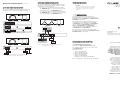
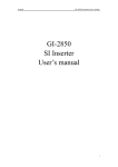
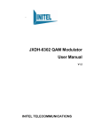
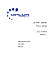
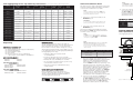
Link Aggregating In-Line Tap Summary Information
See the User Guide for detailed specifications
MODEL
NETWORK
PORTS
TAP
PORTS
PASSIVE
RELAY
FAILOVER
INJECTION
REDUNDANT
POWER
SUPPORTS
POE
RACK
MOUNT
ATAP-100
10/100BASE-T
2 @ 10/100BASE-T
no
yes
yes
no
no
TAP-RMK-3 / TAP-RMK-14
ATAP-101
100BASE-T
2 @ 100BASE-T
yes
n/a
no
yes
yes
TAP-RMK-3 / TAP-RMK-14
ATAP-102
100BASE-T
2 @ 10/100BASE-T
yes
no
no
yes
yes
TAP-RMK-3 / TAP-RMK-14
ATAP-103
10/100BASE-T
2 @ 100BASE-T
no
yes
yes
no
no
TAP-RMK-3 / TAP-RMK-14
ATAP-GIG-BT-BT
10/100/1000BASE-T
2 @ 10/100/1000BASE-T
no
yes
yes
yes
no
TAP-RMK-2
ATAP-GIG-BT-SX
10/100/1000BASE-T
2 @ 1000BASE-SX LC
no
yes
yes
yes
no
TAP-RMK-2
ATAP-GIG-SX-BT
1000BASE-SX
2 @ 1000BASE-T
yes [MM splitter]
n/a
no
yes
n/a
TAP-RMK-2
ATAP-GIG-SX-SX
1000BASE-SX
2 @ 1000BASE-SX LC
yes [MM splitter]
n/a
no
yes
n/a
TAP-RMK-2
ATAP-GIG-LX-BT
1000BASE-LX
2 @ 1000BASE-T
yes [SM splitter]
n/a
no
yes
n/a
TAP-RMK-2
ATAP-2000-BT-BT
2 @ 10/100/1000BASE-T
2 @ 10/100/1000BASE-T
no
yes
yes
yes
no
TAP-RMK-2
ATAP-2000-SX-SX
2 @ 1000BASE-SX LC
2 @ 1000BASE-SX LC
yes [MM splitter]
n/a
no
yes
n/a
TAP-RMK-2
ATAP-2000-LX-SX
2 @ 1000BASE-LX LC
2 @ 1000BASE-SX LC
yes [SM splitter]
n/a
no
yes
n/a
TAP-RMK-2
ATAP-2001-BT-BT
2 @ 1000BASE-T
2 @ 1000BASE-T
no
yes
no
yes
no
TAP-RMK-2
Unpacking
INTRODUCTION
UNIVERSAL PACKING LIST
The Link Aggregating In-Line Taps in this guide are
typically installed between two network end-point devices:
server and switch; two switches; or router and switch.
For information on devices that are designed to connect
with unidirectional data streams, such as SPAN ports, refer
to the Fluke Networks line of Link Aggregating SPAN Taps.
•
•
•
•
•
(1)
(2)
(1)
(1)
(2)
Link Aggregating In-Line Tap (see models below)
Switching AC Adapters
Quick Installation Guide
User’s Guide
AC Power Cords* (for power redundancy)
* (1) AC Power Cord for ATAP-100 and ATAP-103
ATAP-100 SERIES MODELS
ATAP-100
ATAP-101
ATAP-102
ATAP-103
ATAP-GIG SERIES MODELS
ATAP-GIG-BT-BT
ATAP-GIG-SX-SX
ATAP-GIG-LX-BT
ATAP-GIG-SX-BT
ATAP-GIG-BT-SX
ATAP-2000 SERIES MODELS
ATAP-2000-BT-BT
ATAP-2000-SX-SX
ATAP-2000-LX-SX
ATAP-2001-BT-BT
Link Aggregating In-Line Taps:
• Flawlessly combine the separate streams
of a full-duplex link
• Provide two identical tap ports for easy 24x7
scrutiny with multiple single NIC monitoring devices
• Eliminate link access and SPAN port contention
• Are non-intrusive and fault-tolerant; if power is lost,
network traffic continues to flow
• Allow the monitoring of redundant links using
a single analyzer
RACK INSTALLATION METHODS
Prior to installation, refer to the table above to
determine which Rack Mounting Kits are compatible
with the included thumbscrew mounting bracket on
your Link Aggregating In-Line Tap.
Figure 1. ATAP-100 series tap units shown mounted in
optional 3-bay (TAP-RMK-3) Rack Mounting Kit.
General Installation Notes
This quick reference guide is abbreviated for proficient
network technicians; detailed installation information
on each model is found in the User Guide.
NOTE
End-device LINK LEDs must indicate “LINK” prior
to powering the tap to ensure correct failsafe tap
functionality during loss of power.
1. Connect one of the network cables to the
NETWORK A port.
IMPORTANT
Do not exceed the maximum length between end
points as specified by the media type being used.
2. Connect the other network cable to the
NETWORK B port.
The network is bi-directional Tx/Rx path sensitive.
Both end-device “LINK” LEDs must be illuminated
to indicate correct connection.
NOTE
If “LINK” does not exist, the network connection is
backwards. Reverse NETWORK A and NETWORK B
connections to establish “LINK”.
NOTE
For NETWORK or TAP BASE-T connectors, integrated
LEDs display line status and speed of each port.
Refer to the LED Display Codes table.
5. Connect the other tap cable from the TAP 2 port
connector into the analyzer monitoring NIC.
The TAP 2 LINK LED illuminates, indicating link
has been established between the TAP 2 connector
and analyzer monitoring NIC. The TAP 2 ACT LED
illuminates as data is passed to the TAP 2 analyzer.
LED DISPLAY CODES integrated on RJ45 ports
with link or data
CODE
LEFT LED
RIGHT LED
CODE
LINK
solid green
green
1,000Mbps
DATA
flashing green
orange
100Mbps
N/A
n/a
[off]
10Mbps
ATAP-100 SERIES INSTALLATION
Refer to Figure 2 below for connecting an ATAP-100
series Aggregating In-Line Tap to the network.
NOTE
ATAP-100 series only: Network devices that do not
automatically negotiate Rx/Tx pin-out differences
between devices to establish link typically require
a crossover cable. If needed, connect the crossover
cable as follows:
EQUIPMENT – EQUIPMENT
CROSSOVER CABLE CONNECTION
PC – PC
B
PC/ROUTER – SWITCH
none
SWITCH – SWITCH
A
Figure 2. ATAP-100 series Aggregating Tap functional diagram
Distribution
3. Two power supplies are provided (except for
ATAP-100 and ATAP-103 models). Use both power
supplies to ensure uninterrupted monitoring.
Connect both power supply barrel connectors
into the POWER 1 and 2 ports, respectively, of the
Aggregated In-Line Tap. Plug the power supplies
into the external power source; connect the second
power supply to a different external power source
circuit than the first power supply to eliminate
power as a single point of failure. The POWER 1
and 2 LEDs illuminate, indicating power 1 and 2,
respectively, are on. Either LED not illuminated
indicates a defective power source; replace
immediately to ensure redundant power integrity.
4. Connect one tap cable from the TAP 1 port
connector into the monitoring device NIC.
The TAP 1 LINK LED illuminates, indicating link
has been established between the TAP 1 connector
and IDS monitoring NIC. The TAP 1 ACT LED
illuminates as data is passed to the TAP 1 device.
Full-Duplex
Network Cable
ATAP-100
Tap Cables
Full-Duplex
Network Cable
Protocol Analyzer
Network IDS
Access Switch
Figure 3. ATAP-100 series simple connectivity diagram
General Installation Notes
continued
ATAP-2000 SERIES INSTALLATION
COMPLIANCE TESTING
To connect an ATAP-2000 series Link Aggregating In-Line
Tap, refer to these General Installation Notes as a guide,
in addition to the following notes:
ATAP-GIG SERIES INSTALLATION
To connect an ATAP-GIG series Link Aggregating In-Line
Tap, refer to the General Installation Notes as a guide.
CAUTION
Changes or modifications to this unit not expressly
approved by the party responsible for compliance
could void the user’s authority to operate the
equipment.
1. Connect one of the primary link network cables to
the NETWORK A1 port. Connect the other primary
link network cable to the NETWORK A2 port.
2. Connect one of the secondary link network cables to
the NETWORK B1 port. Connect the other secondary
link network cable to the NETWORK B2 port.
Link Aggregating
CERTIFICATIONS
In-Line Taps
This equipment has been tested and found to
meet the radiated and conducted emission limits for
a Class B product of EN 55022 to the EMC Directive
89/336/EEC requirements.
ATAP-100 SERIES
ATAP-GIG SERIES
This equipment has been tested and found to meet
the immunity levels for Class 1, tested to level 2
for EN 6100-4-2, tested to level 3 for EN 61000-4-3,
tested to level 2 for EN 61000-4-4, and tested to
level 3 for EN 61000-4-5 to the EN 50082-1
requirements and meets the Class A requirements
for EN 61000-3-2 and EN 61000-3-3.
Network B
Switch
Firewall
This equipment has completed the Product Safety
Review and found to meet the Low Voltage Directive
72/23/EEC (1993) requirements.
Figure 4. ATAP-GIG series network-tap simple functional
diagram
ATAP-2000 SERIES
QUICK INSTALLATION GUIDE
PN 2527804
[rev. 4, 9/07]
August 2005
© 2007 Fluke Corporation. All rights reserved. Printed in USA.
All product names are trademarks of their respective companies.
Network
IDS
From other countries:
Switch
Network IDS
Switch
Figure 5. ATAP-GIG series tap-network functional diagram
and simple connectivity reference example
Protocol Analyzer
•
•
•
•
•
•
Canada: 1-800-363-5853
Europe: +44 1923 281 300
Beijing: +86 (10) 6512-3435
Japan: +81-3-3434-0181
Singapore: +65-6738-5655
Anywhere in the world: +1-425-446-4519
Visit our website for a complete list of phone numbers.
Limited Warranty & Limitation of Liability
For operating assistance, sales or service in the USA,
call 1-800-283-5853.
Fluke Networks products will be free from defects in
material and workmanship for two years from the date
of purchase. Parts, accessories, product repairs and
services are warranted for 90 days. This warranty
does not cover disposable batteries, cable connector
tabs, cable insulation-displacement connectors, or
damage from accident, neglect, misuse, alteration,
contamination, or abnormal conditions of operation
or handling. Resellers are not authorized to extend
any other warranty on Fluke Networks’ behalf.
To obtain service during the warranty period, contact
your nearest Fluke Networks authorized service center
to obtain return authorization information, then send
your defective product to that Service Center with a
description of the problem.
Send email to: [email protected].
THIS WARRANTY IS YOUR ONLY REMEDY.
NO OTHER WARRANTIES, SUCH AS FITNESS FOR
A PARTICULAR PURPOSE, ARE EXPRESSED OR IMPLIED.
FLUKE NETWORKS IS NOT LIABLE FOR ANY SPECIAL,
INDIRECT, INCIDENTAL OR CONSEQUENTIAL DAMAGES
OR LOSSES, ARISING FROM ANY CAUSE OR THEORY.
Since some states or countries do not allow the exclusion
or limitation of an implied warranty or of incidental or
consequential damages, this limitation of liability may
not apply to you.
Visit the Fluke Networks website
at http://www.flukenetworks.com/.
USA
Figure 6. ATAP-2000 series functional diagram and simple
connectivity reference example
CONTACTING FLUKE NETWORKS
EVERETT, WA 98206-0777
Protocol
Analyzer
P.O. BOX 777
Firewall
Network A
FLUKE NETWORKS
Switch