1
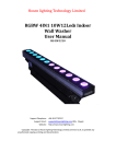
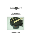
KEEN Projection Media LTD.
INSTALLATION
SWITCH-GLASS
INSTALLATION MANUAL
Please read this instruction manual
carefully before you start installation.
Note: installation requires qualified
electrical work in addition to the regular glass work.
Page
Glass products
1
Edge protectors
2
Framing
3
Joint bars
4
Electrical wiring
5
y2003 KEEN Projection Media, Ltd.
www.keenpm.ca
KEEN Projection Media LTD.
GLASS PRODUCTS:
Clear float glass
3mm
Clear float glass
6mm
Thickness : 6.5mm
LUMP6
Thickness : 10.5mm
LUMP10
Thickness : 12.3mm
LUMP5PWU
Thickness : 12.5mm
LUMP12
Clear float glass
6mm
Tinted glass
3mm
Polished wired glass
6.8mm
Thickness : 6.5mm
LUMBZPP6
Tinted glass
5mm
Tinted glass
6mm
Heat reflective glass
6mm
High performance
heat reflective glass
6mm
Combination
Thickness : 10.5mm
LUMBZPP10
Thickness : 12.5mm
LUMBZPP12
Thickness : 12.5mm
LUMCP6P6
Thickness : 12.5mm
LUMRSP6P6
3mm+3mm
5mm+5mm
5mm+ 6.8mm
11
11
11
Dimensions of
edge protector
(mm)
6mm+ 6mm ,
10
14
16
For maximum sizes, please refer to page 2.
Note: combination of tinted and reflective glass not available.
AVAILABLE SHAPES
≤914
≤914
Flat surfaces only.
≤914
≤2438
≤2438
≤914
≤2438
≤2438
NOT AVAILABLE SHAPES
1
y2003 KEEN Projection Media, Ltd.
www.keenpm.ca
INSTALLATION
Clear float glass
3mm
Clear float glass
5mm
Clear float glass
5mm
KEEN Projection Media LTD.
Please choose one of the following configurations,
requirements.
Double panel
per frame (interior use)
Multiple panels
per frame (interior use)
JOIN
EXTRUSION
INSTALLATION
EDGE PROTECTION
GLAZING TYPE
Single panel
per frame
according to your specific installation
FRAME
POWER
SUPPLY LINES
1m LG. (x2/panel)
H
W
POWER
SUPPLY LINES
1m LG. (x2/panel)
POWER
SUPPLY LINES
1m LG. (x2/panel)
H
JOIN
EXTRUSION
H
W
EACH PANEL MUST HAVE ALL EDGES
PROTECTED
EACH PANEL MUST HAVE ALL EDGES
PROTECTED
Note: When placing the order please specify "interior use" or "exterior use".
When high humidity levels are expected, specify "exterior use" even for panels
destined for interior applications.
Acetic acid-type silicone caulking must not be used for installation !
4 SIDES PROTECTION
WIRES
1m LG.
(x2/panel)
EDGE PROTECTORS
Follow the diagram attached for all
dimmensions required to order the
edge protectors.
3 SIDES PROTECTION
1/2W
H
1/2W
EDGE
PROTECTOR
POWER SUPPLY LINES
Each panel comes with a standard
1m LG. 150mA/110VAC cables
installed along the top edge.
W
INTERIOR AND
EXTERIOR USE
MAX. SIZE
W x H (mm):
1,450 x 3,050
2
y2003 KEEN Projection Media, Ltd.
WIRES
1m LG.
(x2/panel)
WIRES
1m LG.
(x2/panel)
1/2W
EDGE
PROTECTOR
2 SIDES PROTECTION
W
EDGE
PROTECTOR
H
H
EDGE
PROTECTOR
W
INTERIOR USE ONLY
(NO DIRECT EXPOSURE TO WATER OR HIGH
HUMIDITY)
MAX. SIZE
W x H (mm):
1,450 x 3,050
MAX. SIZE
W x H (mm):
1,450 x 3,050
www.keenpm.ca
KEEN Projection Media LTD.
Please select one of the following framing configurations based on your application.
STANDARD OUTDOOR FRAMING:
HOLE c/w
BUSING
BACK BEAD
BACK BEAD
>14
BACK BEAD
>18
6.5
>20
10.5
BACK BEAD
12.3~12.5
BACK BEAD
SILICONE
BACK BEAD
SILICONE
>14
SILICONE
HOLE c/w
BUSING
WIRES
>14
>14
WIRES
BUSHINGS:
FLEXIBLE CONDUIT
JONCTION
BOX
BUSHING
Drill or cut a hole large enough to
install a protective plastic or rubber
bushing for the wires to go through.
1/2
W
Warning: not installing rubber bushings can cause a shock hazard.
DRAINAGE HOLES:
DRAINAGE HOLES
For all exterior applications,
depending on the width of the
panel, cut 3-7 (based on width)
drainage holes at the bottom of
each panel.
3~7
40
40
3
y2003 KEEN Projection Media, Ltd.
www.keenpm.ca
INSTALLATION
HOLE c/w
BUSING
>14
STANDARD DIMENSIONS (mm)
WIRES
6mm + 6mm , 5mm + 6.8mm
5mm + 5mm
>14
3mm + 3mm
>14
GLASS
LAYER
THK.
KEEN Projection Media LTD.
JOINT BARS:
JOINT BAR
ARRANGEMENTS
LUMP6
5
4
12
Airtightness: CLASS2 JIS AI516
CONVEX BAR
CONCAVE BAR 1
Glass layers: 3mm+3mm
Note: use for indoor applications only.
LUMP10
5
CONVEX BAR
JOINT BARS APPLICATION:
1. Install temporarily the glass panels inside the outer
frame.
2. Set the vertical gap between panels at 5mm.
3. Cut the joint bar approx. 1-2mm longer than the
measured length.
4. Install the concave bar between panels.
5. Snap in place and secure the convex bar.
6. Press each panels together inside the joint bar for a
tight fit.
7. Secure the panels inside the frame and apply all
seals.
4
12
Glass layers: 5mm+5mm
LUMP12
5
4
12
PRELIMINARY WIRING:
CONCAVE BAR 2
CONVEX BAR
CONCAVE BAR 3
Glass layers: 6mm+6mm
JONCTION BOX
WIRES
FLEXIBLE
CONDUIT
Attached diagram describes the main
components for preliminary wiring of
a single or multiple panels.
BUSHING
ROCK NUT
ROCK NUT
BUSHING
WIRING DUCT
BUSHING
Alternative components can be used
as approved by a certified electrician
and a qualified glass installer.
CLOSING CAP
GLASS
4
y2003 KEEN Projection Media, Ltd.
www.keenpm.ca
INSTALLATION
For butt joint connections, specially designed
transparent plastic joint bars shall be installed
between the panels.
KEEN Projection Media LTD.
ELECTRICAL WIRING:
Panels must be powered at a voltage between 65VAC and 100VAC.
Note that transparency increases with the voltage.
Any voltage bellow 65VAC would not turn ON the panels.
POWER
SUPPLY
CIRCUIT
BREAKER
SWITCH
INSTALLATION
Note: electrical wiring must be performed by a certified electrician.
JUNCTION
BOX
TRANSFORMER
20VA/sq.m.
PANEL WIRES
Transformer should provide 65-100VAC at the
secondary.
Transformer shall supply 20VA/sq.m. for each
individual panel required to operate.
Always place the switch or any controlling
device on the transformer primary.
ACTIVE
GLASS
Warning!
A switch installed on the transformer
secondary can damage the active panels.
GROUND
Circuit breaker should be sized and installed
according to local electrical codes.
Circuit breaker must be installed anytime the
active panels may be exposed to water or high
humidity levels (i.e. outdoor installation, near
bathrooms or kitchens).
When active glass is encased within an
electrically conductive material, the frame must
be connected to the ground.
Refer to the diagram below for the
independent operation of single or
multiple glass panels.
POWER
SUPPLY
POWER
SUPPLY
NOTE:
This configuration allows the remote
control of panels using: timers, sensors,
PLCs, etc.
5
y2003 KEEN Projection Media, Ltd.
SWITCH
TRANSFORMER
GLASS
TRANSFORMER
GLASS
TRANSFORMER
GLASS
TRANSFORMER
GLASS
SWITCH
GLASS
GLASS
www.keenpm.ca