1
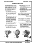
TUBE-O-THERM® Gas Burners
Page 2750-S-1
Installation Instructions
General Instructions
Important: Do not discard packing material until
all loose items are accounted for.
To prevent damage in transit, the spark ignitor,
mounting gaskets, and connecting linkage components may be packed separately and shipped loose
with your new Maxon TUBE-O-THERM® Burner.
The burner itself is normally only a part of your
complete combustion system. Additional pipe train
accessories and control components will be required
for a complete system installation.
TUBE-O-THERM® Burner provides the air supply
(unless it is EB version, which requires a separate
combustion air blower). It also serves as a fuel flow
control and fuel/air mixing device.
Burner should not be exposed to direct radiant heat
or positioned where it might draw in inert gases. If
such conditions exist, consider filters, relocation, and/
or use of the EB version and external air supply.
Electrical service must match the voltage, phase,
and cycle of all electrical system components and be
compatible with burner nameplate ratings. Insure that
all normal control safeguards are satisfied. Combustion air blower should continue to run after shutdown
to allow burner to cool.
NOTE: Burners supplied with standard blower
motors have dual voltage capability (230/460v/
3 Ph/60 Hz; 115/230v/3 Ph/60 Hz; 190/380v/3 Ph/
50 Hz). Failure to connect plant voltage to proper
fan wiring will result in poor burner performance.
Refer to wiring diagram on fan motor.
Gas supply piping must be large enough to
maintain the required fuel pressures cataloged for the
particular burner size used with burner operating at
full-rated capacity.
Anything more than minimum distance or piping
turns may necessitate oversizing piping runs to keep
pressure drops within acceptable ranges.
Inlet pipe leading to any burner should be at least
four pipe diameters in length. If multiple burners are
fed from a single gas train, care should be taken to
minimize pressure drop and give maximum uniformity.
NOTE: Multiple burner installations fed by a single
pipe train should incorporate a balancing valve and a
swing check valve installed as close as possible to
each burner gas inlet for improved heating uniformity
and more dependable light off. Otherwise, gas
manifold may act as a reservoir, preventing reliable
light off during trial for ignition period of your control
panel sequence.
10/99
Clean fuel lines are essential to prevent blockage
of pipe train components or burner gas ports.
Main shut-off cock should be upstream of both
the main gas regulator and pilot line take-off. Use it to
shut off fuel to both pilot and main burner during shutdown periods of more than a few hours.
The fuel throttling valve contained within a
Maxon burner is not intended for tight shut-off.
Main gas regulator is essential to maintain a
uniform system supply volume and pressure. If one
pipe train supplies multiple burners, provide a separate regulator in the branch leading to each burner
system.
It is recommended that the regulator be sized for at
least 120% of full system capacity at the required
pressure, carefully considering pipe train losses.
Follow the instructions attached to the regulator
during installation. Refer to page 2758 for burner inlet
pressure requirements.
Pilot take-off should be upstream of the main gas
regulator, but downstream of the main gas cock. It
should normally include its own pilot gas regulator, a
solenoid valve and shut-off cock. The pilot adjustable
orifice at the pilot inlet simplifies adjustment.
NOTE: Most regulator manufacturers include an
internal relief valve in their standard regulators. These
relief valves will begin to vent when the downstream
pressure is somewhere around 7 inches w.c. greater
than the regulator set pressure. Regulators can be
ordered without an internal vent. The best option is to
run the pilot interrupted. If the pilot is not interrupted,
catalog minimums cannot be obtained.
Pilot piping must be large enough to provide for
the full flow and pressures shown in the catalog for
your particular burner size. Pilot solenoid should be
located within 5 feet of burner to allow gas to reach
burner before flame safeguard “times-out”.
The 3/8" pilot connection of the TUBE-O-THERM®
Burner is adequate for the pilot gas flows shown, but
care must be taken to assure that the required gas
pressure (8-12" wc) and flow are available at pilot
inlet.
Fuel Shut-Off Valves (when properly connected to
a control system) shut the fuel supply off when a
hazardous operating condition is sensed. Manual
reset valves require operator attendance each time
the system is started up (or restarted after a shutdown). Motorized shut-off valves permit automatic
start-restart when used with an appropriate control
system.
Maxon practices a policy of continuous product improvement. It reserves the right to alter specifications without prior notice.
INDUSTRIAL COMBUSTION EQUIPMENT AND VALVES
m
CORPORATION
MUNCIE, INDIANA, USA
TUBE-O-THERM® Gas Burners
Page 2750-S-2
Installation Instructions
Test connections are essential for burner adjustment. They should be provided immediately downstream of the regulator and are included in the burner
itself.
Test connections must be plugged except when
readings are being taken.
Horizontal mounting of the burner is preferred,
but burner may be mounted in any position suitable
for automatic control motor and UV scanner.
Burner mounting requires a standard 150# flange
to fit the burner’s studs (four studs for 3" burner, eight
studs for 4", 6" and 8" burners). Burner mounting
gasket is a standard 150# flange gasket (supplied by
Maxon). Although the mounting uses standard ANSI
dimensions, metric bolts are used for the burner
mounting. Therefore, Maxon will supply metric nuts
with the burner. Customer should apply an anti-seize
thread lubricant to mounting bolts before installing
burner onto flange connection.
After placing burner in position, add lock washers
and nuts, then draw up hand-tight only. Check that
burner is centered, then tighten all nuts firmly.
For proper performance of any burner, air inlet and
motor should be surrounded by clean, fresh, cool air.
Burner and pipe manifold support will be required to support weight of the burner and connected
pipe train components. Air control motors, in particular, require additional support. Maxon connecting
base and linkage assemblies are designed to position
the control motors to work with the burner, not to
support their weight.
The TUBE-O-THERM® Burner may require external
auxiliary support provided by the user. Additional
burner support may be required in conjunction with a
stiffener plate when mounting TUBE-O-THERM®
Burner onto tube or thin tank walls.
Protective covers for burner should be added in
the field if exposure to dripping condensate, splashing
flux, exhaust steam, etc. is unavoidable. Any such
cover should be removable to provide access to
burner and should not interfere with control linkage
motion, observation port viewing or air inlet.
Flame sensing is accomplished by a UV scanner.
Keep scanner as close to burner as feasible. Do not
use cooling air to scanner port. Heat block, if used,
may affect signal strength with some brands of
scanners.
Alternate fuels may require correction of supply
pressures.
Multi-burner installations require special considerations if supplied by a common pipe train and/or air
supply.
m
CORPORATION
MUNCIE, INDIANA, USA
Air and Gas Balancing Valves should be used for
improved heating uniformity; Gas Swing-Check
Valves should be installed as close as possible to
each burner inlet for dependable light-off (gas manifold may otherwise act as a reservoir, preventing lightoff during trial-for-ignition period).
Control system’s circuitry must not allow main
Fuel Shut-Off Valve to be opened unless combustion
air is on, and must de-energize valve upon loss of
combustion air pressure, along with the other usual
system interlocks. Motor starter is to be interlocked
with valve, whether or not a combustion air pressure
switch is used.
Because of the high firing rates possible with this
burner and the low cross-sectional area of the
tubes, no draft or chimney effect should be designed for, or expected, if the exhaust stack
diameter is equal to the fired tube diameter.
Immersion tubes are usually vented to the
outdoors, except for those in highly ventilated areas
such as a plating room with continuous high volume
exhaust. An exhaust fan may be required if the
building is under negative pressure. Exhaust is
normally diluted to avoid the need for high
temperature fans, but adequate make-up air must be
available.
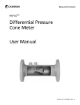
This diluting can be done with an open tee installed
in a vertical run (or in a horizontal run with the open
end down), but such a system mixes slowly.
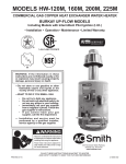
An adjustable hood (shown in sketch below) offers
much better performance. In all cases, care must be
taken that all products of combustion are exhausted
from the building.
Cross-sectional area of the exhaust hood should
be a minimum of 1.5 times the fired tube crosssectional area.
Maxon practices a policy of continuous product improvement. It reserves the right to alter specifications without prior notice.
INDUSTRIAL COMBUSTION EQUIPMENT AND VALVES
TUBE-O-THERM® Gas Burners
Page 2750-S-3
Installation Instructions
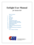
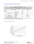
Wall mounting installation (recommended) and stub mounting
The TUBE-O-THERM® Burner was designed to
transfer heat to your process as efficiently as possible. As a result, your process tube, which bolts to
the outlet of the TUBE-O-THERM® Burner, can
become hot during the burner’s operation.
On optional stub mounted versions, the inlet
portion of this tube will overheat if it extends too
far outside the tank.
The maximum recommended length for the initial
portion of your process tube outside the tank is
shown:
Burner flange to inside of tank wall (maximum):
Dimension “C”
3” burner
2.5”
Dimension “C”
4” burner
2.5”
Dimension “C”
6” burner
2.5”
Dimension “C”
8” burner
3”
Stub mounted installation
A
C
B
TUBE-O-THERM®
Burner
Tank Wall
(inside)
Tank Wall (outside)
Hex Nut
Immersion Tube
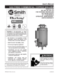
For most applications, the wall mounting option
is recommended. Use of the wall mounting option
will support the burner off of the tank, instead of
supporting the burner with the tube. Maxon also
suggests using a burner support independent of the
flange, which will allow for some expansion during
firing. Consult your Maxon representative for more
information.
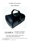
To install the wall mounting:
1. Insert the immersion tube through the tank wall,
making sure that it extends no more than 1/2" past
the outside of the wall (the tube should be as flush
as possible with the Wall Mounting Plate once it is
installed).
2. Weld the immersion tube to the tank wall.
3. Slip the Wall Mounting Plate over the immersion
tube (with the screw heads facing the tank wall)
and seal weld the I.D. to the tank wall.
Optional: Continuous weld the O.D. of the mounting plate. If I.D. is seal welded, O.D. should be
intermittant welded for rigidity and strength.
4. Attach the burner to the mounting bolts.
Wall mounted installation
TUBE-O-THERM® Burner
Tank Wall (customer’s)
immersion tube should extend no more than 1/2" past this outside wall
Wall Mounting Plate (Maxon) (to be welded to customer’s tank)
Gasket (Maxon) high temperature RTV applied between burner body and gasket only
Existing Weld - tank wall/tube
Immersion Tube (customer’s)
As an option to seal welding the O.D. of the mounting
plate, customer can seal weld the I.D. to prevent leakage
of hot products of combustion.
8/00
I.D. of Maxon supplied mounting plate is 3/4" larger
than O.D. of tube. This is to allow a gap for weld
clearance where the tube welds to the tank wall
Maxon practices a policy of continuous product improvement. It reserves the right to alter specifications without prior notice.
INDUSTRIAL COMBUSTION EQUIPMENT AND VALVES
m
CORPORATION
MUNCIE, INDIANA, USA
TUBE-O-THERM® Gas Burners
Page 2750-S-4
Start-Up Instructions
Read complete instructions before proceeding,
and familiarize yourself with all the system's equipment components. Verify that your equipment has
been installed in accordance with the original manufacturer's current instructions.
CAUTION: Initial adjustment and light-off
should be undertaken only by trained and
experienced personnel familiar with combustion systems, with control/safety circuitry, and
with knowledge of the overall installation.
Instructions provided by the company and/or
individuals responsible for the manufacture
and/or overall installation of complete system
incorporating Maxon burners take precedence
over these provided by Maxon. If Maxon
instructions conflict with any codes or regulations, contact Maxon Corporation before
attempting start-up.
For initial TUBE-O-THERM®Burner start-up:
1. Close all burner fuel valves and cocks. Make
preliminary adjustments to fuel gas regulators.
Remove pilot and main gas regulators' adjusting
screw covers. Turn adjusting screw down (clockwise) to approximately mid-position. Close pilot
gas adjustable orifice screw by turning in clockwise until it stops. (Do not over-tighten.) Then
back out the adjustable orifice (counter-clockwise)
approximately 2-3 turns.
2. Check all electric circuitry. Verify that all control
devices and interlocks are operable and functioning within their respective settings/ranges. Be
sure all air and gas manifolds are tight and that
test ports are plugged if not being used.
3. Check that the immersion tube stack damper
is fully open and locked into position. Stack
dampers not required and can block exhaust even
if open.
4. Check that air and gas pressure switches are
not marginally set to prevent troublesome system
shutdown during start-up. Set pressure switches
with some cushion for start-up and re-adjust
during final system tuning.
5. Disconnect the automatic control motor's
linkage from your TUBE-O-THERM®Burner's
operating crank arm by loosening the control
motor's connecting rod from the burner's linkage.
m
CORPORATION
MUNCIE, INDIANA, USA
Initial start-up adjustment should only be
accomplished during a manual burner control
mode.
6. Start all system-related fans and blowers.
Check for proper motor rotation and impeller
direction. Verify that all control interlocks are
working. Allow air handling equipment to run for
adequate purge of your manifolds and immersion
tubes. With main gas shut off, manually advance
TUBE-O-THERM®Burner's operating crank to
high-fire position (90) so that air only flows
through burner and immersion tube.
CAUTION: Do not bypass control panel timers
typically controlling sequential operations.
7. Determine the required gas pressure from
chart on page 2758.
NOTE: Gas pressures (shown on page 2758) are
under actual high-fire conditions, once proper
differential air pressure has been established.
8. Verify that spark ignitor is properly positioned
and bottoms out inside the burner air plate.
NOTE: Field experience shows that a full-wave
spark ignition transformer provides a reliable
ignition source.
9. Return burner control valve/crank to low-fire
position when purge of system is complete.
10. Open main and pilot gas cocks, activate spark
ignition transformer and pilot gas solenoid valve,
then attempt pilot ignition to light pilot while slowly
turning pilot gas regulator and/or adjustable orifice
screw counter-clockwise to increase fuel flow.
Repeat procedure as necessary until pilot ignites,
as air might have to be bled out of fuel supply
lines before reliable pilot flame is established.
Pilot gas regulator should normally be set for as
low a pressure as possible, using fuller opening of
pilot gas adjustable orifice.
11. After ignition, adjust pilot to provide pilot gas
pressure as specified on page 2758. Use a pilot
gas pressure regulator that provides 8-12" wc gas
pressure to the pilot gas inlet.
Maxon practices a policy of continuous product improvement. It reserves the right to alter specifications without prior notice.
INDUSTRIAL COMBUSTION EQUIPMENT AND VALVES
TUBE-O-THERM® Gas Burners
Page 2750-S-5
Start-Up Instructions
12. Re-check pilot ignition by closing pilot gas cock
or otherwise causing pilot outage. Re-light and
refine pilot gas adjustment as necessary to get
ignition within a second or two. The flame safeguard relays should now power your main fuel
Shut-Off Valve(s).
CAUTION: After completing previous steps, recheck all interlocking safety components and
circuitry to prove that they are properly installed, correctly set, and fully operational. If in
doubt, shut the system down, close pilot cock
and contact responsible individual before
proceeding further.
13. Establish main flame. With burner at low-fire
position, back out main gas pressure regulator
adjusting screw (counter-clockwise) to get lowest
outlet pressure possible. Open all manual fuel
shut-off valves (automatic fuel shut-off valve
should already be open) so gas flows to burner
inlet. There should be little, if any, change in
flame appearance. Turn main regulator adjusting screw in (clockwise) until gas pressure at the
burner inlet (upstream of the burner) is as specified on page 2758. Main flame should now
appear larger than pilot-only flame.
At cold start-up, some rumbling will occur as the
tube warms up. To reduce or prevent this rumbling,
a low-fire time period of approximately 2 minutes
before continuing on to high fire is recommended.
14. Establish high-fire setting by slowly moving
burner crank toward high fire position while
observing gas pressure at burner gas test inlet.
Refine main gas regulator adjustment as necessary to provide correct differential gas pressure at
high fire. If pressure cannot be adjusted high
enough, a different regulator or regulator spring
may be necessary. Do not, however, exceed
6" wc pressure drop between regulator outlet and
burner inlet.
CAUTION: If burner(s) go out, close shut-off
valve or shut main gas cock at once. Return to
minimum setting, re-light pilots if necessary,
then turn main gas on again. Check carefully
that every burner is lit before proceeding.
2/98
Cycle burner from minimum to maximum
and refine adjustment, if necessary.
For operation with interrupted pilot, shut off
pilots and cycle burner from minimum to maximum and back several times to verify the flame is
maintained.
15. When burner performance is satisfactory and
stable throughout the firing range, reconnect
linkage to control motor.
Control linkage travel must be such that burner
crank is moved throughout its complete travel, or
cataloged capacities and turndowns will not be
achieved.
16. If attempts to start-up burner have been
unsuccessful to this point, refer to Service Tips on
pages 2750-S-6 and 7.
NOTICE: If less than full-rated burner capacity is
required, adjust control motor and/or motor/gas
shaft linkage to limit maximum output. Do not
adjust gas/air linkage.
CAUTION: Do not limit capacity by adjusting gas
pressure to the burner inlet. The internal gas
valve is characterized to the air butterfly valve
and is based on the specified inlet gas pressures.
Operation outside of these specifications will
result in unsatisfactory burner performance.
With interrupted pilot, it may be necessary to
set control for somewhat higher than minimum
burner setting to permit hold-in of flame detection
system without pilot.
CAUTION: Internal drive mechanism within the
control motor may be damaged if linkage is
adjusted so as to cause binding with burner in
high or low fire position.
17. Re-check differential gas pressure with unit at
operating temperature. Refine high-fire setting if
necessary, considering differential pressure,
flame stability, and appearance. Dust or contaminants in the air stream may affect flame appearance.
18. Plug all test connections not in use to avoid
dangerous fuel leakage. Replace equipment
cover caps and tighten linkage screws.
Maxon practices a policy of continuous product improvement. It reserves the right to alter specifications without prior notice.
INDUSTRIAL COMBUSTION EQUIPMENT AND VALVES
m
CORPORATION
MUNCIE, INDIANA, USA
TUBE-O-THERM® Gas Burners
Page 2750-S-6
Start-Up Instructions
19. Check out overall system operation by cycling
through light-off at minimum, interrupting pilot,
and allowing temperature control system to cycle
burner from minimum to maximum and return.
NOTE: Typical gas firing control sequence for
Maxon burner is provided only as a guide. Instructions provided by complete system manufacturer
incorporating Maxon burners take precedence.
Light-off:
1.
2.
3.
4.
5.
6.
For gas firing
TUBE-O-THERM®Burner
Shut-down:
Close cocks, shut-off valve(s)
1. Close main &
Verify burner at low fire
pilot gas cocks
Start recirculating/exhaust fans 2. Keep combustion
Start burner blower
air blower running
Purge at least 4 air changes
after shut-down long
Open pilot & main gas cocks
enough to allow
burner to cool
Recheck all safety system interlocks for
proper setting and operation.
WARNING: Test every UV installation for
dangerous spark excitation from ignitors and
other possible sources of direct or reflected UV
radiation. Use only gas-tight scanner
connections.
20. Before system is placed into full service,
instruct operator personnel on proper start-up
operation with shut-down of system, establishing
written instructions for their future reference.
Service Tips
On occasions during cold start-up, a rumbling will
occur in the tube until thermal equilibrium is established. This is normal and should disappear within a
few minutes. A low-fire time period of approximately 2
minutes is recommended prior to high-fire operation.
If, after several minutes of high-fire operation the
rumbling has not decreased or the burner exhibits
flame instability, shut off the burner and perform the
following checks:
1. Start all system-related fans and blowers to
duplicate conditions from step 6 of start-up
instructions on page 2750-S-4. Advance burner
operating crank to high-fire position.
2. Determine and verify differential air pressure
at burner backplate test ports.
Connect a manometer between the gas test
port and the air test port. With the burner
operating crank at high-fire position, fuel valve(s)
closed, air handling systems and combustion air
blower on, the manometer will read the differential combustion air pressure.
Air test port should be connected to the (+)
end of the manometer as it will have the higher
pressure over the gas test port.
m
CORPORATION
MUNCIE, INDIANA, USA
TUBE-O-THERM®
Burners
Maxon practices a policy of continuous product improvement. It reserves the right to alter specifications without prior notice.
INDUSTRIAL COMBUSTION EQUIPMENT AND VALVES
TUBE-O-THERM® Gas Burners
Page 2750-S-7
Service Tips (continued)
NOTE: The chart below shows normal differential
combustion air pressure readings in a no-fire
condition. These readings will increase when
burner is firing. The fuel gas pressures shown are
at high fire condition.
Size
3"
4"
6"
8"
Burner
Model Pkg EB Pkg EB Pkg EB Pkg EB
Differential Air
Pressure ("wc)
1.5 2.8 1.3
2.8
2.1
3.9
1.4
2.7
Natural Gas
32.1 59 25.8 56.9 29.2 62.1 33.0 72.0
Pressure ("wc) [1]
Propane Gas
13.6 29 12.9 28.4 15.4 33.7 16.5 37.0
Pressure ("wc) [1]
[1] at burner gas test por t
If your reading is higher than these cold air
pressure readings, you have a suction in your tube.
This condition should not be a problem.
If your reading is lower than the cold air
differential pressure reading, you have a back
pressure in your tube.
If an exhaust stack damper is used, check that it
is fully open and locked in place.
Excessive back pressure can cause high CO
emissions, smoke and carbon in firing tube and will
restrict firing capacity of burner.
NOTE: The differential air pressure setting
determines the burner's capacity and performance capabilities.
NOTICE: Burner performance can be drastically
affected by tube configuration and static
conditions within tube created by dampers in
exhaust stack.
3. All TUBE-O-THERM® Burners are shipped with
the air/gas linkage factory set. Check centerline to
centerline dimensions on the air/gas linkage to
determine that it is the proper length per dimension B shown on pages 2759-2761. The linkage is
fabricated as a turnbuckle-style link. To adjust,
simply loosen the locknut and twist the arm
clockwise to shorten, or counter-clockwise to
lengthen the linkage.
4. If air/gas linkage dimension is correct per dimensions shown on pages 2759-2761, check wiring
diagram to blower motor to determine that dual
voltage motor has been wired properly. Failure to
do so will result in differential air pressure readings that are out of specification. Correct wiring
errors as necessary.
5. If stack damper is used in error, make certain it is
full open and locked (may need to be removed).
Additional Service Tips
Problem
Cause(s)
Pilot fails to light.
1. On initial start-up, gas line may be filled with air. Repeat ignition
trial several times to purge.
2. No power to ignition transformer or pilot solenoid.
3. Open circuit between ignition transformer and ignitor plug.
4. Pilot gas cock adjusting screw closed.
5. Insufficient gas pressure into or out of pilot regulator.
Main flame fails to light or goes out
as burner cycles to high fire.
1.
2.
3.
4.
Burner is unstable or produces
soot, smoke or excessive carbon
monoxide.
1. Gas/air ratio out of adjustment. Adjust fuel pressures and/or air
linkage as instructed under Service Tips.
2. Air filter to combustion air fan is plugged or dirty. Replace or clean.
3. Exhaust stack damper is closed or partially closed, or another
restriction exists in the fired tube system.
10/99
Insufficient pressure into or out of main gas regulator.
Marginal air pressure switch setting.
Marginal gas pressure switch setting.
Incorrect combustion air pressure.
Maxon practices a policy of continuous product improvement. It reserves the right to alter specifications without prior notice.
INDUSTRIAL COMBUSTION EQUIPMENT AND VALVES
m
CORPORATION
MUNCIE, INDIANA, USA
TUBE-O-THERM® Gas Burners
Page 2750-S-8
Notes
m
CORPORATION
MUNCIE, INDIANA, USA
Maxon practices a policy of continuous product improvement. It reserves the right to alter specifications without prior notice.
INDUSTRIAL COMBUSTION EQUIPMENT AND VALVES