1
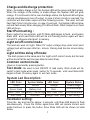
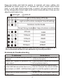
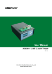
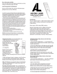
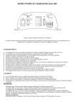
SOLAR CHARGE CONTROLLER
USER MANUAL
Charge and discharge protection:
When the battery charge is full, the System LED will be green and flash slowly.
When the voltage of the battery is undervoltage, the System LED will glow
orange. If it continues to fall to over-discharge status, the System LED will glow
red and simultaneously turn off output. In case of short circuits or overload, the
controller will shut down output until the following sunrise . The Load Led will
flash fast if short circuits occur. in case of overload, the System LED will glow
red and flash slowly.When charging,PV LED will flash. When Output is on,Load
LED will be on.
Start Point setting :
Press button for ten seconds until PV State LED begins to flash, and System
State LED and Load State LED will be out.Pressing button again will save
current PV voltage as start point to memory.
Light on/off control mode:
The load will work all night. When PV output voltage drop under start point
voltage,load will be open after ten minute. Closing load has ten minute delay
also.
Light on/time delay off mode:
The start process is the same as in the ‘Light on/off control’ mode, but the load
will be shut off at the set time (see table to select time).
Common control mode:
.Open or close load by pressing button.
Test mode: Be used to test ON/OFF of load easily .Work mode will be
switch to test mode when press button for 15 seconds until Load State LED
begins to flash.Press key again to exit test mode.
System Led Description:
System Status
LED Color
LED Color
System Status
Undervoltage
Green
Orange
Normal
Overdischarge
Green Flash
Red
Battery Full
Green Flash fast Battery overvoltage Red Flash Fast Overtemperature
Fuse fusing
Orange Flash Fast
Overload
Red Flash
Parameter setting:
Press the key and hold for approx. 5 seconds until three LED begins to flash
simultaneously . Press the button again,three LED will denote current work
mode.Continue to press the button,three State LED will be shown as table
below.
1
Press the button and hold for approx. 5 seconds will save setting into
EEPROM.No button press for 15 seconds will return normal status.Press
theif it is A2,light on/off control mode is cancel. A2 type,if want to set time
B,firtly change woke mode to light on/off control mode and save it.then,you can
adjust second load on time.
LED ligh t
LED off
Light on/time delay off mode
Light on/off control mode(A2 Time B Setting)
Common control mode
Time(Timing mode) Bat. Cap.(Common control)
4 Hours
17AH
5 Hours
40AH
6 Hours
80AH
8 Hours
150AH
10 Hours
200AH
Note:use customized communication device to connect computer,and
use customized software to set parameter by friendly interface.
Problems & Troubleshooting
Solutions
Problems
The PV LED if off when sunlight falls on
PV panel.
System LED is green or yellow but no
power output.
Check if the solar panel’s cables are
connected properly.
Check the load’s cables are connected
to the system properly.
Check output circuit of load for short
System LED flashes red but there is no circuit or overload. Re-connect the Bat.
power output, or LOAD LED flash fast. again to reset the system or wait until
the next day.
System LED is red but there is no
The Bat. is over-discharged. Wait until
power output.
the system has recharged the battery.
2
Features:
1. Automatic boost, recovery and float charging capacities for extended
battery life (use temperature compensation).
2. Over-discharging control voltage modified by the battery discharging rate
curve.
3. Protected against overload, internal and external short circuits, reverse
connection, thunder and lightning, and PV panel reverse current.
4. Clear LED display for reliable reporting of the system’s condition.
5. Industry standard production ensures durability and efficiency.
Comfortably operate within a wide temperature range.
6. Uses EEPROM memory to save all work.
7. Control point instead of adjustable resistance to protect the control work
point from temperature and vibration fluctuations.
8. PWM high efficiency charging is recommended for optimal operation.
9. System parameter can be set by computer through serial comnication.
Installation:
1. Prepare wire. Choose a plastic coated copper wire .Cut the wire to the
shortest length possible, then peel 5mm of plastic from end.
2. Connect exposed end of wire to battery port of controller, and then with the
battery, paying careful attention to the +/- poles of the connection (if the poles
are reversed, the controller won’t be damaged but it won’t work).
3. Repeat wire preparation and connect wire to solar panel port of controller,
and then to solar panel. If connection is correct and the PV panel is exposed
to sunlight, the charging indicator will glow green.
4. Repeat wire preparation and connect the load to the load port of controller,
again taking care to correctly connect the +/- poles.
Caution: If the system voltage is above 24V, avoid touching any
conductor with bare hands during installation in case of electrical
shock.
3
133mm
60mm
BUTTON
PV LED
System LED
Solar Charge Controller
+
-
+ - + - + - +
PV BAT. LOAD
-
+
-
+
-
+
-
Load LED
COM
LOAD--A1
LOAD B--A2
Rs485 Port-A6
Note:
A6 controller,A and B port of RS485 interface must be connected
by A-A and B-B.
**A1 ,A2 controller can be connect to computer by COM port
when controller is not installed.
**COM port only receive TTL level.
**If system voltage is 36V or 48V,please connet PV to controller
correctly.reverse connect may break controller.
**If bat voltage is lower than 10V,controller may be out of work.
**D1 type +,- port must connect DC by Power Transformer.
4
Specifications
TYPE
Rated charge current
Rated load current
Load protection
A1
A6
A2
20A
10A
15A
20A
10A
15A
1.25 times of rated load current 60 sec, 1.5 times of
rated load current 5 sec, overload protectionwill be
triggered.Over 3 times of rated load current.short
circuit protection will be triggered.
<5mA
-35℃ to +50℃
Quiescent current
Work temperature
12V
24V
Over voltage protection
17.0V
34.0V
Work voltage
D1
5A
5A
36V
48V
51.0V
68.0V
59.2V
Boost charge voltage
14.8V
29.6V
44.4V
Direct charge voltage
14.4V
28.8V
43.2V
57.6V
Float charge voltage
13.7V
27.4V
41.1V
54.8V
Lower voltage indicate
12.0V
24.0V
36.0V
48.0V
Over discharge voltage
11.1V
22.2V
33.3V
44.4V
12.6V
25.2V
37.8V
50.4V
Over discharge return
voltage
Temp compensation
-3mv/℃/2V
Real clock
Comunication
Load
Real clock
Real Time
Off Line
Two Independent
load output
Two Shunt
load output
One load
Direct current or preset frequency output
Dimension
145*92*29mm
Weight
150g~250g
5