1
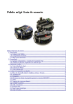
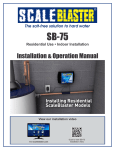
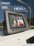
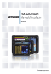
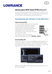
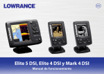
Pub. 988-0152-071 Addendum I Additional Instructions for Lowrance M52i S/GPS Your sonar/GPS unit, the M52i, functions exactly like the M52 described in the manual provided (part 988-0152-001). In addition, the M52i contains a communications port for NMEA 0183 output. The instructions for connecting data cables and setting up the communications port appear in this addendum. NMEA 0183 Data Cable Connections NMEA is a standard communications format for marine electronic equipment. The M52i can send information to any device that receives NMEA 0183 data. This allows the unit to work with VHF marine radios equipped with the Digital Selective Calling (DSC) distress call feature. To send NMEA 0183 data, the M52i has one NMEA 0183 version 2.0 communication port. The com port can be used to send NMEA formatted data such as your current position. The provided M52i data cable plugs into the accessory socket on the right side of the back of your unit's case. The data cable ends in two wires that connect to your VHF radio or other NMEA device. The M52i uses the yellow wire to transmit and the black shield wire for signal ground. NOTE: Some VHF radios, such as the popular Uniden brand, have input levels which require use of an additional diode and resistor built into the M52i data cable. This is Wiring Diagram A, which is described on page 2. The majority of the DSC radios will work with the resistor and diode as provided by Lowrance Electronics. A few other radio brands (and other electronic devices) that meet the NMEA 0183 standard won't need these adapters and you will have to remove the resistor and diode to make those work. This is Wiring Diagram B, which is described on page 3. Consult your other device's owner’s manual, then read through all of the following instructions before you begin. Use the installation diagram most suited to your brand of radio or other device. If your device 1 manual indicates an RS-232 connection (i.e., a computer), remove the resistor and diode and connect using Wiring Diagram B. Most other connection types (TTL; NMEA + and NMEA –; differential) will require Wiring Diagram A. Recommended Tools and supplies Recommended tools for this job include: wire pliers or wire stripper and a wire cutter. Required supplies for this job include: two gray (18 gauge) or blue (16 gauge) wire nuts and electrical tape. Supplies are not included. Wiring Diagram "A" Begin by stripping the wire ends of the device you're connecting to the M52i. (You'll notice the M52i's data cable comes pre-stripped, with wire ends exposed.) Use wire pliers to strip about 1/4-inch (6.35 mm) of insulation from each of the radio's or other device's data wires. Strip the ends of the VHF radio's data wires. Connect them to the prestripped wires of the M52i's data cable (shown right). Twist the exposed wires together as shown in the following figures. If you're using a Uniden or similar radio, connect the radio's NMEA Wire to the M52i data cable's yellow wire, and the radio's Ground/Shield wire to the M52i data cable's black shield wire. If you're using another radio brand or NMEA device, see Wiring Diagram B instructions at the end of page 3. Yellow (Transmit) Com port to M52i Shield (Ground) NMEA Wire (Receive) or NMEA + Ground/Shield or NMEA – To Uniden radio or other device Com port wiring to transmit NMEA information to a Uniden or similar VHF radio or other device. 2 Twist the appropriate wires together, making sure that the exposed ends make good contact. Secure the wire ends with wire nuts, then wrap each wire nut securely with electrical tape to protect against moisture, as shown in the figure on the right. After taping the wire ends individually, wrap the entire connection with electrical tape as shown. This will help protect from moisture and prevent the wires from breaking contact. Wiring Diagram "B" If your VHF radio or other device requires true RS-232, you will need to remove the diode and resistor built into the end of the M52i data cable. You will notice near the end of the cable a segment protected with black heat-shrink. To connect the M52i to a true RS-232 radio, first remove the Uniden adapter segment of the cable as shown in the following figures. 3 For Wiring Diagram B installations, remove the Uniden adapter segment at the end of your data cable as shown at left. Snip off the end of the cable protected by the black heat-shrink. At right, we have used clear heat-shrink for clarity, so you can see the diode and resistor protected within. Remove this portion of the cable. After you've removed the adapter segment, use wire pliers to expose the ends of the five remaining wires in the cable. Cut off the black, blue and white wires, then seal their ends with electrical tape. Black Cut black, blue and white. Blue White Bare wire (shield) Yellow (transmit) After removing the adapter segment, prepare to connect by removing and taping off unneeded wires. Strip the end of the yellow wire. Strip about 1/4-inch (6.35 mm) of insulation from the yellow wire, then follow the preceding wire nut and taping instructions to connect the wires from the radio or other device. If you're using a true RS-232 radio or other device, connect its (+) Receive wire to the M52i data cable's yellow wire and its ground or (–) Receive wire to the M52i data cable's bare shield wire. Com port to M52i Yellow (Transmit) (+) Receive or Receive Shield (Ground) To another (–) Receive or ground NMEA device Com port wiring to transmit NMEA information to another standard NMEA-compatible device. 4 When the data cable is connected to your VHF radio, all you have to do is plug it into the sonar/GPS unit. Attach the data cable's plug to the accessory socket on the right side of the back of your unit's case. Communications Port Configuration Now that you have your devices connected, you can use the Com Port command in the System Setup Menu to make them communicate. This command opens a menu that allows you to configure the communications port. Menus for changing Com Port settings. If you need additional assistance in configuring the unit to communicate with another device, consult the factory; customer service phone numbers are in the back of the unit's manual. To set Com Port Configuration: 1. Press MENU|MENU|↓ to SYSTEM SETUP|ENT. 2. Press ↓ to COM PORT|ENT. A menu appears with a drop-down Baud Rate selection box highlighted. The menu also contains an on/off checkbox to activate NMEA Output, and a button that activates the Configure NMEA command (described in the following section). To set Baud Rate: With the Baud Rate box selected (the title bar should be highlighted in black, as in the middle figure above), press ENT. A drop-down list appears, showing available baud rates. Select the one that matches the baud rate on your VHF radio, and then press ENT. To activate NMEA Output: From the Communication Ports menu, press ↓ to highlight NMEA Output. Press ENT to check (turn on) or uncheck (turn off) the NMEA Output checkbox. To exit the Communication Ports menu, press EXIT|EXIT|EXIT. 5 Configure NMEA Once in the Communication Ports menu, you can configure the unit to use specific NMEA sentences. (The default setting has all NMEA sentences turned on.) Press ↓ to CONFIGURE NMEA|ENT. NMEA Sentences selection menu. A menu appears showing the prefixes of the available NMEA sentences. A check mark next to a prefix means the prefix is in use. Use ↑ ↓ → ← to select a prefix, then press ENT to turn off the prefix. (Press ENT again to check the box and turn a prefix on.) NOTE: The names of the NMEA sentences are abbreviated in this menu. These are the functions of the various selectable prefixes: • GLL transmits latitude and longitude of present position, time of position fix, and status. • GGA transmits time, position and fix related data. • APB transmits autopilot information. • RMC and RMB transmits navigation information messages. • GSA and GSV transmits fix mode, DOP values and satellites in view information. • DBT transmits the depth below the transducer. • DPT transmits the depth • MTW transmits the water temperature. 4. When the desired prefixes are checked or unchecked, press EXIT|EXIT|EXIT|EXIT to return to the previous page. 6 Compatibility With Various VHF Radios The Digital Selective Calling (DSC) feature in marine radios is relatively new technology. The U.S. Coast Guard, for example, implemented its first DSC-capable systems in Atlantic City, NJ and Chincoteague, VA in September, 2003. However, the entire U.S. DSC rescue system won't be operational until Sept. 30, 2006. As more marine electronics manufacturers enter this growing market, other connectivity issues with your unit may appear. You can check for known compatibility issues by visiting our web site, www.lowrance.com. Look in the Manuals section for updated documents for your sonar/GPS unit. 7 This addendum supplements the manual M52, part number 988-0152-001. Pub. 988-0152-071 © Copyright 2004 All Rights Reserved Lowrance Electronics, Inc. Printed in USA 022704 8