1
OWNERSMANUAL
MODEL F66OHIP SLED
QaESTTON?
As a quality home gtm supplier we are committedto your completesatisfaction.A you have questions,
or /ind missing or damagedparts, we will guaranteeyour completesatisfactionthrough our authorized
dealer servicecentersor our home ffice customersemice department.Pleasecall your local dealer
for assistanceor RSI at 800-990-5556(9:00 AM - 5:00 PM). Our trained technicianswill provide
immediateassistanceto you, "free of charge.
We stand behind our products. Every piece, every part of this BODYCRAFT stength taining system
is guaranleedfor as long as you own iL We will repair or replace anything that goes wrong.
Bodycraftis a division of RecreationSupply Inc.
P.O.BOX 181
Sunbury,OH 43074
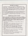
BEFORE YOU BEGIN
Congratulations
and thank you for selectingthe F660 HIP SLED strength
training system. The F660 HIP SLED offers an impressiveanay of strength
training exercisesto developevery major musclegroup of the body. Whether
your goal is cardiovascular
fitnessoa shapely,toned body or dramaticmuscle
size and strength,the F660 HIP SLED will help you achievethe specific
resultsyou want.
For your safety and benefit, read this manual and the accompanyingliterature
beforeusing the F660 HIP SLED. Keepthis manualfor futurereference.
If you haveadditionalquestions,
pleasecall your local dealeror our customer
service departmentat 800-990-5556
MondaythroughFriday,9a.m.until 5 p.m.
EasternTime.
IMPORTANT SAFETY NOTES
There is a risk assumedby individualswho use this fype of equipment.
Before beginningthis or any other exerciseprogram consult your physician.
This is especiallyimportant for individualsover the age of 35 or persons
with pre-existinghealth problems.RecreationSupply, Inc. assumesno
responsibilityfor personalinjury or properfy damagesustainedby or
through use of this product.
1. This productmust be assembledon a flat, level surfaceto assureits
proper function.
2. Cleanpads and frame on a regularbasis. We recommendwann,
soapywater. Do not use harsh or abrasivechemicals.
3. Inspectand tighten all parts before every use. Replaceany worx
parts immediately.Failure to do so may result in seriousinjury.
4. Keep children away from the F660 HIP SLED at all times.
5. Keep your handsaway from cablesand pulleys during operation.
Keep your hands away from moving parts other than the designated
handles.
6. When adjustingthe seat,make sure the spring pin is fully engaged.
If not, the seatmay slip and causeseriousinjury.
7. Exercisewith care to avoid inju.y.
8. If unsureabout the proper use of the F660 HIP SLED strength
training systemcall your local dealeror our customer
servicedepartment
at 800-990-5556.
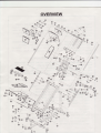
OVERVIEW
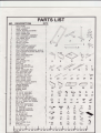
PARTSLIST
NO. DESCRIPTION
1
z
4
5
6
7
8
9
10
11
12
13
14
15
16
17
18
,o
20
21
22
23
24
25
26
27
t6
zv
30
?t
3Z
33
34
?A
?A
37
38
5:'
40
41
42
43
44
45
46
47
48
49
6n
41
3Z
54
58
5V
OU
61
62
64
67
QTY.
MAINFMME
FRONTSTABILIZER
REAR UPRIGHT
LINEARBEARINGASSEMBLY
S O L I DG U I D ER O D
BASE CONNECTOR
RIGHTSHOULDERASSEMBLY
LEFT SHOULDERASSEMBLY
LEG PRESS PLATE
1
FOOT PLATFORM
1
HIP PAD PLATE
1
WEIGHTHOLDER
z
CALF BLOCK
1
WEIGHTHOLDERSUPPORT
1
RIGHTSAFETYSTOPPER
I
LEFT SAFETYSTOPPER
ADJUSTERSLEEVE 1
FOOT PLATFORM
FOOTPLATFORM
ADJUSTER
INSIDETUBE 4
z
METALHINGE
1
FOOT PLATFORMAXLE
1
FOOT PLATEAXLE
PLA.STICCAP
H A N DG R I P
2
z
8 m m L O C K I N GP I N
z
S P R I N GC L I P
1
SEAT PAD
BACKAND HIP PAD
BACK SUPPORTERPAD
BACK PAD
RIGHTSHOULDERPAD
LEFT SHOULDERPAD
50X75mm ENDCAP
1
45x45mm SQ CAP
z
7 5 X 5 0 m mE N D P L U G
4
38mm ROUNDPLUG
2
3 1 m m R O U N DP L U G
25mm ROUNDPLUG
2
2
50 X 55mm PLASTICSLEEVE
1 / 2 "X 1 8 m mB U S H I N G
4
LINEARBEARING
4
R U B B E RB U M P E R
2
PLASTICSTUD
3
S P R I N GK N O B
4
POP PIN
112"X3-112',
HEX BOLT
2
1t2"X3-1t4" HEX BOLT
1
112"X3" HEX BOLT
1
5 / 1 6 " X 2 - 1 1 4H" E X B O L T
4
2
3t8"X2-3t4', HEX BOLT(ALL)
10
3 / 8 ' ' X1 ' ' I N N E RH E X S C R E W
?
3 1 8 " X 1 1 2I"N N E RH E X S C R E W
ALLEN BOLT
1
z
M8X 30mm DOME BOLT
5 / 1 6 " X1 / 4 ' 'S E T S C R E W
2
1/2" WASHER
21
3/8" WASHER(LARGER)
10
?
3/8" WASHER(SMALLER)
S P R I N GC L I P
4
4'7
1/2" NYLONNUT
3/8" NYLON NUT
4
5/16''SPRINGWASHER
4
6mm HEX KEY
1
3mm HEX KEY
1
FOAM TUBE
2
42mm ROUNDPLUG
z
NON SLIP
1
5 0 X 5 0 m mS O C A P
1
ltl
li
I]I
NT
|
{ l\ffi|
inch
112 sA
1t4 112 3t4
u*l,K
\
4
3*
:'w
-e\
qNAIN
INV'N7"
#"
89101112
4qffiXw n
z
A z//
19
20
\\26"
27
a
22
21
a
24
?
23
ffi-:
28
25
30
29
9aeAsoo
q"v
I
1t4
mm
U
31
32
33
Sogce@A
38
39
40
42
41
G-------FQOo@
45
49
53
57
c-------r-".0\
'46
54
50
SA
37
36
35
34
43
44
"61
65
64
67
wi,$F,s5
c-@Se
48
'tt4 112 3/4 3"
52
'tt4 112 3t44"
56
1t4 1t2 st4
60
.tt4 1t2 3/4 6"
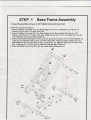
STEP 1 BaseFrameAssembly
Io ease fhe assembly process,do NOTtighten bolts until instructed.
Assemblyrequirestwo people.
(6)to the Boltsweldedon the FrontStabilizer
(2) usingtwo 1/2"
1.Attachthe BaseConnector
(55)
(59).
Washers
and two 112"NylonNuts
(6)to the Boltsweldedon the RearUpright(3) usingtwo 112"
2.Attachthe BaseConnector
Washers(55)andtwo 1l2"NylonNuts(59). Slidethetwo 50 X 75 mm EndCaps(32)ontothe
FrontStabilizer(2) andthe RearUpright(3).
3.Attachthe pre-assembled
MainFrame(1)to the verticalboltsweldedon the FrontStabilizer(2)
usingtwo 1/2"Washers(55)andtwo 1/2"NylonNuts(59).Attachthe RearUpright(3)to the
boltsweldedto thetop of the MainFrame(1)usingfiro ll2" Washers(55)and 1/2"NylonNuts
(59). Slidethetwo 75 X 50 mm EndCaps(34)ontothe MainFrame(1),
4, Slidethe 50X50mm Sq Cap(67)ontothe LinearBearing
Assembly(4).
59c
55@
59c
55
c59
o55
{a 5s
STEP 2
ShoulderPads,SafetyStoppers,
andWeightHolderAssembly
1.Attachthe WeightHolderSupport(14)to theWeightHolder(12)usingone112"X3-114"HexBolt
( 46),two 1/2"Washers(55),andone 1/2"NylonNut(59)on thetop holeof theWeightHolder
(12)and one112"X 3" HexBolt(47)at the bottomthreadedhole.
2.Attachthe WeightHolderAssembly
(12& 14)to the boltsweldedto the underside
of the Linear
Bearing
Assembly(4)andtightenwithfour1/2"Washers(55)andfour1/2"NylonNuts(59).
3. lnsertthe top endof the RightSafetyStopper(15)intothetop bracketon the MainFrame(1)and
thenslidethe bottomend intothe lowbracketon MainFrame(1), Checkto makesurethe Safety
Stopperrotatesand slidesfreely. Insertan 8mmLockingPin(24)intothe holeon the top of the
RightSafetyStopper(15). Tapthe LockingPinwitha hammerto makessureit is permanently
attached.Repeatthe procedure
for the LeftSafetyStopper(16).
4. Attachtwo 38mmRoundPlugs(35)to thetop on bothShoulderAssemblies
(7, 8).Attachone31
mm RoundPlug(36)to the handlesat thetop on bothShoulderAssemblies
(7,8).
5. Pullthe SpringKnob(43)on the rightsideof the LinearBearing
(4)
Assembly andinsertthe Right
(7).
(7)using
ShoulderAssembly Attachthe RightShoulder
Pad(30)to RightShoulderAssembly
two5/16"X2-114"HexBolts(48)andtwo 3/8"SmallWashers(57).Repeatthe sameprocedure
for the LeftShoulderAssembly
(8).
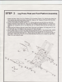
STEP 3
Leg PressPlateand FootPlatformAssembly
1.Attachthe bottomsideof the FootPlatform(10)to the MainFrame(1) by aligningthe holesand
theninserting
thesolidFootPlatform
Axle(20).Attacha 3/8"Washer(57)anda 3/8"Nut(60)
Axle(20).
to eachsideof the FootPlatform
AdjusterSleeve(17). Pullthe SpringKnob(43)andinsertthe Foot
2. Findthe FootPlatform
Platform
AdjusterInsideTulre(18).Attachthe FootPlatform
AdjusterSleeve(17)to the Front
(2),usingone112"X3-ll2 Bolt(45),two 112"Washers(55)and one1l2"NylonNut
Stabilizer
(5e).
(10)usingone 112"X33.Attachthe FootPlatform
AdjusterInsideTube(18)to the FootPlatform
112"Bolt(45),two 1/2"Washers(55),andone 1/2"NylonNut(59).
4. Attacha BackPad(27)to the Leg PressPlate(9) usingtwo 3/8"X 1" HexScrews(50). Attach
the LegPressPlate(9)to the LinearBearing
Assembly(4)by aligning
the holesandthen
inserting
the solidFootPlateAxle(21). Securewitha 3/8"Washer(57)anda 3/8"Nut(60)on
bothsides.Pullthe PopPin(44)on the LinearBearing
Assembly(4)to adjustthe LegPress
Plate(9)to yourdesiredangle.
v
60.
aa'
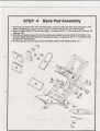
STEP 4
BackPadAssembly
1.Adjustthe LegPressPlate(9)to theflatposition
andthenattachthe BackPad(29)to the Linear
BearingAssembly(4) usingtwo 3/8"X2-314"HexBolts(49)andtwo 3/8"Washers(56),
2. Attachtwo BackPads(27)to Hip PadPlate(11)usingtwo 3/8"X 1" HexScrews(50)andtwo 3/8"
Washers(56).
3. Slidethetwo MetalHinges(19)ontothe smallaxlesweldedto thetop of the FootPlatform(10)
andthenattachthe BackPad(28)to the MetalHinges(19)usingtwo 3/8"X 1" HexScrews(50)
andtwo 3/8"Washers(56),
4. TheSpringClips(25)are usedto holdtheweightplateson theWeightHolder(12).
J
J
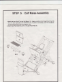
STEP5 GalfRaiseAssemblY
1,Attachthe NonSlip(67)to the CalfBlock(13),Attachone50mmEndPlug(33)andtwo 50
X 75 mm EndCaps(32)to the CalfBlock(13),Toperformcalfraises,inserttheCalfBlock
intothe centralholein the FootPlatform(10)'
2.AttachBackPadAssembly(27)to the LegPressPlate(9).
fi
N/
32
Assembly is complete! Please take the following steps before using the gym:
1. Make certain all bolts are tightened securely.
2.For better performance,apply a household lubricant (such as silicone) to any
adjustable areas and to the Linear BearingAssembly(4).
3. Enjoy many years of a Fit Lifestyle.
Thank you for purchasing the F660 HIP SLED. If You have any
questions, please call your local BodyCraft dealer or call our
customer service department at 800-990-5556