1
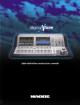
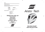
Warning
The auto-darkening filters fitted in the ORIGO™-TECH helmets are not waterproof and will not work properly if they have been in contact with water.
Welding helmets and filters only resist a certain amount of heat. Please do not place them near naked flames or hot work areas etc.
Operating temperature of electronic filter minus 5ºC to plus 55ºC.
Materials that may get in contact with the wearers skin could cause Allergic reactions to susceptible individuals
Certification and Control labels
The ORIGO™-TECH welding filters are tested for eye protection by the following notified body: DIN Prüf-und Zertifizierungsstelle für Augenschutz,
Alboinstr. 56, D-12103 Berlin, notified body 0196, that provides approval and continual quality system under the control of the European Commission,
the German Ministry for Work and the Central Office of the Provinces.
We are therefore allowed to use the following marks:
EN 175
European Conformity mark.
This confirms that the product fulfils the
requirements of the Directive 89/686/
EWG
Address from
DIN CERTCO Gesellschaft für Konformitätsbewertung mbH
Alboinstr. 56 ,
D-12103 Berlin
ADF Marking Explaination:
CE 4/9-13 ESAB 1/3/1/379
4 - light state scale number
9- lightest dark state scale number
13 darkest state scale number
ESAB - Manufactures identification
1 - Optical class
3 - Diffusion of light class
1 - variation in luminous transmittance class
379 - Number of the standard
ESAB Group (UK) Ltd
Hanover House
Queensgate,
Britannia Road,
Waltham Cross,
Hertfordshire EN8 7TF
England
www.esab.co.uk
ESAB AB operates a policy of continuous improvement. We therefore reserve the right to make changes and improvements to any of our products without notice.
Produced by Imergent Images Ltd. Tel: +44 (0) 1562 742273. E-mail: [email protected]
December 2008.
WELDING HELMET
USER INSTRUCTIONS
ORIGO™-TECH User Manual
ORIGO™-TECH:
Information manual for the ORIGO™-TECH welder protective helmets complying with Par. 1.4 of Appendix ll of the EC regulations. The ORIGO™-TECH welding helmets are high quality products that contribute
to the comfort and safety of the welder. ORIGO™-TECH welding helmets may be used only in connection with arc welding. The chart below shows how to choose the most suitable shade level:
To allow the filter to switch, both sensors on the front of the filter must not be covered. The filter then switches to the dark state when the arc strikes and to the clear state when it stops. The filter switches to
the light state when the welding arc stops.
Current internally in amperes
0.5
Welding process
Or related techniques
1
2.5
10
5
15
20
E manual
Flux core electrodes
Fluxed stick electrodes
30
40
60
80
100
10
9
MIG / Metal-Inert-Gas Argon (Ar/He)
Steels, alloyed steels,
Copper & its alloys etc.
10
9
MAG / Metal-active Gas(Ar/Co2O2) (Ar/Co2/He/H2)
Construction Steel, hardened & tempered steels
Cr-Ni-steel, Cr-steel & other alloyed steels.
175
200
10
4
6 7
1
0.5
5
2.5
10
9
8
15
10
30
20
60
40
80
13
14
13
12
200
175
The most suitable setting can be found on the Chart in this brochure or chosen
using your experience. This setting can also be made manually during the
welding process.
1
15
Turning clockwise
= darker
Turning anti clockwise = clearer
14
13
15
15
14
Before using the filter we recommend the following adjustments are made:
14
150
125
14
On the ORIGO™-TECH set the shade by turning the knob on the outside of
the helmet (pos. 1).
13
13
100
How to set the shade:
500
12
12
12
11
450
14
13
11
400
13
13
12
350
12
12
11
5
300
12
10
2.5
275
11
11
Plasma cutting (fusion cutting)
All weldable metals see WIG
Centre and outer gas: Argon (Ar/H2) (Ar/He)
250
11
Electric arc compressed air joining
(Melt joining) carbon electrodes (O2)
Flame grooving compressed air (O2)
Plasma cutting (Fusion cutting)
Micro-plasma welding
Centre and outer gas: Argon (Ar/H2) (Ar/He)
225
11
10
TIG / Tungsten-Inert Gas Argon (Ar/H2) (Ar/He)
All weldable metals such as: steels, aluminium,
Copper, nickel and their alloys.
150
11
10
MIG / Metal-Inert-Gas Argon (Ar/He)
Aluminium, copper, nickel
And other alloys.
125
15
Turn the sensitivity knob clockwise to the max. setting (pos. 2). Depending
upon the surrounding light the filter will switch to the dark state or will flicker
(if the surrounding light is very low, the filter may not switch to the dark state).
250
300
400
500
225
275
350
450
2
Depending upon the application conditions, the next highest or next lowest protection level can be used.
The darker fields correspond to those areas in which the corresponding welding process cannot be used.
Turn back the sensitivity knob (pos. 2) until the filter switches to the clear
state.
Information
Replacing the Outer Spatter Lens:
ORIGO™-TECH welding helmets afford reliable protection for the eyes whilst electric arc welding. They
offer permanent protection against UV/IR rays, heat & sparks in any state from the clear to dark. The
protection shades of the ORIGO™-TECH welding helmets have been chosen to avoid eye damage
caused by the welding arc.
Do not look directly at welding rays with unprotected eyes when the arc strikes. This can cause a painful
inflammation of the cornea and irreparable damage to the lens of the eye leading to catatacts.
ORIGO™-TECH welding helmets allow the welder to see the point of arc strike more precisely. This leads
to a real time saving. The helmet does not have to be flipped up and down during welding, both hands
are kept free and because of the helmets light weight fatigue is reduced.
Ensure that the helmet is always equipped with an Outside Lens (before the filter, on the outside of
the helmet) and an Inner Lens (behind the filter, inside the helmet). These protection lenses must be
replaced if broken, damaged or covered with welding spatter to such an extent that vision is impaired.
Inner & Outer Lenses are consumables and must be replaced regularly with certified ESAB
spare parts (CE marked).
Before using the ORIGO™-TECH helmet for the first time the protective films must be removed from
the Front Spatter Lens (drawing 1), The films cannot be removed from the Front Spatter Lens with
the Lens in place, Please follow the instructions below to remove the Spatter Lens.
Range of application:
LAN
All arc welding applications with the exception of TIG<20A and pulse inverter.
Available shade - 9-13 (pos.1).
0196
CE
HL:
D: Voor gebruik
Vor
F:
Gebrauc folie
verwijder
UK: Enlever
Before le filmh Schutzfo
I:
protecteu lie en!!
Prima use
entfernen
de’ll remove
r avant
uso
protectiv
!!
togliere
utilisatio
e coating!!
la protezion
e in
p
Setting the delay
The clearing delay can be adjusted manually by turning the delay knob (pos. 3) between a fast clear (0.1 sec) fully anti-clockwise and a
slow clear (1.0 sec) fully clockwise.
Drawing 1
➇
➆
Operation
➅
➃
➀
Adjustment of headgear:
ORIGO™-TECH welding helmets are equipped with a comfortable headgear that can be adjusted in
three different ways
➇
➄
Push and Turn“
Head size”
Turn
“Distance from face”
➂
➁
Spare parts for ORIGO™-TECH Welding Helmets
Items without a part number are not available as spare parts
No.
Push and Move
“Head Height”
“Rake adjustment”
Range of use for the ORIGO™-TECH:
1F DINplu
s GS
The ORIGO™-TECH welding helmets can be used for the following applications:
Electrode
MIG
Mag
Tig (>20A)
They are not suitable for use with laser systems and oxy-acetylene (gas welding) applications.The
welding filter must not be used for any other purpose other than welding. They should never be used
as sunglasses when driving as this could lead to incorrect identification of the colour of traffic light.
The welding filters operate well under extreme low lighting and very strong sunlight.
The filter is now set to its optimum sensitivity (According to the
surrounding light conditions).
Drawing 2
Inserting and removing a new protection lens:
To insert the new outer protection➃ lens the filter must be removed by unscrewing
the two retaining screws➇ from the inside of the helmet➀. The old protection lens
can then be removed and the new lens inserted followed by the light seal cradle➅,
ADF➆, inner protection lens➄ and then the ADF retaining frame➇ and finally
replace the two retaining screws (see drawing 2).
1
1
2
3
4
5
6
7
8
Part #
0700000296
0700000298
0700000243
0700000244
0700000245
0700000246
0700000235
0700000237
Description
Origo-Tech 9-13 Black
Origo-Tech 9-13 Yellow
Esab Head gear Pro
Sweat band head gear Pro
Front cover lens Origo-Tech
Inside cover lens Origo-Tech
ESAB 9-13 ADF cradle
ESAB VS ADF 9-13
Origo-Tech Lens retainer with screws
Filter Testing:
Servicing and maintenance
ORIGO™-TECH welding helmets should not be dropped. Do not place heavy objects or tools (hammers etc.) on or inside the helmet so as not to damage the electro-optical filter.
Always make sure that the helmet is equipped with an outside and inner lens (in front of the filter on the outside and on the inside behind the filter). These protection lenses must be replaced if damaged in any
way (see overleaf). They are consumables and should checked and replaced regularly.
The filter should be cleaned when changing the protection lenses.
This can be done by any of the following ways:
Wipe with a clean, dry piece of cloth.
Clean with a piece of smooth cloth moistened with pure alcohol.
Clean with a commercial disinfectant
If used properly the welding filter requires no further maintenance during its lifetime.
If a filter should be replaced on a ORIGO™-TECH welding helmet, use exclusively certified products
(DIN-CE marks). We recommend the use of ESAB welding filters in all ORIGO™-TECH helmets.
The filter itself contains no special or toxic products and can be disposed of in the same way as other electronic devices.
Before use of the welding helmet the auto darkening filter (ADF) and helmet needs to be checked according to the following procedure:
Check outer protection lens is clean and can be seen through.
Ensure the the sensors are covered in any way and are clean.
Once these checks have been carried out you can now test the ADF.
Turn the outside shade knob to the darkest setting (shade 13) and set the sensitivity to the highest setting (turning clockwise). Now point the sensor towards a light source such as an
overhead light, lamp etc. The ADF should now switch to the dark state (please note if the ADF is stored in a dark area away from light it may need to be left out in strong light for 20
minutes to absorb power, if after 20 minutes if the ADF does still not react then there is an issue with the sensor). Once the filter is in the dark state you can check the shade variation
is functioning correctly, simply turn the shade knob anti-clockwise. By doing this, the shade should get lighter. If the shade does not appear to alter then you have an issue with the
shade variation.
To test the delay function set the delay to the maximum setting. Now move the filter sensor away from the light source it should take 1 second to return to the light state, now alter the
delay setting to the minimum and repeat the process, the time taken to return to the clear state should be 0.1 second. If the ADF does not react in this way then there is an issue with
the delay function.
Testing the sensitivity. Set the sensitivity to minimum setting now point the ADF at the light source you used to test the other functions (if filter switches to dark state move away until
the filter returns to clear state) slowly turn the sensitivity clockwise until the filter switches to dark state (if it does not then move closer to the light until it reacts). If the ADF does not
react then there is an issue with the light sensors.
If any of the functions fail during test or in use then please do not use the ADF and contact your local distributor.
3