1
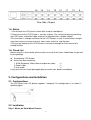
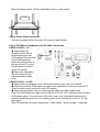
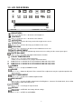
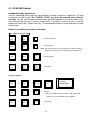
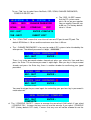
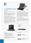
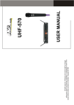
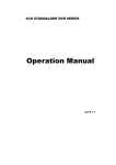
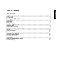
1U Rack LCD Drawer
LDS Series
User Guide
Rev. 2.2
This specification is subject to change without notice. Manufacturer assumes no responsibility
for any Error Contained herein.
IMPORTANT SAFETY INSTRUCTIONS
1. Please read these instructions carefully before using the product and save for later reference.
2. Follow all warnings and instructions marked on the product.
3. Unplug this product from the wall outlet before cleaning. Clean the product with a damp soft cloth. Do not
use liquid or aerosol cleaners as it may cause permanent damage to the screen.
4. Do not use this product near water.
5. Do not place this product on an unstable cart, stand, or table.
The product may fall, causing serious damage to the product.
6. Slots and openings in the cabinet and the back or bottom are provided for ventilation; to ensure reliable
operation of the product and to protect it from overheating, these openings must not be blocked or covered.
The openings should never be placed near or over a radiator or heat register, or in a built-in installation
unless proper ventilation is provided.
7. This product should be operated from the type of power indicated on the marking label.
of the type of power available, consult your dealer or local power company.
If you are not sure
8. This product is equipped with a 3-wire grounding type plug, a plug having a third (grounding) pin. This
plug will only fit into a grounding-type power outlet. This is a safety feature. If you are unable to insert the
plug into the outlet, contact your electrician to replace your obsolete outlet.
Do not defeat the purpose of the grounding-type plug.
9. Do not allow anything to rest on the power cord.
cord.
Do not locate this product where persons will walk on the
10. If an extension cord is used with this product, make sure that the total of the ampere ratings on the products
plugged into the extension cord does not exceed the extension cord ampere rating. Also make sure that
the total of all products plugged into the wall outlet does not exceed 15 amps.
11. Never push objects of any kind into this product through cabinet slots as they may touch dangerous voltage
points or short out parts that could result in a risk of fire or electric shock. Never spill liquid of any kind on
the product.
12. Do not attempt to service this product yourself, as opening or removing covers may expose you to
dangerous voltage points or other risks and will void the warranty. Refer all servicing to qualified service
personnel.
13. Unplug this product from the wall outlet and refer servicing to qualified service personnel under the
following conditions:
a. When the power cord or plug is damaged or frayed.
b. If liquid has been spilled into the product.
c. If the product has been exposed to rain or water.
d. If the product does not operate normally when the operating instructions are followed. Adjust only
those controls that are covered by the operating instructions since improper adjustment of other
controls may result in damage and will often require extensive work by a qualified technician to restore
the product to normal operation.
e. If the product has been dropped or the cabinet has been damaged.
f. If the product exhibits a distinct change in performance, indicating a need for service.
2
Contents
1. Introduction.......................................................................................................................................... 4
1.1. Overview................................................................................................................................... 4
1.2. Major Features .......................................................................................................................... 4
1.3. Outline Drawing ....................................................................................................................... 4
1.4. Notice........................................................................................................................................ 5
1.5. Check List ................................................................................................................................. 5
2. Configurations and Installation............................................................................................................ 5
2.1. Configurations .......................................................................................................................... 5
2.2. Installation ................................................................................................................................ 5
3. LCD OSD Key Definition ................................................................................................................... 7
3.1. The Control Key Description.................................................................................................... 7
3.2. LCD OSD SCREEN ................................................................................................................. 8
4. KVM (optional) ................................................................................................................................... 9
4.1. KVM OSD Control................................................................................................................. 10
4.2 KVM ON SCREEN DISPLAY OPERATION ........................................................................ 12
5. Specifications..................................................................................................................................... 14
6. Cleaning the Rack Drawer Monitor................................................................................................... 15
7. Disclaimer.......................................................................................................................................... 15
8. Troubleshooting: ................................................................................................................................ 15
9. Appendix:........................................................................................................................................... 16
9.1 Supporting Resolution Modes: ................................................................................................ 16
9.2. Limited Warranty.................................................................................................................... 17
3
1. Introduction
1.1. Overview
The LDS series (LDS210D/LDS310D/LDS410D) are a series of compact devices, built-in a
15”, 17” or 19” LCD display, standard keyboard with numerical keypad, and heavy-duty
touch pad to eliminate hardware redundancy and to increase cost efficiency. The 1U rack
mount is designed to be an ideal solution for saving valuable rack mounting space, while
possessing features such as monitor flip up design, adjustable mounting brackets, built-in
LCD OSD and an optional centralized control of 8/16 PCs.
1.2. Major Features
Item
TFT Display
OSD Function
VGA
DVI(optional)
Power Consumption(Watts)
Power Supply
Keyboard and Touch Pad
Numerical Key Pad
Dimensions
Operating Temperature
KVM Switch (optional)
LDS210D
LDS310D
LDS410D
15”
17”
19”
Built in OSD Screen Adjustment Function
15-pin D-sub RGB Analog Input Signal
DVI-D
None
None
33
38
41
AC 100-240V Universal
88-key Keyboard and Integrated Touch Pad
17-key numerical Key Pad
1U compact design, 517mm (D) x484mm (W) x44mm (H)
0° to 50° C Operating Temperature
OSD controlled 8/16 port KVM switch
1.3. Outline Drawing
Front Side
Mounted on Rack-Mount Chassis
Rear Side (1 port)
4
16
15
14
13
12
11
10
9
8
7
6
5
Rear Side (16 port)
4
3
2
1
1.4. Notice
1. Do not touch the LCD panel surface with sharp or hard objects.
2. Please ensure the LCD Drawer is securely in place. The surface for placing and fixing
the LCD Drawer should be stable and level or mounted into a suitable cabinet.
3. Ensure there is enough ventilation for the LCD Drawer, as well as out of direct sunlight,
away from sources of excessive dust, heat, water, moisture, and vibration.
4. Ensure the location of the LCD Drawer is convenient enough for it to connect to its
related facilities.
1.5. Check List
Before using this rack monitor, please make sure that all the items listed below are present
in your package
Analog color LCD Drawer
Accessory Box containing:
1. KVM (Keyboard, Video, Mouse) expansion cable
×1
2. Power cable
×1
3. User guide
×1
If any items are missing or damaged, please contact your dealer immediately.
2. Configurations and Installation
2.1. Configurations
The LDS serials rack LCD drawer supports 1 computer. The configuration is as shown in
following figure.
2.2. Installation
Step 1. Mount on Rack-Mount Chassis
5
Mount the Rack Drawer LCD on Rack-Mount Chassis with screws.
STEP1
Step 2. Power Cable Connection
Connect the power cord to the rack LCD monitor and AC outlet.
Step 3. PS2 Mouse, Keyboard and VGA Cable Connection
LDS210/310/410 – 1P:
◆ Power down the
computer which will be
connected to your rack
LCD monitor. Plug one end
Cable Appearance
of the KVM expansion
cable to the connectors at
the rear of the PC system
and the other end to the
rack LCD monitor.
◆ Secure the connectors
with the screws on the
cable connector at both
ends.
LDS210/310/410 – 8/16P:
◆ Power down all computers which will be connected to your rack LCD monitor.
◆ Plug one end of the KVM expansion cable to the connectors at the rear of all the PC
systems and the other end to the rack LCD monitor.
◆ Secure the connectors with the screws on the cable connector at both ends
Note: The KVM expansion cable for the LDS210/ 310/ 410 -16P is different from the other
KVM switch cables. The end of the KVM switch side is the 15-pin black connector for
monitor, keyboard and mouse. The matching port of the KVM switch also uses 15 –pin
black ports.
Note: All connectors are color coded; blue – video, green – mouse, purple – keyboard
6
Cable Appearance
ONE OF YOUR
COMPUTER
LDS210/310/410-16P
3. LCD OSD Key Definition
1. MENU
Use this key to select the function you would like to adjust.
2. ADJUST
Use this key to adjust the selected function for optimal viewing.
3. POWER SWITCH
Use the power switch to turn the power ON or OFF.
then the LCD monitor.
We recommend turning your PC system power on first,
4. POWER STAND-BY MODE LED
Indicates when the power is in the stand-by mode.
5. Power on LED
Indicates when the power is in the ON position.
3.1. The Control Key Description
+
: Power on/off control.
: Call menu / Shifting the selection left.
: Call menu / Shifting the selection right.
: Decrease value.
: Increase value. / Automatic adjustment.
7
3.2. LCD OSD SCREEN
-
+
100
0
1024x768
H:60.09KHz V:75.12Hz
BRIGHTNESS
Press "+" to increase or "-" to decrease the brightness.
CONTRAST
Press "+" to increase or "-" to decrease the contrast.
H-POSITION
Press "+" or "-" to move the image to the left or right on the screen.
V-POSITION
Press "+" or "-" to move the image up or down on the screen.
H-SCALING
Press "+" or "-" to increase or decrease the Horizontal screen size.
AUTO ADJUSTMENT
Press "+" or "-" to have the monitor logic choose the best settings for the current input signal.
WHITE BALANCE
Press "+" or "-" to enable auto adjust white balance function.
COLOR TEMPERATURE
Press "+" or "-" to set the color temperature
USER: Use this function to set a proper color temperature.
9300K:Push to set monitor for the CIE coordinate 9300 color temperature
6500K:Push to set monitor for the CIE coordinate 6500 color temperature
5500K:Push to set monitor for the CIE coordinate 5500 color temperature
GAMMA
Press "+" or "-" to adjust GAMMA Function.
PHASE
Press "+" or "-" button to adjust the Phase control. Phase adjustment may be required to optimize the
display quality.
OSD TRANSPARENT
Press "+" or "-" to adjust the OSD background color.
ADC ADJUST
Press "+" or "-" to enter the ADC control manual for Brightness, Contrast, Red Color Gain, Green Color
Gain and Blue Color Gain adjustment.
CHANNEL
Press "+" or "-" to change the input channel
RECALL
Press "+" or "-" to RECALL the factory default settings.
OSD EXIT
Press "+" or "-" to EXIT the OSD MENU.
8
Summary
BRIGHTNESS: Press "+" or "-" to adjust.
CONTRAST: Press "+" or "-" to adjust.
H-POSITION: Move the screen to the left or right side.
V-POSITION: Move the screen up or down.
CLOCK: To adjust the Horizontal screen size.
AUTO: To find the optimal screen settings.
WHITE BALANCE: White Balance value adjust.
COLOR TEMPERATURE: Color Temperature settings.
GAMMA: Gamma value adjust.
PHASE: Adjust horizontal phase for optimal display quality.
TRANSPARENT: OSD Transparent adjustment.
ADC CONTROL: Color degree adjustment.
CHANNEL: change the input channel
RECALL: Press "+" or "-" to reset the factory default settings.
EXIT: To exit from the OSD function.
4. KVM (optional)
The 1U Rack LCD Drawer build-in KVM Switch enables a single keyboard, video monitor and
mouse to control multiple computers at a time. This product supports one console and 8/16
computer ports. Product model number as follow table:
LDS210D-8P
LCD
Size
15”
LDS310D-8P
17”
8
LDS410D-8P
19”
8
LDS210D-16P
15”
16
LDS310D-16P
17”
16
LDS410D-16P
19”
16
P/N
Computer port number
8
This series KVM switch has an On-screen Display (OSD) menu so that you can operate the
system easily.
9
4.1. KVM OSD Control
Keyboard Hot Key Commands:
You can command KVM switch by switching ports through simple key sequences. To send
commands to KVM switch, the “SCROLL LOCK” key must be pressed twice within 2
seconds. You will hear a beep for confirmation and the keyboard is in hot key mode. If you
have not pressed any key in hot key mode within 2 seconds (It means to key in any key
follows up “Scroll Lock” “Scroll Lock” key ), the keyboard will back to under Operation System
control state.
Below are the different hot key commands:
within 2 seconds
Scroll
Lock
+
Scroll
Lock
+
↑
=
Previous Channel
Scroll
Lock
+
Scroll
Lock
+
↓
=
Next Channel
(Note: You also could press “up arrow key” or “down arrow key”
longer time to speed up selecting the destination port)
Scroll
Lock
+
Scroll
Lock
Scroll
Lock
+
Scroll
Lock
+
+
Page
Up
Page
Down
=
=
Previous Bank
Next Bank
To select PC port:
Scroll
Lock
Scroll
Lock
+
+
Scroll
Lock
Scroll
Lock
+
+
Bank
No 1~8
B
Port No
0 or 1
=
Port No.
1~8 (8 port)
1~16 (16 port)
Beeper
(Note: The default Beeper function is ON and beeper
control is only for available for Scan Mode )
Scroll
Lock
+
Scroll
Lock
+
S
=
Auto Scan
10
To get out of Auto Scan Mode, Press any key or SPACE bar.
Scroll
Lock
+
Scroll
Lock
+
=
R
OSD setting back to factory default value
(Note: Not including password)
ROM
Scroll
Lock
+
Scroll
Lock
F
+
=
REFLASH
Search the same PC name
st
(Note: Search PC name starting from 1 PC port)
FIND:█
Scroll
Lock
+
Scroll
Lock
+
Space bar
=
On Screen Display Menu
:
Example
A. To access a computer attached to Port 4 of the three Bank. You can press through hot key as below:
Scroll lock + Scroll lock + 3 + 04
B. To access a computer attached from Bank 3 to Bank 4, You can press through hot key as below:
Scroll lock + Scroll lock + Page Down
Note:
Bank no. and Port no. selection must be made using the numeric keys on the keyboard.
Numeric keys on the keypad are not available as a hot key command.
11
4.2 KVM ON SCREEN DISPLAY OPERATION
1. OSD menu can be popped up in powered on PC port or non-powered on PC port or empty
PC port. The resolution of OSD menu is fixed to 1024X768 for non-powered on PC port or
empty PC port.
2. When you pop up the OSD menu window go through the hot key, you will see the following
small window on your monitor.
BANK : 1
a. The 1ST line bar is Bank no.
SYSTEM
01
02 ☼SYSTEM
02 03 ☼SYSTEM
03
04 ☼SYSTEM
04
05 ☼SYSTEM
05
06
SYSTEM
06
07
SYSTEM
07
08 ☼SYSTEM
08
09
SYSTEM
09
10
11 ☼SYSTEM
11
10 SYSTEM
1
12 ☼SYSTEM
13
SYSTEM
13
14 ☼SYSTEM
14
15 ☼SYSTEM
15
16
16
01
OSD : 1 0 SEC.
SYSTEM
12
CHANGE PASSWORD
SCAN: 1 0 SEC.
CONSOLE ON/OFF
ESC : QUIT
ENTER :COMPLETE
TAB : NEXT
INSERT :EDIT
b. The 2nd block is your PC
system name list. You will find
the system number list from 01
to 04 ( if the current box is 4 port)
or from 01 to 8 (if the current
box no. is 8 port)or from 01 to 16
(if the current box no. is 16 port).
You can define your PC name in
maximum 8 characters. The
factory default of 16 port KVM
switch PC name is from
“SYSTEM 01”, “SYSTEM 02” ,…,
“SYSTEM 16” and 8 port KVM
switch is from “SYSTEM 01”,
“SYSTEM 02”,…, “SYSTEM 08”.
Besides, the sun symbol “ ☼
“ near to the PC name
represents the PC system is
powered on.
/
: PORT SELECT
PgDn/PgUp: BANK
SELECT
To use up arrow key “ “ or down arrow key “ “ to select port for destination PC
name. After you have selected the PC port already, you can press the ENTER Key to
switch the PC port you want immediately
To use “ PgUp “ key or “ PgDn” key for selecting previous or next Bank no. (or Box No.)
BANK : 1
01
SYSTEM
01
02 ☼SYS█EM
02 To press “ INS” key for editing
PC name.
After finishing the edit, please press “Enter “key for saving information.
12
To use “ Tab “ key to select items like Bank, OSD, SCAN, CHANGE PASSWORD,
CONSOLE ON/OFF, etc…
15
15☼SYSTEM
15
16
SYSTEM
16
OSD : 1 0 SEC. CHANGE PASSWORD
SCAN: 1 0 SEC.
CONSOLE ON/OFF
ESC : QUIT
ENTER :COMPLETE
TAB : NEXT
INSERT :EDIT
a. The “OSD: 10 SEC” means
that the PC system name
exists 10 sec on your monitor.
You can modify it from 05 sec
to 99 sec. The factory default
value is 10 sec.
b. The “ SCAN TIME” means that scan interval from one PC port to next PC port. The
default SCAN time is 10 sec and the maximum scan time is 99 sec.
c. The “ CHANGE PASSWORD” is for user to avoid all PC systems to be intruded by the
other person. The default password is 8 digits “ 00000000 “.
ENTER
PASSWORD : █
ESC : QUIT
ENTER :
COMPLETE
There is an enter
password window showed out when you select this item and then
press the Enter. The maximum password is eight digits. After you key in the password
already and press the Enter key, there is another window for confirming your typed
password.
ENTER
NEW
PASSWORD : █
ESC : QUIT
ENTER :
COMPLETE
RETYPE NEW PASSWORD : █
COMPLETE
ESC : QUIT
ENTER :
COMPLETE
You need to retype the password again for rechecking your previous key-in password is
matched or not.
NEW
PASSWORD
ESC : QUIT
COMPLETE
COMPLETE
ENTER :
d. The “ CONSOLE ON/OFF “ means to manage the console of KVM switch. If you select
“ CONSOLE ON “, it means that any user can use the console. If you select “ CONSOLE
OFF “(factory default OFF state), it means that any user will not be allowed to use the
13
console unless you enter the password. When you enter the password already and pass
the KVM switch authentication, the CONSOLE will be set to ON. After you finish using
KVM switch, please don’t forget to set up CONSOLE ON state to OFF state. Besides, if
current CONSOLE is ON state and you reset KVM switch, the CONSOLE will be set up
ON state back to OFF state.
e. When you finish the set up of PC name and get out of OSD setting mode, you will find the
PC name showed at the up-left corner of monitor. Now, you can use ESC key to clear the
message right away if you don’t need it.
102
☼SYSTEM
02
f. If you want OSD returning back to factory default value, you can execute “SCROLL
LOCK”, “SCROLL LOCK” , “R” keys in order. The bank seven segment LED on the front
panel will be flashed during the refresh process.
ROM
REFLASH
When the OSD value back to default setting, the bank seven segment LED on the front
panel will stop flashing
5. Specifications
Item
LDS210D
LDS310D
LDS410D
Display Area(mm) 304.1(H) x 228.1(V)
337.9(H) x 270.3(V)
376.3(H) x 301.1(V)
(15-inch diagonal)
(17-inch diagonal)
(19-inch diagonal)
Pixel Pitch
0.297(H) x 0.297(V)
0.264(H) x 0.264(V)
0.294(H) x 0. 294(V)
Number of Pixels 1024(H) x 768(V)
1280(H) x 1024(V)
1280(H) x 1024(V)
Contrast Ratio
350:1
800:1
800:1
Display Color
16.2M colors
16.7M colors
16.7M colors
Brightness
250
300
300
(CD/m^2)
Backlight Unit
2 replaceable CCFLs 4 replaceable CCFLs edge-light (top/bottom)
edge-light (top/bottom)
Viewing Angle
-65º~65º(H),
-70º~70º(H),
-85º~85º(H),
-50º~55º(V)(Typ.)
-60º~60º(V) (Typ.)
-85º~85º(V) (Typ.)
I/O
Power: 12V DC Adapter
Keyboard:PS/2
Mouse:PS/2
VGA:15-pin D-sub
Keyboard
88-key keyboard and integrated Touch Pad
and Key pad
17-key numerical key pad
Power
33 Watts
38 Watts
41 Watts
Consumption
Power Supply
AC 100-240V Universal
On-Screen Display Contrast, Brightness, H/V Position, H/V Size, H-scaling, Auto-adjust,
Color Temp.(9300, 6500, User), Red-Gain, Blue-Gain, Green-Gain,
Gamma, Recall, Phase, OSD & Exit
Hot Key Control
OSD Hot Key
Environmental
Operating temperature:0ºC~ 50ºC (32 F~ 122 F)
consideration
Storage temperature:-20ºC~ 60ºC(-4 F~ 140 F)
Humidity
10~85% in operating; 10-90% in storage
14
Size
517mm(D) x 484mm(W) x 44mm(H)
6. Cleaning the Rack Drawer Monitor
Make sure the rack drawer monitor is turned off.
Never spray or pour any liquid directly onto the screen or case.
Wipe the screen with a clean, soft, lint-free cloth. This removes dust and other particles.
The display area is highly prone to scratching. Do not use ketene type material (ex.
Acetone), Ethyl alcohol, toluene, ethyl acid or Methyl chloride to clear the panel. It might
permanently damage the panel.
If still not clean, apply a small amount of non-ammonia, non-alcohol based glass cleaner
onto a clean, soft, lint-free cloth, and wipe the screen
Don't let water or oil penetrate the monitor. If the droplets are kept for a long time,
Staining and discoloration may occur.
7. Disclaimer
We do not recommend the use of any ammonia or alcohol-based cleaners on the
monitor screen or case. Some chemical cleaners have been reported to damage the screen
and/or case of the rack LCD monitor. Seller will not be liable for damage resulting from use
of any ammonia or alcohol-based cleaner.
8. Troubleshooting:
Ensure that all cables are well seated. Check that keyboard/mouse cables are not
swapped. If your monitor fails to operate correctly, consult the following chart for possible
solution before calling for repairs:
Condition
Check Point
1. The picture does not
Check if the signal cable is firmly seated in the socket.
appear
Check if the Power is ON at the computer
Check if the brightness control is at the appropriate
position, not at the minimum.
2. The screen is not
Check if the signal cable is firmly seated in the socket.
synchronized
Check if the output level matches the input level of your
computer.
Make sure the signal timings of the computer system are
within the specification of the monitor.
If your computer was working with a CRT monitor, you
should check the current signal timing and turn off your
computer before you connect the VGA Cable to this
monitor.
3. The position of the screen Adjust the H-position, and V-position, or Perform the Auto
is not in the center
adjustment.
15
4. The screen is too bright
(too dark).
Check if the brightness or contrast control is at the
appropriate position, not at the Maximum (Minimum).
5. The screen is shaking or
waving
Press ”+” (the Auto - adjustment control) to adjust.
Moving all of objects which emit a magnetic field such as
motor or transformer, away from the monitor. Check if the
specific voltage is applied.
Check if the signal timing of the computer system is within
the specification of monitor.
6. Mouse or Keyboard is not Verify that the mouse or keyboard is correctly plugged in to
functioning
the KVM switch.
(for LDS 210/310/410-8/16P)
Verify that the cable is correctly connected between the
computer and the KVM switch.
Restart the computers.
Verify that the keyboard or mouse works when connected
directly to the computer.
Note: The mouse will be inactive when OSD menu is active.
7. Hotkey selection is not
The Hotkey or Push button selection is inactive when the
functioning
password is active.
If you are unable to correct the fault by using this chart, stop using your monitor and
contact your distributor or dealer for further assistance.
9. Appendix:
9.1 Supporting Resolution Modes:
LDS210D(15”):
Mode
Mode 1
Mode 2
Mode 3
Mode 4
Mode 5
Mode 6
Mode 7
Mode 8
Mode 9
Mode 10
Mode 11
Mode 12
Mode 13
Resolution
640×350
640×400
640×480
640×480
640×480
720×400
800×600
800×600
800×600
800×600
1024×768
1024×768
1024×768
LDS310D(17”)/LDS410D(19”):
H-Freq. (KHz)
31.5
31.5
31.5
37.9
37.5
31.5
35.1
37.9
48.1
46.9
48.4
56.5
60.0
V-Freq. (KHz)
70
70
60
72
75
70
56
60
72
75
60
70
75
Mode
Mode 1
Mode 2
Mode 3
Mode 4
Mode 5
Mode 6
Mode 7
Mode 8
Mode 9
Mode 10
Mode 11
Mode 12
Mode 13
Mode 14
Mode 15
16
Resolution
640×350
640×400
640×480
640×480
640×480
720×400
800×600
800×600
800×600
800×600
1024×768
1024×768
1024×768
1280×1024
1280×1024
H-Freq.(KHz) V-Freq.(KHz)
70
31.5
70
31.5
60
31.5
72
37.9
75
37.5
70
31.47
56
35.1
60
37.9
72
48.1
75
46.9
60
48.4
70
56.5
75
60.0
60
64.0
80.0
75
9.2. Limited Warranty
In no event shall the direct vender’s liability for direct or indirect, special, incidental or
consequential damages, loss of profit, loss of business, or financial loss which may be
caused by the use of the product exceeds the price paid for the product.
The direct vendor makes no warranty or representation, expressed or implied with
respect to the contents or use of this documentation, and especially disclaims its quality,
performance, merchantability, or fitness for any particular purpose.
The direct vendor also reserves the right to revise or update the product or
documentation without obligation to notify any user of such revisions or updates. For
further information, please contact your direct vendor.
All the brand names and registered trademarks are the property of their respective
owners.
17