1
User Manual
UBC-221
Industrial Internet of Things
Gateway
Copyright
The documentation and the software included with this product are copyrighted 2015
by Advantech Co., Ltd. All rights are reserved. Advantech Co., Ltd. reserves the right
to make improvements in the products described in this manual at any time without
notice. No part of this manual may be reproduced, copied, translated or transmitted
in any form or by any means without the prior written permission of Advantech Co.,
Ltd. Information provided in this manual is intended to be accurate and reliable. However, Advantech Co., Ltd. assumes no responsibility for its use, nor for any infringements of the rights of third parties, which may result from its use.
Acknowledgements
Intel is trademark of Intel Corporation.
All other product names or trademarks are properties of their respective owners.
For more information about this and other Advantech products, please visit our website at:
http://www.advantech.com/
http://www.advantech.com/ePlatform/
For technical support and service, please visit our support website at:
http://support.advantech.com.tw/support/
UBC-221 User Manual
Part No. 2006U22100
Edition 1
Printed in Taiwan
June 2015
ii
Product Warranty (2 years)
Advantech warrants to you, the original purchaser, that each of its products will be
free from defects in materials and workmanship for two years from the date of purchase.
This warranty does not apply to any products which have been repaired or altered by
persons other than repair personnel authorized by Advantech, or which have been
subject to misuse, abuse, accident or improper installation. Advantech assumes no
liability under the terms of this warranty as a consequence of such events.
Because of Advantech’s high quality-control standards and rigorous testing, most of
our customers never need to use our repair service. If an Advantech product is defective, it will be repaired or replaced at no charge during the warranty period. For outof-warranty repairs, you will be billed according to the cost of replacement materials,
service time and freight. Please consult your dealer for more details.
If you think you have a defective product, follow these steps:
1. Collect all the information about the problem encountered. (For example, CPU
speed, Advantech products used, other hardware and software used, etc.) Note
anything abnormal and list any onscreen messages you get when the problem
occurs.
2. Call your dealer and describe the problem. Please have your manual, product,
and any helpful information readily available.
3. If your product is diagnosed as defective, obtain an RMA (return merchandize
authorization) number from your dealer. This allows us to process your return
more quickly.
4. Carefully pack the defective product, a fully-completed Repair and Replacement
Order Card and a photocopy proof of purchase date (such as your sales receipt)
in a shippable container. A product returned without proof of the purchase date
is not eligible for warranty service.
5. Write the RMA number visibly on the outside of the package and ship it prepaid
to your dealer.
iii
UBC-221 User Manual
Declaration of Conformity
FCC Class B
Note: This equipment has been tested and found to comply with the limits for a Class
B digital device, pursuant to part 15 of the FCC Rules. These limits are designed to
provide reasonable protection against harmful interference in a residential installation. This equipment generates, uses and can radiate radio frequency energy and, if
not installed and used in accordance with the instructions, may cause harmful interference to radio communications. However, there is no guarantee that interference
will not occur in a particular installation. If this equipment does cause harmful interference to radio or television reception, which can be determined by turning the equipment off and on, the user is encouraged to try to correct the interference by one or
more of the following measures:
Reorient or relocate the receiving antenna.
Increase the separation between the equipment and receiver.
Connect the equipment into an outlet on a circuit different from that to which the
receiver is connected.
Consult the dealer or an experienced radio/TV technician for help.
Technical Support and Assistance
1.
2.
Visit the Advantech website at http://support.advantech.com where you can find
the latest information about the product.
Contact your distributor, sales representative, or Advantech's customer service
center for technical support if you need additional assistance. Please have the
following information ready before you call:
– Product name and serial number
– Description of your peripheral attachments
– Description of your software (operating system, version, application software,
etc.)
– A complete description of the problem
– The exact wording of any error messages
UBC-221 User Manual
iv
Warnings, Cautions and Notes
Warning! Warnings indicate conditions, which if not observed, can cause personal
injury!
Caution! Cautions are included to help you avoid damaging hardware or losing
data. e.g.
There is a danger of a new battery exploding if it is incorrectly installed.
Do not attempt to recharge, force open, or heat the battery. Replace the
battery only with the same or equivalent type recommended by the manufacturer. Discard used batteries according to the manufacturer's
instructions.
Note!
Notes provide optional additional information.
Packing List
Before setting up the system, check that the items listed below are included and in
good condition. If any item does not accord with the table, please contact your
dealer immediately.
1x UBC-221 unit with Wall mount bracket
2x Female connectors for terminal block.
Ordering Information
Model Number
Description
UBC-221CS-GNA1E
Intel Quark x1000 400MHz w/ PoE
Optional Accessories
Model Number
Description
96PSA-A36W12R1
Adaptor 100-240V 36W 12V 3A
1700001524
3-pin USA standard power cord
170203183C
3-pin Europe standard cord
170203180A
3-pin UK standard power cord.
v
UBC-221 User Manual
Safety Instructions
1.
2.
3.
Read these safety instructions carefully.
Keep this User Manual for later reference.
Disconnect this equipment from any AC outlet before cleaning. Use a damp
cloth. Do not use liquid or spray detergents for cleaning.
4. For plug-in equipment, the power outlet socket must be located near the equipment and must be easily accessible.
5. Keep this equipment away from humidity.
6. Put this equipment on a reliable surface during installation. Dropping it or letting
it fall may cause damage.
7. The openings on the enclosure are for air convection. Protect the equipment
from overheating. DO NOT COVER THE OPENINGS.
8. Make sure the voltage of the power source is correct before connecting the
equipment to the power outlet.
9. Position the power cord so that people cannot step on it. Do not place anything
over the power cord.
10. All cautions and warnings on the equipment should be noted.
11. If the equipment is not used for a long time, disconnect it from the power source
to avoid damage by transient overvoltage.
12. Never pour any liquid into an opening. This may cause fire or electrical shock.
13. Never open the equipment. For safety reasons, the equipment should be
opened only by qualified service personnel.
14. If one of the following situations arises, get the equipment checked by service
personnel:
The power cord or plug is damaged.
Liquid has penetrated into the equipment.
The equipment has been exposed to moisture.
The equipment does not work well, or you cannot get it to work according to
the user's manual.
The equipment has been dropped and damaged.
The equipment has obvious signs of breakage.
15. DO NOT LEAVE THIS EQUIPMENT IN AN ENVIRONMENT WHERE THE
STORAGE TEMPERATURE MAY GO BELOW -20° C (-4° F) OR ABOVE 60° C
(140° F). THIS COULD DAMAGE THE EQUIPMENT. THE EQUIPMENT
SHOULD BE IN A CONTROLLED ENVIRONMENT.
16. CAUTION: DANGER OF EXPLOSION IF BATTERY IS INCORRECTLY
REPLACED. REPLACE ONLY WITH THE SAME OR EQUIVALENT TYPE
RECOMMENDED BY THE MANUFACTURER, DISCARD USED BATTERIES
ACCORDING TO THE MANUFACTURER'S INSTRUCTIONS.
The sound pressure level at the operator's position according to IEC 704-1:1982 is
no more than 70 dB (A).
DISCLAIMER: This set of instructions is given according to IEC 704-1. Advantech
disclaims all responsibility for the accuracy of any statements contained herein.
UBC-221 User Manual
vi
Safety Precaution - Static Electricity
Follow these simple precautions to protect yourself from harm and the products from
damage.
To avoid electrical shock, always disconnect the power from your PC chassis
before you work on it. Don't touch any components on the CPU card or other
cards while the PC is on.
Disconnect power before making any configuration changes. The sudden rush
of power as you connect a jumper or install a card may damage sensitive electronic components.
vii
UBC-221 User Manual
UBC-221 User Manual
viii
Contents
Chapter
1
General Introduction ...........................1
1.1
1.2
Introduction ............................................................................................... 2
Product Features....................................................................................... 2
1.2.1 Key Features................................................................................. 2
1.2.2 General ......................................................................................... 2
1.2.3 Ethernet ........................................................................................ 2
1.2.4 Power Consumption...................................................................... 3
Mechanical Specification........................................................................... 3
1.3.1 Dimensions ................................................................................... 3
1.3.2 Weight........................................................................................... 3
Power Requirements................................................................................. 3
1.4.1 System Power............................................................................... 3
1.4.2 RTC Battery .................................................................................. 3
Environment Specifications....................................................................... 4
1.5.1 Operating Temperature................................................................. 4
1.5.2 Relative Humidity .......................................................................... 4
1.5.3 Storage Temperature.................................................................... 4
1.5.4 Vibration Loading during Operation .............................................. 4
1.5.5 EMC .............................................................................................. 4
1.3
1.4
1.5
Chapter
2
Hardware Functionality .......................5
2.1
2.2
Introduction ............................................................................................... 6
UBC-221 I/O Indication ............................................................................. 6
Figure 2.1 UBC-221 front view .................................................... 6
Figure 2.2 UBC-221 LED indication............................................. 6
Figure 2.3 UBC-221 left side view ............................................... 6
UBC-221 I/O Connectors .......................................................................... 7
2.3.1 Power Input Connector ................................................................. 7
Figure 2.4 Power input connector................................................ 7
2.3.2 COM Connector ............................................................................ 7
Figure 2.5 COM connector .......................................................... 7
Table 2.1: COM Connector Pin Assignment................................ 7
2.3.3 Ethernet Connector (LAN) ............................................................ 8
Figure 2.6 Ethernet connector ..................................................... 8
2.3.4 USB Connector ............................................................................. 8
Figure 2.7 USB connector ........................................................... 8
2.3.5 GPIO Connector ........................................................................... 8
Figure 2.8 GPIO connector.......................................................... 8
Table 2.2: GPIO Connector Pin Assignment ............................... 8
2.3.6 SD Connector ............................................................................... 9
Figure 2.9 SD connector.............................................................. 9
UBC-221 Hardware Installation................................................................. 9
2.4.1 SD Card Installation ...................................................................... 9
2.4.2 Mini-PCIe Card Installation ........................................................... 9
Figure 2.10Unscrew the two screws............................................. 9
Figure 2.11Open the top cover ................................................... 10
2.4.3 Console Installation..................................................................... 11
Figure 2.12Console Installation .................................................. 11
2.4.4 Mounting Assembly method........................................................ 11
2.3
2.4
Chapter
3
Software Functionality ......................13
ix
UBC-221 User Manual
3.1
3.2
3.3
3.4
3.5
3.6
3.7
3.8
3.9
3.10
UBC-221 User Manual
Test tools ................................................................................................ 14
Debug Port Setting.................................................................................. 14
Figure 3.1 Debug port setting .................................................... 14
GPIO ....................................................................................................... 14
3.3.1 Connecting #0 and #3................................................................. 15
3.3.2 Connecting #1 and #2................................................................. 15
UART ...................................................................................................... 16
3.4.1 Connecting #Tx and #Rx ............................................................ 16
LED ......................................................................................................... 16
3.5.1 LED on........................................................................................ 16
3.5.2 LED off........................................................................................ 16
Wifi .......................................................................................................... 17
LAN eth0 ................................................................................................. 18
LAN eth1 ................................................................................................. 20
USB......................................................................................................... 21
3G ........................................................................................................... 22
x
Chapter
1
1
General Introduction
This chapter gives background
information on UBC-221 series.
1.1 Introduction
The UBC-221 is an Advantech IoT gateway powered by Intel Quark x1000 processor.
It is a performance and cost efficient solution for IoT applications. UBC-221 support
multiple connections and power over Ethernet.
1.2 Product Features
1.2.1 Key Features
Intel® Quark x1000 400MHz processor
Onboard DDR3-800 512MB memory
Supports UART and GPIO ports
Supports 2 Gigabit Ethernet and a PoE port
Supports wallmount bracket for flexible mounting methods
Low power and fanless design
1.2.2 General
CPU: Onboard Intel Quark x1000 400MHz
OS: Yocto Linux
System Memory: Onboard 512MB DDR3 memory
COM Port: 1 x UART (CTS,RTS,Tx,Rx)
USB: 1 x USB 2.0 Host
GPIO: 2 GPI and 2 GPO
2 Green LED for the system power and programmable control.
SD slot: 1 x SD Slot
Power input: +12V DC
1.2.3 Ethernet
2 x Gigabit Ethernet ports
Speed: 10/100 Mbps
Interface:
– 1 x RJ-45 jack with LED
– 1 x RJ-45 jack with LED and PoE
UBC-221 User Manual
2
Chapter 1
1.2.4 Power Consumption
Typical: 2.16 Watts.
Max: 2.76 Watts.
1.3 Mechanical Specification
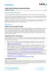
1.3.1 Dimensions
30
143 x 101 x 30 mm (L x W x H) with the metal plate
120 x 89 x 30 mm without metal plate
120.20
94.50
89.43
94.50
94.50
143
30
143
11.50
30
11.50
100.93
100.93
89.43
120.20
143
2
30
120.20
1.3.2 Weight
200 g (Net weight)
1.4 Power Requirements
1.4.1 System Power
Power input: DC +12V
1.4.2 RTC Battery
3 V/240 mAh
3
UBC-221 User Manual
General Introduction
1.5 Environment Specifications
1.5.1 Operating Temperature
0 ~ 40° C (32 ~ 104° F)
1.5.2 Relative Humidity
95% @ 40° C (non-condensing)
1.5.3 Storage Temperature
-20 ~ 60° C (-4 ~ 104° F)
1.5.4 Vibration Loading during Operation
1.5.5 EMC
CE, FCC Class B
UBC-221 User Manual
4
Chapter
2
2
Hardware
Functionality
This chapter introduces external I/
O and explains the setup procedures of the UBC-221 hardware.
2.1 Introduction
The following sections show the external connectors and pin assignments for applications.
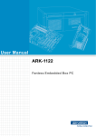
2.2 UBC-221 I/O Indication
COM GPIO
LAN PoE LAN
USB
Figure 2.1 UBC-221 front view
Figure 2.2 UBC-221 LED indication
Figure 2.3 UBC-221 left side view
UBC-221 User Manual
6
2.3.1 Power Input Connector
The UBC-221 comes with a DC-Jack header that carries 12V DC external power
input. The power connector can be fixed by a fastener which is an optional accessory. The fastener avoids power cables falling off.
2.3.2 COM Connector
The UBC-221 provides one terminal block 6-pin connector serial communication
interface port. The port can support RS-232 mode communication.
Figure 2.5 COM connector
Table 2.1: COM Connector Pin Assignment
Pin
Description
Pin
Description
1
COM_RTD
2
COM_RTS
3
COM_TXD
4
COM_CTS
5
GND
6
N/C
7
UBC-221 User Manual
Hardware Functionality
Figure 2.4 Power input connector
Chapter 2
2.3 UBC-221 I/O Connectors
2.3.3 Ethernet Connector (LAN)
The UBC-221 provides two RJ45 interface connectors. The Ethernet ports are fully
compliant with IEEE 802.3x 10/100 and CSMA/CD protocol support. The Ethernet
ports provides standard RJ-45 connector with LED indicators on the front side to
show Speed/Active status.
LAN: Left is speed (ON-100, OFF-10), Right is Active
PoE: Left is Active, Right is speed (ON-100, OFF-10).
Figure 2.6 Ethernet connector
2.3.4 USB Connector
The UBC-221 uses one USB interface connector that supports high-speed (480
Mbps), full-speed (12 Mbps), and low-speed (1.5 Mbps) operation.
Figure 2.7 USB connector
2.3.5 GPIO Connector
The UBC-221 supports two GPI and two GPO with terminal block interface. The GPI
has isolation support so it can protect against unexpected power damage.
Figure 2.8 GPIO connector
Table 2.2: GPIO Connector Pin Assignment
Pin
Description
1
GPO_0
2
GPI_0
3
GND
4
GND
5
GPO_1
6
GPI_1
UBC-221 User Manual
8
UBC-221 provides an SD slot. The SD card is essential for booting up the system
and for storage as UBC-221 has no onboard storage.
Note!
It is recommended to use only "Transcend and Sandisk" SD Cards
which Advantech has verified.
2.4 UBC-221 Hardware Installation
2.4.1 SD Card Installation
1.
2.
Remove the power cord.
Insert the SD Card directly into UBC-221 from the left side SD slot.
2.4.2 Mini-PCIe Card Installation
1.
Unscrew the two screws on the bottom of the case.
Figure 2.10 Unscrew the two screws
9
UBC-221 User Manual
Hardware Functionality
Figure 2.9 SD connector
Chapter 2
2.3.6 SD Connector
2.
Open the top cover.
Figure 2.11 Open the top cover
3.
Install your mini-PCIe card, close the top cover and put back the two screws on
the bottom of the case.
UBC-221 User Manual
10
To install the console cable you must:
1. Unscrew the two screws on the bottom of the case.
2. Open the top cover.
3. Install the console cable, close the top cover and put back the two screws on the
bottom of the case as shown in Figure 2.12.
Chapter 2
2.4.3 Console Installation
Hardware Functionality
Figure 2.12 Console Installation
2.4.4 Mounting Assembly method
The UBC-221 support flexible wall mounting holes so you can easily fix UBC-221
onto the wall. It also supports a DIN-rail kit (optional) for users who need to mount
UBC-221 onto a 35mm DIN-rail.
11
UBC-221 User Manual
UBC-221 User Manual
12
Chapter
3
3
Software Functionality
This chapter details the software
operating on UBC-221.
3.1 Test tools
All test tools must be verified on UBC-221, please prepare required test fixtures
before verifying each specified I/O. If you have any problems getting the test fixture,
please contact your Advantech contact window for help.
3.2 Debug Port Setting
UBC-221 can communicate with a host server (Windows or Linux) by using serial
cables. Common serial communication programs such as HyperTerminal, Tera Term
or PuTTY can be used in this case. The example as below describes the serial terminal setup using HyperTerminal on a Windows host:
1. Connect UBC-221 with your Windows PC by using a serial cable.
2. Open HyperTerminal on your Windows PC, and select the settings as shown in
Figure 3.1.
Figure 3.1 Debug port setting
3.
After the bootloader is programmed on the SD card, plug in the power cord to
power up UBC-221. The bootloader prompt will be displayed on the terminal
screen.
3.3 GPIO
# echo 0 > /sys/class/gpio/export
# echo 1 > /sys/class/gpio/export
# echo 2 > /sys/class/gpio/export
# echo 3 > /sys/class/gpio/export
# echo "out" > /sys/class/gpio/gpio0/direction
# echo "out" > /sys/class/gpio/gpio1/direction
# echo "in" > /sys/class/gpio/gpio2/direction
# echo "in" > /sys/class/gpio/gpio3/direction
# grep "" /sys/class/gpio/gpio{0..3}/direction
UBC-221 User Manual
14
Chapter 3
3.3.1 Connecting #0 and #3
# echo 0 > /sys/class/gpio/gpio0/value
# grep "" /sys/class/gpio/gpio{0,3}/value
Software Functionality
# echo 1 > /sys/class/gpio/gpio0/value
# grep "" /sys/class/gpio/gpio{0,3}/value
3.3.2 Connecting #1 and #2
# echo 0 > /sys/class/gpio/gpio1/value
# grep "" /sys/class/gpio/gpio{1,2}/value
# echo 1 > /sys/class/gpio/gpio1/value
# grep "" /sys/class/gpio/gpio{1,2}/value
15
UBC-221 User Manual
3.4 UART
# stty ‐F /dev/ttyS0 ‐echo
# cat /dev/ttyS0 &
# echo "1234567890" > /dev/ttyS0
3.4.1 Connecting #Tx and #Rx
# echo "1234567890" > /dev/ttyS0
3.5 LED
# echo 15 > /sys/class/gpio/export
# echo "out" > /sys/class/gpio/gpio15/direction
3.5.1 LED on
# echo 1 > /sys/class/gpio/gpio15/value
3.5.2 LED off
# echo 0 > /sys/class/gpio/gpio15/value
UBC-221 User Manual
16
Chapter 3
3.6 Wifi
Make Intel wifi card for example.
Intel Centrino Wireless-N 135
Model:135BNHMW
set wifi ssid to environment variable, SSID
set wifi password to environment variable, PSWD
17
Software Functionality
# ifconfig wlan0 up
# wpa_passphrase $SSID $PSWD > /tmp/wpa.conf
# wpa_supplicant ‐BDwext ‐iwlan0 ‐c/tmp/wpa.conf
# udhcpc ‐b ‐i wlan0
# ifconfig
# ping tw.yahoo.com
UBC-221 User Manual
3.7 LAN eth0
Make sure the DHCP service works in the connected LAN.
Remove network connection from both of the two LAN ports.
# ifconfig eth1 down
# ifconfig eth0 up
# ifconfig
Plug the network cable into the LAN port eth0 and wait for the "eth0: link to show up.
Checking if there is an IP or not.
UBC-221 User Manual
18
Chapter 3
# ifconfig
19
UBC-221 User Manual
Software Functionality
If there is no IP, please check the network connection and DHCP service.
If there is an IP, that means the network is working.
Using Ping to test network connection again.
3.8 LAN eth1
Make sure the DHCP service works in the connected LAN.
Remove network connection from both of the two LAN ports.
# ifconfig eth0 down
# ifconfig eth1 up
# ifconfig
Plugging the network cable into LAN port eth1 and waiting for "eth1: link to become
ready" and show up.
UBC-221 User Manual
20
Chapter 3
Checking if there is an IP or not.
# ifconfig
3.9 USB
Removing any USB devices.
Plug in one USB storage device with filesystem(fat32,ext2 or ext3). The following
message will show up and the file system will be mounted automatically.
21
UBC-221 User Manual
Software Functionality
If there is no IP, please check network connection and DHCP service.
If there is one IP, that means network is working.
Using ping to test network connection again.
# df
Unmounting USB storage device
# umount /media/sda1
3.10 3G
# ifconfig eth0 down
# ifconfig eth1 down
# pppd connect 'chat ‐v ‐s ‐t 10 "" "AT" "" "ATDT*99#" "CONNECT" ""'
user username password password /dev/ttyUSB2 460800 nodetach crtscts
debug usepeerdns defaultroute &
UBC-221 User Manual
22
Chapter 3
Software Functionality
Checking if DNS is ready.
# cat /etc/resolv.conf
Testing if WiFi connection works or not.
# ping www.google.com
23
UBC-221 User Manual
www.advantech.com
Please verify specifications before quoting. This guide is intended for reference
purposes only.
All product specifications are subject to change without notice.
No part of this publication may be reproduced in any form or by any means,
electronic, photocopying, recording or otherwise, without prior written permission of the publisher.
All brand and product names are trademarks or registered trademarks of their
respective companies.
© Advantech Co., Ltd. 2015