1
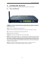
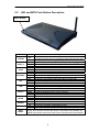
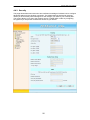
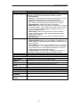
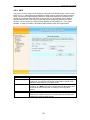
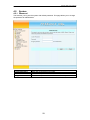
Freeway DSL User’s Manual
ADSL2/2+ IAD
Freeway DSL User’s Manual
Revision 0.3
March 2008
Freeway DSL User’s Manual
Table of Contents
1.
INTRODUCTION......................................................................................................................... 1
1.1
1.2
2.
FREEWAY DSL OVERVIEW.................................................................................................... 2
2.1
2.2
2.3
3.
PORTS AND BUTTONS ............................................................................................................. 2
LED AND WPS PUSH BUTTON DESCRIPTION......................................................................... 3
INSTALLING YOUR FREEWAY DSL ......................................................................................... 4
SETTING UP YOUR FREEWAY DSL...................................................................................... 5
3.1
4.
FEATURES .............................................................................................................................. 1
SYSTEM REQUIREMENT .......................................................................................................... 1
LOG INTO YOUR FREEWAY DSL ............................................................................................ 5
WEB CONFIGURATION ........................................................................................................... 6
4.1
OVERVIEW ............................................................................................................................. 6
4.2
INTERNET ............................................................................................................................... 7
4.2.1
VC Setting (Step 1)............................................................................................................ 7
4.2.2
WAN Setting (Step 2) ........................................................................................................ 8
Dynamic IP .............................................................................................................................................. 11
Static IP.................................................................................................................................................... 12
PPPoE ...................................................................................................................................................... 13
PPPoA...................................................................................................................................................... 14
Bridge....................................................................................................................................................... 14
4.2.3
WAN Status ..................................................................................................................... 15
4.2.4
ADSL Information........................................................................................................... 16
4.2.4.1
Statistics ..................................................................................................................... 16
4.2.4.2
Diagnostic.................................................................................................................. 17
4.3
TELEPHONY .......................................................................................................................... 18
4.3.1
Telephone Account.......................................................................................................... 18
4.3.2
Dial Plan ........................................................................................................................ 19
4.3.3
NAT Traversal ................................................................................................................ 20
4.3.4
Telephone Function ........................................................................................................ 21
4.3.4.1
Call Function ............................................................................................................. 21
4.3.4.2
Abbreviated Dialing................................................................................................... 22
4.4
WLAN................................................................................................................................. 23
4.4.1
RF Settings (Wireless Basic Settings) ............................................................................. 23
4.4.2
Multiple SSID ................................................................................................................. 25
4.4.3
Security ........................................................................................................................... 26
4.4.4
WPS ................................................................................................................................ 28
4.5
SYSTEM ................................................................................................................................ 29
4.5.1
Password ........................................................................................................................ 29
4.5.2
Network Time.................................................................................................................. 30
4.5.3
Firmware Update ........................................................................................................... 31
4.5.4
Reset ............................................................................................................................... 32
4.5.5
Event Log........................................................................................................................ 33
4.5.6
System Information ......................................................................................................... 34
4.6
ADVANCE ............................................................................................................................. 35
4.6.1
LAN................................................................................................................................. 35
4.6.1.1
LAN ............................................................................................................................ 35
4.6.1.2
STP Bridge................................................................................................................. 36
4.6.1.3
DHCP ........................................................................................................................ 37
4.6.2
NAT................................................................................................................................. 38
4.6.2.1
NAT Settings .............................................................................................................. 38
4.6.2.2
Virtual Server............................................................................................................. 39
4.6.2.3
Port Forwarding ........................................................................................................ 40
4.6.2.4
DMZ (DeMilitarized Zsone)....................................................................................... 41
4.6.3
Firewall .......................................................................................................................... 42
4.6.3.1
Firewall Settings ........................................................................................................ 42
4.6.3.2
IP/Port Filtering ........................................................................................................ 43
Freeway DSL User’s Manual
4.6.3.3
MAC Filtering............................................................................................................ 44
4.6.4
Network Setting............................................................................................................... 45
4.6.4.1
Static Routing............................................................................................................. 45
4.6.5
DNS................................................................................................................................. 46
4.6.5.1
DNS Server ................................................................................................................ 46
4.6.5.2
DDNS (Dynamic DNS) .............................................................................................. 47
4.6.6
Device Management ....................................................................................................... 48
4.6.6.1
TR-069 ....................................................................................................................... 48
APPENDIX A. TROUBLESHOOTING ............................................................................................ 49
APPENDIX B. SPECIFICATION ...................................................................................................... 50
Freeway DSL User’s Manual
1.
Introduction
The Freeway DSL ADSL2/2+ Wireless Ethernet Router is a highly integrated, voice enabled
broadband residential gateway that is positioned to enhance the user's broadband experience.
This new generation of platforms not only eases the deployment of DSL-based residential
gateways but also provides new opportunities for the service provider to derive additional
value from the emerging VoIP service.
The capabilities of the Freeway DSL allow for some highly advanced applications beyond just
typical DSL, but also WLAN access points and VoIP. Benefiting from the fact the Freeway
DSL also connects to a POTS line for a life line back up, some of these applications can
provide a competitive advantage over equivalent cable modem services. Also, given the
inclusion of a powerful processor and a WLAN connection, these services can be managed
from virtually anywhere in the home through an easy to use web-GUI management interface.
1.1
Features
Compliant to DSL Forum TR-048, TR-067 and TR-100 Interoperability Test
Feature-Rich TR-069 supports Remote Registration / Remote Authentication / Remote
Configuration
Complete solution for integration of ADSL, Router, Switch, WLAN, VoIP and DECT
WPS (Wi-Fi Protected Setup) support for easy WLAN client setup
STUN and Outbond Proxy for NAT Traversal
POTS Lifeline relay for power failure telephony operation
T.38 fax support
System management includes SNMP v1, v2, Telnet command line interface and web
interface
User can browse the Internet while talking on the phone simultaneously
Firmware upgrade through web management
Remote / Local configuration & management through Web / Telnet configuration &
management
1.2
System Requirement
In order to use the Freeway DSL, you must have the following:
ADSL service up and running on your telephone line
At least one activated SIP account for VoIP service
One or more computers each containing an Ethernet 10Base-T/100Base-T network
interface card (NIC)
For system configuration using the supplied web-based program: a web browser such as
Internet Explorer v 5.0 (or later), Firefox v2.0 (or later) and Netscape v 6.1 (or later).
1
Freeway DSL User’s Manual
2.
Freeway DSL Overview
Your Freeway DSL has ports, switches and LEDs. The features are listed below.
2.1
Ports and Buttons
POWER: Connecter for a power adapter. Using a power supply with a different voltage rating
will damage this product. Make sure to observe the proper power requirements. The power
requirement is 12 volts.
USB: Connector for USB devices like memory stick.
LAN1-4: Connector for Ethernet network devices, such as a PC, hub, switch, or router.
DSL: Connecter for accessing the Internet through ADSL line.
PSTN: Connector of PSTN life line.
PHONE1-2: Connecter of analog phone for VoIP communication.
RESET: Restore the default settings. You may need to place the Freeway DSL into its factory
defaults if the configuration is changed, you loose the ability to enter the Freeway DSL via the
web interface, or following a software upgrade, and you loose the ability to enter the Freeway
DSL. To reset the Freeway DSL, simply press the reset button for more than 5 seconds. The
Freeway DSL will be reset to its factory defaults and after about 30 seconds the Freeway DSL
will become operational again.
Warning: Incorrectly connecting telephony devices to the RJ-11 (phone) port on the
Telephony Interface can cause permanent damage to the Freeway DSL.
2
Freeway DSL User’s Manual
2.2
LED and WPS Push Button Description
WPS Button
LED
Status
Description
When a line fault condition on the VoIP connection. (This will occur if
On
ALARM
the outside world phone line is accidentally plugged into the VoIP jack.)
The VoIP connection is working properly.
Off
This VoIP line/port is off hook (the handset of phone is hanging).
On
VOIP1-2
Flash A phone call is in or out via VoIP line/port.
This VoIP line/port is on-hook or unused.
Off
The device is connected to a PSTN outlet.
On
PSTN
Flash A phone call is in or out via PSTN line/port.
The device is not connected to a PSTN outlet.
Off
The
device is successfully connected to Internet.
On
INTERNET
The
device is sending/receiving data from Internet.
Flash
The
WAN port is not connected to Internet.
Off
The
device
is successfully linked with ADSL line (DSLAM).
On
DSL
The
device
is
trying to link with ADSL line (DSLAM).
Flash
The
device
is
not
linked with ADSL line (DSLAM).
Off
A
USB
device
is
connected
to the USB port.
On
USB
The
connected
USB
device
is sending/receiving data via USB port.
Flash
No
USB
device
is
connected
to the USB port.
Off
The
LAN
port
is
connected
to
Ethernet device.
On
LAN1-4
The
data
is
sending/receiving
via this LAN port.
Flash
The
LAN
port
is
not
connected
to Ethernet device.
Off
The
device
is
ready
for
wireless
clients to connect.
On
WLAN
The
data
is
sending/receiving
via
wireless.
Flash
The
device
is
not
ready
for
wireless
clients to connect.
Off
The
device
is
power
on.
ON
POWER
The device is power off.
Off
The
device is in wireless configuration process.
On
WPS
The
device is not process any wireless configuration.
Off
Push the WPS button for about 4 seconds, the WPS LED will then light up and
WPS
flashing. At this moment, click the PBC button in the wireless client software, the
Button
wireless client will then scan and connect to the AP (Freeway DSL) automatically.
3
Freeway DSL User’s Manual
2.3
1.
2.
3.
Installing your Freeway DSL
Locate an optimum location for the Freeway DSL.
For connections to the Ethernet and DSL interfaces, refer to the Quick Start Guide.
Connect the Power Adapter. Depending upon the type of network, you may want to put
the power supply on an uninterruptible supply. Only use the power adapter supplied with
the Freeway DSL. A different adapter may damage the product.
Now that the hardware installation is complete, continue on to set up your Freeway DSL.
4
Freeway DSL User’s Manual
3.
Setting up Your Freeway DSL
This section guides you through configuring your Freeway DSL. Before setting up your
Freeway DSL, make sure you have followed the Quick Start Guide. You should have your
computers configured for DHCP mode and have proxies disabled on your browser. If you do
not get the page as shown below, you may need to delete your temporary Internet files by
flushing the cached web pages.
3.1
Log into Your Freeway DSL
Use the following procedures to log in to your Freeway DSL.
1. Open your web browser. Type the default IP address of the Freeway DSL
http://192.168.1.1 and press Enter.
The Welcome page appears.
2.
3.
Enter user name as admin and password as admin (case sensitive).
Click LOGIN.
The main page appears.
You can change the password in System->Password page at any time.
Note
The Web Application is displayed as shown below. This page displays the Freeway DSL’s
current status.
5
Freeway DSL User’s Manual
4.
Web Configuration
4.1
Overview
This page displays the firmware version, DSP version, interface status and Internet
connection. This information will vary depending on the Internet connection status.
6
Freeway DSL User’s Manual
4.2
Internet
4.2.1 VC Setting (Step 1)
The Freeway DSL supports multiple channel operation modes and is bridge mode enabled by
factory default. There is a 1483-bridged mode PVC 1/32 in system.
Field
Description
Encapsulation The encapsulation can be configured to:
LLC/SNAP
Mode
VCMUX
Freeway DSL support the full range of VPI/VCI meaning:
VPI/VCI
VPI range 00H - FFH
setting
VCI range 0000H -FFFFH
Click on Add to add the parameters specified in all the 3 fields.
7
Freeway DSL User’s Manual
Freeway DSL Supports the following ATM QoS traffic classes per VC:
UBR: Unspecified Bit Rate.
CBR: Constant Bit Rate.
NRT-VBR: Variable Bit Rate-non real time.
When you select this option for QoS mode, the following additional fields
become available: Minimum Cell Rate, Sustainable Cell Rate, Maximum
Burst Size.
RT-VBR: Variable Bit Rate-real time.
When this option is selected for QoS mode, the following additional fields
become available: Sustainable Cell Rate, Maximum Burst Size.
UBR+: This is a special service class derived from UBR.
When QoS Mode is set to this option, the following field appears
additionally: Minimum Cell Rate.
Peak Cell Rate This parameter is required for all ATM traffic classes and is configured in
cells/s.
This parameter is required for VBR-rt (Variable Bit Rate - real time)
Cell Delay
connections. It will only be displayed for this traffic class. The value is
Variation
specified in ms to specify the maximum allowed jitter.
QoS Mode
4.2.2 WAN Setting (Step 2)
This page allows you to configure multiple VCCs and shows the default interface and the
default gateway configured on the device. Freeway DSL supports up to 15 VCCs. You can
click on any of the radio buttons to select the default interface or the default gateway.
8
Freeway DSL User’s Manual
You can choose one of the WAN interfaces being configured and then click APPLY. The
WAN configuration screen will then displayed as shown below.
This page shows the action performed on clicking any radio button for default interface or
default gateway. Once you click on any of the radio buttons you will be asked to confirm the
same. If click OK the default interface or the default gateway will be configured on the WAN
connection selected. Otherwise changes will not be applied.
9
Freeway DSL User’s Manual
The WAN Settings screen contains the details as shown below.
Field
Attached Channel
Dynamic IP
Address
Static IP Address
PPPoE
PPPoA
Bridge
Delete
Description
This is the PVC being configured.
Obtain an IP address automatically from your service provider.
Uses a static IP address. Your service provider gives a static IP
address to access Internet services.
PPP over Ethernet is a common connection method used for xDSL.
PPP over ATM is a common connection method used for xDSL.
Bridge mode is a common connection method used for xDSL modem.
To delete this VCC setting.
10
Freeway DSL User’s Manual
Dynamic IP
To configure the WAN interface to dynamically obtain an IP address, select the Dynamic IP
Address button on the WAN settings page and click Next. A screen is displayed as shown
below.
Field
Protocol
Description
This option allows to select the protocols:
RFC 2684 Ethernet over ATM
RFC 2364 IP over ATM
To enter the VLAN ID for which membership needs to be added for the
VLAN ID
selected port.
VLAN Priority Specify the priority of VLAN.
Tagging outgoing frames with VLAN-Tagged.
TAG
Untagging outgoing frames with VLAN-Tagged.
UN-TAG
11
Freeway DSL User’s Manual
Static IP
To configure the WAN interface to use a static IP address, select the Static IP Address
button on the WAN settings page and click Next. A screen is displayed as shown below.
Field
IP address
assigned by your
ISP
Subnet Mask
ISP Gateway
Address
Protocol
Description
To enter the IP Address of Freeway DSL.
To enter the Subnet Mask of Freeway DSL.
To enter the Gateway address of the Freeway DSL.
Select the supported Protocol:
Classic IP, which is the classical IP over ATM
RFC 2684 Ethernet over ATM
RFC 2684 IP over ATM
12
Freeway DSL User’s Manual
PPPoE
To configure the WAN interface to use PPPoE, select the PPPoE button on the WAN
settings page and click Next. A screen is displayed as shown below.
Field
User Name
Password
Please retype your
password
MTU (1400-1492)
Description
To enter a name to use the PPPoE session.
To enter a password of the login user.
To enter the password again to reconfirm.
To enter the maximum connection units of the PPPoE. The MTU range
is 1400 to 1492 bytes.
This feature allows to automatically re-connect to the service provider
Dial on Demand
once the connection was lost. Can be enabled or disabled.
Maximum Idle Time To enter the maximum idle time for disconnecting the connection.
This feature allows to enable/disable a PPPoE relay session.
Relay LAN site
PPPoE Session
13
Freeway DSL User’s Manual
PPPoA
To configure the WAN interface to use PPPoA, select the PPPoA button on the WAN
settings page and click Next. A screen is displayed as shown below.
Field
User Name
Password
Please retype your
password
MTU (1400-1500)
Dial on Demand
Description
To enter a name to use the PPPoA session.
To enter a password of the login user.
To enter the password again to reconfirm.
To enter the maximum connection units of the PPPoE. The MTU range
is 1400 to 1500 bytes.
This feature allows to automatically re-connect to the service provider
once the connection was lost. Can be enabled or disabled.
The option Bridge enables the bridge mode, which is a common connection method used for
xDSL modem. The entire VCC setting can be disabled using the Disable option.
Bridge
The option Bridge enables the bridge mode, which is a common connection method used for
xDSL modem. The entire VCC setting can be disabled using the Disable option. To configure
the Bridge settings, select the Bridge button on the WAN settings page and click Next.
14
Freeway DSL User’s Manual
4.2.3 WAN Status
This page shows the WAN connection status.
Field
VCC
Connection Type
Description
For the currently configured WAN interface, this gives the VPI/VCI
and Encapsulation Method.
The type of the connection mode in which Freeway DSL is
configured.
Displays the connection status of the VCC.
Displays the IP address in use.
Displays the netmask in use.
Displays the configured connection name
Status
IP
Netmask
Configured
Connection Name
Gateway Information Provides information about the gateway.
Provides information about the primary and secondary DNS.
DNS Information
The control buttons shown against few VCCs are explained below.
Field
Description
This button appears only for VCCs of PPPoA and PPPoE type of WAN links.
Connect
On clicking this button, it tries to establish PPP link.
Disconnect This button too appears only for VCCs of PPPoA and PPPoE type of WAN
links. On clicking this button, it brings down the PPP link.
This button is shown against VCCs of Dynamic IP Address Type. On clicking
Release
this button, it releases the DHCP allocated IP address.
This button too appears for VCCs of Dynamic IP Address Type. On clicking this
Renew
button, it tries to renew the DHCP lease of allocated IP address.
Note: The WAN links of other types like Static IP address or Bridge type can not be controlled
from this web page.
15
Freeway DSL User’s Manual
4.2.4 ADSL Information
4.2.4.1
Statistics
This page shows the ADSL line statistics information.
16
Freeway DSL User’s Manual
4.2.4.2
Diagnostic
This page shows the ADSL tone diagnostic information. You will not typically need to view this
data, but you may find it helpful when working with your ISP to diagnose network and Internet
data transmission problems.
17
Freeway DSL User’s Manual
4.3
Telephony
4.3.1 Telephone Account
This page allows you to configure the Internet telephone account. Your ITSP (Internet
telephone service provider) should provide you with the sufficient information.
Field
Phone Number
Display Name
Proxy Server
Proxy Port
Registrar Server
Registrar Port
User Name
Password
Description
Configure the number for this account.
Configure the display name for this account.
Configure the proxy server for this account.
Configure the proxy port for this account. Default is 5060.
Configure the register server for this account.
Configure the register port for this account. Default is 5060.
Configure the user name of this account for authentication.
Configure the user password of this account for authentication.
18
Freeway DSL User’s Manual
4.3.2 Dial Plan
This page allows you to configure the dial plan for the Freeway DSL.
Field
Dial Plan List
Dial Plan
Description
Shows the dial plan you configured in the dial plan field
To enter the dial plan settings.
19
Freeway DSL User’s Manual
4.3.3 NAT Traversal
STUN (Simple Traversal of UDP through NATs (Network Address Translation)) is a protocol
for assisting devices behind a NAT firewall or router with their packet routing. This page
allows you to configure the NAT traversal for the Internet telephone to penetrate through
firewall.
Field
None
STUN Server
Server Port
STUN Need Mask
Client Port
Outbound Proxy
Proxy Port
Description
Select the radio to disable STUN Traversal function.
Enter the IP address of STUN server.
Enter the port number to be used for the STUN server.
Enter the subnet mask of STUN server.
Enter the port number to be used for the STUN client (e.g. Freeway
DSL).
Enter the IP address of outbound proxy server.
Enter the port number to be used for the outbound proxy server.
20
Freeway DSL User’s Manual
4.3.4 Telephone Function
4.3.4.1 Call Function
This page allows you to select the telephone features you want to apply to your telephone
account.
21
Freeway DSL User’s Manual
4.3.4.2 Abbreviated Dialing
This page allows you to configure the abbreviated dialing for Port 1and 2. Abbreviated dialing
allows stored numbers to be called by dialing a short 1 or 2 digit code from your home phone.
You can set up to 20 entries totally in Port 1 and Port 2 pages. When user A calls B, if B‘s
name is in the abbreviated dialing list, B’s name will be shown on the phone. If not, only B’s
phone number will be displayed.
Field
Position
Name
PhoneNumber
URI
Description
To enter the location from 0 to 9 to store the entry.
To enter the name for this phone number.
To enter the phone number. It is recommended that using the digits to
be the name and it could be also used as the speed-dial numbers.
Input the Line Number or IP address.
22
Freeway DSL User’s Manual
4.4
WLAN
4.4.1 RF Settings (Wireless Basic Settings)
This page contains all of the wireless basic settings. Most users will be able to configure the
wireless connection and get it working properly using the setting on this screen.
Field
Wireless
Channel ID
SSID Mode
Operation Rate
CTS Protection
Mode
Preamble Mode
Description
Select to enable or disable wireless.
Select the operation channel for the wireless.
A Service Set Identifier (SSID) value that controls access to a wireless
network. This
field allow to:
Advertise SSID: The client can scan/discover the SSID.
Hide SSID: The SSID is hidden and only if you know the SSID you
can connect to Freeway DSL.
Allows to specify the operation mode to be:
Auto
802.11B rate only
802.11G rate only
If CTS (Clear-To-Send) Protection Mode is set to ON. The AP will
automatically use CTS Protection Mode when the Wireless-G
products are experiencing severe problems and are not able to
transmit to the AP in an environment with heavy 802.11b traffic. This
function boosts the AP’s ability to catch all Wireless-G transmissions
but will severely decrease the performance. If you do not want to use
CTS Protection Mode at all, select OFF (default).
Allows to specify the preamble mode to:
Auto
Long Preamble
Short Preamble
23
Freeway DSL User’s Manual
Power Level
DTIM Interval
Beacon Interval
RTS Threshold
Fragment
Threshold
Select the output power of wireless radio to be 20%, 40%, 60%, 80%
or 100%. Unless you are using this Freeway DSL in a really wide
space, you may not have to set radio power to 100%. The wider
coverage the more security risk (malicious or unknown users in
distance will be able to reach the Freeway DSL).
Specifies the interval of the Delivery Traffic Indication Message
(DTIM). A DTIM field is a countdown field informing clients of the next
window for listening to broadcast and multicast messages. When the
AP has buffered broadcast or multicast messages for associated
clients, it sends the next DTIM with a DTIM Interval value. Its clients
hear the beacons and awaken to receive the broadcast and multicast
messages.
Specifies the interval between beacon packets, which IEEE 802.11
systems use to synchronize clients. Beacon packets contain timing
and other information that is broadcast over the airwaves. Any station
that receives the beacon packet can then synchronize with the system
broadcasting beacons. The default value of the beacon period is 100
milliseconds.
Specifies the data packet size beyond which the low-level RF protocol
invokes RTS/CTS flow control. A small value causes RTS packets to
be sent more often, which consumes more of the available bandwidth
and reduces the throughput of other network packets. However, small
values help the system recover from interference or collisions, which
can occur in environments with obstructions or metallic surfaces that
create complex multipath signals.
Should you encounter inconsistent data flow, only minor reduction of
the default value, 2312, is recommended. If a network packet is
smaller than the preset RTS threshold size, the RTS/CTS mechanism
will not be enabled. The Router sends Request to Send (RTS) frames
to a particular receiving station and negotiates the sending of a data
frame. After receiving an RTS, the wireless station responds with a
Clear to Send (CTS) frame to acknowledge the right to begin
transmission.
Defines the largest RF packet that the client adapter sends without
splitting the packet into two or more smaller fragments. If a single
fragment experiences interference during transmission, only that
fragment must be resent. Fragmentation generally reduces throughput
because the packet overhead for each fragment consumes a higher
portion of the RF bandwidth.
24
Freeway DSL User’s Manual
4.4.2 Multiple SSID
This page allows you to configure multiple SSID for Freeway DSL.
Field
SSID
Enable SSID
SSID Name
Description
Select the SSID and configure its name in the SSID Name field.
Check to enable this SSID.
To enter the Name for the selected SSID.
25
Freeway DSL User’s Manual
4.4.3 Security
This page allows advanced users who have sufficient knowledge of wireless LAN to configure
advanced settings for the wireless connection. The default settings shall not be changed
unless you know exactly what will happen for the changes you made to your Freeway DSL.
This screen allows you to setup the wireless security. Enable WEP or WPA by configuring
encryption keys can prevent unauthorized access to your WLAN.
26
Freeway DSL User’s Manual
Field
SSID
Encryption Type
Authentication Type
Active Key
Key 1 ~4 (Hex 10/26)
Radius Server Setup
NAS Identifier
Radius Server
address
Radius Server Port
Radius Server
Secret
1x Key Length
WPA
PSK Key
Enable Passphrase
Group Key
Renewable
Group Key renew
Interval
Description
Select the SSID and configure the necessary security.
Select the security type you need. To secure your wireless
network, it’s strongly recommended to enable this feature.
No Encryption
WEP 64: (10 digits) Make sure that all wireless devices on your
network are using the same encryption level and key.
WEP 128: (26 digits) Make sure that all wireless devices on
your network are using the same encryption level and key.
Standard 802.1x: Select to use 802.1x encryption.
WPA (TKIP): WPA uses Temporal Key Integrity Protocol (TKIP)
for data encryption. TKIP utilized a stronger encryption method
and incorporates Message Integrity Code (MIC) to provide
protection against hackers.
WPA2 (AES): WPA2 uses Advanced Encryption Standard
(AES) for data encryption. AES utilized a symmetric 128bit
block data encryption.
TKIP/AES: Supports both WPA (TKIP) and WPA2 (AES) for
data encryption.
Used to specify the WLAN authentication type which can be:
OPEN AUTHEN: Enables your client adapter, regardless of its
WEP settings, to attempt to authenticate and communicate with
an access point.
Radius Server: It uses an external RADIUS server to perform
user authentication. To use WPA RADIUS, enter the IP address
of the RADIUS server, the RADIUS port (default is 1812) and
the shared secret from the RADIUS server.
Pre-Share Key: Pre-Shared Key authentication is based on a
shared secret that is known only by the parties involved.
Used to specify the active key to be used.
Specifies the value of key 1 ~ 4.
Specifies the Radius server identifier.
Configures the IP Address of the Radius server.
Configures the Radius server Port number.
Configures the Radius server secret access code.
Configures the key length.
Specifies the PSK key.
Enables/Disables the use of the passphrase.
Enables/Disables if the Key renewable.
Configure the Key renew interval time (period).
27
Freeway DSL User’s Manual
4.4.4 WPS
This page is used to configure the settings for WPS (Wi-Fi Protected Setup). It uses a pushbutton or a 4- or 8-digit personal identification number (PIN) to simplify the secure network
setup. The PIN can be generated by software or preprogrammed into a client device and
printed on an included card. With WPS, Freeway DSL can automatically set the SSID or
network name as part of the setup process and provide strong encryption keys to client
devices. You do not need to configure SSID, wireless security setting, etc., in the client
software. In order to use WPS, the wireless client software must also support WPS.
Field
WPS
WPS Status
Start PBC
Client PIN Number
Start PIN
Description
Select to enable/disable WPS function.
If the wireless security (encryption) function of the Freeway DSL is
properly set, you will see “Configured” radio button in action mode,
otherwise, “UnConfigured” is in action mode.
Click this button to start PBC (Push-Button Configuration) setup
procedure. The WPS LED on the Freeway DSL will blink slowly for 2
minutes when the Freeway DSL is waiting for incoming WPS
request.
Enter the PIN number of the wireless client you wish to connect.
Click this button to start PIN setup procedure. The WPS LED on the
Freeway DSL will blink slowly for 2 minutes when the Freeway DSL
is waiting for incoming WPS request.
28
Freeway DSL User’s Manual
4.5
System
4.5.1 Password
The first time you log into the system with default password. This page allows you to change
the password for administrator.
Field
Current Password
Password
Re-type Password
Description
Enter the old password in this field.
Enter the new password in this field.
Enter the new password in this field to confirm the password.
29
Freeway DSL User’s Manual
4.5.2 Network Time
Simple Network Timing Protocol (SNTP) is a protocol used to synchronize the system time to
the public SNTP servers. The Freeway DSL supports SNTP client functionality in compliance
with IETF RFC2030. This page allows you to manually configure the time and select Time
Zone. Also, you can enable SNTP client update function and configure the SNTP server to let
the Freeway DSL synchronize with the public SNTP servers.
Field
Current Time
SNTP Client
Set Time Zone
Enable SNTP
client update
SNTP Server
Description
The current time of the specified time zone. You can set the current time
by yourself or configured by SNTP.
To enable/disable SNTP client function. You must enable SNTP client to
allow updating system clock.
Select The time zone in which the Freeway DSL resides.
Enable the SNTP client to update the system clock.
Enter the network time server for the Freeway DSL to synchronize with.
30
Freeway DSL User’s Manual
4.5.3 Firmware Update
The system software used by this Freeway DSL is called “firmware”. This page allows you to
upgrade the firmware to newer version.
To upgrade firmware, please follow the following instructions:
1.
Click the Browse button to select the firmware file.
2.
Confirm your selection.
3.
Click the Apply button to start upgrading.
IMPORTANT! Do NOT power off the Freeway DSL or press the Reset button while this
procedure is in progress.
31
Freeway DSL User’s Manual
4.5.4 Reset
This page allows you to reset the Freeway DSL.
Field
Reset
FactoryReset
Description
Reboot the device while still remain its current settings
Reset the device to default settings will erase all the current settings and
you need to re-configure the settings after reboot.
IMPORTANT! Do NOT power off the Freeway DSL or press the Reset button while this
procedure is in progress.
32
Freeway DSL User’s Manual
4.5.5 Event Log
This page shows the logged information including any attempts that have been made to
access your network.
Field
Download
Clear
Refresh
Description
To download the log file to the computer.
Clear the logs in this page.
To retrieve system event and update the log file.
33
Freeway DSL User’s Manual
4.5.6 System Information
This page shows the LAN, Ethernet ports and device information.
34
Freeway DSL User’s Manual
4.6
Advance
4.6.1 LAN
4.6.1.1 LAN
This page shows the current setting of LAN interface. You can set IP address and subnet
mask for LAN interface in this page.
Field
IP Address
Subnet Mask
Description
Enter the IP address of Freeway DSL.
Enter the subnet mask for this network.
35
Freeway DSL User’s Manual
4.6.1.2 STP Bridge
This page allows you to enable STP Bridge feature to configure Freeway DSL as bridge mode.
Field
Enable STP Bridge
Description
Check to enable STP bridge feature.
36
Freeway DSL User’s Manual
4.6.1.3 DHCP
The Freeway DSL supports the Dynamic Host Configuration Protocol (DHCP). This page is
used to configure the Freeway DSL to be a DHCP server or a DHCP Relay agent.
DHCP Server Configuration
By default, the Freeway DSL is configured as a DHCP server, with a predefined IP address
pool from 192.168.1.2 to 192.168.1.254 (subnet mask 255.255.255.0).
Field
Description
To select DHCP mode to be Disable, Server or Relay Agent.
DHCP Mode
DHCP Server
To enter the starting IP Address of the DHCP server pool.
IP Pool Starting
Address
To enter the ending IP Address of the DHCP server pool.
IP Pool Ending
Address
To select the lease time of the DHCP server.
Lease Time
To enter the Domain Name of the DHCP server.
Local Domain
Name (optional)
DHCP Relay Agent
Select a WAN interface for the relay.
DHCP Relay
IP address of the DHCP server on the interface showed, to which the
DHCP Server IP
DHCP requests are relayed.
37
Freeway DSL User’s Manual
4.6.2 NAT
4.6.2.1 NAT Settings
This page allows you to enable NAT feature.
38
Freeway DSL User’s Manual
4.6.2.2 Virtual Server
This page allows you to configure the Freeway DSL as a virtual server. This enables remote
users to access services at your local site from the Internet.
Field
Private IP
Remote IP
Private Port
Type
Public Port
Enabled
WAN
Interface
Description
To enter a private IP address of specified entry.
To enter a remote IP address of specified entry.
To enter a private Port number of the specified entry.
To select virtual server protocol type of the specified entry.
To enter a public port number of the internet user to access the virtual server.
To enable the specified entry of the virtual server.
To select the WAN interface to be used for the virtual server.
39
Freeway DSL User’s Manual
4.6.2.3 Port Forwarding
This page allows you to configure port forwarding rules. Add a Port Forwarding entry will
create a tunnel through your firewall so that the computers on the Internet can communicate
to one of the computers on your LAN on a single port.
Field
Server IP
Mapping Ports
Description
To enter the local IP address to route the packets.
To enter the port number for specific applications.
40
Freeway DSL User’s Manual
4.6.2.4 DMZ (DeMilitarized Zsone)
This page allows you to configure a local PC to be exposed on the Internet for unrestricted
two-way Internet access.
Field
Description
To enable/disable DMZ function.
Enable
IP Address of Virtual DMZ Host Enter the IP Address of the DMZ host.
41
Freeway DSL User’s Manual
4.6.3 Firewall
4.6.3.1 Firewall Settings
This page allows you to enable or disable firewall feature.
42
Freeway DSL User’s Manual
4.6.3.2 IP/Port Filtering
This page allows you to restrict specific data packets through the Freeway DSL.
Field
Enable Packet
Filter
Source IP
Source Port
Destination IP
Destination Port
Protocol
Description
To enable or disable the Packet Filtering feature of Freeway DSL. To
enable, select the check box.
Filter IP Address range of the local machine under Freeway DSL.
Filter Port number range of the local machine under Freeway DSL.
IP address of the destination.
Port address of the destination.
This is used for filter protocol. Select TCP or UDP to filter the protocol
type packets from the local machines.
Ingress Interface Input interface of the packet.
Egress Interface Output interface of the packet.
To provide more IP Addresses of the WAN interface.
Enable
On pressing Add button, the screen shown in next page is displayed.
Add
The options available in the Add a Packet Filtering Rule window are
described in next page.
43
Freeway DSL User’s Manual
4.6.3.3 MAC Filtering
This page allows you to define rules to allow or deny specific packets through the Freeway
DSL based on source MAC address, destination MAC address and traffic direction.
Field
Description
MAC Address Control To disable, deny all or permit all the MAC address control.
MAC Address Control List
To specify whether the particular MAC address is disabled, denied
Policy
or permitted.
To assign the blocking MAC address for local machine.
MAC Address
To select the day(s) and time slot when the policy has to be
Date/Time Select
applied on the MAC address provided. The Begin time entered
should not be later than the End time and should be in the 24 hour
format (hh:mm).
Click this button to add the specified MAC address entry in the list.
Add
44
Freeway DSL User’s Manual
4.6.4 Network Setting
4.6.4.1 Static Routing
The Routing page allows you to define specific route for your Internet and network data. Most
users do not need to define routes. On a typical small home or office LAN, the existing routes
that set up the default gateways for your LAN hosts and for the Freeway DSL provide the
most appropriate path for all your Internet traffic.
Field
Destination LAN IP
Subnet Mask
Gateway
Description
To enter the IP Address of routing entry.
To enter the Subnet Mask of routing entry.
To enter the Gateway address of routing entry.
45
Freeway DSL User’s Manual
4.6.5 DNS
4.6.5.1 DNS Server
This page allows you to configure the DNS server IP address.
Field
Description
Domain Name Server Enter the DNS address of the primary DNS server.
(DNS) Address
Enter the address of the secondary DNS server, if available.
Secondary DNS
Address (optional)
46
Freeway DSL User’s Manual
4.6.5.2 DDNS (Dynamic DNS)
Each time your device connects to the Internet, your ISP assigns a different IP address to
your device. In order for you or other users to access your device from the WAN-side, you
need to manually track the IP that is currently used. This page allows you to register your
device with a DNS server and access your device each time using the same host name.
Field
Enable DDNS Support
Interface
Select DDNS Server
dhs/syndns/dyns
Description
Used to enable the Dynamic Domain Name Server support.
Choose one from the drop-down list. DDNS is enabled or disabled
on a PVC interface basis.
For this server you have to specify:
Host Name: The domain name to be registered with the DDNS
server.
User Name: The user name of your registered account.
Password: The password or key of your registered account.
47
Freeway DSL User’s Manual
4.6.6 Device Management
4.6.6.1 TR-069
The TR-069 (CPE WAN Management Protocol) function can secure remote host access to
your Freeway DSL from LAN and WLAN interfaces for some services provided by it.
Field
Description
Authenticate ACS Check to enable the authentication to ACS.
To enter the ACS URL (HTTP Address and Port Number). The URL can
ACS URL
be either http or https.
Check to enable periodic inform of ACS authentication.
Periodic Inform
Enable
To enter the inform interval time.
Periodic Inform
Interval
CPE Initiated Connection Request
User Name for authentication to ACS.
User Name
Password for authentication to ACS.
Password
ACS Initiated Connection Request
To enter the URL of CPE.
CPE URL
User Name for authentication to ACS.
User Name
Password for authentication to ACS.
Password
48
Freeway DSL User’s Manual
Appendix A. Troubleshooting
Below is a list of commonly asked questions. Before calling technical support, please look
through these issues to see if they help solve your problem.
The Freeway DSL is not functional.
1.
2.
3.
4.
5.
6.
7.
Check to see that the POWER LED is lit and than the network cables are installed
correctly. Refer to the Quick Start Guide for more details.
Check to see that the LAN and WAN LEDs are lit.
Check the settings on your PC. Again, refer to the Quick Start Guide for more details.
Check the Freeway DSL’s settings.
From your PC, can you PING the Freeway DSL? Assuming that the Freeway DSL has
DHCP enabled and your PC is on the same subnet as the Freeway DSL, you should be
able to PING the Freeway DSL.
Can you PING the WAN? Your ISP should have provided the IP address of their server.
If you can ping the Freeway DSL and your protocols are configured correctly, you should
be able to ping the ISPs network. If you cannot PING the ISPs network, make sure your
using the correct protocols with the correct VPI/VCI values.
Make sure NAT is enabled for your connection. If NAT is disabled you the Freeway DSL
will not route frames correctly.
I can’t connect to the Freeway DSL.
1.
2.
3.
4.
Check to see that the POWER LED is lit and that the network cables are installed
correctly.
Make sure that your PC and the Freeway DSL is on the same network segment. The
Freeway DSL’s default IP address is 10.10.10.250. If you are running a Windows based
PC, you can open a DOS window and type IPCONFIG; make sure that the network
adapter that is connected to the Freeway DSL is within the same subnet.
Also, your PC’s Subnet Mask should match the Freeway DSL’s subnet mask. The
Freeway DSL has a default subnet mask of 255.0.0.0.
If this still does not work, press the RESET button. This will place the Freeway DSL into
its factory default state. Go through the above procedures again.
The DSL LED continues to blink but does not go solid.
1.
2.
3.
Make sure you have DSL service. You should get some kind of information from your
ISP which states that DSL service is installed. You can usually tell if the service is
installed by listening to the ADSL phone line; you will hear some high-pitched noise. If
you do not hear high-pitched noise, contact your ISP.
This means that the DSL line is trying to train but for some reason it cannot establish a
valid connection. The main cause of this is that you are too far away from the central
office. Contact your DSL service provider for further assistance.
Verify that the DSL line is connected directly to the wall and to the line input on the
Freeway DSL.
49
Freeway DSL User’s Manual
Appendix B. Specification
Physical Interface
One ADSL port for WAN
Four 10/100 Mbps Fast Ethernet ports for LAN
IEEE 802.11 b/g Wireless AP with WPS auto setup
Two VoIP FXS ports and one FXO port for emergency
ADSL Compliance
Support Multi mode standards (ANSI T1.413 Issue 2, G.dmt, G.lite)
ADSL2 G.dmt.bis (G.992.3)
ADSL2 G.lite.bis (G.992.4)
ADSL2+ (G.992.5)
Reach Extended ADSL (RE ADSL)
ATM Protocols
15 PVCs Support
Adaptation Layers AAL5, AAL2 and AAL0 Support
OAM F5 Loopback
PPP Support
PPP over ATM PVC (RFC 2364&RFC1577)
PPP over Ethernet (RFC 2516)
PAP (Password Authentication Protocol), CHAP (Challenge Handshake Authentication
Protocol) and MS-CHAP (Microsoft Challenge Handshake Authentication Protocol)
Networking Stack
NAT: Static Port Mappings, NAT Policies, UPnP NAT Traversal
Packet backbone: ICMP, ARP, RARP, UDP, TCP, Multicast, IPv4, QoS, DHCP Client /
Relay / Server, DNS Relay / Proxy, ToS Bits, IGMP Proxy
Bridging: IEEE 802.1d Bridge
Routing: Static route, RIP v1 / v2
Firewall / Security
SPI (Stateful Packet Inspection) Firewall / Secure session management
Packet Filtering
Port Forwarding DMZ
IPSEC / PPTP Pass through
IP and MAC Spoofing Protection
Secure Shell (SSH) v2
Quality of Service (QoS)
Constant Bit Rate (CBR), Real-Time Variable Bit Rate (VBR-rt)
Non-Real-Time Variable Bit Rate (VBR-nrt)
Unspecified Bit Rate (VBR)
Wireless
Standards: IEEE 802.11b/g
Frequency Band: 2.300 to 2.500 GHz ISM band
Modulation: OFDM with BPSK, QPSK, 16 QAM, 64 QAM
FEC Coding Rates: 1/2, 1/3, 1/4
Hardware Encryption: AES, TKIP, WEP
Quality of Service: 802.11e draft
Supported Bit Rate: 54M, 48M, 36M, 24M, 18M, 12M, 11M, 9M, 6M, 5.5M, 2M, 1Mbps
WPS support for easy client setup
50
Freeway DSL User’s Manual
Voice over IP Protocols
RFC 2976 SIP INFO
RFC 3261 SIP V2.0
Voice Codecs
G.711 Appendix 1, 2
G.723.1A
G.726
G.729AB
Fax Protocol
T.38U
NAT Traversal
STUN
Out-bond Proxy
CID Generation
Bellcore / NTT / ETSI
Voice Application Features
Generation Application Features
Handling of 10 SIP Accounts
Display name and address
SIP Network re-registration
Analyzing network environment
Debugging options, especially SIP
DTMF
Inband
SIP INFO method
RTP Payload
Basic
Tone generation / Dectection
Echo cancellation
CID generation (Calling ID)
Call Features
Hold / Retrieve
Transfer
Conferencing
Waiting
Completion on busy subscriber
Deflection
Forwarding unconditional
Forwarding busy
Forwarding no response
E.164 numbering plan support
Anonymous call
Environmental Specification
Power Input: Device input power at 12VDC/1.5A
Power Consumption: 9.54W
Operating Temperature: 0 °C to 40 °C
Humidity: 95% non-condensing
51