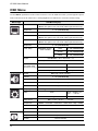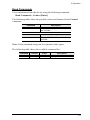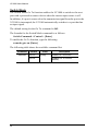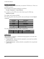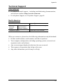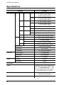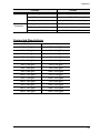
1
Universal A/V to HDMI Switch with Scaler VC1080 User Manual www.aten.com VC1080 User Manual EMC Information FEDERAL COMMUNICATIONS COMMISSION INTERFERENCE STATEMENT This equipment has been tested and found to comply with the limits for a Class A digital device, pursuant to Part 15 of the FCC Rules. These limits are designed to provide reasonable protection against harmful interference when the equipment is operated in a commercial environment. This equipment generates, uses, and can radiate radio frequency energy and, if not installed and used in accordance with the instruction manual, may cause harmful interference to radio communications. Operation of this equipment in a residential area is likely to cause harmful interference in which case the user will be required to correct the interference at his own expense. FCC Caution: Any changes or modifications not expressly approved by the party responsible for compliance could void the user's authority to operate this equipment. CE Warning: This is a class A product. In a domestic environment this product may cause radio interference in which case the user may be required to take adequate measures. RoHS This product is RoHS compliant. SJ/T 11364-2006 The following contains information that relates to China. ii VC1080 User Manual User Information Online Registration Be sure to register your product at our online support center: International http://eservice.aten.com Telephone Support For telephone support, call this number: International 886-2-8692-6959 China 86-10-5255-0110 Japan 81-3-5615-5811 Korea 82-2-467-6789 North America 1-888-999-ATEN ext 4988 United Kingdom 44-8-4481-58923 User Notice All information, documentation, and specifications contained in this manual are subject to change without prior notification by the manufacturer. The manufacturer makes no representations or warranties, either expressed or implied, with respect to the contents hereof and specifically disclaims any warranties as to merchantability or fitness for any particular purpose. Any of the manufacturer's software described in this manual is sold or licensed as is. Should the programs prove defective following their purchase, the buyer (and not the manufacturer, its distributor, or its dealer), assumes the entire cost of all necessary servicing, repair and any incidental or consequential damages resulting from any defect in the software. The manufacturer of this system is not responsible for any radio and/or TV interference caused by unauthorized modifications to this device. It is the responsibility of the user to correct such interference. The manufacturer is not responsible for any damage incurred in the operation of this system if the correct operational voltage setting was not selected prior to operation. PLEASE VERIFY THAT THE VOLTAGE SETTING IS CORRECT BEFORE USE. iii VC1080 User Manual Package Contents The VC1080 Universal A/V to HDMI Switch with Scaler package consists of: 1 VC1080 Universal A/V to HDMI Switch with Scaler 1 IR Remote Control Unit 1 IR Extension Cable 1 Power Adapter 1 User Instructions* 1 Foot Pad Set (4 pieces) Check to make sure that all the components are present and that nothing got damaged in shipping. If you encounter a problem, contact your dealer. Read this manual thoroughly and follow the installation and operation procedures carefully to prevent any damage to the unit, and/or any of the devices connected to it. * Features may have been added to the VC1080 since this manual was printed. Please visit our website to download the most up-to-date version. © Copyright 2012–2014 ATEN® International Co., Ltd. Manual Date: 2014-03-21 ATEN and the ATEN logo are registered trademarks of ATEN International Co., Ltd. All rights reserved. All other brand names and trademarks are the registered property of their respective owners. iv VC1080 User Manual Contents FCC Information . . . . . . . . . . . . . . . . . . . . . . . . . . . . . . . . . . . . . . . . . . . . . ii SJ/T 11364-2006. . . . . . . . . . . . . . . . . . . . . . . . . . . . . . . . . . . . . . . . . . . . . ii User Information . . . . . . . . . . . . . . . . . . . . . . . . . . . . . . . . . . . . . . . . . . . . .iii Online Registration . . . . . . . . . . . . . . . . . . . . . . . . . . . . . . . . . . . . . . . .iii Telephone Support . . . . . . . . . . . . . . . . . . . . . . . . . . . . . . . . . . . . . . . .iii User Notice . . . . . . . . . . . . . . . . . . . . . . . . . . . . . . . . . . . . . . . . . . . . . .iii Package Contents. . . . . . . . . . . . . . . . . . . . . . . . . . . . . . . . . . . . . . . . . . . iv Contents . . . . . . . . . . . . . . . . . . . . . . . . . . . . . . . . . . . . . . . . . . . . . . . . . . . v About this Manual . . . . . . . . . . . . . . . . . . . . . . . . . . . . . . . . . . . . . . . . . . . vii Conventions . . . . . . . . . . . . . . . . . . . . . . . . . . . . . . . . . . . . . . . . . . . . . . .viii Product Information. . . . . . . . . . . . . . . . . . . . . . . . . . . . . . . . . . . . . . . . . .viii 1. Introduction Overview . . . . . . . . . . . . . . . . . . . . . . . . . . . . . . . . . . . . . . . . . . . . . . . . . . . 1 Features . . . . . . . . . . . . . . . . . . . . . . . . . . . . . . . . . . . . . . . . . . . . . . . . . . . 2 Requirements . . . . . . . . . . . . . . . . . . . . . . . . . . . . . . . . . . . . . . . . . . . . . . . 3 Source Devices(s) . . . . . . . . . . . . . . . . . . . . . . . . . . . . . . . . . . . . . . . . . 3 Display Device. . . . . . . . . . . . . . . . . . . . . . . . . . . . . . . . . . . . . . . . . . . . 3 Cables . . . . . . . . . . . . . . . . . . . . . . . . . . . . . . . . . . . . . . . . . . . . . . . . . . 3 Components . . . . . . . . . . . . . . . . . . . . . . . . . . . . . . . . . . . . . . . . . . . . . . . . 4 Front View . . . . . . . . . . . . . . . . . . . . . . . . . . . . . . . . . . . . . . . . . . . . . . . 4 Rear View . . . . . . . . . . . . . . . . . . . . . . . . . . . . . . . . . . . . . . . . . . . . . . . 5 IR Remote Control. . . . . . . . . . . . . . . . . . . . . . . . . . . . . . . . . . . . . . . . . 6 2. Hardware Setup Grounding . . . . . . . . . . . . . . . . . . . . . . . . . . . . . . . . . . . . . . . . . . . . . . . . . . 9 Installation . . . . . . . . . . . . . . . . . . . . . . . . . . . . . . . . . . . . . . . . . . . . . . . . . 10 Installing the RS-232 Controller . . . . . . . . . . . . . . . . . . . . . . . . . . . . . 11 3. Operation Overview . . . . . . . . . . . . . . . . . . . . . . . . . . . . . . . . . . . . . . . . . . . . . . . . . . 13 Manual Selection. . . . . . . . . . . . . . . . . . . . . . . . . . . . . . . . . . . . . . . . . . . . 13 Remote Control Selection . . . . . . . . . . . . . . . . . . . . . . . . . . . . . . . . . . . . . 13 OSD Menu . . . . . . . . . . . . . . . . . . . . . . . . . . . . . . . . . . . . . . . . . . . . . . . . 14 OSD Operation . . . . . . . . . . . . . . . . . . . . . . . . . . . . . . . . . . . . . . . . . . 15 Video Setting . . . . . . . . . . . . . . . . . . . . . . . . . . . . . . . . . . . . . . . . . . . . 15 Audio Setting . . . . . . . . . . . . . . . . . . . . . . . . . . . . . . . . . . . . . . . . . . . . 17 System Setting . . . . . . . . . . . . . . . . . . . . . . . . . . . . . . . . . . . . . . . . . . 18 Information . . . . . . . . . . . . . . . . . . . . . . . . . . . . . . . . . . . . . . . . . . . . . 19 RS-232 Serial Interface. . . . . . . . . . . . . . . . . . . . . . . . . . . . . . . . . . . . . . . 20 Configuring the Serial Port . . . . . . . . . . . . . . . . . . . . . . . . . . . . . . . . . 20 Switch Port Commands . . . . . . . . . . . . . . . . . . . . . . . . . . . . . . . . . . . . 20 Mute Commands . . . . . . . . . . . . . . . . . . . . . . . . . . . . . . . . . . . . . . . . . 22 Read Commands . . . . . . . . . . . . . . . . . . . . . . . . . . . . . . . . . . . . . . . . 23 Verification. . . . . . . . . . . . . . . . . . . . . . . . . . . . . . . . . . . . . . . . . . . . . . 23 v VC1080 User Manual Powering Off and Restarting. . . . . . . . . . . . . . . . . . . . . . . . . . . . . . . . . . . 23 Appendix Safety Instructions . . . . . . . . . . . . . . . . . . . . . . . . . . . . . . . . . . . . . . . . . . 25 General . . . . . . . . . . . . . . . . . . . . . . . . . . . . . . . . . . . . . . . . . . . . . . . . 25 Technical Support. . . . . . . . . . . . . . . . . . . . . . . . . . . . . . . . . . . . . . . . . . . 27 International . . . . . . . . . . . . . . . . . . . . . . . . . . . . . . . . . . . . . . . . . . . . 27 North America . . . . . . . . . . . . . . . . . . . . . . . . . . . . . . . . . . . . . . . . . . . 27 Specifications . . . . . . . . . . . . . . . . . . . . . . . . . . . . . . . . . . . . . . . . . . . . . . 28 Supported Resolutions . . . . . . . . . . . . . . . . . . . . . . . . . . . . . . . . . . . . 29 . . . . . . . . . . . . . . . . . . . . . . . . . . . . . . . . . . . . . . . . . . . . . . . . . . . . . . 29 Limited Warranty. . . . . . . . . . . . . . . . . . . . . . . . . . . . . . . . . . . . . . . . . . . . 30 vi VC1080 User Manual About this Manual This User Manual is provided to help you get the most from your VC1080 system. It covers all aspects of installation, configuration and operation. An overview of the information found in the manual is provided below. Introduction, introduces you to the VC1080 system. Its purpose, features and benefits are presented, and its front and back panel components are described. Hardware Setup, describes how to set up your VC1080 installation. The necessary steps are provided. Operation, explains the fundamental concepts involved in operating the VC1080 via the front panel pushbuttons, remote controlled On-Screen Display (OSD), or through the RS-232 serial interface. An Appendix, provides specifications and other technical information regarding the VC1080. vii VC1080 User Manual Conventions This manual uses the following conventions: Monospaced Indicates text that you should key in. [] Indicates keys you should press. For example, [Enter] means to press the Enter key. If keys need to be chorded, they appear together in the same bracket with a plus sign between them: [Ctrl+Alt]. 1. Numbered lists represent procedures with sequential steps. ♦ Bullet lists provide information, but do not involve sequential steps. → Indicates selecting the option (on a menu or dialog box, for example), that comes next. For example, Start → Run means to open the Start menu, and then select Run. Indicates critical information. Product Information For information about all ATEN products and how they can help you connect without limits, visit ATEN on the Web or contact an ATEN Authorized Reseller. Visit ATEN on the Web for a list of locations and telephone numbers: International http://www.aten.com North America http://www.aten-usa.com viii Chapter 1 Introduction Overview Multimedia devices flooding today's market utilize a wide range of formats and resolutions, such that video display compatibility becomes an issue. The VC1080 Universal A/V to HDMI Switch with Scaler offers an easy an d convenient way of converting multiple analog/digital audio/video input signals into HDMI output. Enjoy a range of video formats, including composite, component, S-video, VGA, and HDMI with one HDMI display. Setting up the VC1080 is quick and simple, with no software installation required. You can operate the VC1080 through accessible front panel pushbuttons, using an infrared (IR) remote control, or via the built-in OnScreen Display (OSD). Front panel LEDs indicate which port is in use and you can quickly toggle between A/V sources without the hassle of disconnecting cables or switching off equipment. The VC1080 supports a distance of up to 15 meters (VC1080 to HDMI display). The VC1080 carries a high-performing scaling engine that converts the video resolution to give you the best image quality. It is equipped with a next generation color engine that automatically adjusts and enhances picture quality. It features a superior 3D de-interlacer function for smooth video playback. The VC1080 uses Smart Video Display technology to match the display’s native resolution, as well as ATEN’s Video DynaSync, which optimizes the video display without any delay when switching devices. The VC1080 also integrates superior video noise reduction and comb filter for maximum viewing comfort. Supported input resolutions include PC resolutions VVGA, SVGA, XGA, SXGA and up to UXGA; and HDTV resolutions up to 1080p. It supports analog and digital audio outputs, as well as one stereo audio output. A built-in bidirectional RS-232 controller makes the VC1080 easy to integrate into control system applications, and configure its settings. With the VC1080 Universal A/V to HDMI Switch with Scaler, you can get the most out of your HDMI display without the hassle and cost of connecting multiple converters and cables. 1 VC1080 User Manual Features Converts multiple analog/digital audio/video signals to HDMI output Features a built in high-performance scaler function for best image quality Integrated next generation color engine – automatic picture quality/color adjustment and enhancement Features a superior 3D de-interlacer function for smooth video playback quality (frame buffer 3D motion adaptive video) Supports Smart Video Display technology to match the native resolution of the display for optimized video quality Supports Video DynaSync™ – an exclusive ATEN technology that eliminates boot-up display problems and optimizes resolution when switching between ports Integrated superior video noise reduction Supports comb filter – provides superior chrominance and luminance separation function for composite video signal Multi-resolution input of 480i, 480p, 576i, 576p, 720p, 1080i and 1080p (1920 x 1080); VGA, SVGA, XGA, SXGA and up to UXGA Manual selection of output resolution via built-in scaler function - includes the display's native resolution and common video resolutions 1080p, 720p, 1600 x 1200, 1280 x 1024 and 1024 x 768 Features auto switching to the next available video input source Supports optical/coaxial digital audio and one stereo audio output RS-232 command control for switching ports and system configuration Device selection via front panel pushbuttons, IR remote control, and RS232 control signal Built-in OSD function for video, audio and system settings configuration Supports IR extension using a receiver extension cable HDMI and HDCP compatible Extends HDMI output distance up to 15m (24AWG) 2 1. Introduction Requirements The following equipment is required for a complete VC1080 installation: Source Devices(s) The source device can be any of the following: A/V composite audio/video device and RCA connectors Component video and audio with RCA connectors S-Video device and connector VGA device and HDB-15 connector with 3.5mm audio connector HDMI Type A connector(s) Display Device HDMI display device or receiver with an HDMI Type A input connector Cables IR extension cable (included in the package) RS-232 cable Note: If you wish to utilize the VC1080’s high-end serial controller function, you will also need to purchase an appropriate RS-232 cable. See Installing the RS-232 Controller, page 11. RCA video/audio cable S-video cable HDMI cable VGA audio cable 3 VC1080 User Manual Components Front View 1 No. 1 Component Port LEDs / Pushbuttons 2 3 Description The SELECTED port’s LED (green) lights up to indicate that the port is selected. Pressing a port selection pushbutton routes the video source from the corresponding input port to the display. 4 2 HDMI Mute The LED (blue) lights up to indicate audio mute for the output HDMI signal 3 IR Receiver This receives signals from the IR remote control. 1. Introduction Rear View 13 2 9 5 1 No. 8 4 Component 3 10 6 7 12 11 14 Description 1 Comp1 In 2 Comp2 In Connect your component video source device to these ports. 3 A/V1 In 4 A/V2 In 5 S-Video In Connect your S-Video source device to this port. 6 VGA In Connect your VGA source device to this port. 7 HDMI In Connect your HDMI source device to this port. 8 Stereo Audio Ports The red port is for the right audio channel, and the white port is for the left audio channel. 9 Digital Audio Ports Connect the optical and coaxial audio cables to these ports. 10 IR Extender Port Connect the IR Extender to this port. Connect your composite video source device to these ports. Note: The additional IR receiver can be purchased separately. 11 Grounding Terminal The grounding wire (used to ground the unit) attaches here. Note: The grounding wire is not included in this package. Contact your dealer for more information. 12 13 HDMI Out Connect your HDMI display to this port. Power Switch / Plug in the power adapter to the power jack and use the switch to power on the VC1080. Power Jack 14 RS-232 Serial Port This is the serial remote port for input source selection and high-end system control, including firmware upgrade. 5 VC1080 User Manual IR Remote Control 1 2 3 4 6 9 7 8 5 No. 1 Component Up / Down / Left / Right Buttons Description Press the Up / Down / Left / Right buttons to cycle through the OSD menu and view/select menu options, as follows: Press the Up / Down buttons to cycle through the menu/submenu selections. When used in conjunction with the Info button, use these buttons to cycle through the available Output Resolutions for the display (see page 7). Press the Right button to go the submenu. If you want to change or adjust a menu selection/ option value, press the Left or Right button to go through all the selections/values. Press the Left button to go back to the previous menu/submenu. Additionally, use the Left / Right buttons to adjust menu options that has a scale (i.e., 1 to 100). The Left / Right buttons are also Quick Function buttons for the Volume control. Press either the Left or Right button to display the Volume scale as follows: 6 1. Introduction No. Component Description 2 Setup When cycling through the menu options and you want to change or adjust a selection/value, press this button. 3 On Press this to power on the VC1080. 4 Off Press this to power off the VC1080. 5 Port Selection Buttons Press a button to switch to relative input port 1~7 6 Menu Press this to enable / disable the OSD menu. 7 Info button Press this Quick Function button to display information about the source device on the upper left side of the screen. The information can include: Port number + Input type, Input resolution, Output resolution, Mute status. For example: Press this again to confirm a selection. Port 1 COMP1 In 720p Out 1920x1080 Note: The Output Resolution can be selected from the Info display. When the OSD appears on the upper left side of the screen, simply press the Up / Down button to cycle through the available options. It can also be selected via RS-232 commands (Scaling Commands, page 25). 8 Zoom Press this Quick Function button to scale to full screen or use other screen zoom modes. 9 HDMI Mute Press this Quick Function button to enable / disable audio for the output HDMI port. See Mute Commands, page 22. Use the Info Quick Function button to determine the current mute status, which is displayed in the screen (see image above). 7 VC1080 User Manual This Page Intentionally Left Blank 8 Chapter 2 Hardware Setup 1. Important safety information regarding the placement of this device is provided on page 25. Please review it before proceeding. 2. Make sure that the power to all devices connected to the installation are turned off. 3. Make sure that all devices you will be installing are properly grounded. Grounding To prevent damage to your installation it is important that all devices are properly grounded. 1. Use a grounding wire to ground the VC1080 by connecting one end of the wire to the grounding terminal, and the other end of the wire to a suitable grounded object. 2. Make sure that the computer(s)/device(s) that the VC1080 connects to are properly grounded. Note: The grounding wire is not included in the package. Please contact your dealer for the appropriate cable. 9 VC1080 User Manual Installation Installation of the VC1080 is simply a matter of plugging in the appropriate cables. To install the VC1080, refer to the installation diagram below as you perform the following steps: 1. Use an HDMI cable to connect the HDMI input port on the video display device to the HDMI Out port on the rear of the VC1080. 2. Connect the source device(s) as follows: a) Use RCA cables to connect the component source device(s) to the Comp1 In or Comp2 In ports on the VC1080. b) Use RCA cables to connect the composite source device(s) to the A/V1 In or A/V2 In ports on the VC1080. c) Use an S-video cable to connect the S-video source device(s) to the SVideo In port on the VC1080. d) Use an HDB-15 cable and audio cable to connect the VGA source device(s) to the VGA In port on the VC1080. e) Use HDMI cables to connect the HDMI output ports on the source device(s) to the HDMI In port on the VC1080. 3. Plug the provided power adapter into an appropriate AC power source; plug the power adapter cable into the Power Jack on the VC1080. 4. Connect your audio devices (such as speakers or AVRs) to the Stereo Audio Ports or Digital Audio Ports. 5. (Optional) To edit the VC1080 system settings through the RS-232 port, connect the hardware / software controller here. 10 2. Hardware Setup 6. (Optional) Connect the IR extender using the provided IR extension cable to this port. VGA Source Device Component Source Device 2a Composite Source Device 2b S-Video Source Device 2d AVR 4 Audio Output Devices 2c 3 HDMI Source Device Power 6 2e IR Extender 5 Hardware / Software Controller 1 HDMI Output Device This completes the basic installation of the Universal A/V to HDMI Switch with Scaler. You may now power on the display and source devices. Installing the RS-232 Controller In order to use the RS-232 serial interface to attach a high-end controller (such as a PC) to the VC1080, use a serial cable such as a modem cable. The end connecting to the VC1080 should have a 9-pin male connector. Connect this to the serial interface on the rear of the VC1080. Refer to number 5 on the previous diagram. Note: To configure the controller serial port, see page 20. 11 VC1080 User Manual This Page Intentionally Left Blank 12 Chapter 3 Operation Overview The Universal A/V to HDMI Switch with Scaler offers easy and flexible source device selection with either the front panel pushbuttons, with the remote control, or through the RS-232 serial interface. Manual Selection To select a source device, press the pushbutton that corresponds to the port to which it is connected. Note: The Port LED (green) light indicates which port is currently selected. Remote Control Selection To select a source device with the remote control, press the number button that corresponds to the port to which it is connected. Note: Aim the remote control unit at the IR receiver located on the front panel of the VC1080. For optimum performance, make sure there is a clear line-of-sight between the remote control unit and the IR receiver. 13 VC1080 User Manual OSD Menu Use the MENU pushbutton on the remote control to view the OSD menu and cycle through the options in the order shown in the table below. The highlighted texts indicate the VC1080’s default setting. Menu Page Input Setting Sub-Menu Page(s) Picture Standard / Vivid / Cinema / Sports / Game / Custom (Note: This option is for non-VGA video input devices only.) Brightness 0~100 (standard=50) Contrast 0~100 (standard=50) Tint 0~100 (standard=50) (Note: This option is for non-VGA video input devices only.) Color 0~100 (standard=50) (Note: This option is for non-VGA video input devices only.) Sharpness Color Temp Aspect 0~100 (standard=50) Standard / Warm / Cold / Custom Red 0~100 (standard=50) Green 0~100 (standard=50) Blue 0~100 (standard=50) Full Screen / 16:9 / Overscan / 4:3 (For VGA video input device) Full Screen / 4:3 VGA mode (For VGA video input device only) Audio Setting Auto On / Off H position 0~100 (standard=50) V position 0~100 (standard=50) Sound Off / Pop / Rock / Custom Volume 0~100 (standard=50) Bass 0~100 (standard=50) Treble 0~100 (standard=50) Balance 0~100 (standard=50) System Setting Language OSD English / Traditional Chinese / Simplified Chinese Timer 5 sec / 10 sec / 15 sec / … / 60 sec Message Information 14 On / Off Sleep Timer Off / 10 sec / 20 sec / …. /120 sec Output Res Native / 1024x768 / 1280x1024 / 1600x1200 / 720p / 1080p HDMI Mute On / Off Reset On / Off Input Input Resolution Output Output Resolution Version Version Number 3. Operation OSD Operation Use the remote control to operate the OSD menu. Refer to the IR Remote Control, page 6 for details on how to use the remote control buttons to cycle through the OSD menu, go to submenus, change/adjust the options and make a selection. Video Setting Use the following screens to adjust the display’s video settings. The video settings vary when using a VGA input device. (For non-VGA video input devices) 15 VC1080 User Manual (VGA video input device) 1. When using a non-VGA video input device, select a preset Picture mode (Standard, Vivid, Cinema, Sports, Game), or choose Custom to manually configure the video display. If you selected Custom, use the scale (1 ~ 100) to set the display settings in the next step. 2. Use the scale (1 ~ 100) to set the following display settings Brightness Contrast Sharpness Tint Color 3. To configure the Color Temp settings, select the preset color temperature mode you prefer (Standard, Warm or Cold) or use your own color temperature settings by selecting Custom. If you selected Custom, use the scales (1 ~ 100) to configure the RGB color gain settings as follows: Red Green Blue Note: The RGB color gain settings cannot be configured if you have selected a preset color temperature. 16 3. Operation 4. Select the aspect ratio setting that you want to use. The available options vary when using a VGA input device. Choices are as follows: Full Screen - view the video in the default aspect ratio of the display 16:9 - this is a common aspect ratio used by TVs and monitors Overscan - view the video at a maximized ratio that fills the display; may stretch or expand the picture, thus cutting off some images 4:3 - this is a common aspect ratio used by TVs and monitors 5. (VGA video input device only) Select Auto to have the screen position automatically adjusted. Use the H-Position and V-Position scales (1 ~ 100) to set the horizontal and vertical positions of the screen. Audio Setting Use this screen to configure the VC1080 audio settings. 1. To configure the sound settings, select the preset Sound mode you prefer (Off, Pop or Rock) or use your own sound settings by selecting Custom. If you selected Custom, use the scales (1 ~ 100) to configure the following: Bass Treble Balance Note: These settings cannot be configured if you have selected a preset sound mode. 2. Set the Volume according to your preference. 17 VC1080 User Manual System Setting Use this screen to configure the VC1080 other settings. 1. Select the language that the OSD menu uses. 2. The OSD menu allows you to configure the following settings. Timer. This is how long the OSD menu is displayed before being hidden. Message. Select On to show enable the OSD to display alert messages. Otherwise choose Off. 3. When the VC1080 is not in use, set how long (10 ~ 120 minutes) it waits before it goes into sleep mode. You can select the Sleep Timer to Off to disable this function. Note: If a front panel button is pressed, or an IR / RS-232 command is received at more than 30 seconds before sleep, the VC1080 executes the command but the Sleep Timer function continues. If a command is received less than 30 seconds before sleep, the Sleep Timer is cancelled altogether. 4. Select the Output Resolution you want to use for the display. 5. Set the sound to mute by selecting On, otherwise set this to Off. Note: You can use the IR remote control to configure the Mute function. See IR Remote Control, page 6, for details. 18 3. Operation 6. Reset. You can reset the VC1080 OSD settings to the default values at the next startup by selecting Yes. To keep using the last saved settings, set this to No. Information This screen shows the resolution details of your input and output displays, as well as the firmware version of the VC1080. 1. The Input Resolution refers to your input source device’s displays settings. 2. The Output Resolution refers to the HDMI displays resolution. Note: See Supported Resolutions, page 29 to view supported VGA and HDMI resolutions. 3. Version show the firmware version of the VC1080. You can use the IR remote control to display this screen. See IR Remote Control, page 6, for details. 19 VC1080 User Manual RS-232 Serial Interface The VC1080’s built-in bi-directional RS-232 serial interface allows system control through a high-end controller, such as a PC and/or home automation/ home theater software package. Configuring the Serial Port The controller’s serial port should be configured as follows: Baud Rate 19200 Data Bits 8 Parity None Stop Bits 1 Flow Control None Switch Port Commands The formula for Switch commands is as follows: Switch Command + Input Command + Port number [Enter] 1. For example, to switch input port to port 02, type the following: sw i02 [Enter] 2. To switch to the next port, input the following: sw + [Enter] 20 3. Operation The following tables show the possible values and formats for the Input command, Port Number and Control: Command sw Description Switch command Input Command i Description Input command Port number xx Description 01-07 port (default is 01) Control Description on Turn on the VC1080 off Turn off the VC1080 + Next Port - Previous Port Note: 1. Each command string can be separated with a space. 2. The Port Number command string can be skipped, and the default value will be used. The following table shows the available command list: Command Input Port sw i xx sw sw Control Enter Description [Enter] Switch Input Port on [Enter] Turn on (Display out) off [Enter] Turn off (No output) + [Enter] Switch to the next input - [Enter] Switch to the previous input 21 VC1080 User Manual Mute Commands Enable or disable audio coming from the output HDMI port using the following command: Mute Command + Control [Enter] The following tables show the possible values and formats for the Control command: Command Description mute Enable / Disable audio of HDMI output port Control Description on Mute on; audio from HDMI output port is disabled off Mute off; audio output enabled (default) Note: Each command string can be separated with a space. The following table shows the available command list: Command 22 Control Enter Description mute on [Enter] Mute on (no audio) mute off [Enter] Mute off (audio out) 3. Operation Read Commands View information from the device using the following command: Read Command + Control [Enter] The following tables show the possible values and formats for the Control command: Command read Description Reads and displays information from the VC1080 Control version Description Displays the firmware version of the VC1080 Note: Each command string can be separated with a space. The following table shows the available command list: Command read Control version Enter [Enter] Description Displays firmware version 23 VC1080 User Manual Switch Mode The Switch Mode Go To function enables the VC1080 to switch to the next port with a powered on source device when the current input source is off. In addition, if a port is removed or the transmission signal from the port to the VC1080 is interrupted, the VC1080 automatically switches to a port that has an input signal. The default setting for the Go To command is Off. The formula for the Switch Mode command is as follows: Switch Command + Control + [Enter] To enable the Go To function, type the following: swmode goto on [Enter] The following table shows the available command list: Command swmode Control goto on goto off 24 Enter [Enter] Description Enables Go To function Disables Go To function (default) 3. Operation Scaling Commands You can select the output resolution that you want the display device to use. This is set to the display’s native resolution by default. The formula for the Scaling command is as follows: Scaling Command + Control [Enter] For example, to select 1024 x 768 as your display’s resolution, type the following: scaling 1024 [enter] The following tables show the possible values and formats for the Control command: Command scaling Description Sets the display’s output resolution Control native Description Use the display’s native resolution (default) If the VC1080 is using HDMI Mode, the default native resolution is 720p. If the VC1080 is using DVI Mode, the default native resolution is 1024 x 768. You can set the Mode via the Format Commands, page 26. 1080p Use 1920 x 1080 display resolution 720p Use 1280 x 720 display resolution 1600 Use 1600 x 1200 display resolution 1280 Use 1280 x 1024 display resolution 1024 Use 1024 x 768 display resolution The following table shows the available command list: Command Control Enter scaling native / 1080p / 720p / 1600 / 1280 / 1024 [Enter] Description Sets the display’s output resolution 25 VC1080 User Manual Format Commands You can select the video format that you want the VC1080 to use. This is set to HDMI by default. The formula for the Format command is as follows: Format Command + Control [Enter] For example, to select DVI as the video format, type the following: format dvi [enter] The default video format is HDMI. The following tables show the possible values and formats for the Control command: Command format Description Sets the video format Control hdmi dvi Description Use HDMI output video (default) Use DVI output video The following table shows the available command list: Command Control Enter Description format hdmi / dvi [Enter] Sets the video format Verification After entering a command, a verification message appears at the end of the command line as follows: Command OK - indicates that the command is correct and successfully performed by the VC1080. Command incorrect - indicates that the command has the wrong format and/or values. 26 3. Operation Powering Off and Restarting If you power off the VC1080, follows these steps before powering it on again: 1. Power off the attached devices. 2. Unplug the power adapter cable from the VC1080. 3. Wait 10 seconds, and then plug the power adapter cable back in. 4. After the VC1080 is powered on, power on the attached devices. 27 VC1080 User Manual This Page Intentionally Left Blank 28 Appendix Safety Instructions General Read all of these instructions. Save them for future reference. Follow all warnings and instructions marked on the device. Do not place the device on any unstable surface (cart, stand, table, etc.). If the device falls, serious damage will result. Do not use the device near water. Do not place the device near, or over, radiators or heat registers. The device cabinet is provided with slots and openings to allow for adequate ventilation. To ensure reliable operation, and to protect against overheating, these openings must never be blocked or covered. The device should never be placed on a soft surface (bed, sofa, rug, etc.) as this will block its ventilation openings. Likewise, the device should not be placed in a built in enclosure unless adequate ventilation has been provided. Never spill liquid of any kind on the device. Unplug the device from the wall outlet before cleaning. Do not use liquid or aerosol cleaners. Use a damp cloth for cleaning. The device should be operated from the type of power source indicated on the marking label. If you are not sure of the type of power available, consult your dealer or local power company. The device is designed for IT power distribution systems with 230V phase-to-phase voltage. To prevent damage to your installation it is important that all devices are properly grounded. The device is equipped with a DC adapter. This is a safety feature. To help protect your system from sudden, transient increases and decreases in electrical power, use a surge suppressor, line conditioner, or un-interruptible power supply (UPS). Position system cables and power cables carefully; Be sure that nothing rests on any cables. 25 VC1080 User Manual Never push objects of any kind into or through cabinet slots. They may touch dangerous voltage points or short out parts resulting in a risk of fire or electrical shock. Do not attempt to service the device yourself. Refer all servicing to qualified service personnel. If the following conditions occur, unplug the device from the wall outlet and bring it to qualified service personnel for repair. Liquid has been spilled into the device. The device has been exposed to rain or water. The device has been dropped, or the cabinet has been damaged. The device exhibits a distinct change in performance, indicating a need for service. The device does not operate normally when the operating instructions are followed. Only adjust those controls that are covered in the operating instructions. Improper adjustment of other controls may result in damage that will require extensive work by a qualified technician to repair. 26 Appendix Technical Support International For online technical support – including troubleshooting, documentation, and software updates: http://eservice.aten.com For telephone support, see Telephone Support, page iii: North America Email Support Online Technical Support [email protected] Troubleshooting Documentation Software Updates Telephone Support http://www.aten-usa.com/support 1-888-999-ATEN ext 4988 When you contact us, please have the following information ready beforehand: Product model number, serial number, and date of purchase. Your computer configuration, including operating system, revision level, expansion cards, and software. Any error messages displayed at the time the error occurred. The sequence of operations that led up to the error. Any other information you feel may be of help. 27 VC1080 User Manual Specifications Function Connectors Input AV 1/2 AV 3/4 AV 5 AV 6 AV 7 Output Video Digital Analog Switches LEDs Component Video 2 x RCA female (Blue) 2 x RCA female (Red) 2 x RCA female (Green) Audio 2 x RCA female (Red) 2 x RCA female (White) Video 2 x RCA female (Yellow) Audio 2 x RCA female (Red) 2 x RCA female (White) Composite S Video VGA In Video 1 x S Video female (Black) Audio Share audio with AV3 Video 1 x HDB-15 female (Blue) Audio 1 x 3.5mm audio jack (Green) HDMI In 1 x HDMI Type A female (Black) HDMI Out 1 x HDMI Type A female (Black) Optical Audio 1 x Toslink (Black) Coaxial Audio 1 x RCA female (Orange) Stereo Audio 2 x RCA female (White / Red) RS-232 Port 1 x DB 9 female (Black) Power Jack 1 x DC Jack IR Extender 1 x 3.5mm jack (Black) Source Switch 7 x Pushbuttons HDMI Mute 1 x Pushbutton Power 1 x Rocker Selected 7 (Green) HDMI Mute IR Control Video Output Resolution Power Consumption 28 VC1080 1 (Blue) 1 Supports HDTV input resolutions: 480i, 480p, 576i, 576p, 720p, 1080i and 1080p; and PC input resolutions: VGA, SVGA, XGA, SXGA and up to UXGA Automatically scales to native resolution of the display DC 5.3V, 5.83W Appendix Function VC1080 Environment Operation Temperature 0 - 50°C Storage Temperature Physical Properties -20°C - 60°C Humidity 0 – 80% RH, Non-condensing Housing Metal Weight 1.48 Kg Dimension (L x W x H) 33.50 x 16.13 x 4.40 cm Supported Resolutions VGA Port HDMI Port 640 x 480 @60 640 x 480 @60 800 x 600 @60 800 x 600 @60 1024 x 768 @60 1024 x 768 @60 1152 x 864 @60 1152 x 864 @60 1280 x 720 @60 1280 x 720 @60 1280 x 768 @60 1280 x 768 @60 1280 x 800 @60 1280 x 960 @60 1280 x 960 @60 1280 x 1024 @60 1280 x 1024 @60 1360 x 768 @60 1360 x 768 @60 1400 x 1050 @60 1400 x 1050 @60 1440 x 900 @60 1440 x 900 @60 1600 x 1200 @60 1600 x 1200 @60 1680 x 1050 @60 1920 x 1080 @60 1920 x 1080 @60 29 VC1080 User Manual Limited Warranty IN NO EVENT SHALL THE DIRECT VENDOR'S LIABILITY EXCEED THE PRICE PAID FOR THE PRODUCT FROM DIRECT, INDIRECT, SPECIAL, INCIDENTAL, OR CONSEQUENTIAL DAMAGES RESULTING FROM THE USE OF THE PRODUCT, DISK, OR ITS DOCUMENTATION. The direct vendor makes no warranty or representation, expressed, implied, or statutory with respect to the contents or use of this documentation, and especially disclaims its quality, performance, merchantability, or fitness for any particular purpose. The direct vendor also reserves the right to revise or update the device or documentation without obligation to notify any individual or entity of such revisions, or update. For further inquiries, please contact your direct vendor. 30