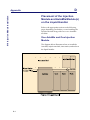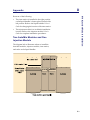
1
818 AutoMix
User’s Guide
LT2534/©2005 Gilson, Inc. All Rights Reserved.
May 2005
Table of Contents
1 Introduction
Unpacking . . . . . . . . . . . . . . . . . . . . . . . . . . . . . . . . . . . . . . . 1-2
Customer Service . . . . . . . . . . . . . . . . . . . . . . . . . . . . . . . . . 1-3
Technical Specifications . . . . . . . . . . . . . . . . . . . . . . . . . . . 1-4
2 Installation
AutoMix Setup . . . . . . . . . . . . . . . . . . . . . . . . . . . . . . . . . . .
Placement on the Liquid Handler . . . . . . . . . . . . . . . .
Installing the AutoMix’s Cover . . . . . . . . . . . . . . . . . .
Installing a Rack into the AutoMix . . . . . . . . . . . . . . .
2-2
2-2
2-4
2-4
Using Rear Panel Switches and Connectors . . . . . . . . . . 2-6
Speed Switch . . . . . . . . . . . . . . . . . . . . . . . . . . . . . . . . . 2-6
I.O. (Input/Output) Port . . . . . . . . . . . . . . . . . . . . . . . 2-6
Contact inputs . . . . . . . . . . . . . . . . . . . . . . . . . . . . . 2-7
Contact output . . . . . . . . . . . . . . . . . . . . . . . . . . . . 2-7
Making connections . . . . . . . . . . . . . . . . . . . . . . . . 2-7
Unit ID Selector . . . . . . . . . . . . . . . . . . . . . . . . . . . . . . . 2-9
GSIOC Port . . . . . . . . . . . . . . . . . . . . . . . . . . . . . . . . . . 2-10
Power Receptacle and Power Switch . . . . . . . . . . . . 2-11
DC power cord . . . . . . . . . . . . . . . . . . . . . . . . . . . 2-11
AC adapter . . . . . . . . . . . . . . . . . . . . . . . . . . . . . . . 2-11
Placing Racks onto the Liquid Handler’s Locator Plate 2-12
3 Operation
Status Panel . . . . . . . . . . . . . . . . . . . . . . . . . . . . . . . . . . . . . . 3-2
Using UniPoint™ System Software
with the 818 AutoMix . . . . . . . . . . . . . . . . . . . . . . . . . . . . . 3-3
4 Maintenance
Cleaning . . . . . . . . . . . . . . . . . . . . . . . . . . . . . . . . . . . . . . . . 4-2
5 Troubleshooting
Electrical Problems . . . . . . . . . . . . . . . . . . . . . . . . . . . . . . . 5-2
Rack Not Rotating or
NOT READY Light is Illuminated . . . . . . . . . . . . . . . 5-2
Input or Output Functions Not Operating . . . . . . . . 5-2
Repair and Return Policies . . . . . . . . . . . . . . . . . . . . . . . . .
Before calling us . . . . . . . . . . . . . . . . . . . . . . . . . . . . . .
Warranty repair . . . . . . . . . . . . . . . . . . . . . . . . . . . . . . .
Non-warranty repair . . . . . . . . . . . . . . . . . . . . . . . . . . .
Rebuilt exchange . . . . . . . . . . . . . . . . . . . . . . . . . . . . . .
Return procedure . . . . . . . . . . . . . . . . . . . . . . . . . . . . .
5-3
5-3
5-3
5-3
5-3
5-4
A Replacement Parts and Accessories
B Racks
C GSIOC Commands
GSIOC Commands . . . . . . . . . . . . . . . . . . . . . . . . . . . . . . . C-2
GSIOC Command List . . . . . . . . . . . . . . . . . . . . . . . . . C-2
D 819 Injection Module Installation
Placement of the Injection Module
and AutoMix Module(s) on the Liquid Handler . . . . . . . D-2
One AutoMix and One Injection Module . . . . . . . . . D-2
Two AutoMix Modules and One Injection Module . D-3
1
Introduction
The Gilson 818 AutoMix provides you with thorough mixing of your samples. It is used with
a single-probe Gilson 215 Liquid Handler.
Gilson 818 AutoMix
1-1
1
Introduction
Unpacking
Unpacking
After unpacking, ensure you have the following:
•
AutoMix module, DC power cord, GSIOC cable,
and terminal block connector
•
AutoMix cover (ordered separately)
If you also ordered the rack to be used in the AutoMix,
verify that it was supplied.
Promptly report any damage to the carrier. Some
carriers must receive concealed damage claims within
seven days of delivery.
Keep the original container(s) and packing material in
case the AutoMix must be returned to the factory.
1-2
Introduction
1
Customer Service
Customer Service
Gilson, Inc. and its worldwide network of authorized
representatives provide you with the following types
of assistance: sales, technical, applications, and
instrument repair.
If you need assistance and are in the United States
please contact your regional Gilson representative
or call the Gilson Customer Service Department at
800-445-7661 or 608-836-1551.
You can also contact the Gilson Customer Service
Department via its electronic mail (e-mail) address:
[email protected]. Outside the United States,
contact your Gilson representative for assistance.
Specific contact information can be found on the
Gilson website at www.gilson.com.
1-3
1
Introduction
Technical Specifications
Technical Specifications
Please be aware of the following before operating the
AutoMix.
Note: Changes or modifications to this device not
expressly approved by Gilson could void your
factory-authorized warranty.
This device has been tested and found to comply with
the limits for a Class A digital device, pursuant to Part
15 of the FCC commercial environment. This device
generates, uses, and can radiate radio frequency
energy and, if not installed and used in accordance
with the instructions, may cause harmful interference
to radio communications. Operation of this device in
a residential area is likely to cause harmful
interference, in which case you will be required to
correct the interference at your own expense.
Shielded cables must be used with this unit to ensure
compliance with the Class A FCC limits.
Technical Specification
Definition
Contact control
One contact closure output and two contact closure
inputs
Environmental
conditions
Indoor use
Altitude: up to 2000 m
Temperature range: 5-40°C
Air pressure: 75-105 kPa
Pollution degree: 1 or 2, in accordance with IEC 66
Humidity: Maximum relative humidity 80% for
temperatures up to 31°C, decreasing linearly to 50%
relative humidity at 40°C
Front panel
POWER light and NOT READY light
Liquid contact materials
Aluminum
Manufacturing standards
Meets applicable Safety and EMC certification
standards; UL and CE certified
1-4
1
Introduction
Low speed: 10 rpm, ±0.5 rpm accuracy
Number of racks
One Code 200-Series rack
Physical space
requirement
Fits on the single probe 215 Liquid Handler. Requires
two positions on the locator plate.
Power requirements
+24V DC at 1A supplied via a 2.1 mm ID power plug.
Center contact is positive.
Software control
Gilson Serial Input/Output Channel (GSIOC) and
UniPoint Software
Weight
5.3 kg (11.8 lbs)
High speed: 20 rpm, ±1 rpm accuracy
1-5
Technical Specifications
Mixing speeds and
accuracy
Installation
2
2-1
2
Installation
AutoMix Setup
AutoMix Setup
Placement on the Liquid Handler
To install the AutoMix, align the holes in the bottom
of the AutoMix with pins on the liquid handler’s
locator plate. Then lower the AutoMix into place.
On the following pages are example placement
diagrams for the AutoMix and racks. Be aware of the
following when installing the AutoMix.
2-2
•
The AutoMix occupies two rack positions on the
liquid handler’s locator plate.
•
The AutoMix cannot be placed in front of the rinse
station. You can move the rinse station to an
alternate location, if necessary.
•
If you are using two AutoMix modules, the
6-position locator plate (part number 25045513)
must be installed on the liquid handler and the
rinse station installed in the center location.
2
Installation
If you are using the 6-position locator plate and
install a rack in the far right or left position
(instead of an AutoMix), the liquid handler’s
probe will not be able to access all of the rack’s
tubes.
•
If using the AutoMix with a 819 Injection Module,
refer to Appendix D, 819 Injection Module
Installation for placement information.
Placing AutoMix on
5-position locator plate
AutoMix Setup
•
Placing two AutoMix modules
on 6-position locator plate
2-3
2
Installation
AutoMix Setup
Installing the AutoMix’s Cover
Secure the cover using the four latches located on the
AutoMix. The rack cover should be oriented with the
magnets to the back. Ensure that the latch pins go
through the holes located on the sides of the cover.
Note: If the cover is not installed, the AutoMix will not
rotate the rack.
Installing a Rack into the AutoMix
The AutoMix accepts one Code 200-Series rack (valid
rack codes are listed on page 2-5.
To install the rack:
2-4
1
Release the AutoMix’s cover by pulling the front
two latch knobs and then raise the front end of the
cover.
2
With the rack’s code number facing forward,
lower the rack into the AutoMix. Align the holes
on the underside of the rack with the pins on the
AutoMix.
Installation
Secure the AutoMix’s cover, making sure the latch
pins secure the cover into place.
4
Ensure that the holes in the cover have the same
pattern as the tube positions in the rack. If they do
not, install a different cover. Use cover
(part number 25052037) if a Code 200, 202, 203,
206, 209, 212, or 214 rack is installed. Use cover
(part number 25052038) if a Code 207, 210, or 213
rack is installed. Use cover (part number
25052039) if a Code 204 rack is installed.
AutoMix Setup
3
2
2-5
2
Installation
Using Rear Panel Switches and Connectors
Using Rear Panel Switches and
Connectors
Refer to the diagram when using rear panel switches
and connectors.
I.O.
SPEED
HIGH
START/
HOME
EMERG.
STOP
POWER
ON
AT
HOME
LOW
GSIOC
UNIT I.D.
= 20+SETTING
3
4
0 1
5
6
2 3
7 89
2
OFF
4
1
+24 VDC
1AMP.
5 6
1
Speed switch
2
I.O. (input/output) port
3
Unit ID selector
4
Gilson Serial Input/Output Channel (GSIOC)
port
5
Power receptacle
6
Power switch
Speed Switch
Use the Speed switch to select how fast to rotate the
AutoMix’s rack. You can change the speed while the
AutoMix’s rack is rotating.
Low: 10 RPM, ± 0.5 RPM accuracy
High: 20 RPM, ± 1 RPM accuracy
I.O. (Input/Output) Port
Use the AutoMix’s input and output contacts to
receive signals from and send signals to other
instruments.
2-6
Installation
2
Using Rear Panel Switches and Connectors
Contact inputs
The AutoMix has two contact closure inputs,
Start/Home and Emergency Stop. An input contact is
connected if it has a short across the input or is held
low (closed) by a TTL output or other device. Never
connect voltages higher than 5V DC to an input.
When using TTL signals, be sure to match GROUND
( ) connections.
When using the Start/Home input, a short that causes
the input to go from a closed to open state will home
the rack. A short that causes the input to go from an
open to closed state will start rotation of the rack.
Since an input is normally open, you have to close the
input then open it to home the rack. Then close the
input again to start rotating the rack. The rack will not
start rotating unless it has been moved to the home
position.
Gilson recommends that you connect the Emergency
Stop input to output contact 1, 2, or 3 of the liquid
handler. Then define the output contact as the
emergency contact in the 215 Setup Utility program.
See the liquid handler’s User’s Guide for more
information on the 215 Setup Utility program.
Contact output
The AutoMix has one contact closure output, At
Home. The output is an isolated-relay contact closure.
This contact will close when the AutoMix’s rack is
stopped at the home position.
Making connections
Before making power connections, ensure that power
is turned off to the AutoMix and the peripheral
instrument (for example, 215 Liquid Handler).
To make contact connections, you need the following:
•
2-conductor cable (22 - 30 gauge for each wire)
2-7
2
Using Rear Panel Switches and Connectors
Installation
•
wire insulation stripper
•
small-blade screwdriver
You can purchase a 6-foot piece of suitable cable
(part number 709910206) from Gilson.
To prepare and make connections with the
2-conductor cable:
2-8
1
Cut the cable into pieces of appropriate length.
2
Strip about 1.1 cm of insulation from each end of
the cable.
3
Locate the terminal block connector in the
AutoMix’s accessory package.
4
Insert each wire into the appropriate slot on the
connector. Push the wire all the way in; then
tighten its corresponding pin screw.
5
Connect the terminal block connector to the
AutoMix. Push the terminal connector in as far as
it will go. It is designed to fit snugly into its
receptacle.
6
Connect the opposite ends of the wires to the other
device. Be sure to match GROUND connections.
7
Label each cable to identify the purpose of the
connection.
Installation
2
Using Rear Panel Switches and Connectors
Unit ID Selector
At the factory, Gilson set the AutoMix’s unit ID to 28.
The unit ID identifies the AutoMix to Gilson software
packages that can issue GSIOC commands. There is
no need to change the unit ID unless there are two
AutoMix modules installed on the same liquid
handler. In that case, you must change the unit ID of
one of the modules.
To change the unit ID:
1
Gently insert a small flat blade screwdriver into
the Unit ID selector on the rear panel and turn it.
2
Align the white dot with one of the indicated
numbers. The unit ID is 20 plus the selected
number.
2-9
2
Installation
Using Rear Panel Switches and Connectors
GSIOC Port
Use the GSIOC port to connect the AutoMix to the 215
Liquid Handler. This enables the AutoMix to be
controlled via a program running on the keypad or
computer connected to the liquid handler.
2-10
1
Locate the GSIOC cable in the AutoMix’s
accessory package.
2
Connect one of the female connectors to the
GSIOC port of the AutoMix. Tighten the retaining
screws.
3
Connect the other female connector to the GSIOC
port of the liquid handler.
4
Use the male connector to connect another GSIOC
cable if multiple Gilson instruments (such as two
AutoMix modules) are being controlled via the
liquid handler. Refer to the diagram below.
Installation
2
Using Rear Panel Switches and Connectors
Power Receptacle and Power
Switch
Before making the power connection, ensure that
power is turned off to the AutoMix and the 215 Liquid
Handler.
DC power cord
Use the DC power cord, supplied with the AutoMix,
to make the connection between the AutoMix’s +24V
DC power receptacle and the 215 Liquid Handler’s
+24V DC output. When making the connection to the
liquid handler, connect the white cable to the +24V
DC output and the black cable to GND ( ).
To supply power to the AutoMix, turn ON power to
the liquid handler and then to the AutoMix using
their power switches.
AC adapter
If two AutoMix modules are installed, use an AC
adapter (part number 25045518), available from
Gilson, to connect the second AutoMix to a power
outlet.
To supply power to the AutoMix, use its power
switch.
2-11
Installation
2
Placing Racks onto the Liquid Handler’s Locator Plate
Placing Racks onto the Liquid
Handler’s Locator Plate
To raise the racks installed on the liquid handler’s
locator plate to the same level as the rack installed in
the AutoMix, place an RH1 rack heightener
(part number 25045514) beneath each of the racks.
2-12
Operation
3
The 818 AutoMix is controlled as follows:
•
Via a method running on a personal computer and controlling the liquid handler. You
create the method using UniPoint™ System Software.
•
Via an executable file running on a Gilson Keypad Controller to control the liquid handler.
If you have not already done so, install the UniPoint™ System Software. Refer to the User's
Guide included with the software.
Caution! Before operating the AutoMix, ensure that its cover is secure.
Caution! Do not touch the AutoMix while it is rotating its rack.
3-1
3
Operation
Status Panel
Status Panel
The status panel of the AutoMix contains a POWER
light and NOT READY light.
The POWER light becomes lit whenever it receives
power via the DC power cord connection to the 215
Liquid handler (the liquid handler must be powered
ON) or via the AC adapter connection to a power
outlet.
The NOT READY light becomes lit if an error is
detected. An error condition can be caused by the
AutoMix’s cover not being in place or if the AutoMix’s
rack is not in the home (upright) position.
3-2
Operation
3
Using UniPoint™ System Software with the 818 AutoMix
Using UniPoint™ System
Software with the 818 AutoMix
The following instructions explain how to use
UniPoint to send contact signals to the 818 AutoMix.
For more information, refer to the UniPoint System
Software User’s Guide.
1
Open a Control Method.
2
In the Device menu, select Contacts.
3
Select the contact in the Devices dialog box that
corresponds with the contact on the 506C System
Interface Module that is connected to the
INPUT/OUTPUT port on the 818 AutoMix.
3-3
3
Using UniPoint™ System Software with the 818 AutoMix
Operation
Enter a description for that device. For more
information on making contact connections, refer
to Chapter 2, Installation.
4
Click OK to add the description to the device.
Click OK again to exit the Contact dialog box.
5
In the Event menu, select Contact.
6
Highlight the device description that you created
in step 3. Enter the time for the event (either
contact open or contact close) to occur.
In the Action dialog box, choose open or close to
activate the contact at the time specified.
The AutoMix has two contact closure inputs,
Start/Home and Emergency Stop. When using
the Start/Home input, opening the contact homes
the rack. Closing the contact will start the rotation
of the rack. Since an input is normally open, you
3-4
Operation
3
Using UniPoint™ System Software with the 818 AutoMix
have to close the input then open it to home the
rack. Then close the input again to start rotating
the rack. The rack will not rotate unless it has been
moved to the home position.
The AutoMix has one contact closure output, At
Home. This contact will close when the AutoMix’s
rack is stopped at the home position.
7
Click on Insert to add the event to the open control
method. Click on Done to return to the Control
Method screen.
8
Before running the method, ensure that all
electrical connections have been made and the
power switch on the 818 AutoMix is switched to
the on position.
3-5
Maintenance
4
The AutoMix requires minimal maintenance. If a large spill occurs within the AutoMix, follow
the procedure to clean the AutoMix.
4-1
4
Maintenance
Cleaning
Cleaning
4-2
1
Remove the AutoMix’s cover. Wipe off if
necessary.
2
Remove the installed rack. Wipe off if necessary.
3
Wipe up any spilled liquid inside the AutoMix.
4
Remove the screw inside each of the safety stops
and then remove the front cover.
5
Remove the front idler and its washer by
removing the three front idler screws.
Maintenance
Remove the three drive hub screws.
7
Remove the cradle assembly from inside the
AutoMix.
8
Remove the drive hub and wipe off.
9
Re-assemble the AutoMix by reversing the above
steps.
Cleaning
6
4
4-3
Troubleshooting
5
5-1
5
Troubleshooting
Electrical Problems
Electrical Problems
Rack Not Rotating or NOT READY
Light is Illuminated
•
Ensure that the AutoMix’s cover is secure.
•
Ensure that the AutoMix’s rack is in the home
(upright) position.
•
Ensure that power is being supplied to the
AutoMix.
•
Determine if the AutoMix’s emergency stop input
has been activated by a peripheral device. If the
input is connected to a 215 Liquid Handler and the
liquid handler’s emergency output has been
activated, you must reset the emergency output.
Use the 215 Contact Test Utility, supplied with the
215 Setup Utility Programs that are supplied with
the liquid handler, to change the output to its
non-emergency state.
Input or Output Functions Not
Operating
5-2
•
Make sure connections into terminal block
connector are secure.
•
Make sure terminal block connector is secure in
the input/output port.
•
Check connections for proper pin assignments.
•
Check polarity of input to the AutoMix. Inputs
should be a contact closure. If not, it must be TTL
level (logic Ø activates).
•
Ensure that output from AutoMix is compatible
with the instrument to which it is interfaced.
Outputs are contact closures.
•
Confirm that the instrument connected to
AutoMix is working properly.
Troubleshooting
5
Repair and Return Policies
Repair and Return Policies
Before calling us
Gilson Customer Service personnel will be able to
serve you more efficiently if you have the following
information:
•
the serial number, located on the rear panel of the
AutoMix, and model number of the instruments
involved.
•
the installation procedure you used
•
list of concise symptoms
•
list of operating procedures and conditions you
were using when the problem arose
•
list of other devices connected to the fraction
collector and a description of those connections
•
list of other electrical connections in the room
Warranty repair
Units covered under warranty will be repaired and
returned to you at no charge. If you have any
questions about applicability, please contact Gilson or
your authorized representative.
Non-warranty repair
For out-of-warranty repairs, contact your local Gilson
representative or the Gilson Customer Service
Department. A Customer Service representative will
discuss service options with you and can assist in
making arrangements to return the equipment, if
necessary.
Rebuilt exchange
For some units, rebuilt exchange components are
available. Contact Gilson for details.
5-3
5
Troubleshooting
Repair and Return Policies
Return procedure
In the United States, contact the Gilson Customer
Service Department to obtain authorization before
returning any Gilson equipment. To return a piece of
equipment:
•
Carefully pack the unit to prevent damage in
transit. Check with Gilson regarding proper
method of shipment. No responsibility is assumed
by Gilson for damage caused by improperly
packaged instruments. Indicate the authorization
on the carton and on the packing slip.
•
Always insure for the replacement value of the
unit.
•
Include a description of symptoms, your name,
address, phone number, and purchase order to
cover repair costs, return and shipping charges, if
your institution requires it. Ship to:
Gilson, Inc.
Attention: Customer Service
(indicate the authorization here)
3000 W. Beltline Highway
Middleton, WI 53562
Outside the United States, contact your Gilson
representative for return procedures.
5-4
Replacement Parts and Accessories
A
Rack Accessories
For part numbers for available racks, refer to Appendix B, Racks.
Part Number
Description
25052037
Automix cover (magnetic) for code 207, 210 and 213
racks (regular pattern) for machines with serial
numbers after 250H0B001.
25052038
Automix cover (magnetic) for code 200, 202, 203, 206,
209, 212 and 214 rack (staggered pattern) for
machines with serial numbers after 250H0B001.
25052039
Automix cover (magnetic) for code 204 rack for
machines with serial numbers after 250H0B001.
25045514
RH1 215 Rack Heightener (4.8 cm). Required to raise
code 200-series racks to height of rack installed in 818
AutoMix.
Miscellaneous
25045513
6-position locator plate for installing two AutoMix
modules onto 215 Liquid Handler
250455191
819 locator plate for installing 819 Injection Module if
two AutoMix modules are installed on the 215
Liquid Handler
A-1
A
Replacement Parts and Accessories
Appendix
Miscellaneous
25045518
AC adapter for 818 AutoMix. Required to install two
818 AutoMix modules on 215 Liquid Handler.
7080200136
DC power cord
709910206
2-conductor interconnect wire, 6' length, for making
contact connections
36078143
Shielded GSIOC cable, 30" length
A-2
Racks
B
The 818 AutoMix can be configured with a several rack types and sizes. The following pages
describe the racks that can be purchased for use with the AutoMix. Refer to Chapter 2,
Installation for rack installation procedures.
B-1
B
Appendix
Racks
Code 200 rack
For 96 VacuTainer tubes
Material: aluminum
Vessels and maximum capacity: 13 x 100 mm (9 ml)
Part Number: 2504600
Code 202 rack
For 96 VacuTainer tubes
Material: aluminum
Vessels and maximum capacity: 10.25 x 47 mm (2.5 ml)
Part Number: 2504602
Code 203 rack
For 96 VacuTainer tubes
Material: aluminum
Vessels and maximum capacity: 10.25 x 64 mm (4 ml)
Part Number: 2504603
B-2
Appendix
B
Racks
Code 204 rack
For 27 scintillation tubes
Material: aluminum
Vessels and maximum capacity: 28 x 57 mm (20 ml)
Part Number: 2504604
Code 206 rack
For 96 VacuTainer tubes
Material: aluminum
Vessels and maximum capacity: 13 x 75 mm (7 ml)
Part Number: 2504606
Code 207 rack
For 75 VacuTainer tubes
Material: aluminum
Vessels and maximum capacity: 16 x 100 mm (12 ml)
Part Number: 2504607
B-3
B
Appendix
Racks
Code 209 rack
For 96 vessels
Material: aluminum
Vessels and maximum capacity: 12 x 32 mm
Part Number: 2504609
Code 210 rack
For 75 Vacutainer tubes
Material: aluminum
Vessels and maximum capacity: 16 x 75 mm (25 ml)
Part Number: 2504610
B-4
B
Appendix
Racks
Code 212 rack
For 96 VacuTainer tubes
Material: aluminum
Vessels and maximum capacity:
48 13 x 100 mm
(9 ml)
48 13 x 75 mm (7 ml)
Part Number: 2504612
Note: Place the shorter tubes into the notched tube
locations.
Code 213 rack
For 74 VacuTainer tubes
Material: aluminum
Vessels and maximum capacity:
37 16 x 100 mm
(32 ml)
37 16 x 75 mm
(25 ml)
Part Number: 2504613
Note: Place the shorter tubes into the notched tube
locations.
B-5
B
Racks
Code 214 rack
For 96 VacuTainer tubes
Material: aluminum
Vessels and maximum capacity:
48 10.25 x 47 mm
(2.5 ml)
48 10.25 x 64 mm
(44 ml)
Part Number: 2504614
Note: Place the shorter tubes into the notched tube
locations.
B-6
GSIOC Commands
C
The Gilson Serial Input Output Channel (GSIOC) is an asynchronous serial communications
interface that enhances the power of your Gilson equipment.
The GSIOC incorporates an EIA RS-485 interface and allows up to 32 slave devices to be
controlled from a master controller in a multi-drop configuration.
Each slave device is identified by a unique number that must be known to the device and to
the controller. The default ID code of the AutoMix is 28.
To control the AutoMix via the GSIOC interface, you need the following:
•
a computer with Microsoft Windows NT and any Gilson control software or 706 Device
Driver Software installed
•
506C System Interface or 215 Liquid Handler
From the controller, you:
•
specify the AutoMix as the device you want to control
•
issue commands that set operating parameters, control operation, or request information
from the Automix.
C-1
C
Appendix
GSIOC Commands
GSIOC Commands
There are two kinds of commands that you can send
over the GSIOC:
•
Buffered commands send instructions to the
AutoMix. These commands are executed one at a
time.
•
Immediate commands request status information
from the AutoMix. These commands are executed
immediately, temporarily interrupting other
commands in progress.
GSIOC Command List
In the command list below, the GSIOC command
must be entered in the proper upper or lower case
format. If a buffered command requires additional
information, you see italicized text next to the
command. The description of the command identifies
what you need to enter in place of the italicized text.
I - Immediate
B - Buffered
Command
Type
Description
%
I
Reads the current software version. Returns: 818va.bc where a.bc is
the currently installed version.
$
I
Resets the AutoMix. Equivalent to cycling power. $ is returned. Any
motion is stopped; motor is relaxed. Mixing mode is set to 1
(continuous turning in a clockwise direction).
The $ command can be used for emergency stop of the AutoMix.
The AutoMix will not accept any more commands after the sending
the immediate $ command until you manually move the rack to rest
at the horizontal position.
C-2
C
GSIOC Commands
Type
Description
E
I
Reads and returns error code:
00 -
No error
11 -
Cover is not closed
12 -
Home sensor for rack is not working
13 -
Rack position was lost while homing or
mixing
14 -
Emergency stop input is closed on powerup
GSIOC Commands
Command
Note: If the input is connected to a 215 Liquid Handler and the liquid
handler’s emergency output has been activated, you must reset the
emergency output. Use the 215 Contact Test Utility, supplied with
the 215 Setup Utility Programs that are supplied with the liquid
handler, to change the output to its non-emergency state.
Gs
B
Starts or stops rotation of rack depending on value of s:
R-
Starts rotation of rack
U-
Stops rotation of rack and unpowers motor;
rack is not homed; motor is relaxed (meaning
you can manually rotate the rack)
P-
Stops rotation of the rack and parks motor;
rack is not homed; motor is not relaxed
(meaning you cannot manually rotate the
rack)
Note: The AutoMix will not accept any more commands after the
sending the buffered GU command until you manually move the
rack to rest at the horizontal position.
G
I
Reads and returns motor status:
R-
Running
U-
Unpowered
P-
Parked
H
B
Homes AutoMix’s rack so it is in an upright position.
H
I
Reads position of AutoMix’s rack. Returns 1 if rack is in home
position. Returns 0 if it is not.
C-3
C
GSIOC Commands
Appendix
Command
Type
Description
I
I
Reads status of contact closures, Speed switch, and cover sensors. For
abcde, returns 0 or 1 where:
Mn
B
M
I
Sn
B
S
C-4
I
a-
1 (active) if Start/Home contact is closed, 0
(inactive) if open
b-
1 (active) if emergency stop contact is closed,
0 (inactive) if open
c-
1 if Speed switch is in the High position, 0 if
in the Low position
d-
1 if left sensor determines that the cover is
missing, 0 if cover is in place
e-
1 if right sensor determines that the cover is
missing, 0 if cover is in place
Sets the mixing motion. Indicate a value from 1 to 3 for n.
1-
continuous 360° rotation in
counterclockwise (CCW) direction; default
mixing motion
2-
continuous 360° rotation in clockwise (CW)
direction
3-
continuous rocking motion; 90° (± 20°) in
clockwise then counterclockwise direction
Reads and returns the code (1 - 3) that
identifies the mixing motion. See listing
above.
Sets the speed code which identifies how fast to mix. Indicate a value
from 2 to 5 for n.
2-
6.98 RPM
3-
9.60 RPM (default, equivalent to AutoMix’s
Speed switch in the Low position)
4-
15.36 RPM
5-
19.20 RPM (default, equivalent to AutoMix’s
Speed switch in the High position)
Reads and returns speed code. See listing on
previous page.
GSIOC Commands
C
Type
Description
Xnnn
B
Moves the AutoMix’s rack by a specified number of degrees. For
nnn, indicate a value from -360 to 360° (measured clockwise from the
front of the AutoMix).
X
I
Reads and returns current angle (0 to 359°) of the AutoMix’s rack. If
motor is unpowered, returns ???.
C-5
GSIOC Commands
Command
819 Injection Module Installation
D
D-1
Appendix
D
819 Injection Module Installation
Placement of the Injection
Module and AutoMix Module(s)
on the Liquid Handler
Refer to the appropriate section on the following
pages depending on whether you are installing the
injection module along with one or two AutoMix
modules.
One AutoMix and One Injection
Module
The diagram below illustrates where to install the
AutoMix, injection module, rinse station, and racks on
the liquid handler.
D-2
Appendix
D
•
The rinse station is installed in the right position
on the liquid handler’s locator plate, instead of the
left position. Refer to the liquid handler’s User’s
Guide for changing the location of the rinse station.
•
The injection module is in its default installation
location. Refer to the injection module’s User’s
Guide for complete installation procedures.
819 Injection Module Installation
Be aware of the following:
Two AutoMix Modules and One
Injection Module
The diagram below illustrates where to install the
AutoMix modules, injection module, rinse station,
and racks on the liquid handler.
D-3
819 Injection Module Installation
D
Placement of the Injection Module and AutoMix Module(s) on the Liquid Handler
Be aware of the following:
D-4
•
A 6-position locator plate (part number 25045513)
must be installed on the liquid handler.
•
The rinse station must be moved to and installed
in the center location. (The default location is left.)
•
The injection module is not installed in its default
location, next to right support of the liquid
handler. To install the injection module, you need
the 819 Locator Plate (part number 250455191).
Refer to the instructions included with the locator
plate to attach the injection module to the locator
plate and then to the 215 Liquid Handler.