1
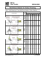
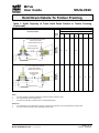
MiTek
User Guide
MIUG-0026
Hold Down Details To Timber Framing
Introduction
Details on this sheet provide fixing arrangements and capacities for hold-down
details to Timber Framing designed in MiTek software. Table 1 gives maximum
allowable uplift forces for each hold-down fixing arrangement to single, double and
triple truss heel joints.
Reading the Chart
1. Use MiTek software to design the truss and bracket fixing required based on
fixing arrangements listed in Table 1.
For further assistance with Hold down details to Timber Framing, contact
your nearest MiTek Engineering Design Office.
MiTek AUSTRALIA LTD.
A.C.N. 004 564 587
Page 1 of 3
Issue 4 16/05/08
MiTek
User Guide
MIUG-0026
Hold Down Details To Timber Framing
Table 1: Uplift Capacity of Truss Hold Down Details to Timber Framing
Uplift Capacity (kN)
J4
JD2/
JD3
JD4
JD5
JD6
MIUG26-1A
12 mm cup head
Bolt
-
-
10
-
16
11
8
MIUG26-1B
16 mm cup head
Bolt
M12 tie down rod
J3
20
15
-
20
-
-
-
MIUG26-2A
M12 Bolt
75 x 75 x 8 mm
angle bracket
J2
20
15
10
-
16
11
8
MIUG26-3A
M12 HS Bolt
Bolt through or above truss heel plate
with 12 mm cup head bolt for J4 &
JD4 to JD6 or 16 mm cup head bolt
for J2, J3 & JD2/JD3.
Joint Group
-
-
16
-
23
18
15
MIUG26-3B
M16 Bolt
50 x 50 x 3 mm
washer for M12 bolt
57 x 57 x 4 mm
washer for M16 bolt.
Fixing
Type
34
25
-
34
-
-
-
MIUG26-4A
M16 HS Bolt
Hold Down Details
49
44
28
49
44
36
28
Bolt through or above truss heel
plate with M12 bolt.
75 x 75 x 8 mm angle
brackets on both sides
of truss
M10 tie down rods
50 x 3 mm overstrap with M12 HS bolt for
J4, JD4 to JD6 or M16 bolt for J2, J3 and
JD2/JD3 through truss heel plate
50 x 10 mm
angle bracket
M16 tie down rod
50 x 3 mm overstrap with M16 HS bolt
through truss heel plate. Minimum
double 35 mm truss.
50 x 12 mm
angle bracket
M16 tie down rod
MiTek AUSTRALIA LTD.
A.C.N. 004 564 587
Page 2 of 3
Issue 4 16/05/08
MiTek
User Guide
MIUG-0026
Hold Down Details To Timber Framing
Table 1: Uplift Capacity of Truss Hold Down Details to Timber Framing
(Continued)
Uplift Capacity (kN)
Joint Group
Fixing
Type
J2
J3
J4
JD2/
JD3
JD4
JD5
JD6
MIUG26-5A
M16 HS Bolt
76
54
-
76
-
-
-
MIUG26-5B
M16 HS Bolt
Hold Down Details
-
-
34
-
54
43
34
50 x 3 mm overstrap with M16 HS bolt
through truss heel plate.
Minimum double 35 mm truss.
50 x 10 mm angle
brackets on both sides
M16 tie down rods
50 x 3 mm overstrap with M16 HS bolt
through truss heel plate.
Minimum triple 35 mm truss.
50 x 10 mm angle
brackets on both
sides
M16 tie down rods
Notes:
1.
For girder trusses in commercial buildings, multiply the design capacity by 0.85.
2.
HS – High strength steel bolt (Class 8.8).
3.
Overstrap must be tight or packed with non-compressible packing.
References:
1.
An Investigation of Truss Hold Down. TR No.44, James Cook University, Cyclone Testing Station October 1996.
2.
AS 1720.1 Timber Structures Code. Standards Australia 1997.
MiTek AUSTRALIA LTD.
A.C.N. 004 564 587
Page 3 of 3
Issue 4 16/05/08