1
Agilent Technologies
8360 B-Series Swept Signal Generator
(Including Options 001, 002, 004, 006, and 008)
User’s Guide
Serial Number Prefixes:
This manual applies directly to any swept signal generator with the
model and serial number prefix combination shown below. You may
have to modfiy this manual so that it applies directly to your
instrument version. Refer to the “Instrument History” chapter.
Agilent Technologies 83620B/22B/23B/24B/30B
3844A and Below
Agilent Technologies 83640B/50B
3844A and Below
Part No. 08360-90127
Printed in USA
May 2001
Supersedes March 2001
.
Notice
Restricted Rights
Legend
The information contained in this document is subject to change
without notice.
Agilent Technologies makes no warranty of any kind with regard to
this material, including but not limited to, the implied warranties
of merchantability and tness for a particular purpose. Agilent
Technologies shall not be liable for errors contained herein or
for incidental or consequential damages in connection with the
furnishing, performance, or use of this material.
Use, duplication, or disclosure by the U.S. Government is subject
to restrictions as set forth in subparagraph (c) (1) (ii) of the
Rights of Technical Data and Computer Software clause at DFARS
252.227-7013 for DOD agencies, and subparagraphs (c) (1) and
(c) (2) of the Commercial Computer Software Restricted Rights
clause at FAR 52.227-19 for other agencies.
c Copyright Agilent Technologies 1996, 1997, 1999, 2000, 2001
All Rights Reserved. Reproduction, adaptation, or translation
without prior written permission is prohibited, except as allowed
under the copyright laws.
1400 Fountaingrove Parkway, Santa Rosa, CA 95403-1799, USA
Certification
Warranty
Agilent Technologies certies that this product met its published
specications at the time of shipment from the factory. Agilent
Technologies further certies that its calibration measurements are
traceable to the United States National Institute of Standards and
Technology, to the extent allowed by the Institute's calibration
facility, and to the calibration facilities of other International
Standards Organization members.
This Agilent Technologies instrument product is warranted against
defects in material and workmanship for a period of one year from
date of shipment. During the warranty period, Agilent Technologies
will, at its option, either repair or replace products which prove to be
defective.
For warranty service or repair, this product must be returned
to a service facility designated by Agilent Technologies. Buyer
shall prepay shipping charges to Agilent Technologies and Agilent
Technologies shall pay shipping charges to return the product to
Buyer. However, Buyer shall pay all shipping charges, duties, and
taxes for products returned to Agilent Technologies from another
country.
Agilent Technologies warrants that its software and rmware
designated by Agilent Technologies for use with an instrument will
execute its programming instructions when properly installed on that
instrument. Agilent Technologies does not warrant that the operation
of the instrument, or software, or rmware will be uninterrupted or
error-free.
Limitation of Warranty
The foregoing warranty shall not apply to defects resulting from
improper or inadequate maintenance by Buyer, Buyer-supplied
software or interfacing, unauthorized modication or misuse,
operation outside of the environmental specications for the
product, or improper site preparation or maintenance.
NO OTHER WARRANTY IS EXPRESSED OR IMPLIED.
AGILENT TECHNOLOGIES SPECIFICALLY DISCLAIMS
THE IMPLIED WARRANTIES OF MERCHANTABILITY AND
FITNESS FOR A PARTICULAR PURPOSE.
Exclusive Remedies
THE REMEDIES PROVIDED HEREIN ARE BUYER'S SOLE
AND EXCLUSIVE REMEDIES. HEWLETT-PACKARD SHALL
NOT BE LIABLE FOR ANY DIRECT, INDIRECT, SPECIAL,
INCIDENTAL, OR CONSEQUENTIAL DAMAGES, WHETHER
BASED ON CONTRACT, TORT, OR ANY OTHER LEGAL
THEORY.
iii
Assistance
Safety Notes
iv
Product maintenance agreements and other customer assistance
agreements are available for Agilent Technologies products. For
any assistance, contact your nearest Agilent Technologies Sales and
Service Oce.
The following safety notes are used throughout this manual.
Familiarize yourself with each of the notes and its meaning before
operating this instrument.
WARNING
Warning denotes a hazard. It calls attention to a procedure which, if
not correctly performed or adhered to, could result in injury or loss
of life. Do not proceed beyond a warning note until the indicated
conditions are fully understood and met.
CAUTION
Caution denotes a hazard. It calls attention to a procedure that, if
not correctly performed or adhered to, would result in damage to or
destruction of the instrument. Do not proceed beyond a caution sign
until the indicated conditions are fully understood and met.
General Safety
Considerations
WARNING
No operator serviceable parts inside. Refer servicing to qualified
personnel. To prevent electrical shock, do not remove covers.
For continued protection against fire hazard replace line fuse only
with same type and rating (F 5A/250V). The use of other fuses or
material is prohibited.
This is a Safety Class I product (provided with a protective earthing
ground incorporated in the power cord). The mains plug shall only
be inserted in a socket outlet provided with a protective earth
contact. Any interruption of the protective conductor, inside or
outside the instrument, is likely to make the instrument dangerous.
Intentional interruption is prohibited.
If this instrument is used in a manner not specified by Agilent
Technologies, the protection provided by the instrument may be
impaired. This product must be used in a normal condition (in which
all means for protection are intact) only.
Position the instrument according to the enclosure protection
provided. This instrument does not protect against the ingress of
water. This instrument protects against finger access to hazardous
parts within the enclosure.
v
CAUTION
Note
vi
Before switching on this instrument, make sure that the line
voltage selector switch is set to the voltage of the power supply and
the correct fuse is installed.
Always use the three-prong ac power cord supplied with this
instrument. Failure to ensure adequate earth grounding by not
using this cord may cause instrument damage.
Before switching on this product, make sure that the line voltage
selector switch is set to the voltage of the power supply and
the correct fuse is installed. Assure the supply voltage is in the
specied range.
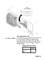
Ventilation Requirements: When installing the instrument in a
cabinet, the convection into and out of the instrument must not be
restricted. The ambient temperature (outside the cabinet) must be
less than the maximum operating temperature of the instrument
by 4 C for every 100 watts dissipated in the cabinet. If the total
power dissipated in the cabinet is greater than 800 watts, then
forced convection must be used.
This product is designed for use in Installation Category II and
Pollution Degree 2 per IEC 1010 and 664, respectively.
The detachable power cord is the instrument disconnecting device.
It disconnects the mains circuits from the mains supply before other
parts of the instrument. The front panel switch is only a standby
switch and is not a LINE switch.
PREFACE
Instruments Covered
By This Manual
This manual provides user information for the Agilent Technologies
8360 B-Series swept signal generator.
This manual applies to instruments having a serial number prex
listed on the title page (behind the \Documentation Map" tab).
Some changes may have to be made to this manual so that it
applies directly to each instrument; refer to Chapter 5, \Instrument
History", to see what changes may apply to your instrument.
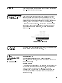
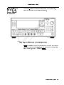
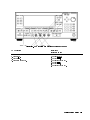
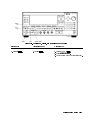
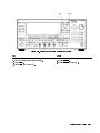
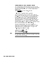
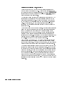
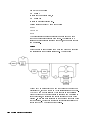
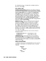
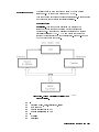
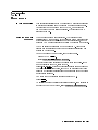
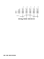
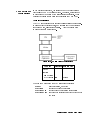
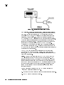
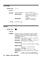
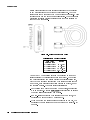
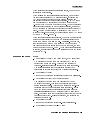
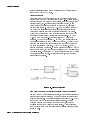
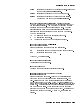
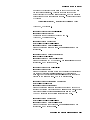
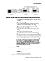
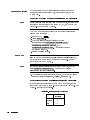
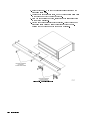
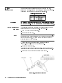
A serial number label (Figure 0-1) is attached to the instrument's
rear panel. A prex (four digits followed by a letter), and a sux
(ve digits unique to each instrument), comprise the instrument
serial number.
Figure 0-1.
Typical Serial Number Label
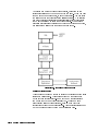
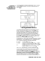
Organization
Tabs divide the major chapters of this manual. The contents of each
chapter is listed in the Table of Contents.
Agilent
Documentation Map
User's Guide
Technologies 8360
B-Series
Documentation
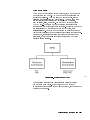
For a pictorial representation of the Agilent Technologies
8360 B-Series documentation, see the \Documentation Map" at the
front of this manual.
Ordering Manuals
A manual part number is listed on the title page of this manual. You
may use it to order extra copies of this manual. See \Replaceable
Parts" in Agilent Technologies 8360 B-Series Swept Signal
Generator/8360 L-Series Swept CW Generator Service Guide for
a complete list of Agilent Technologies 8360 documentation and
ordering numbers.
vii
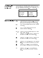
Typeface
Conventions
The following conventions are used in the Agilent Technologies
8360 B-Series documentation:
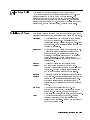
Italics Italic type is used for emphasis, and for titles of manuals and
other publications.
Computer Computer type is used for information displayed on the
instrument. For example: In this sequence, POWER LEVEL is displayed.
4
5 Instrument keys are represented in \key cap." You are
instructed to press a hardkey.
Softkeys Softkeys are located just below the display, and their
functions depend on the current display. These keys are represented
in \softkey." You are instructed to select a softkey.
Hardkeys
NNNNNNNNNNNNNNNNNNNNNNNNNN
Regulatory
Information
viii
This product has been designed and tested in accordance with IEC
Publication 1010, Safety Requirements for Electronic Measuring
Apparatus, and has been supplied in a safe condition. The
instruction documentation contains information and warnings
which must be followed by the user to ensure safe operation and to
maintain the instrument in a safe condition.
Manufacturer's
Declaration
Note
This is to certify that this product meets the radio frequency
interference requirements of Directive FTZ 1046/1984. The German
Bundespost has been notied that this equipment was put into
circulation and has been granted the right to check the product type
for compliance with these requirements.
Note: If test and measurement equipment is operated with
unshielded cables and/or used for measurements on open set-ups, the
user must insure that under these operating conditions, the radio
frequency interference limits are met at the border of his premises.
Model Agilent Technologies 8360 B-Series swept signal generator
Note
Hiermit wird bescheinigt, dass dieses Gerat/System in
U bereinstimmung mit den Bestimmungen von Postverfugung 1046/84
funkentst"rt ist.
Der Deutschen Bundespost wurde das Inverkehrbringen dieses
Gerates/Systems angezeight und die Berechtigung zur U berprufung
der Serie auf Einhaltung der Bestimmungen eingeraumt.
Zustzinformation fur Mess-und Testgerate:
Werden Mess- und Testgerate mit ungeschirmten Kabeln und/oder
in oenen Messaufbauten verwendet, so ist vom Betreiber
sicherzustellen, dass die Funk-Entst"rbestimmungen unter
Betriebsbedingungen an seiner Grundstucksgrenze eingehalten
werden.
ix
Declaration of
Conformity
x
Compliance with
German Noise
Requirements
This is to declare that this instrument is in conformance with the
German Regulation on Noise Declaration for Machines (Laermangabe
nach der Maschinenlaermrerordnung 03.GSGV Deutschland).
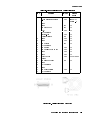
Acoustic Noise Emission/Geraeuschemission
Instrument Markings
L
LpA <70 dB
LpA <70 dB
Operator position
am Arbeitsplatz
Normal position
normaler Betrieb
per ISO 7779
nach DIN 45635 t.19
The instruction documentation symbol. The product is
marked with this symbol when it is necessary for the
user to refer to the instructions in the documentation.
The CE mark is a registered trademark of the European
Community.
The CSA mark is a registered trademark of the
Canadian Standards Association.
\ISM1-A" This is a symbol of an Industrial Scientic and Medical
Group 1 Class A product.
This is an ON symbol. The symbol ON is used to mark
the position of the instrument power line switch.
This is an ON symbol. The symbol ON is used to mark
the position of the instrument power line switch.
This is a STANDBY symbol. The STANDBY symbol is
used to mark the position of the instrument power line
switch.
This is an OFF symbol. The OFF symbol is used to
mark the position of the instrument power line switch.
This is an AC symbol. The AC symbol is used to
indicate the required nature of the line module input
power.
xi
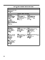
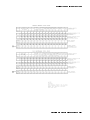
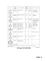
Table 0-1. Agilent Technologies Sales and Service Offices
UNITED STATES
Instrument Support Center
Agilent Technologies
(800) 403-0801
Headquarters
Agilent Technologies S.A.
150, Route du Nant-d'Avril
1217 Meyrin 2/Geneva
Switzerland
(41 22) 780.8111
Great Britain
EUROPEAN FIELD OPERATIONS
France
Germany
Agilent Technologies France
1 Avenue Du Canada
Zone D'Activite De Courtaboeuf
F-91947 Les Ulis Cedex
France
(33 1) 69 82 60 60
Agilent Technologies GmbH
Agilent Technologies Strasse
61352 Bad Homburg v.d.H
Germany
(49 6172) 16-0
Agilent Technologies Ltd.
Eskdale Road, Winnersh Triangle
Wokingham, Berkshire RG41 5DZ
England
(44 118) 9696622
Headquarters
Agilent Technologies
3495 Deer Creek Road
Palo Alto, California, USA
94304-1316
(650) 857-5027
Agilent Technologies Australia Ltd.
31-41 Joseph Street
Blackburn, Victoria 3130
(61 3) 895-2895
Agilent Technologies (Canada) Ltd.
17500 South Service Road
Trans-Canada Highway
Kirkland, Quebec H9J 2X8
Canada
(514) 697-4232
China
Japan
Singapore
China Agilent Technologies
38 Bei San Huan X1 Road
Shuang Yu Shu
Hai Dian District
Beijing, China
(86 1) 256-6888
Taiwan
Agilent Technologies Taiwan
8th Floor, H-P Building
337 Fu Hsing North Road
Taipei, Taiwan
(886 2) 712-0404
xii
INTERCON FIELD OPERATIONS
Australia
Canada
Agilent Technologies Japan, Ltd.
9-1 Takakura-Cho, Hachioji
Tokyo 192, Japan
(81 426) 60-2111
Agilent Technologies Singapore (Pte.) Ltd.
150 Beach Road
#29-00 Gateway West
Singapore 0718
(65) 291-9088
Contents
1. Getting Started
What Is In This Chapter . . . . . . . . . . . .
How To Use This Chapter . . . . . . . . . . . .
Equipment Used In Examples . . . . . . . . .
Introducing the Agilent 8360 B-Series Swept Signal
Generators . . . . . . . . . . . . . . . . .
Display Area . . . . . . . . . . . . . . . . . .
Entry Area . . . . . . . . . . . . . . . . . .
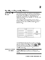
CW Operation and Start/Stop Frequency Sweep . .
CW Operation . . . . . . . . . . . . . . . .
Start/Stop Frequency Sweep . . . . . . . . . .
Center Frequency/Span Operation . . . . . . . .
Power Level and Sweep Time Operation . . . . . .
Power Level Operation . . . . . . . . . . . .
Sweep Time Operation . . . . . . . . . . . .
Continuous, Single, and Manual Sweep Operation .
Marker Operation . . . . . . . . . . . . . . .
Saving and Recalling an Instrument State . . . . .
Power Sweep and Power Slope Operation . . . . .
Power Sweep Operation . . . . . . . . . . . .
Power Slope Operation . . . . . . . . . . . .
Getting Started Advanced . . . . . . . . . . . .
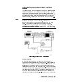
Externally Leveling the Swept Signal Generator . .
Leveling with Detectors/Couplers /Splitters . . .
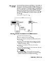
External Leveling Used With the Optional Step
Attenuator . . . . . . . . . . . . . . .
Leveling with Power Meters . . . . . . . . . .
Leveling with MM-wave Source Modules . . . . .
Working with Mixers/Reverse Power Eects . . . .
Working with Spectrum Analyzers/Reverse Power
Eects . . . . . . . . . . . . . . . . . . .
Optimizing Swept Signal Generator Performance . .
Creating and Applying the User Flatness Correction
Array . . . . . . . . . . . . . . . . . .
Creating a User Flatness Array Automatically,
Example 1 . . . . . . . . . . . . . . .
Creating a User Flatness Array, Example 2 . .
Swept mm-wave Measurement with Arbitrary
Correction Frequencies, Example 3 . . . .
Scalar Analysis Measurement with User Flatness
Corrections, Example 4 . . . . . . . . .
Using Detector Calibration . . . . . . . . . .
1-1
1-2
1-2
1-3
1-4
1-5
1-6
1-6
1-6
1-8
1-10
1-10
1-10
1-12
1-14
1-16
1-18
1-18
1-19
1-21
1-23
1-23
1-26
1-27
1-28
1-30
1-32
1-33
1-33
1-34
1-36
1-39
1-43
1-47
Contents-1
Using the Tracking Feature . . . . . .
Peaking . . . . . . . . . . . . . .
Tracking . . . . . . . . . . . . .
ALC Bandwidth Selection . . . . . . . .
Using Step Sweep . . . . . . . . . . .
Creating and Using a Frequency List . . .
Using the Security Features . . . . . . .
Changing the Preset Parameters . . . . .
Getting Started Programming . . . . . .
GPIB General Information . . . . . . .
Interconnecting Cables . . . . . . . .
Instrument Addresses . . . . . . . . .
GPIB Instrument Nomenclature . . . .
Listener . . . . . . . . . . . . . .
Talker . . . . . . . . . . . . . . .
Controller . . . . . . . . . . . . .
Programming the Swept Signal Generator
GPIB Command Statements . . . . . .
Abort . . . . . . . . . . . . . . .
Remote . . . . . . . . . . . . . .
Local Lockout . . . . . . . . . . .
Local . . . . . . . . . . . . . . .
Clear . . . . . . . . . . . . . . .
Output . . . . . . . . . . . . . .
Enter . . . . . . . . . . . . . . .
Getting Started with SCPI . . . . . . .
Denitions of Terms . . . . . . . . . .
Standard Notation . . . . . . . . . .
Command Mnemonics . . . . . . .
Angle Brackets . . . . . . . . . . .
How to Use Examples . . . . . . . . .
Command Examples . . . . . . . .
Response Examples . . . . . . . . .
Essentials for Beginners . . . . . . . . .
Program and Response Messages . . .
Forgiving Listening and Precise Talking
Types of Commands . . . . . . . .
Subsystem Command Trees . . . . . .
The Command Tree Structure . . . .
Paths Through the Command Tree . .
Subsystem Command Tables . . . . . .
Reading the Command Table . . . .
More About Commands . . . . . . .
Query and Event Commands . . . .
Implied Commands . . . . . . . .
Optional Parameters . . . . . . .
Program Message Examples . . . . .
Parameter Types . . . . . . . . . .
Numeric Parameters . . . . . . .
Extended Numeric Parameters . . .
Discrete Parameters . . . . . . .
Contents-2
.
.
.
.
.
.
.
.
.
.
.
.
.
.
.
.
.
.
.
.
.
.
.
.
.
.
.
.
.
.
.
.
.
.
.
.
.
.
.
.
.
.
.
.
.
.
.
.
.
.
.
.
.
.
.
.
.
.
.
.
.
.
.
.
.
.
.
.
.
.
.
.
.
.
.
.
.
.
.
.
.
.
.
.
.
.
.
.
.
.
.
.
.
.
.
.
.
.
.
.
.
.
.
.
.
.
.
.
.
.
.
.
.
.
.
.
.
.
.
.
.
.
.
.
.
.
.
.
.
.
.
.
.
.
.
.
.
.
.
.
.
.
.
.
.
.
.
.
.
.
.
.
.
.
.
.
.
.
.
.
.
.
.
.
.
.
.
.
.
.
.
.
.
.
.
.
.
.
.
.
.
.
.
.
.
.
.
.
.
.
.
.
.
.
.
.
.
.
.
.
.
.
.
.
1-49
1-49
1-49
1-50
1-51
1-52
1-53
1-54
1-55
1-56
1-56
1-56
1-56
1-56
1-56
1-56
1-56
1-57
1-57
1-58
1-58
1-59
1-59
1-60
1-61
1-63
1-63
1-64
1-64
1-64
1-64
1-64
1-65
1-66
1-66
1-66
1-67
1-68
1-68
1-68
1-71
1-71
1-72
1-72
1-72
1-72
1-72
1-73
1-73
1-74
1-75
Boolean Parameters . . . . . . . . . . .
Reading Instrument Errors . . . . . . . . . .
Example Programs . . . . . . . . . . . . . .
Example Program . . . . . . . . . . . . .
Description . . . . . . . . . . . . . . .
Program Listing . . . . . . . . . . . . .
Program Comments . . . . . . . . . . .
Details of Commands and Responses . . . . . . .
In This Subsection . . . . . . . . . . . . . .
Program Message Syntax . . . . . . . . . . .
Subsystem Command Syntax . . . . . . . .
Common Command Syntax . . . . . . . . .
Response Message Syntax . . . . . . . . . . .
SCPI Data Types . . . . . . . . . . . . . .
Parameter Types . . . . . . . . . . . . . .
Numeric Parameters . . . . . . . . . . .
Extended Numeric Parameters . . . . . . .
Discrete Parameters . . . . . . . . . . .
Boolean Parameters . . . . . . . . . . .
Response Data Types . . . . . . . . . . . .
Real Response Data . . . . . . . . . . .
Integer Response Data . . . . . . . . . .
Discrete Response Data . . . . . . . . . .
String Response Data . . . . . . . . . . .
Programming Typical Measurements . . . . . . .
In This Subsection . . . . . . . . . . . . . .
Using the Example Programs . . . . . . . . .
Use of the Command Tables . . . . . . . . .
GPIB Check, Example Program 1 . . . . . . .
Program Comments . . . . . . . . . . . .
Local Lockout Demonstration, Example Program 2
Program Comments . . . . . . . . . . . .
Setting Up A Typical Sweep, Example Program 3
Program Comments . . . . . . . . . . . .
Queries, Example Program 4 . . . . . . . . . .
Program Comments . . . . . . . . . . . .
Saving and Recalling States, Example Program 5 .
Program Comments . . . . . . . . . . . .
Looping and Synchronization, Example Program 6
Program Comments . . . . . . . . . . . .
Using the *WAI Command, Example Program 7 .
Program Comments . . . . . . . . . . . .
Using the User Flatness Correction Commands,
Example Program 8 . . . . . . . . . . . .
Programming the Status System . . . . . . . . .
In This Subsection . . . . . . . . . . . . . .
General Status Register Model . . . . . . . . .
Condition Register . . . . . . . . . . . . .
Transition Filter . . . . . . . . . . . . . .
Event Register . . . . . . . . . . . . . . .
Enable Register . . . . . . . . . . . . . .
1-75
1-76
1-77
1-77
1-77
1-77
1-78
1-80
1-80
1-80
1-81
1-81
1-82
1-83
1-83
1-83
1-84
1-85
1-85
1-85
1-85
1-86
1-86
1-86
1-87
1-87
1-87
1-88
1-90
1-90
1-91
1-92
1-93
1-93
1-95
1-95
1-97
1-97
1-99
1-99
1-101
1-101
1-103
1-106
1-106
1-106
1-106
1-107
1-107
1-107
Contents-3
An Example Sequence . . . . . . . . . . .
Programming the Trigger System . . . . . . . . .
In This Subsection . . . . . . . . . . . . . .
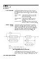
Generalized Trigger Model . . . . . . . . . . .
Overview . . . . . . . . . . . . . . . . .
Details of Trigger States . . . . . . . . . . .
Inside the Idle State . . . . . . . . . . .
Inside the Initiate State . . . . . . . . . .
Inside Event Detection States . . . . . . .
Inside the Sequence Operation State . . . .
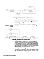
Common Trigger Congurations . . . . . . . .
The INIT Conguration . . . . . . . . . . .
The TRIG Conguration . . . . . . . . . .
Description of Triggering in the HP 8360 B-Series
Swept Signal Generators . . . . . . . . . .
Advanced Trigger Congurations . . . . . . .
Trigger Keyword Denitions . . . . . . . . . .
ABORt . . . . . . . . . . . . . . . . . .
IMMediate . . . . . . . . . . . . . . . .
ODELay . . . . . . . . . . . . . . . . .
SOURce . . . . . . . . . . . . . . . . . .
Related Documents . . . . . . . . . . . . . . .
The International Institute of Electrical and
Electronics Engineers. . . . . . . . . . . .
Hewlett-Packard Company . . . . . . . . . . .
2. Operating and Programming Reference
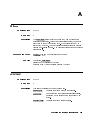
How To Use This Chapter . . . . . . . . . . . .
A.
Address . . . . . . . . . . . .
Adrs Menu . . . . . . . . . .
4
5 . . . . . . . . . . . . .
ALC Bandwidth Select Auto . .
ALC Bandwidth Select High . .
ALC Bandwidth Select Low . .
ALC BW Menu . . . . . . . . .
Altrnate Regs . . . . . . . .
AM BW Cal Always . . . . . .
AM BW Cal Once . . . . . . . .
AM Cal Menu . . . . . . . . .
AM Menu . . . . . . . . . . .
AM On/Off 10 dB/V . . . . . .
AM On/Off 100%/V . . . . . .
AM On/Off Ext . . . . . . . .
AM On/Off Int . . . . . . . .
Ampl Markers . . . . . . . . .
NNNNNNNNNNNNNNNNNNNNNNNNNNNNN
ALC
NNNNNNNNNNNNNNNNNNNNNNNNNNNNNNNNNNNNNNNNNNNNNNNNNNNNNNNNNNNNNNNNNNNNNNNNNNNNN
NNNNNNNNNNNNNNNNNNNNNNNNNNNNNNNNNNNNNNNNNNNNNNNNNNNNNNNNNNNNNNNNNNNNNNNNNNNNN
NNNNNNNNNNNNNNNNNNNNNNNNNNNNNNNNNNNNNNNNNNNNNNNNNNNNNNNNNNNNNNNNNNNNNNNNNN
NNNNNNNNNNNNNNNNNNNNNNNNNNNNNNNNNNN
NNNNNNNNNNNNNNNNNNNNNNNNNNNNNNNNNNNNNNNNN
NNNNNNNNNNNNNNNNNNNNNNNNNNNNNNNNNNNNNNNNNNNNNNNNNN
NNNNNNNNNNNNNNNNNNNNNNNNNNNNNNNNNNNNNNNNNNNN
NNNNNNNNNNNNNNNNNNNNNNNNNNNNNNNNNNN
NNNNNNNNNNNNNNNNNNNNNNN
NNNNNNNNNNNNNNNNNNNNNNNNNNNNNNNNNNNNNNNNNNNNNNNNNNNNN
NNNNNNNNNNNNNNNNNNNNNNNNNNNNNNNNNNNNNNNNNNNNNNNNNN
NNNNNNNNNNNNNNNNNNNNNNNNNNNNNNNNNNNNNNNNN
NNNNNNNNNNNNNNNNNNNNNNNNNNNNNNNNNNNNNNNNN
NNNNNNNNNNNNNNNNNNNNNNNNNNNNNNNNNNNNNN
Contents-4
.
.
.
.
.
.
.
.
.
.
.
.
.
.
.
.
.
.
.
.
.
.
.
.
.
.
.
.
.
.
.
.
.
.
.
.
.
.
.
.
.
.
.
.
.
.
.
.
.
.
.
.
.
.
.
.
.
.
.
.
.
.
.
.
.
.
.
.
.
.
.
.
.
.
.
.
.
.
.
.
.
.
.
.
.
.
.
.
.
.
.
.
.
.
.
.
.
.
.
.
.
.
.
.
.
.
.
.
.
.
.
.
.
.
.
.
.
.
.
.
.
.
.
.
.
.
.
.
.
.
.
.
.
.
.
.
1-107
1-109
1-109
1-109
1-109
1-110
1-111
1-111
1-112
1-114
1-115
1-115
1-116
1-117
1-118
1-118
1-118
1-118
1-118
1-119
1-120
1-120
1-120
2-1
A-1
A-1
A-3
A-10
A-10
A-11
A-11
A-12
A-13
A-13
A-14
A-14
A-15
A-16
A-16
A-17
A-18
. . . . . . .
. . . . . . .
ANALYZER STATUS REGISTER
Arrow Keys . . . . . . . . . .
4
5 . . . . . . . . . . . .
Auto Fill Incr . . . . . . . .
Auto Fill #Pts . . . . . . . .
Auto Fill Start . . . . . . .
Auto Fill Stop . . . . . . . .
Auto Track . . . . . . . . . .
.
.
.
.
.
.
.
.
.
.
A-18
A-19
A-20
A-22
A-23
A-24
A-25
A-26
A-27
A-28
. . . . . . . . . . . . . . . . . .
B-1
NNNNNNNNNNNNNNNNNNNNNNNNNNNNNNNNNNNNNNNNNNNNNNN
AM Type 10 dB/V
AM Type 100%/V .
NNNNNNNNNNNNNNNNNNNNNNNNNNNNNNNNNNNNNNNNNNNN
ASSIGN
NNNNNNNNNNNNNNNNNNNNNNNNNNNNNNNNNNNNNNNNNNNN
NNNNNNNNNNNNNNNNNNNNNNNNNNNNNNNNNNNNNNNNNNNN
NNNNNNNNNNNNNNNNNNNNNNNNNNNNNNNNNNNNNNNNNNNNNNN
NNNNNNNNNNNNNNNNNNNNNNNNNNNNNNNNNNNNNNNNNNNN
NNNNNNNNNNNNNNNNNNNNNNNNNNNNNNNN
B.
C.
NNNNNNNNNNNNNNNNNNNNNNNNNNNNNNNN
Blank Disp
. . . . .
Center=Marker .
Clear Fault . .
Clear Memory . .
Clear Point . .
CONNECTORS .
4
5
. . . . .
Copy List . . .
.
.
.
.
.
.
.
.
CorPair Disable .
Coupling Factor .
4 5
. . . . . . .
CW/CF Coupled . .
.
.
.
.
.
.
.
.
.
.
.
.
.
.
.
.
.
.
.
.
.
.
.
.
.
.
.
.
.
.
.
.
.
.
.
.
.
.
.
.
.
.
.
.
.
.
.
.
.
.
.
.
.
.
.
.
.
.
.
.
.
.
.
.
.
.
.
.
.
.
.
.
.
.
.
.
.
.
.
.
.
.
.
.
.
.
.
.
.
.
.
.
.
.
.
.
.
.
.
.
.
.
.
.
.
.
.
.
.
.
.
.
.
.
.
.
.
.
.
.
.
.
.
.
.
.
.
.
.
.
.
.
.
.
.
.
.
.
.
.
.
.
.
.
.
.
.
.
.
.
.
.
.
.
.
.
.
.
.
.
.
.
.
.
.
.
.
.
.
.
.
.
.
.
.
.
.
.
.
.
.
.
.
.
.
.
.
.
.
.
.
.
.
.
C-1
C-2
C-2
C-3
C-4
C-4
C-11
C-12
C-12
C-13
C-13
C-14
Dblr Amp Menu . . . .
Deep AM . . . . . . .
Delay Menu . . . . . .
Delete Menu . . . . .
Delete All . . . . . .
Delete Current . . . .
Delete Undef . . . . .
Delta Marker . . . . .
Delta Mkr Ref . . . .
Disp Status . . . . .
Doubler Amp Mode AUTO
Doubler Amp Mode Off
Doubler Amp Mode On .
Dwell Coupled . . . .
.
.
.
.
.
.
.
.
.
.
.
.
.
.
.
.
.
.
.
.
.
.
.
.
.
.
.
.
.
.
.
.
.
.
.
.
.
.
.
.
.
.
.
.
.
.
.
.
.
.
.
.
.
.
.
.
.
.
.
.
.
.
.
.
.
.
.
.
.
.
.
.
.
.
.
.
.
.
.
.
.
.
.
.
.
.
.
.
.
.
.
.
.
.
.
.
.
.
.
.
.
.
.
.
.
.
.
.
.
.
.
.
.
.
.
.
.
.
.
.
.
.
.
.
.
.
.
.
.
.
.
.
.
.
.
.
.
.
.
.
.
.
.
.
.
.
.
.
.
.
.
.
.
.
.
.
.
.
.
.
.
.
.
.
.
.
.
.
D-1
D-2
D-2
D-3
D-3
D-4
D-5
D-5
D-6
D-7
D-8
D-9
D-10
D-10
NNNNNNNNNNNNNNNNNNNNNNNNNNNNNNNNNNNNNNNNN
NNNNNNNNNNNNNNNNNNNNNNNNNNNNNNNNNNN
NNNNNNNNNNNNNNNNNNNNNNNNNNNNNNNNNNNNNN
NNNNNNNNNNNNNNNNNNNNNNNNNNNNNNNNNNN
CONT
NNNNNNNNNNNNNNNNNNNNNNNNNNNNN
NNNNNNNNNNNNNNNNNNNNNNNNNNNNNNNNNNNNNNNNNNNNNNN
NNNNNNNNNNNNNNNNNNNNNNNNNNNNNNNNNNNNNNNNNNNNNNN
CW
NNNNNNNNNNNNNNNNNNNNNNNNNNNNNNNNNNNNNNNNN
D.
.
.
.
.
.
.
.
.
.
.
.
.
.
.
.
.
.
.
.
.
.
.
4CENTER5
.
.
.
.
.
.
.
.
.
.
.
.
.
.
.
.
.
.
.
.
.
.
NNNNNNNNNNNNNNNNNNNNNNNNNNNNNNNNNNNNNNNNN
NNNNNNNNNNNNNNNNNNNNNNN
NNNNNNNNNNNNNNNNNNNNNNNNNNNNNNNN
NNNNNNNNNNNNNNNNNNNNNNNNNNNNNNNNNNN
NNNNNNNNNNNNNNNNNNNNNNNNNNNNNNNN
NNNNNNNNNNNNNNNNNNNNNNNNNNNNNNNNNNNNNNNNNNNN
NNNNNNNNNNNNNNNNNNNNNNNNNNNNNNNNNNNNNN
NNNNNNNNNNNNNNNNNNNNNNNNNNNNNNNNNNNNNN
NNNNNNNNNNNNNNNNNNNNNNNNNNNNNNNNNNNNNNNNN
NNNNNNNNNNNNNNNNNNNNNNNNNNNNNNNNNNN
NNNNNNNNNNNNNNNNNNNNNNNNNNNNNNNNNNNNNNNNNNNNNNNNNNNNNNNNNNNNNNNNN
NNNNNNNNNNNNNNNNNNNNNNNNNNNNNNNNNNNNNNNNNNNNNNNNNNNNNNNNNNNNNN
NNNNNNNNNNNNNNNNNNNNNNNNNNNNNNNNNNNNNNNNNNNNNNNNNNNNNNNNNNN
NNNNNNNNNNNNNNNNNNNNNNNNNNNNNNNNNNNNNNNNN
Contents-5
E.
8360 Adrs . . . .
Enter Corr . . . .
Enter Freq . . . .
Enter List Dwell
Enter List Freq .
Enter List Offset
.
.
.
.
.
.
ENTRY KEYS . . . .
4
5 . . . .
Ext Det Cal . . . .
.
.
.
.
.
.
.
.
.
.
.
.
.
.
.
.
.
.
.
.
.
.
.
.
.
.
.
.
.
.
.
.
.
.
.
.
.
.
.
.
.
.
.
.
.
.
.
.
.
.
.
.
.
.
.
.
.
.
.
.
.
.
.
.
.
.
.
.
.
.
.
.
.
.
.
.
.
.
.
.
.
.
.
.
.
.
.
.
.
.
.
.
.
.
.
.
.
.
.
.
.
.
.
.
.
.
.
.
.
.
.
.
.
.
.
.
.
E-1
E-2
E-3
E-4
E-4
E-5
E-5
E-6
E-6
Fault Menu .
Fault Info 1
Fault Info 2
Fault Info 3
Fltness Menu
.
.
.
.
.
.
.
.
.
.
.
.
.
.
.
.
.
.
.
.
.
.
.
.
.
.
.
.
.
.
.
.
.
.
.
.
.
.
.
.
.
.
.
.
.
.
.
.
.
.
.
.
.
.
.
.
.
.
.
.
.
.
.
.
.
.
.
.
.
.
.
.
.
.
.
.
.
.
.
.
.
.
.
.
.
.
.
.
.
.
.
.
.
.
.
.
.
.
.
.
.
.
.
.
.
.
.
.
.
.
.
.
.
.
.
.
.
.
.
.
.
.
.
.
.
.
.
.
.
.
.
.
.
.
.
.
.
.
.
.
.
.
.
.
.
.
.
.
.
.
.
.
.
.
.
.
.
.
.
.
.
.
.
.
.
.
.
.
.
.
.
.
.
.
.
.
.
.
.
.
.
.
.
.
.
.
.
.
.
.
.
.
.
.
.
.
.
.
.
.
.
.
.
.
.
.
.
.
.
.
.
.
.
.
.
.
.
.
.
.
.
.
.
.
.
.
.
.
.
.
.
.
.
.
.
.
.
.
.
.
.
.
.
.
.
.
.
F-1
F-2
F-3
F-4
F-5
F-10
F-11
F-11
F-12
F-13
F-13
F-14
F-15
F-16
F-16
F-17
F-18
F-19
F-20
. . . . . . . . . . . . . . . .
. . . . . . . . . . . . . . . .
G-1
G-1
NNNNNNNNNNNNNNNNNNNNNNNNNNNNN
NNNNNNNNNNNNNNNNNNNNNNNNNNNNNNNN
NNNNNNNNNNNNNNNNNNNNNNNNNNNNNNNN
NNNNNNNNNNNNNNNNNNNNNNNNNNNNNNNNNNNNNNNNNNNNNNNNNN
NNNNNNNNNNNNNNNNNNNNNNNNNNNNNNNNNNNNNNNNNNNNNNN
NNNNNNNNNNNNNNNNNNNNNNNNNNNNNNNNNNNNNNNNNNNNNNNNNNNNN
ENTRY ON/OFF
NNNNNNNNNNNNNNNNNNNNNNNNNNNNNNNNNNN
F.
NNNNNNNNNNNNNNNNNNNNNNNNNNNNNNNN
NNNNNNNNNNNNNNNNNNNNNNNNNNNNNNNNNNNNNN
NNNNNNNNNNNNNNNNNNNNNNNNNNNNNNNNNNNNNN
NNNNNNNNNNNNNNNNNNNNNNNNNNNNNNNNNNNNNN
NNNNNNNNNNNNNNNNNNNNNNNNNNNNNNNNNNNNNN
4FLTNESS
.
.
.
.
.
ON/OFF5
.
.
.
.
.
.
.
.
.
.
.
.
NNNNNNNNNNNNNNNNNNNNNNNNNNNNNNNNNNNNNNNNNNNNNNNNNNNNNNNN
FM Coupling 100kHz
FM Coupling DC . .
FM Menu . . . . .
FM On/Off AC . . .
FM On/Off DC . . .
FM On/Off Ext . .
FM On/Off Int . .
Freq Cal Menu . .
Freq Follow . . .
.
.
.
.
.
.
.
.
.
.
.
.
.
.
FREQUENCY 4 5 .
Freq Mult . . . . .
Freq Offset . . . .
FullUsr Cal . . . .
NNNNNNNNNNNNNNNNNNNNNNNNNNNNNNNNNNNNNNNNNNNN
NNNNNNNNNNNNNNNNNNNNNNN
NNNNNNNNNNNNNNNNNNNNNNNNNNNNNNNNNNNNNN
NNNNNNNNNNNNNNNNNNNNNNNNNNNNNNNNNNNNNN
NNNNNNNNNNNNNNNNNNNNNNNNNNNNNNNNNNNNNNNNN
NNNNNNNNNNNNNNNNNNNNNNNNNNNNNNNNNNNNNNNNN
NNNNNNNNNNNNNNNNNNNNNNNNNNNNNNNNNNNNNNNNN
NNNNNNNNNNNNNNNNNNNNNNNNNNNNNNNNNNN
NNNNNNNNNNNNNNNNNNNNNNNNNNNNN
MENU
NNNNNNNNNNNNNNNNNNNNNNNNNNNNNNNNNNN
NNNNNNNNNNNNNNNNNNNNNNNNNNNNNNNNNNN
G.
Global Dwell .
Global Offset
NNNNNNNNNNNNNNNNNNNNNNNNNNNNNNNNNNNNNN
NNNNNNNNNNNNNNNNNNNNNNNNNNNNNNNNNNNNNNNNN
Contents-6
H.
HP-IB Address . . . . . . . . . . . . . . . . .
HP-IB Menu . . . . . . . . . . . . . . . . . .
H-1
H-1
Internal AM Depth . . . . . . .
Internal AM Rate
. . . . . . .
Internal AM Waveform Noise . .
Internal AM Waveform Ramp . . .
Internal AM Waveform Sine . . .
Internal AM Waveform Square . .
Internal AM Waveform Triangle .
Internal FM Deviation . . . . .
Internal FM Rate
. . . . . . .
Internal FM Waveform Noise . .
Internal FM Waveform Ramp . . .
Internal FM Waveform Sine . . .
Internal FM Waveform Square . .
Internal FM Waveform Triangle .
Internal Menu . . . . . . . . .
Internal Pulse Generator Period
Internal Pulse Generator Rate .
Internal Pulse Generator Width
Internal Pulse Mode Auto . . .
Internal Pulse Mode Gate . . .
Internal Pulse Mode Trigger . .
Invert Input . . . . . . . . . .
.
.
.
.
.
.
.
.
.
.
.
.
.
.
.
.
.
.
.
.
.
.
.
.
.
.
.
.
.
.
.
.
.
.
.
.
.
.
.
.
.
.
.
.
.
.
.
.
.
.
.
.
.
.
.
.
.
.
.
.
.
.
.
.
.
.
.
.
.
.
.
.
.
.
.
.
.
.
.
.
.
.
.
.
.
.
.
.
.
.
.
.
.
.
.
.
.
.
.
.
.
.
.
.
.
.
.
.
.
.
.
.
.
.
.
.
.
.
.
.
.
.
.
.
.
.
.
.
.
.
.
.
.
.
.
.
.
.
.
.
.
.
.
.
.
.
.
.
.
.
.
.
.
.
I-1
I-2
I-2
I-3
I-3
I-4
I-4
I-5
I-5
I-6
I-6
I-7
I-7
I-8
I-8
I-9
I-10
I-10
I-11
I-11
I-12
I-12
. . . .
. . . .
. . . .
. . .
. . .
. . .
. . .
LINE SWITCH . . . . . . .
List Menu . . . . . . . . .
List Mode Pt TrigAuto . . .
List Mode Pt TrigBus . . .
List Mode Pt TrigExt . . .
4
5 . . . . . . . . . . .
.
.
.
.
.
.
.
.
.
.
.
.
.
.
.
.
.
.
.
.
.
.
.
.
.
.
.
.
.
.
.
.
.
.
.
.
.
.
.
.
.
.
.
.
.
.
.
.
.
.
.
.
.
.
.
.
.
.
.
.
.
.
.
.
.
.
.
.
.
.
.
.
.
.
.
.
.
.
.
.
.
.
.
.
.
.
.
.
.
.
.
L-1
L-2
L-2
L-3
L-3
L-4
L-5
L-5
L-6
L-8
L-9
L-9
L-10
NNNNNNNNNNNNNNNNNNNNNNNNNNNNNNNN
I.
NNNNNNNNNNNNNNNNNNNNNNNNNNNNNNNNNNNNNNNNNNNNNNNNNNNNN
NNNNNNNNNNNNNNNNNNNNNNNNNNNNNNNNNNNNNNNNNNNNNNNNNN
NNNNNNNNNNNNNNNNNNNNNNNNNNNNNNNNNNNNNNNNNNNNNNNNNNNNNNNNNNNNNNNNNNNNNNNNNNNNNNNN
NNNNNNNNNNNNNNNNNNNNNNNNNNNNNNNNNNNNNNNNNNNNNNNNNNNNNNNNNNNNNNNNNNNNNNNNNNNNN
NNNNNNNNNNNNNNNNNNNNNNNNNNNNNNNNNNNNNNNNNNNNNNNNNNNNNNNNNNNNNNNNNNNNNNNNNNNNN
NNNNNNNNNNNNNNNNNNNNNNNNNNNNNNNNNNNNNNNNNNNNNNNNNNNNNNNNNNNNNNNNNNNNNNNNNNNNNNNNNNN
NNNNNNNNNNNNNNNNNNNNNNNNNNNNNNNNNNNNNNNNNNNNNNNNNNNNNNNNNNNNNNNNNNNNNNNNNNNNNNNNNNNNNNNNN
NNNNNNNNNNNNNNNNNNNNNNNNNNNNNNNNNNNNNNNNNNNNNNNNNNNNNNNNNNNNNNNNN
NNNNNNNNNNNNNNNNNNNNNNNNNNNNNNNNNNNNNNNNNNNNNNNNNN
NNNNNNNNNNNNNNNNNNNNNNNNNNNNNNNNNNNNNNNNNNNNNNNNNNNNNNNNNNNNNNNNNNNNNNNNNNNNNNNN
NNNNNNNNNNNNNNNNNNNNNNNNNNNNNNNNNNNNNNNNNNNNNNNNNNNNNNNNNNNNNNNNNNNNNNNNNNNNN
NNNNNNNNNNNNNNNNNNNNNNNNNNNNNNNNNNNNNNNNNNNNNNNNNNNNNNNNNNNNNNNNNNNNNNNNNNNNN
NNNNNNNNNNNNNNNNNNNNNNNNNNNNNNNNNNNNNNNNNNNNNNNNNNNNNNNNNNNNNNNNNNNNNNNNNNNNNNNNNNN
NNNNNNNNNNNNNNNNNNNNNNNNNNNNNNNNNNNNNNNNNNNNNNNNNNNNNNNNNNNNNNNNNNNNNNNNNNNNNNNNNNNNNNNNN
NNNNNNNNNNNNNNNNNNNNNNNNNNNNNNNNNNNNNNNNN
NNNNNNNNNNNNNNNNNNNNNNNNNNNNNNNNNNNNNNNNNNNNNNNNNNNNNNNNNNNNNNNNNNNNNNNNNNNNNNNNNNNNNNNNNNNNNNN
NNNNNNNNNNNNNNNNNNNNNNNNNNNNNNNNNNNNNNNNNNNNNNNNNNNNNNNNNNNNNNNNNNNNNNNNNNNNNNNNNNNNNNNNN
NNNNNNNNNNNNNNNNNNNNNNNNNNNNNNNNNNNNNNNNNNNNNNNNNNNNNNNNNNNNNNNNNNNNNNNNNNNNNNNNNNNNNNNNNNNN
NNNNNNNNNNNNNNNNNNNNNNNNNNNNNNNNNNNNNNNNNNNNNNNNNNNNNNNNNNNNNNNNNNNNNNNNNN
NNNNNNNNNNNNNNNNNNNNNNNNNNNNNNNNNNNNNNNNNNNNNNNNNNNNNNNNNNNNNNNNNNNNNNNNNN
NNNNNNNNNNNNNNNNNNNNNNNNNNNNNNNNNNNNNNNNNNNNNNNNNNNNNNNNNNNNNNNNNNNNNNNNNNNNNNNNNNN
NNNNNNNNNNNNNNNNNNNNNNNNNNNNNNNNNNNNNN
L.
NNNNNNNNNNNNNNNNNNNNNNNNNNNNNNNNNNNNNNNNNNNNNNNNNNNNNNNNNNN
Leveling
Leveling
Leveling
Leveling
Leveling
Leveling
Leveling
ModeALCoff
ModeNormal
ModeSearch
PointExtDet
PointIntrnl
PointModule
PointPwrMtr
NNNNNNNNNNNNNNNNNNNNNNNNNNNNNNNNNNNNNNNNNNNNNNNNNNNNNNNNNNN
NNNNNNNNNNNNNNNNNNNNNNNNNNNNNNNNNNNNNNNNNNNNNNNNNNNNNNNNNNN
NNNNNNNNNNNNNNNNNNNNNNNNNNNNNNNNNNNNNNNNNNNNNNNNNNNNNNNNNNNNNN
NNNNNNNNNNNNNNNNNNNNNNNNNNNNNNNNNNNNNNNNNNNNNNNNNNNNNNNNNNNNNN
NNNNNNNNNNNNNNNNNNNNNNNNNNNNNNNNNNNNNNNNNNNNNNNNNNNNNNNNNNNNNN
NNNNNNNNNNNNNNNNNNNNNNNNNNNNNNNNNNNNNNNNNNNNNNNNNNNNNNNNNNNNNN
NNNNNNNNNNNNNNNNNNNNNNNNNNNNN
NNNNNNNNNNNNNNNNNNNNNNNNNNNNNNNNNNNNNNNNNNNNNNNNNNNNNNNNNNNNNNNNN
NNNNNNNNNNNNNNNNNNNNNNNNNNNNNNNNNNNNNNNNNNNNNNNNNNNNNNNNNNNNNN
NNNNNNNNNNNNNNNNNNNNNNNNNNNNNNNNNNNNNNNNNNNNNNNNNNNNNNNNNNNNNN
LOCAL
.
.
.
.
.
.
.
.
.
.
.
.
.
.
.
.
.
.
.
.
.
.
.
.
.
.
Contents-7
M.
.
.
.
.
.
.
.
.
.
.
.
.
.
.
.
.
.
.
.
.
.
.
.
.
.
.
.
.
.
.
.
.
.
.
.
.
.
.
.
.
.
.
.
.
.
.
.
.
.
.
.
.
.
.
.
.
.
.
.
.
.
.
.
.
.
.
.
.
.
.
.
.
.
.
.
.
.
.
.
.
.
.
.
.
.
.
.
.
.
.
.
.
.
.
.
.
.
.
.
.
.
.
.
.
.
.
.
.
.
.
.
.
.
.
.
.
.
.
.
.
.
.
.
.
.
.
.
.
.
.
.
.
.
.
.
.
.
.
.
.
.
.
.
.
.
.
.
.
.
.
.
.
.
.
.
.
.
.
.
.
.
.
.
.
.
.
.
.
.
.
.
.
.
.
.
.
.
.
.
.
.
.
.
.
.
.
.
.
.
.
.
.
.
.
.
.
.
.
.
.
.
.
.
.
.
.
.
.
.
.
.
.
.
.
.
.
.
.
.
.
.
.
.
.
.
.
.
.
.
.
.
.
.
.
.
.
.
.
.
.
.
.
.
.
.
.
.
.
.
.
.
.
.
.
.
.
.
.
.
.
.
.
.
.
.
.
.
.
.
.
.
.
.
.
.
.
.
.
.
.
.
.
.
.
.
.
.
.
.
.
.
.
.
.
.
.
.
.
.
.
.
.
.
.
.
.
.
.
.
.
.
.
.
.
.
.
.
.
.
.
.
.
.
.
.
.
.
.
.
.
.
.
.
.
.
.
.
.
.
.
.
.
.
.
.
.
.
.
.
.
.
.
.
.
.
.
.
.
.
.
.
.
.
.
.
.
.
.
.
.
.
.
.
.
.
.
.
.
.
M-1
M-1
M-3
M-4
M-5
M-5
M-6
M-6
M-7
M-7
M-8
M-8
M-9
M-9
M-10
M-10
M-11
M-12
M-13
M-14
M-17
M-19
M-23
M-24
M-24
M-25
M-26
M-26
M-27
M-28
.
.
4
5 .
.
POWER 4 5
.
Power Offset .
.
Power Slope .
.
Power Sweep .
.
4
5 . . . .
.
Preset Mode Factory .
Preset Mode User . .
.
.
.
.
.
.
.
.
.
.
.
.
.
.
.
.
.
.
.
.
.
.
.
.
.
.
.
.
.
.
.
.
.
.
.
.
.
.
.
.
.
.
.
.
.
.
.
.
.
.
.
.
.
.
.
.
.
.
.
.
.
.
.
.
.
.
.
.
.
.
.
.
.
.
.
.
.
.
.
.
.
.
.
.
.
.
.
.
.
.
.
.
.
.
.
.
.
.
.
.
.
.
.
.
.
.
.
.
.
.
.
.
.
.
.
.
.
.
.
.
P-1
P-2
P-2
P-5
P-6
P-7
P-8
P-9
P-10
P-11
NNNNNNNNNNNNNNNNNNNNNNNNNNNNNNNNNNNNNN
M1--M2 Sweep
Manual Sweep
NNNNNNNNNNNNNNNNNNNNNNNNNNNNNNNNNNNNNN
. .
M1 .
M2 .
M3 .
M4 .
M5 .
4MARKER5
NNNNNNNNNNNNNNNNNNNNNNNNNNNNN
.
.
.
.
.
.
.
.
.
.
.
.
.
.
.
.
.
.
.
.
.
.
.
.
.
.
.
.
.
.
.
.
.
.
.
Marker
Marker
Marker
Marker
Marker
Markers All Off
Measure Corr All
Measure Corr Current
Measure Corr Undef
Meter Adrs . . . . .
Meter On/Off AM . .
Meter On/Off FM . .
NNNNNNNNNNNNNNNNNNNNNNNNNNNNN
NNNNNNNNNNNNNNNNNNNNNNNNNNNNN
NNNNNNNNNNNNNNNNNNNNNNNNNNNNN
NNNNNNNNNNNNNNNNNNNNNNNNNNNNN
NNNNNNNNNNNNNNNNNNNNNNNNNNNNNNNNNNNNNNNNNNNNNNN
NNNNNNNNNNNNNNNNNNNNNNNNNNNNNNNNNNNNNNNNNNNNNNNNNN
NNNNNNNNNNNNNNNNNNNNNNNNNNNNNNNNNNNNNNNNNNNNNNNNNNNNNNNNNNNNNN
NNNNNNNNNNNNNNNNNNNNNNNNNNNNNNNNNNNNNNNNNNNNNNNNNNNNNNNN
NNNNNNNNNNNNNNNNNNNNNNNNNNNNNNNN
NNNNNNNNNNNNNNNNNNNNNNNNNNNNNNNNNNNNNNNNNNNNNNN
NNNNNNNNNNNNNNNNNNNNNNNNNNNNNNNNNNNNNNNNNNNNNNN
. . . . . . . .
ModOut On/Off AM .
ModOut On/Off FM .
Modulation . . . . .
Amplitude Modulation
FM Modulation . . .
Pulse Modulation . . .
Module Menu . . . .
4MOD5
NNNNNNNNNNNNNNNNNNNNNNNNNNNNNNNNNNNNNNNNNNNNNNNNNN
NNNNNNNNNNNNNNNNNNNNNNNNNNNNNNNNNNNNNNNNNNNNNNNNNN
NNNNNNNNNNNNNNNNNNNNNNNNNNNNNNNNNNN
NNNNNNNNNNNNNNNNNNNNNNNNNNNNNNNNNNNNNNNNNNNNNNNNNNNNNNNN
Module Select AUTO
Module Select Front
Module Select None
Module Select Rear
Monitor Menu . . . .
more n/m . . . . . .
Mtr Meas Menu . . .
NNNNNNNNNNNNNNNNNNNNNNNNNNNNNNNNNNNNNNNNNNNNNNNNNNNNNNNNNNN
NNNNNNNNNNNNNNNNNNNNNNNNNNNNNNNNNNNNNNNNNNNNNNNNNNNNNNNN
NNNNNNNNNNNNNNNNNNNNNNNNNNNNNNNNNNNNNNNNNNNNNNNNNNNNNNNN
NNNNNNNNNNNNNNNNNNNNNNNNNNNNNNNNNNNNNN
NNNNNNNNNNNNNNNNNNNNNNNNNN
NNNNNNNNNNNNNNNNNNNNNNNNNNNNNNNNNNNNNNNNN
P.
NNNNNNNNNNNNNNNNNNNNNNNNNNNNNNNNNNNNNNNNNNNN
Peak RF Always
Peak RF Once .
NNNNNNNNNNNNNNNNNNNNNNNNNNNNNNNNNNNNNN
POWER LEVEL
MENU
NNNNNNNNNNNNNNNNNNNNNNNNNNNNNNNNNNNNNN
NNNNNNNNNNNNNNNNNNNNNNNNNNNNNNNNNNN
NNNNNNNNNNNNNNNNNNNNNNNNNNNNNNNNNNN
PRESET
.
.
.
.
.
.
.
.
.
.
.
.
.
.
.
.
.
.
.
.
.
.
.
.
NNNNNNNNNNNNNNNNNNNNNNNNNNNNNNNNNNNNNNNNNNNNNNNNNNNNNNNNNNN
NNNNNNNNNNNNNNNNNNNNNNNNNNNNNNNNNNNNNNNNNNNNNNNNNN
Contents-8
.
.
.
.
.
.
.
.
.
.
. . . . . . . . . . .
4
5 . . . . . . . . . . . . . .
Programming Language Analyzr . .
Programming Language CIIL . . . .
Programming Language SCPI . . . .
Pt Trig Menu . . . . . . . . . . .
Pulse Delay Normal . . . . . . .
Pulse Delay Trig'd . . . . . . .
Pulse Menu . . . . . . . . . . . .
Pulse Menu . . . . . . . . . . . .
Pulse On/OffExtrnl . . . . . . .
Pulse On/OffIntrnl . . . . . . .
Pulse On/OffScalar . . . . . . .
Pulse Period . . . . . . . . . . .
Pulse Rate . . . . . . . . . . . .
Pulse Rise TimeAuto . . . . . . .
Pulse Rise TimeFast . . . . . . .
Pulse Rise TimeSlow . . . . . . .
Pulse Width . . . . . . . . . . .
Pwr Mtr Range . . . . . . . . . .
.
.
.
.
.
.
.
.
.
.
.
.
.
.
.
.
.
.
.
.
.
.
.
.
.
.
.
.
.
.
.
.
.
.
.
.
.
.
.
.
.
.
.
.
.
.
.
.
.
.
.
.
.
.
.
.
.
.
.
.
.
.
.
.
.
.
.
.
.
.
.
.
.
.
.
.
.
.
.
.
.
.
.
.
.
.
.
.
.
.
.
.
.
.
.
.
.
.
.
.
.
.
.
.
.
.
.
.
.
.
.
.
.
.
.
.
.
.
.
.
P-11
P-12
P-13
P-13
P-14
P-15
P-16
P-16
P-17
P-18
P-19
P-19
P-20
P-21
P-21
P-22
P-22
P-23
P-23
P-24
. . . .
.
4
5
. .
ROTARY KNOB
.
.
.
.
.
.
.
.
.
.
.
.
.
.
.
.
.
.
.
.
.
.
.
.
R-1
R-1
R-2
R-2
. . . . . . . . . . . . . . . . .
. . . . . . . . . . .
. . . . . . . . . .
SCPI Conformance Information . . . . .
SCPI COMMAND SUMMARY . . . . .
SCPI STATUS REGISTER STRUCTURE
Security Menu . . . . . . . . . . . .
Selftest (Full) . . . . . . . . . . .
Set Atten . . . . . . . . . . . . . .
4
5 . . . . . . . . . . . . . . . .
Software Rev . . . . . . . . . . . . .
4
5 . . . . . . . . . . . . . . . . .
4
5 . . . . . . . . . . . . . . . .
Start=M1 Stop=M2
. . . . . . . . . .
Start Sweep Trigger Auto . . . . . .
Start Sweep Trigger Bus . . . . . . .
.
.
.
.
.
.
.
.
.
.
.
.
.
.
.
.
.
.
.
.
.
.
.
.
.
.
.
.
.
.
.
.
.
.
.
.
.
.
.
.
.
.
.
.
.
.
.
.
.
.
.
.
.
.
.
.
.
.
.
.
.
.
.
.
S-1
S-2
S-2
S-3
S-14
S-56
S-58
S-59
S-59
S-60
S-60
S-61
S-61
S-62
S-63
S-63
NNNNNNNNNNNNNNNNNNNNNNNNNNNNNNNNNNNNNN
Printer Adrs
PRIOR
NNNNNNNNNNNNNNNNNNNNNNNNNNNNNNNNNNNNNNNNNNNNNNNNNNNNNNNNNNNNNNNNNNNNNNNNNNNNNNNNNNNNNN
NNNNNNNNNNNNNNNNNNNNNNNNNNNNNNNNNNNNNNNNNNNNNNNNNNNNNNNNNNNNNNNNNNNNNNNNNNNNN
NNNNNNNNNNNNNNNNNNNNNNNNNNNNNNNNNNNNNNNNNNNNNNNNNNNNNNNNNNNNNNNNNNNNNNNNNNNNN
NNNNNNNNNNNNNNNNNNNNNNNNNNNNNNNNNNNNNN
NNNNNNNNNNNNNNNNNNNNNNNNNNNNNNNNNNNNNNNNNNNNNNNNNNNNNNNN
NNNNNNNNNNNNNNNNNNNNNNNNNNNNNNNNNNNNNNNNNNNNNNNNNNNNNNNN
NNNNNNNNNNNNNNNNNNNNNNNNNNNNNNNN
NNNNNNNNNNNNNNNNNNNNNNNNNNNNNNNN
NNNNNNNNNNNNNNNNNNNNNNNNNNNNNNNNNNNNNNNNNNNNNNNNNNNNNNNN
NNNNNNNNNNNNNNNNNNNNNNNNNNNNNNNNNNNNNNNNNNNNNNNNNNNNNNNN
NNNNNNNNNNNNNNNNNNNNNNNNNNNNNNNNNNNNNNNNNNNNNNNNNNNNNNNN
NNNNNNNNNNNNNNNNNNNNNNNNNNNNNNNNNNNNNN
NNNNNNNNNNNNNNNNNNNNNNNNNNNNNNNN
NNNNNNNNNNNNNNNNNNNNNNNNNNNNNNNNNNNNNNNNNNNNNNNNNNNNNNNNNNN
NNNNNNNNNNNNNNNNNNNNNNNNNNNNNNNNNNNNNNNNNNNNNNNNNNNNNNNNNNN
NNNNNNNNNNNNNNNNNNNNNNNNNNNNNNNNNNNNNNNNNNNNNNNNNNNNNNNNNNN
NNNNNNNNNNNNNNNNNNNNNNNNNNNNNNNNNNN
NNNNNNNNNNNNNNNNNNNNNNNNNNNNNNNNNNNNNNNNN
R.
4RECALL5
NNNNNNNNNNNNNNNNNNNNNNNNNNNNNNNNNNNNNN
Ref Osc Menu
RF ON/OFF
S.
.
.
.
.
.
.
.
.
.
.
.
.
.
.
.
.
.
.
.
.
4SAVE5
Save Lock . . .
Save User Preset
NNNNNNNNNNNNNNNNNNNNNNNNNNNNN
NNNNNNNNNNNNNNNNNNNNNNNNNNNNNNNNNNNNNNNNNNNNNNNNNN
NNNNNNNNNNNNNNNNNNNNNNNNNNNNNNNNNNNNNNNNN
NNNNNNNNNNNNNNNNNNNNNNNNNNNNNNNNNNNNNNNNNNNNNNN
NNNNNNNNNNNNNNNNNNNNNNNNNNNNN
SINGLE
NNNNNNNNNNNNNNNNNNNNNNNNNNNNNNNNNNNNNN
SPAN
START
NNNNNNNNNNNNNNNNNNNNNNNNNNNNNNNNNNNNNNNNNNNNNNNNNN
NNNNNNNNNNNNNNNNNNNNNNNNNNNNNNNNNNNNNNNNNNNNNNNNNNNNNNNNNNNNNNNNNNNNNNNNNN
NNNNNNNNNNNNNNNNNNNNNNNNNNNNNNNNNNNNNNNNNNNNNNNNNNNNNNNNNNNNNNNNNNNNNNN
.
.
.
.
.
.
.
.
.
.
.
.
.
.
.
.
.
.
.
.
Contents-9
.
.
.
.
.
.
.
.
.
.
.
.
.
.
.
.
.
.
.
.
.
.
.
.
.
.
.
.
.
.
.
.
.
.
.
.
.
.
.
.
.
.
.
.
.
.
.
.
.
.
.
.
.
.
.
.
.
.
.
.
.
.
.
.
.
.
.
.
.
.
.
.
.
.
.
.
.
.
.
.
.
.
.
.
.
.
.
.
.
.
.
.
.
.
.
.
.
.
.
.
.
.
.
.
.
.
.
.
.
.
.
.
.
.
.
.
.
.
.
.
.
.
.
.
.
.
.
.
.
.
.
.
.
.
.
.
.
.
.
.
.
.
.
.
.
.
.
.
.
.
.
.
.
.
.
.
.
.
.
.
.
.
.
.
.
.
.
.
.
.
.
.
.
.
.
.
.
.
.
.
.
.
.
.
.
.
.
.
.
.
.
.
.
.
.
.
.
.
.
.
.
.
.
.
.
.
.
.
.
.
.
.
.
.
.
.
.
.
.
.
S-64
S-64
S-66
S-67
S-68
S-68
S-69
S-70
S-70
S-71
S-71
S-72
S-73
S-74
S-74
S-75
S-75
S-76
S-76
S-77
. .
.
.
. .
. .
. .
.
.
.
.
.
.
.
.
.
.
.
.
.
.
.
.
.
.
.
.
.
.
.
.
.
.
.
.
.
.
.
.
.
.
.
.
.
.
.
.
.
.
.
.
.
.
.
.
.
.
.
.
.
.
.
.
.
.
.
.
T-1
T-2
T-2
T-3
T-3
T-4
.
.
.
.
.
.
.
.
.
.
.
.
.
.
.
.
.
.
.
.
.
.
.
.
.
.
.
.
.
.
.
.
.
.
.
.
.
.
.
.
.
.
.
.
.
.
.
.
.
.
.
.
.
.
.
.
.
.
.
.
.
.
.
.
.
.
.
.
.
.
.
.
.
.
.
.
.
.
.
.
.
.
.
.
.
.
.
.
.
.
.
.
.
.
.
.
.
.
.
U-1
U-1
U-2
U-2
U-3
U-4
U-5
U-6
U-6
NNNNNNNNNNNNNNNNNNNNNNNNNNNNNNNNNNNNNNNNNNNNNNNNNNNNNNNNNNNNNNNNNNNNNNN
Start Sweep Trigger Ext
Step Control Master . .
Step Control Slave . .
Step Dwell . . . . . . .
Step Points . . . . . .
Step Size . . . . . . .
Step Swp Menu . . . . .
Step Swp PtTrig Auto .
Step Swp PtTrig Bus . .
Step Swp PtTrig Ext . .
NNNNNNNNNNNNNNNNNNNNNNNNNNNNNNNNNNNNNNNNNNNNNNNNNNNNNNNNNNN
NNNNNNNNNNNNNNNNNNNNNNNNNNNNNNNNNNNNNNNNNNNNNNNNNNNNNNNN
NNNNNNNNNNNNNNNNNNNNNNNNNNNNNNNN
NNNNNNNNNNNNNNNNNNNNNNNNNNNNNNNNNNN
NNNNNNNNNNNNNNNNNNNNNNNNNNNNN
NNNNNNNNNNNNNNNNNNNNNNNNNNNNNNNNNNNNNNNNN
NNNNNNNNNNNNNNNNNNNNNNNNNNNNNNNNNNNNNNNNNNNNNNNNNNNNNNNNNNNNNN
NNNNNNNNNNNNNNNNNNNNNNNNNNNNNNNNNNNNNNNNNNNNNNNNNNNNNNNNNNN
NNNNNNNNNNNNNNNNNNNNNNNNNNNNNNNNNNNNNNNNNNNNNNNNNNNNNNNNNNN
. . . . . . .
SWEEP 4 5 . .
Sweep Mode List .
Sweep Mode Ramp .
Sweep Mode Step .
4STOP5
MENU
NNNNNNNNNNNNNNNNNNNNNNNNNNNNNNNNNNNNNNNNNNNNNNN
NNNNNNNNNNNNNNNNNNNNNNNNNNNNNNNNNNNNNNNNNNNNNNN
NNNNNNNNNNNNNNNNNNNNNNNNNNNNNNNNNNNNNNNNNNNNNNN
NNNNNNNNNNNNNNNNNNNNNNNNNNNNNNNNNNNNNNNNNNNNNNNNNNNNNNNN
Swp Span CalAlways
Swp Span CalOnce
.
.
.
.
.
.
4
5 . . . . .
SwpTime Auto . . . .
SYSTEM 4 5 . . .
NNNNNNNNNNNNNNNNNNNNNNNNNNNNNNNNNNNNNNNNNNNNNNNNNN
SWEEP TIME
NNNNNNNNNNNNNNNNNNNNNNNNNNNNNNNNNNNNNN
MENU
T.
.
.
.
.
.
.
.
.
.
.
NNNNNNNNNNNNNNNNNNNNNNNNNNNNNNNNNNNNNNNNNNNNNNNNNNNNNNNNNNNNNN
10 MHz Freq Std Auto
10 MHz Freq Std Extrnl
10 MHz Freq Std Intrnl
10 MHz Freq Std None
Tracking Menu . . . .
TrigOut Delay . . . .
NNNNNNNNNNNNNNNNNNNNNNNNNNNNNNNNNNNNNNNNNNNNNNNNNNNNNNNNNNNNNNNNNNNN
NNNNNNNNNNNNNNNNNNNNNNNNNNNNNNNNNNNNNNNNNNNNNNNNNNNNNNNNNNNNNNNNNNNN
NNNNNNNNNNNNNNNNNNNNNNNNNNNNNNNNNNNNNNNNNNNNNNNNNNNNNNNNNNNNNN
NNNNNNNNNNNNNNNNNNNNNNNNNNNNNNNNNNNNNNNNN
NNNNNNNNNNNNNNNNNNNNNNNNNNNNNNNNNNNNNNNNN
U.
Uncoupl Atten .
Unlock Info . .
Up/Down Power .
Up/Dn Size CW .
Up/Dn Size Swept
. .
. .
. .
. .
. .
4
5 . . . . . . .
USER DEFINED 4 5
UsrKey Clear . . . . .
UsrMenu Clear . . . .
NNNNNNNNNNNNNNNNNNNNNNNNNNNNNNNNNNNNNNNNN
NNNNNNNNNNNNNNNNNNNNNNNNNNNNNNNNNNN
NNNNNNNNNNNNNNNNNNNNNNNNNNNNNNNNNNNNNNNNN
NNNNNNNNNNNNNNNNNNNNNNNNNNNNNNNNNNNNNNNNN
NNNNNNNNNNNNNNNNNNNNNNNNNNNNNNNNNNNNNNNNNNNNNNNNNN
.
.
.
.
USER CAL
NNNNNNNNNNNNNNNNNNNNNNNNNNNNNNNNNNNNNN
NNNNNNNNNNNNNNNNNNNNNNNNNNNNNNNNNNNNNNNNN
Contents-10
MENU
.
.
.
.
.
.
.
.
.
.
.
.
.
.
.
.
.
.
.
W.
Z.
. . . . . . . . . . . . . . . .
W-1
. . . . . . . . . . . . . . . . . .
. . . . . . . . . . . . . . . . . .
Z-1
Z-1
NNNNNNNNNNNNNNNNNNNNNNNNNNNNNNNNNNNNNNNNN
Waveform Menu
NNNNNNNNNNNNNNNNNNNNNNNNNNNNN
Zero Freq
Zoom . . .
NNNNNNNNNNNNNN
2a. Error Messages
Introduction . . . . . . . . . . . . . . . . . .
Front Panel Error Messages in Alphabetical Order .
SCPI Error Messages in Numerical Order . . . . .
Swept Signal Generator Specic SCPI Error Messages
Universal SCPI Error Messages . . . . . . . .
Error Messages From 0499 To 0400 . . . . .
Error Messages From 0399 To 0300 . . . . .
Error Messages From 0299 To 0200 . . . . .
Error Messages From 0199 to 0100 . . . . . .
2b. Menu Maps
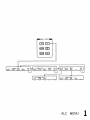
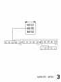
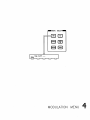
ALC Menu . . .
Frequency Menu .
Marker Menu . .
Modulation Menu
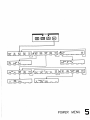
Power Menu . . .
Service Menu . .
Sweep Menu . . .
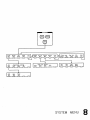
System Menu . .
User Cal Menu . .
.
.
.
.
.
.
.
.
.
.
.
.
.
.
.
.
.
.
.
.
.
.
.
.
.
.
.
.
.
.
.
.
.
.
.
.
.
.
.
.
.
.
.
.
.
.
.
.
.
.
.
.
.
.
2b-3
2b-5
2b-7
2b-9
2b-11
2b-13
2b-15
2b-17
2b-19
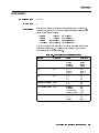
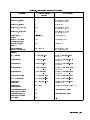
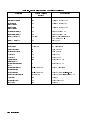
Frequency . . . . . . . . . . . . . .
Range . . . . . . . . . . . . . . .
Resolution . . . . . . . . . . . . .
Frequency Bands (for CW signals) . .
Frequency Modes: . . . . . . . . .
CW and Manual Sweep . . . . . . .
Synthesized Step Sweep . . . . . . .
Synthesized List Mode . . . . . . .
Ramp Sweep Mode . . . . . . . . .
Internal 10 MHz Time Base . . . . .
RF Output . . . . . . . . . . . . .
Output Power . . . . . . . . . . .
Accuracy (dB)4 . . . . . . . . .
Flatness (dB) . . . . . . . . . .
Analog Power Sweep . . . . . . . .
External Leveling . . . . . . . . . .
Source Match . . . . . . . . . . .
Spectral Purity . . . . . . . . . . . .
Spurious Signals . . . . . . . . . .
Single-Sideband Phase Noise (dBc/Hz)
Oset from Carrier . . . . . . . .
.
.
.
.
.
.
.
.
.
.
.
.
.
.
.
.
.
.
.
.
.
.
.
.
.
.
.
.
.
.
.
.
.
.
.
.
.
.
.
.
.
.
.
.
.
.
.
.
.
.
.
.
.
.
.
.
.
.
.
.
.
.
.
.
.
.
.
.
.
.
.
.
.
.
.
.
.
.
.
.
.
.
.
.
.
.
.
.
.
.
.
.
.
.
.
.
.
.
.
.
.
.
.
.
.
2c-2
2c-2
2c-2
2c-2
2c-2
2c-2
2c-3
2c-3
2c-3
2c-3
2c-4
2c-4
2c-5
2c-5
2c-6
2c-6
2c-6
2c-7
2c-7
2c-9
2c-9
2c. Specications
.
.
.
.
.
.
.
.
.
.
.
.
.
.
.
.
.
.
.
.
.
.
.
.
.
.
.
.
.
.
.
.
.
.
.
.
.
.
.
.
.
.
.
.
.
.
.
.
.
.
.
.
.
.
.
.
.
.
.
.
.
.
.
.
.
.
.
.
.
.
.
.
.
.
.
.
.
.
.
.
.
2a-1
2a-1
2a-5
2a-5
2a-6
2a-6
2a-6
2a-6
2a-7
Contents-11
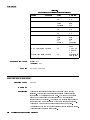
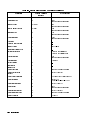
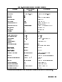
Residual FM (RMS, 50 Hz to 15 kHz bandwidth) .
Modulation . . . . . . . . . . . . . . . . . .
Pulse . . . . . . . . . . . . . . . . . . . .
AM and Scan . . . . . . . . . . . . . . . .
FM . . . . . . . . . . . . . . . . . . . . .
Simultaneous Modulations . . . . . . . . . . .
Internal Modulation Generator Option 002 . . . .
AM, FM . . . . . . . . . . . . . . . . . .
Pulse . . . . . . . . . . . . . . . . . . . .
Modulation Meter . . . . . . . . . . . . . .
General . . . . . . . . . . . . . . . . . . . .
Environmental . . . . . . . . . . . . . . . .
Warm-Up Time . . . . . . . . . . . . . . .
Power Requirements . . . . . . . . . . . . .
Weight & Dimensions . . . . . . . . . . . . .
Adapters Supplied . . . . . . . . . . . . . .
Inputs & Outputs . . . . . . . . . . . . . .
Auxiliary Output . . . . . . . . . . . . . .
RF Output . . . . . . . . . . . . . . . .
External ALC Input . . . . . . . . . . . .
Pulse Input/Output . . . . . . . . . . . .
AM Input . . . . . . . . . . . . . . . . .
FM Input . . . . . . . . . . . . . . . . .
Trigger Input . . . . . . . . . . . . . . .
Trigger Output . . . . . . . . . . . . . . .
10 MHz Reference Input . . . . . . . . . . .
10 MHz Reference Output . . . . . . . . . .
Sweep Output . . . . . . . . . . . . . . .
Stop Sweep Input/Output . . . . . . . . . .
Z-Axis Blanking/Markers Output . . . . . . .
Volts/GHz Output . . . . . . . . . . . . .
Source Module Interface . . . . . . . . . . .
Auxiliary Interface . . . . . . . . . . . . .
Pulse Video Output (Option 002 only) . . . .
Pulse Sync Out (Option 002 only) . . . . . .
AM/FM Output (Option 002 only) . . . . . .
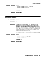
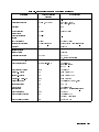
Models . . . . . . . . . . . . . . . . . . .
Options . . . . . . . . . . . . . . . . . . .
Option 001 Add Step Attenuator . . . . . . .
Option 002 Add Internal Modulation Generator
Option 004 Rear Panel RF Output . . . . . .
Option 006 Fast Pulse Modulation . . . . . .
Option 008 1 Hz Frequency Resolution . . . .
Option 700 MATE System Compatibility . . .
Option 806 Rack Slide Kit . . . . . . . . . .
Option 908 Rack Flange Kit . . . . . . . . .
Option 910 Extra Operating & Service Guides .
Option 013 Rack Flange Kit . . . . . . . . .
Option W30 Two Years Additional Return{To{HP
Service . . . . . . . . . . . . . . . . .
Contents-12
2c-9
2c-10
2c-10
2c-11
2c-12
2c-12
2c-13
2c-13
2c-13
2c-13
2c-14
2c-14
2c-14
2c-14
2c-14
2c-14
2c-15
2c-15
2c-15
2c-15
2c-15
2c-15
2c-15
2c-15
2c-15
2c-16
2c-16
2c-16
2c-16
2c-16
2c-16
2c-16
2c-16
2c-16
2c-17
2c-17
2c-17
2c-17
2c-17
2c-17
2c-17
2c-17
2c-17
2c-17
2c-18
2c-18
2c-18
2c-18
2c-18
3. Installation
Initial Inspection . . . . . . . . . . . . . . . .
Equipment Supplied . . . . . . . . . . . . . .
Options Available . . . . . . . . . . . . . . .
Preparation for Use . . . . . . . . . . . . . . .
Power Requirements . . . . . . . . . . . . .
Line Voltage and Fuse Selection . . . . . . . .
Power Cable . . . . . . . . . . . . . . . . .
Language Selection . . . . . . . . . . . . . .
How to View or Change a Language Selection from
the Front Panel . . . . . . . . . . . . .
How to Select a Language on an Instrument
without a Front Panel . . . . . . . . . .
GPIB Address Selection . . . . . . . . . . . .
How to View or Change an GPIB address from the
Front Panel . . . . . . . . . . . . . . .
How to Prevent a Front Panel Change to an GPIB
Address . . . . . . . . . . . . . . . .
How to Set the GPIB Address on a Swept Signal
Generator without a Front Panel . . . . .
Mating Connectors . . . . . . . . . . . . . .
10 MHz Frequency Reference Selection and Warmup
Time . . . . . . . . . . . . . . . . . .
Operating Environment . . . . . . . . . . . .
Chassis Kits . . . . . . . . . . . . . . . . . .
Rack Mount Slide Kit (Option 806) . . . . . . .
Installation Procedure . . . . . . . . . . . .
Rack Flange Kit for Swept Signal Generators with
Handles Removed (Option 908) . . . . . . .
Installation Procedure . . . . . . . . . . . .
Rack Flange Kit for Swept Signal Generators with
Handles Attached (Option 913) . . . . . . .
Installation Procedure . . . . . . . . . . . .
Storage and Shipment . . . . . . . . . . . . . .
Environment . . . . . . . . . . . . . . . . .
Package the Swept Signal Generator for Shipment
Converting HP/Agilent 8340/41 Systems to Agilent
8360 B-Series Systems . . . . . . . . . . . .
Manual Operation . . . . . . . . . . . . . .
Compatibility . . . . . . . . . . . . . . .
Front Panel Operation . . . . . . . . . . .
Instrument Preset Conditions . . . . . . .
System Connections . . . . . . . . . . . . .
The HP/Agilent 8510 Network Analyzer . . . .
The HP/Agilent 8757C/E Scalar Network Analyzer
The HP/Agilent 83550 Series Millimeter-wave
Source Modules . . . . . . . . . . . . .
The HP/Agilent 8970B Noise Figure Meter . .
Remote Operation . . . . . . . . . . . . . .
Language Compatibility . . . . . . . . . . .
Network Analyzer Language . . . . . . . . .
3-1
3-2
3-2
3-3
3-3
3-3
3-4
3-6
3-6
3-6
3-7
3-8
3-8
3-8
3-8
3-8
3-9
3-10
3-10
3-11
3-13
3-14
3-15
3-16
3-17
3-17
3-18
3-19
3-20
3-20
3-20
3-20
3-21
3-21
3-22
3-22
3-22
3-23
3-23
3-23
Contents-13
Test and Measurement System Language . .
Control Interface Intermediate Language . .
Converting from Network Analyzer Language to
SCPI . . . . . . . . . . . . . . . . .
Numeric Suxes . . . . . . . . . . . . .
Status Bytes . . . . . . . . . . . . . . .
4. Operator's Check and Routine Maintenance
Operator's Checks . . . . . . .
Service Information . . . . . .
Local Operator's Check . . . . .
Description . . . . . . . . .
Preliminary Check . . . . . .
Main Check . . . . . . . . .
Routine Maintenance . . . . . .
How to Replace the Line Fuse .
How to Clean the Fan Filter . .
How to Clean the Cabinet . . .
How to Clean the Display Filter
5. Instrument History
Index
Contents-14
.
.
.
.
.
.
.
.
.
.
.
.
.
.
.
.
.
.
.
.
.
.
.
.
.
.
.
.
.
.
.
.
.
.
.
.
.
.
.
.
.
.
.
.
.
.
.
.
.
.
.
.
.
.
.
.
.
.
.
.
.
.
.
.
.
.
.
.
.
.
.
.
.
.
.
.
.
.
.
.
.
.
3-23
3-23
3-23
3-24
3-24
.
.
.
.
.
.
.
.
.
.
.
4-1
4-1
4-2
4-2
4-2
4-3
4-4
4-4
4-5
4-6
4-6
Figures
0-1. Typical Serial Number Label . . . . . . . . . .
1-1. The Agilent 83620B Swept Signal Generator . . .
1-2. Display . . . . . . . . . . . . . . . . . . .
1-3. Entry Area . . . . . . . . . . . . . . . . .
1-4. CW Operation and Start/Stop Frequency Sweep .
1-5. Center Frequency and Span Operation . . . . .
1-6. Power Level and Sweep Time Operation . . . . .
1-7. Continuous, Single, and Manual Sweep Operation
1-8. Marker Operation . . . . . . . . . . . . . .
1-9. Saving and Recalling an Instrument State . . . .
1-10. Power Sweep and Power Slope Operation . . . .
1-11. ALC Circuit Externally Leveled . . . . . . . .
1-12. Typical Diode Detector Response at 25C . . . .
1-13. Leveling with a Power Meter . . . . . . . . . .
1-14. MM-wave Source Module Leveling . . . . . . .
1-15. MM-wave Source Module Leveling Using a Microwave
Amplier . . . . . . . . . . . . . . . . .
1-16. Reverse Power Eects, Coupled Operation with 08
dBm Output . . . . . . . . . . . . . . .
1-17. Reverse Power Eects, Uncoupled Operation with 08
dBm Output . . . . . . . . . . . . . . .
1-18. Creating a User Flatness Array Automatically . .
1-19. Creating a User Flatness Array . . . . . . . . .
1-20. Creating Arbitrarily Spaced Frequency-Correction
Pairs in a Swept mm-wave Environment . . .
1-21. Scalar System Conguration . . . . . . . . . .
1-22. Automatically Characterizing and Compensating for
a Detector . . . . . . . . . . . . . . . .
1-23. Decision Tree for ALC Bandwidth Selection . . .
1-24. SCPI Command Types . . . . . . . . . . . .
1-25. A Simplied Command Tree . . . . . . . . . .
1-26. Proper Use of the Colon and Semicolon . . . . .
1-27. Simplied SWEep Command Tree . . . . . . .
1-28. Voltage Controlled Oscillator Test . . . . . . .
1-29. Simplied Program Message Syntax . . . . . . .
1-30. Simplied Subsystem Command Syntax . . . . .
1-31. Simplied Common Command Syntax . . . . .
1-32. Simplied Response Message Syntax . . . . . .
1-33. Generalized Status Register Model . . . . . . .
1-34. Typical Status Register Bit Changes . . . . . .
1-35. Generalized Trigger Model . . . . . . . . . . .
1-36. Inside the Idle State . . . . . . . . . . . . .
vii
1-3
1-4
1-5
1-7
1-9
1-11
1-13
1-15
1-17
1-19
1-23
1-25
1-27
1-28
1-29
1-31
1-31
1-34
1-37
1-40
1-43
1-47
1-50
1-67
1-68
1-70
1-71
1-77
1-80
1-81
1-82
1-82
1-106
1-108
1-110
1-111
Contents-15
1-37. Inside the Initiate State . . . . . . . . . . . .
1-38. Inside an Event Detection State . . . . . . . .
1-39. Inside the Sequence Operation State . . . . . .
1-40. The INIT Trigger Conguration . . . . . . . .
1-41. The TRIG Trigger Conguration . . . . . . . .
1-42. 8360 Simplied Trigger Model . . . . . . . . .
A-1. ALC System Simplied Block Diagram . . . . .
A-2. Typical External Leveling Hookup . . . . . . .
C-1. Auxiliary Interface Connector . . . . . . . . .
C-2. GPIB Connector and Cable . . . . . . . . . .
C-3. Interface Signals of the Source Module Connector .
F-1. Basic User Flatness Conguration Using an
HP/Agilent 437B Power Meter . . . . . . .
F-2. User Flatness Correction Table as Displayed by the
Swept Signal Generator . . . . . . . . . .
F-3. The Sources of ALC Calibration Correction Data .
F-4. Array Conguration when the Correction Data
Frequency Span is a Subset of the Swept Signal
Generator Frequency Span . . . . . . . . .
M-1. ALC Block Diagram . . . . . . . . . . . . .
M-2. Power Accuracy Over the AM Dynamic Range . .
M-3. FM Deviation and Rate Limits . . . . . . . . .
M-4. ALC Block Diagram . . . . . . . . . . . . .
M-5. Pulse Modulation System . . . . . . . . . . .
M-6. Video Feedthrough . . . . . . . . . . . . . .
P-1. How 4 5 Works . . . . . . . . . . . . . .
S-1. Connections Required for a Two-Tone Scalar
Network Analyzer Measurement System . . .
2b-1. ALC Menu . . . . . . . . . . . . . . . . .
2b-2. Frequency Menu . . . . . . . . . . . . . . .
2b-3. Marker Menu . . . . . . . . . . . . . . . .
2b-4. Modulation Menu . . . . . . . . . . . . . .
2b-5. Power Menu . . . . . . . . . . . . . . . . .
2b-6. Service Menu . . . . . . . . . . . . . . . .
2b-7. Sweep Menu . . . . . . . . . . . . . . . . .
2b-8. System Menu . . . . . . . . . . . . . . . .
2b-9. User Cal Menu . . . . . . . . . . . . . . . .
3-1. AC Power Cables Available . . . . . . . . . .
3-2. Rear Panel GPIB Switch . . . . . . . . . . .
3-3. Removing the Side Straps and Feet . . . . . . .
3-4. Chassis Slide Kit . . . . . . . . . . . . . . .
3-5. Rack Mount Flanges for Swept Signal Generators
with Handles Removed . . . . . . . . . . .
3-6. Rack Mount Flanges for Swept Signal Generators
with Handles Attached . . . . . . . . . . .
4-1. Replacing the Line Fuse . . . . . . . . . . . .
4-2. Removing the Fan Filter . . . . . . . . . . .
PRIOR
Contents-16
1-111
1-113
1-114
1-115
1-116
1-117
A-5
A-8
C-7
C-8
C-10
F-6
F-7
F-8
F-8
M-13
M-16
M-18
M-20
M-20
M-22
P-12
S-65
2b-3
2b-5
2b-7
2b-9
2b-11
2b-13
2b-15
2b-17
2b-19
3-5
3-7
3-11
3-12
3-14
3-16
4-4
4-5
Tables
1-1. Keys Under Discussion in This Section . . . . .
1-2. SWEep Command Table . . . . . . . . . . .
1-3. SCPI Data Types . . . . . . . . . . . . . .
1-4. Sample Swept Signal Generator Commands . . .
C-1. Pin Description of the Auxiliary Interface . . . .
D-1. Mnemonics used to Indicate Status . . . . . . .
S-1. 8360 SCPI COMMAND SUMMARY . . . . . .
3-1. Adapter Descriptions and Part Numbers Shipped
with Each Swept Signal Generator Model . . .
3-2. Language GPIB Addresses . . . . . . . . . . .
3-3. Factory-Set GPIB Addresses . . . . . . . . . .
3-4. Rack Mount Slide Kit Contents . . . . . . . .
3-5. Rack Flange Kit for Swept Signal Generators with
Handles Removed Contents . . . . . . . . .
3-6. Rack Flange Kit for Swept Signal Generators with
Handles Attached Contents . . . . . . . . .
3-7. Instrument Preset Conditions for the HP/Agilent
8360/8340/8341 . . . . . . . . . . . . . .
3-8. Numeric Suxes . . . . . . . . . . . . . . .
3-9. Programming Language Comparison . . . . . .
4-1. Fuse Part Numbers . . . . . . . . . . . . . .
1-21
1-71
1-83
1-88
C-7
D-7
S-18
3-2
3-6
3-7
3-10
3-13
3-15
3-20
3-24
3-25
4-4
Contents-17
1
Getting Started
What Is In This
Chapter
This chapter contains information on how to use the Agilent
8360 B-Series swept signal generator. The information is separated
into three sections.
Basic
For the novice user unfamiliar with the 8360 B-Series
swept signal generator. This section describes the
basic features of the swept signal generator.
Advanced
For the user familiar with swept signal generators,
but not necessarily familiar with how to use the
special features of the 8360 B-Series swept signal
generator.
For the user wishing to program an 8360 B-Series
swept signal generator. This section contains
an introduction to Standard Commands for
Programmable Instruments language (SCPI), Agilent
Technologies' implementation of IEEE-488.2-1987,
and an introduction to the Analyzer programming
language.
If you are unpacking a new swept signal generator, refer to the
installation suggestions provided in Chapter 3, \Installation".
Programming
Note
Getting Started Introduction 1-1
How To Use This
Chapter
Equipment Used In
Examples
To use this chapter eectively, refer to the tabbed section \Menu
Maps". Menu maps can be folded out to be viewed at the same time
as the Getting Started information, as illustrated.
The following table lists the equipment used in the operation
examples shown in this chapter. You can substitute equipment, but
be aware that you may get dierent results than those shown.
Equipment Used In Examples
Equipment
Recommended
HP/Agilent
Model Numbers
Power Meter
436A/437B
Power Sensor
8485A
Power Splitter
11667B
Oscilloscope
1740A
mm-Wave Source Module 83556A
1-2 Getting Started Introduction
Power Amplier
8349B
Coupler
11691D
Detector
8474D
Getting Started Basic
Introducing the
8360 B-Series
The 8360 B-Series swept signal generators are high performance,
broadband frequency swept signal generators.
Swept Signal
Generators
Figure 1-1. The Agilent 83620B Swept Signal Generator
initializes the front panel settings and runs the swept signal
generator through a brief self-test. In the following examples, unless
stated otherwise, begin by pressing 4
5.
4PRESET5
PRESET
Getting Started Basic 1-3
Display Area
Figure 1-2. Display
This area typically displays
the frequency and power information of the current instrument
state. When data entry is expected, the swept signal generator
uses all or part of this area to record the entries. The active entry
arrow (-->) indicates the active entry function and its current
value.
Message Line: This line is used to display:
ALC level status.
Unlock information.
Timebase status.
RF output status.
Softkey Label Area: This area displays the name of the softkey
directly below it.
Softkeys: These keys activate the functions indicated by the labels
directly above them.
Active Entry and Data Display Area:
1-4 Getting Started Basic
Entry Area
All function values are changed via the rotary knob and/or keys of
the entry area.
Figure 1-3. Entry Area
The following are active only when the swept signal generator
expects an input.
4
5: This key lets you turn o or on the active entry
area. Turning o the entry area after a value is entered prevents
accidental changes.
ENTRY ON LED: This LED lights when the entry area is active.
Arrow Keys: The up/down arrow keys let you increase or decrease
a numeric value. The left/right arrow keys choose a signicant
digit indicated by an underline.
Rotary Knob: The rotary knob increases or decreases a numeric
value. The rotary knob can be used in combination with the
left/right arrow keys to change the increment size.
Terminator Keys: After the numeric entry keys are used to enter a
value, these keys dene the units.
Negative Sign/Backspace Key: If a data entry is in progress, this
key backspaces over the last digit entered, otherwise a negative
sign is entered.
Numeric Entry Keys: These keys enter specic numbers in the
active entry area and must be followed by one of the terminator
keys before the function value changes.
ENTRY ON/OFF
Getting Started Basic 1-5
CW Operation and
Start/Stop
Frequency Sweep
CW Operation
CW operation is one of the major functions of the swept signal
generator, and is easy to do using front panel keys. In CW operation,
the swept signal generator produces a single, low-noise, synthesized
frequency. Try this example: Press 4 5 4 5 4 5 4 5 4 5 4 5 4 5 4 5 4 5 4 5
4
5.
Check the active entry area. It indicates:
CW
1
2
.
3
4
5
6
7
8
GHz
--> CW: 12345.678000 MHz
The data display area indicates CW operation and the frequency
that you entered. The ENTRY ON LED is lit and the green SWEEP
LED is o.
Try other frequencies. Experiment with the rotary knob and the
arrow keys as alternate methods of data entry.
Start/Stop Frequency
Sweep
The swept signal generator can sweep a frequency span as wide as
the frequency range of the instrument, or as narrow as 0 Hz (swept
CW).
In start/stop sweep operation, the swept signal generator produces
a sweep from the selected start frequency to the selected stop
frequency.
For example:
Press 4 5 4 5 4 5 4 5 4 5 4 5.
Press 4 5 4 5 4 5 4 5 4 5 4 5.
The data display area indicates the start frequency and the stop
frequency. The green SWEEP LED is on (periodically o when
sweep is retracing). Because this is the active function, the active
entry area indicates:
START
STOP
4
7
.
.
5
8
6
9
GHz
GHz
--> STOP FREQUENCY: 7890.000000 MHz
Any subsequent entries change the stop frequency. To change the
start frequency, press 4 5, which remains the active function until
you press a dierent function key.
START
1-6 Getting Started Basic
Figure 1-4. CW Operation and Start/Stop Frequency Sweep
CW Operation
Start/Stop
Frequency Sweep
1. Press 4CW5.
2. Enter value.
3. Press terminator key.
1.
2.
3.
4.
5.
6.
Press 4START5.
Enter value.
Press terminator key.
Press 4STOP5.
Enter value.
Press terminator key.
Getting Started Basic 1-7
Center
Frequency/Span
Operation
Center frequency/span is another way of establishing swept
operation. This is just a dierent way of dening sweep limits. As an
example of center frequency/span operation:
Press 4
5 45 4
5.
Press 4 5 4 5 4 5.
The swept signal generator is now sweeping from 3.5 to 4.5 GHz (to
view these gures, press either 4 5 or 4 5, then 4 5). The
data display area indicates the center frequency as well as the span.
Notice that the green SWEEP LED is on.
While span is the active function, try the rotary knob and arrow
keys. This symmetrical increase or decrease of the frequency span
about the center frequency is one reason that center frequency/span
swept operation is used instead of start/stop frequency sweep.
Another example illustrates the subtleties of center frequency/span.
Press 4
5 45 4
5.
Press 4 5 4 5 4 5.
Notice that the center frequency changed. This is because the center
frequency could not accommodate a span of 8 GHz without exceeding
the lower frequency limit of the swept signal generator's specied
frequency range. If the low or high frequency range limits are
exceeded, the inactive (center or span) function is reset. Experiment
with the rotary knob and the arrow keys as alternate methods of
data entry.
CENTER
SPAN
1
4
GHz
GHz
START
CENTER
SPAN
1-8 Getting Started Basic
8
4
GHz
GHz
STOP
SPAN
Figure 1-5. Center Frequency and Span Operation
Center Frequency
Operation
Span Operation
1. Press 4CENTER5.
2. Enter value.
3. Press terminator key.
1. Press 4SPAN5.
2. Enter value.
3. Press terminator key.
Getting Started Basic 1-9
Power Level and
Sweep Time
Operation
Power Level Operation
The swept signal generator can produce leveled power for CW,
swept frequency, or power sweep operation. The selected power level
can range from -20 dBm (-110 dBm for option 001 swept signal
generators) to +25 dBm.
For practice: Press 4
5 405 4 5 4 5 4
5. The active entry
area shows:
POWER LEVEL
--> POWER LEVEL:
020.00
2
0
dB(m)
dBm
If the selected power level is beyond the range of the swept signal
generator, the closest possible power is shown in both the data
display area and the active entry area. If the selected power level
exceeds the maximum leveled power the swept signal generator is
able to produce, the unleveled message UNLVLED appears on the
message line. Experiment with the rotary knob and the arrow keys
as alternate methods of data entry.
Sweep Time Operation
In typical applications the sweep time can vary tremendously, from
milliseconds in a network analyzer system, to more than a minute in
thermistor-based power meter systems.
Press 4 5 4 5 4 5.
Press 4 5 4 5 4 5.
Press 4
5 4 5 4 5 4 5 4 5.
Watch the green SWEEP LED, it blinks every 2.5 seconds. The LED
blinks at each retrace.
For the fastest sweep speed for which all specications are
guaranteed, the swept signal generator must be in automatic sweep
time selection.
Refer to menu map 7.
Press SWEEP 4 5.
Select more 1/3 .
Select SwpTime Auto .
Notice that the active entry area indicates:
START
STOP
4
6
GHz
GHz
SWEEP TIME
2
.
5
sec
MENU
NNNNNNNNNNNNNNNNNNNNNNNNNN
NNNNNNNNNNNNNNNNNNNNNNNNNNNNNNNNNNNNNN
--> SWEEP TIME: 100.0 mSec
AUTO
When the swept signal generator is in automatic sweep time
selection, the active entry area displays AUTO along with the current
sweep time. Faster sweep speeds than this are possible, turn the
rotary knob counter-clockwise until the display no longer changes.
Notice that AUTO is no longer displayed.
1-10 Getting Started Basic
Figure 1-6. Power Level and Sweep Time Operation
Power Level
Operation
Sweep Time
Operation
1. Press 4POWER LEVEL5.
2. Enter value.
3. Press 4dB(m)5.
1. Press 4SWEEP TIME5.
2. Enter value.
3. Press terminator key.
Getting Started Basic 1-11
Continuous, Single,
and Manual Sweep
Operation
Continuous sweep is the operation mode set when the swept
signal generator is preset. It simply means that when the swept
signal generator is performing a swept operation, the sweeps will
continuously sweep-retrace-sweep-retrace until a dierent sweep mode
is selected. To choose this sweep mode, press 4 5.
To change from continuous sweep to single sweep operation, press
4
5. This causes the swept signal generator to abort the sweep in
progress and switch to the single sweep mode. This initial keystroke
causes the swept signal generator to switch sweep modes, but it
does not initiate a single sweep. A second keystroke (press 4 5)
initiates a single sweep. When the swept signal generator is in single
sweep operation, the amber LED above the key lights. When the
swept signal generator is actually performing a sweep in single sweep
mode, the green SWEEP LED lights.
The manual sweep mode lets you use the rotary knob to either sweep
from the start frequency to the stop frequency or to sweep power.
Refer to menu map 7, SWEEP.
Press 4
5.
Press SWEEP 4 5.
Select Manual Sweep .
The active entry area displays:
CONT
SINGLE
SINGLE
PRESET
MENU
NNNNNNNNNNNNNNNNNNNNNNNNNNNNNNNNNNNNNN
--> SWEPT MANUAL:
XXXXXXXXX MHz
Use the rotary knob to sweep from the start to the stop frequency.
The green SWEEP LED is o in manual sweep mode because the
sweeps are synthesized.
1-12 Getting Started Basic
Figure 1-7. Continuous, Single, and Manual Sweep Operation
Single Sweep
Continuous Sweep
Manual Sweep
1. Press 4SINGLE5.
1. Press 4CONT5.
1. Press SWEEP 4MENU5.
2. Press Manual Sweep .
3. Use the rotary knob to adjust frequency.
NNNNNNNNNNNNNNNNNNNNNNNNNNNNNNNNNNN
Getting Started Basic 1-13
Marker Operation
The swept signal generator has ve frequency markers that can
be used as xed frequency \landmarks," or as variable frequency
pointers on a CRT display. To view the marker features of the swept
signal generator on a CRT, connect the swept signal generator as
shown in Figure 1-8.
Refer to menu map 3, MARKER.
Press 4
5.
Press 4 5 4 5 4 5.
Press 4 5 4 5 4 5.
Press 4
5.
Select Marker M1 and enter 4 5 4 5.
The swept signal generator is sweeping from 3 to 7 GHz, with a
100 ms sweep speed. A frequency marker is set at 4 GHz, which
causes an intensied dot to appear on the CRT. To obtain an
amplitude spike at that frequency, select Ampl Markers . Notice
that you can set the amplitude of the spike with the rotary knob or
entry keys. To return to the intensied dot representation, select
Ampl Markers (asterisk o).
PRESET
START
STOP
3
7
GHz
GHz
MARKER
NNNNNNNNNNNNNNNNNNNNNNNNNNNNN
4
GHz
NNNNNNNNNNNNNNNNNNNNNNNNNNNNNNNNNNNNNN
NNNNNNNNNNNNNNNNNNNNNNNNNNNNNNNNNNNNNN
Caution
Amplitude markers increase the output power at the marker
frequency. Provide protection to devices that could be damaged.
For a second marker, select Marker M2 and enter 4 5 4 5 4 5 4 5.
This process can be continued for all ve markers. Note that the
marker displayed in the active entry area is \active" and can be
controlled by the rotary knob, arrow keys, and numeric entry keys.
Once the M1 and M2 markers are established, the marker sweep
function, softkey M1--M2 Sweep , temporarily changes the original
start/stop frequencies to those of markers M1 and M2. Select
M1--M2 Sweep . Notice that the swept signal generator now is
sweeping from 4 to 5.5 GHz. Use this function to focus in on a
selected portion of the frequency sweep. Select M1--M2 Sweep again.
This turns the function o and returns the swept signal generator to
its original sweep parameters. To change the start/stop frequencies
for the swept signal generator, not just temporarily, use the softkey
Start=M1 Stop=M2 .
As an example of the delta marker function:
Select Marker M3 and enter 4 5 4 5 4 5 4 5.
Select Delta Marker .
The frequency dierence between marker 3 and marker 1 is displayed,
and the CRT trace is intensied between the two markers. The active
entry area displays:
NNNNNNNNNNNNNNNNNNNNNNNNNNNNN
5
.
5
GHz
NNNNNNNNNNNNNNNNNNNNNNNNNNNNNNNNNNNNNN
NNNNNNNNNNNNNNNNNNNNNNNNNNNNNNNNNNNNNN
NNNNNNNNNNNNNNNNNNNNNNNNNNNNNNNNNNNNNN
NNNNNNNNNNNNNNNNNNNNNNNNNNNNNNNNNNNNNNNNNNNNNNNNNN
NNNNNNNNNNNNNNNNNNNNNNNNNNNNN
6
.
7
GHz
NNNNNNNNNNNNNNNNNNNNNNNNNNNNNNNNNNNNNNNNN
--> DELTA MKR (3-1) : 2700.000000 MHz
1-14 Getting Started Basic
Marker 1 was chosen because it is selected as the delta marker
reference. To change reference markers, select Delta Mkr Ref .
Select M2 as the reference. Watch the display change to indicate:
NNNNNNNNNNNNNNNNNNNNNNNNNNNNNNNNNNNNNNNNN
NNNNNNNN
--> DELTA MKR (3-2) : 1200.000000 MHz
You can choose any of the ve markers as a reference, but when delta
marker is on, if the reference marker has a frequency value higher
than the last active marker, the dierence between the frequencies is
negative and is displayed as such by the swept signal generator. The
CRT display continues to intensify the dierence between the two
markers.
When delta marker is showing in the active entry area, the ENTRY
area is active. Rotate the rotary knob and watch the frequency
dierence change. The last active marker (in this case, marker 3)
changes frequency value, not the reference marker.
Figure 1-8. Marker Operation
Marker Operation
1.
2.
3.
4.
Delta Marker
Operation
Press 4MARKER5.
Select a marker key ( M1 . . . M5 ).
Enter value.
Press terminator key.
NNNNNNN
NNNNNNN
1. Press 4MARKER5.
2. Select a marker key ( M1 . . . M5 ).
3. Enter value.
4. Press terminator key.
5. Select a dierent marker key ( M1 . . . M5 ).
6. Enter value.
7. Press terminator key.
8. Select Delta Mkr Ref .
9. Select one of the previously chosen markers.
10. Press 4PRIOR5.
11. Select Delta Marker .
NNNNNNN
NNNNNNN
NNNNNNN
NNNNNNN
NNNNNNNNNNNNNNNNNNNNNNNNNNNNNNNNNNNNN
NNNNNNNNNNNNNNNNNNNNNNNNNNNNNNNNNNN
Getting Started Basic 1-15
Saving and
Recalling an
Instrument State
The save/recall registers store and access a previously set instrument
state.
For example, set the swept signal generator to sweep from 3 GHz to
15 GHz at a 010 dB power level, with markers 1 and 2 set at 4.5 and
11.2 GHz.
Press 4 5 4 5 4 5.
Press 4 5 4 5 4 5 4 5.
Press 4
5 405 4 5 4 5 4
5.
Press 4
5.
Select Marker M1 4 5 4 5 4 5 4 5.
Select Marker M2 4 5 4 5 4 5 4 5 4 5.
To save this instrument state in register 1, press 4 5 4 5. To verify
that the swept signal generator has saved this state:
Press 4
5.
Press 4
5 4 5.
Press 4
5.
The active entry area displays:
START
STOP
3
1
GHz
5
GHz
POWER LEVEL
1
0
dB(m)
MARKER
NNNNNNNNNNNNNNNNNNNNNNNNNNNNN
4
.
5
GHz
1
1
.
2
NNNNNNNNNNNNNNNNNNNNNNNNNNNNN
GHz
SAVE
1
PRESET
RECALL
1
MARKER
--> RECALL REGISTER: 1 RECALLED
Notice the sweep end points, power level, and the asterisks next to
the marker 1 and 2 key labels.
You can save instrument states in registers 1 through 8. Register
0 saves the last instrument state before power is turned o. When
power is turned on, register 0 is automatically recalled.
1-16 Getting Started Basic
Figure 1-9. Saving and Recalling an Instrument State
Save
Recall
1. Set up swept signal generator as desired.
2. Press 4SAVE5.
3. Press a number 1 through 8.
1. Press 4RECALL5.
2. Press a number 0 through 8.
Getting Started Basic 1-17
Power Sweep and
Power Slope
Operation
Power Sweep Operation
The power sweep function allows the power output to be swept
(positive or negative) when the swept signal generator is in the
CW frequency mode. The power output of the swept signal
generator determines the maximum leveled power sweep that can be
accomplished. For this example, refer to the \Menu Map" section.
Zero and calibrate the power meter.
Connect the instruments as shown in Figure 1-10.
Press 4 5 4 5 4 5.
Press 4
5 45 4
5.
Press 4
5 45 4 5 4
5.
Set the power meter to dB[REF] mode.
The swept signal generator is ready to produce a 4 GHz CW signal
at 0 dBm power out, with a 2 second sweep rate whenever a single
sweep is executed. The power meter is ready to measure the power
level relative to a starting point of 0 dBm.
Press POWER 4 5.
Select Power Sweep and enter 4 5 4 5 (asterisk on).
Press 4 5.
Watch the relative power indication on the power meter. At the end
of the sweep the power meter indicates +7 dB. The active entry area
on the swept signal generator indicates:
CW
4
GHz
POWER LEVEL
SWEEP TIME
0
dBm
2
sec
SINGLE
MENU
NNNNNNNNNNNNNNNNNNNNNNNNNNNNNNNNNNN
7
dB(m)
SINGLE
--> POWER SWEEP:
7.00 dB/SWP
Now enter 4 5 4 5 4 5 (power sweep is still the active entry
function).
Press 4 5.
This time the power meter indicates less than the power sweep
requested. Note that the swept signal generator is unleveled, UNLVD.
This happens because the swept signal generator's output power
at the start of the sweep is 0 dB and the requested power sweep
takes the swept signal generator beyond the range where it is able to
produce leveled power. The range of the power sweep is dependent
on the ALC range and can be oset if a step attenuator (Option 001)
is present.
Select Power Sweep to turn this function o (no asterisk).
Press 4
5 405 4 5 4 5.
On the power meter, press dB[REF] to reset the reference level.
2
5
dB(m)
SINGLE
NNNNNNNNNNNNNNNNNNNNNNNNNNNNNNNNNNN
POWER LEVEL
1-18 Getting Started Basic
2
0
Select Power Sweep (asterisk on).
Press 4 5.
The swept signal generator performs a power sweep beginning at
020 dBm and ending at +5 dBm. The power meter indicates
+25 dB.
NNNNNNNNNNNNNNNNNNNNNNNNNNNNNNNNNNN
SINGLE
Power Slope Operation
This function allows for compensation of high frequency system or
cable losses by linearly increasing the power output as the frequency
increases. For this example, refer to the \Menu Map" section.
Press Power Slope , the active entry area displays:
--> RF SLOPE: X.XX dB/GHz, where X is a numeric value.
Power slope is now active, notice that an asterisk is next to the key
label.
Use the entry keys, rotary knob, or arrow keys to enter a value for
the linear slope.
Press Power Slope again to turn this feature o.
NNNNNNNNNNNNNNNNNNNNNNNNNNNNNNNNNNN
NNNNNNNNNNNNNNNNNNNNNNNNNNNNNNNNNNN
Figure 1-10. Power Sweep and Power Slope Operation
Power Sweep
Power Slope
1.
2.
3.
4.
1.
2.
3.
4.
Press POWER 4MENU5.
Select Power Sweep .
Enter a value.
Press terminator key.
NNNNNNNNNNNNNNNNNNNNNNNNNNNNNNNN
Press POWER 4MENU5.
Select Power Slope .
Enter a value.
Press terminator key.
NNNNNNNNNNNNNNNNNNNNNNNNNNNNNNNN
Getting Started Basic 1-19
Advanced
Getting Started
Advanced
This section of Chapter 1 describes the use of many of the unique
features of the 8360 B-Series swept signal generators. The format
used is similar to the one used on the previous pages. When referred
to a menu map number, go to the Menu Map tab and unfold the
menu map so that you can view it together with the text.
Some menus have more than one page of softkeys. Select the
more m/n softkey to view the next page of softkeys. more m/n is
not included in the keystrokes given in these procedures.
NNNNNNNNNNNNNNNNNNNNNNNNNN
NNNNNNNNNNNNNNNNNNNNNNNNNN
Table 1-1. Keys Under Discussion in This Section
Paragraph Heading
Externally Leveling the Swept Signal Generator
Keys
Leveling Point ExtDet
Coupling Factor
POWER LEVEL
Set Atten
Leveling Point PwrMtr
Pwr Mtr Range
Leveling Point Module
Mdl Lev Menu
Working with Mixers/Reverse Power Eects
Uncoupl Atten
Leveling Mode Normal
Working with Spectrum Analyzers/
Leveling Mode ALCoff
Reverse Power Eects
Leveling Mode Search
\Optimizing Swept Signal Generator Performance" Fltness Menu
Delete Menu
Auto Fill Start
Auto Fill Stop
Auto Fill Incr
Mtr Meas Menu
FLTNESS ON/OFF
Enter Freq
Enter Corr
Freq Follow
List Menu
Copy List
Sweep Mode List
Ext Det Cal
Getting Started Advanced 1-21
Advanced
Table 1-1.
Keys Under Discussion in This Section (continued)
Paragraph Heading
Keys
\Optimizing Swept Signal Generator Performance" Auto Track
continued
Peak RF Always
Peak RF Once
Swp Span Cal Once
Swp Span Cal Always
AM BW Cal Always
AM BW Cal Once
FullUsr Cal
AM On/Off 100%/V
AM On/Off 10dB/V
Deep AM
Using Step Sweep
Creating and Using a Frequency List
Using the Security Features
Changing the Preset Parameters
USER DEFINED MENU
ASSIGN
Step Swp Menu
List Menu
Delete Menu
Enter List Freq
Enter List Offset
Enter List Dwell
Pt Trig Menu
Zero Freq
Save Lock
Clear Memory
Blank Display
Save Usr Preset
Preset Mode User
PRESET
For more information, each of these keys has a separate entry in
Chapter 2.
1-22 Getting Started Advanced
Externally Leveling
the Swept Signal
Generator
Leveling with
Detectors/Couplers
/Splitters
In externally leveled operations, the output power from the swept
signal generator is detected by an external sensor. The output of this
detector is returned to the leveling circuitry, and the output power
is automatically adjusted to keep power constant at the point of
detection.
Figure 1-11 illustrates a typical setup for external leveling. When
externally leveled, the power level feedback is taken from the external
negative detector input rather than the internal detector. This
feedback voltage controls the ALC system to set the desired RF
output. Refer to Figure A-1 in Chapter 2 for a block diagram of the
swept signal generator's ALC circuitry.
Figure 1-11. ALC Circuit Externally Leveled
Getting Started Advanced 1-23
To level externally:
1. Set up the equipment as shown. For this example, the
detector/coupler setup is used.
2. Refer to menu map 1.
3. Press 4 5.
4. Select Leveling Point ExtDet .
5. Set the coupling factor. Select Coupling Factor 405 4 5 4 5
4
5.
Power splitters have a coupling factor of 0 dB.
ALC
NNNNNNNNNNNNNNNNNNNNNNNNNNNNNNNNNNNNNNNNNNNNNNNNNNNNNNNNNNNNNNNNN
NNNNNNNNNNNNNNNNNNNNNNNNNNNNNNNNNNNNNNNNNNNNNNN
2
0
dB(m)
Note
Hint
1-24 Getting Started Advanced
Figure 1-12 shows the input power versus output voltage
characteristics for typical HP/Agilent diode detectors. From the
chart, the leveled power at the diode detector input resulting from
any external level voltage setting may be determined. The range of
power adjustment is approximately 030 dBm to +18 dBm.
Automatically characterize and compensate for the detector
used by performing a detector calibration. Refer to \Using
Detector Calibration" in the \Optimizing Swept Signal Generator
Performance" section.
Figure 1-12. Typical Diode Detector Response at 25 C
Getting Started Advanced 1-25
External Leveling Used With the Optional Step Attenuator
Some external leveling applications require low output power from
the swept signal generator. The swept signal generator automatically
uncouples the attenuator from the ALC system for all external
leveling points.
Press 4
5. Note the display. It shows:
POWER LEVEL
--> ATTEN 0 dB, POWER LEVEL:
0.00 dBm
For example, leveling the output of a 30 dB gain amplier to a
level of 010 dBm requires the output of the swept signal generator
to be around 040 dBm when leveled. At some frequencies this
level is beyond the range of the ALC modulator alone. If so, the
LOW UNLVLED warning message is displayed. Inserting 40 dB of
attenuation results in an ALC level of 0 dBm, which is well within
the range of the ALC. At 20 GHz, 30 dB attenuation is a better
choice as it results in an ALC level of 010 dBm. This gives a margin
for AM or other functions that vary the power level.
For optimum display accuracy and minimum noise, the ALC
level should be greater than 010 dBm. This is achieved by using
attenuation equal to the tens digit of output power. Example:
desired output power = 043 dBm; use:
--> ATTEN:
40 dB, ALC
1. Press POWER 4
2. Select Set Atten
.
MENU5
NNNNNNNNNNNNNNNNNNNNNNNNNNNNN
Hint
1-26 Getting Started Advanced
03
dBm
.
445 405 4dB(m)5
To obtain atness corrected power, refer to \Creating and Applying
the User Flatness Correction Array" in the \Optimizing Swept Signal
Generator Performance" section.
Leveling with Power
Meters
Leveling with a power meter is similar to leveling with a diode
detector. Figure 1-13 shows the setup for power meter leveling.
Figure 1-13. Leveling with a Power Meter
1.
2.
3.
4.
5.
Set up the equipment as shown. Be sure to set the power meter to
manual range mode and note the range.
Refer to menu map 1.
Press 4 5.
Select Leveling Point PwrMtr .
Select Pwr Mtr Range . Enter the range value set for the power
meter as noted in step 1.
6. Select Coupling Factor , press 4 5 4 5.
Unlike detector leveling, power meter leveling provides calibrated
power out of the leveled RF port.
To obtain atness corrected power, refer to \Creating and Applying
the User Flatness Correction Array" in the \Optimizing Swept Signal
Generator Performance" section.
ALC
NNNNNNNNNNNNNNNNNNNNNNNNNNNNNNNNNNNNNNNNNNNNNNNNNNNNNNNNNNNNNNNNN
NNNNNNNNNNNNNNNNNNNNNNNNNNNNNNNNNNNNNNNNN
NNNNNNNNNNNNNNNNNNNNNNNNNNNNNNNNNNNNNNNNNNNNNNN
0
Hint
dB(m)
Getting Started Advanced 1-27
Leveling with MM-wave
Source Modules
Millimeter-wave source module leveling is similar to power meter
leveling. The following gures illustrate the setups for leveling with a
mm-wave source module.
Figure 1-14. MM-wave Source Module Leveling
High power model swept signal generators can externally level
mm-wave source modules to maximum specied power without a
microwave amplier.
1-28 Getting Started Advanced
Figure 1-15. MM-wave Source Module Leveling Using a Microwave Amplifier
1.
2.
3.
4.
5.
Hint
Set up the equipment as shown.
Refer to menu map 1.
Select Leveling Point Module .
Select Module Menu .
Select Module Select Auto or Front or Rear , depending on
where the interface connection is made.
All of the ALC data necessary to communicate properly with the
swept signal generator is exchanged via the SOURCE MODULE
INTERFACE.
To obtain atness corrected power, refer to \Creating and Applying
the User Flatness Correction Array" in the \Optimizing Swept Signal
Generator Performance" section.
NNNNNNNNNNNNNNNNNNNNNNNNNNNNNNNNNNNNNNNNNNNNNNNNNNNNNNNNNNNNNNNNN
NNNNNNNNNNNNNNNNNNNNNNNNNNNNNNNNNNN
NNNNNNNNNNNNNNNNNNNNNNNNNNNNNNNNNNNNNNNNNNNNNNNNNNNNNNNN
NNNNNNNNNNNNNNNNN
NNNNNNNNNNNNNN
Getting Started Advanced 1-29
Working with
Mixers/Reverse
Power Effects
Note
Uncoupled operation applies to Option 001 swept signal generators
only.
Uncoupled operation is useful when working with mixers. Figure 1-16
shows a hypothetical setup where the swept signal generator is
providing a small signal to a mixer. The swept signal generator
output is 08 dBm, which in Leveling Mode Normal results in
ATTEN = 0 dB, ALC Level = 08 dBm. The mixer is driven with an
LO of +10 dBm, and has LO to RF isolation of 15 dB. The resulting
LO feedthrough of 05 dBm enters the swept signal generator's
OUTPUT port, goes through the attenuator with no loss, and arrives
at the internal detector. Depending on frequency, it is possible for
most of this energy to enter the detector. Since the detector responds
to its total input power regardless of frequency, this excess energy
causes the leveling circuit to reduce its output. In this example the
reverse power is actually larger than the ALC level, which may result
in the swept signal generator output being shut o.
Figure 1-17 shows the same setup, with uncoupled operation used to
produce the same 08 dBm output. In this case, ATTEN = 010 dB,
ALC Level = +2 dBm. The ALC level is 10 dB higher, and the
attenuator reduces the LO feedthrough by 10 dB. Thus the detector
sees a +2 dBm desired signal versus a possible 015 dBm undesired
signal. This 17 dB dierence results in a maximum 0.1 dB shift in
the swept signal generator output level. To set the swept signal
generator to the attenuator uncoupled mode as discussed in this
example, do the following:
1. Press POWER 4 5.
2. Select Set Atten and press 4 5 4 5 4 5. This step does two
things, it uncouples the attenuator from the rest of the ALC
system, and it lets you set an attenuator value, in this case, 10 dB.
3. Press 4
5 45 4
5. This sets the ALC level to
+2 dBm.
For more information on the ALC or setting power level, refer to
4
5 or 4
5 in Chapter 2.
NNNNNNNNNNNNNNNNNNNNNNNNNNNNNNNNNNNNNNNNNNNNNNNNNNNNNNNNNNNNNN
MENU
NNNNNNNNNNNNNNNNNNNNNNNNNNNNN
1
POWER LEVEL
ALC
1-30 Getting Started Advanced
POWER LEVEL
2
dB(m)
0
dB(m)
Figure 1-16. Reverse Power Effects, Coupled Operation with 08 dBm Output
Figure 1-17. Reverse Power Effects, Uncoupled Operation with 08 dBm Output
Getting Started Advanced 1-31
Working with
Spectrum
Analyzers/Reverse
Power Effects
Reverse power is a problem with spectrum analyzers that do not
have preselection capability. Some analyzers have as much as
+5 dBm LO feedthrough coming out of their RF input, at some
frequencies. The eects of reverse power are less in the heterodyne
band (0.01 to 2.0 GHz) where the power amplier provides some
broadband matching. Similarly, at frequencies above 2.0 GHz,
reverse power that is within 10 MHz of the swept signal generator's
frequency may be partially absorbed by the YIG lter. If the
frequency dierence is small enough to be within the leveling
system bandwidth (typically 10 kHz CW, 200 kHz sweep or AM),
the eect of reverse power is amplitude modulation of the swept
signal generator's output. The AM rate equals the dierence in RF
frequencies. Reverse power problems may be treated by using the
unleveled mode. There are two unleveled modes, ALC o and search.
To set the swept signal generator to the ALC o mode:
1. Refer to menu map 1.
2. Press 4 5.
3. Select Leveling Mode ALCoff .
In this mode, the swept signal generator provides RF power with
no ALC correction and therefore requires a power meter to set a
particular power.
To set the swept signal generator to the search mode:
1. Press 4 5.
2. Select Leveling Mode Search .
In this mode, the swept signal generator is in the normal ALC
mode until the desired power level is reached, then the ALC is
disconnected.
ALC
NNNNNNNNNNNNNNNNNNNNNNNNNNNNNNNNNNNNNNNNNNNNNNNNNNNNNNNNNNNNNN
ALC
NNNNNNNNNNNNNNNNNNNNNNNNNNNNNNNNNNNNNNNNNNNNNNNNNNNNNNNNNNNNNN
1-32 Getting Started Advanced
Optimizing Swept
Signal Generator
Performance
Creating and Applying
the User Flatness
Correction Array
The following examples demonstrate the user atness correction
feature:
1. Using an HP/Agilent 437B power meter to automatically enter
correction data for a swept 4 to 10 GHz measurement.
2. Manually entering correction data for a stepped (List Mode)
measurement.
3. Making swept mm-wave measurements, automatically entering
correction data for an arbitrary list of correction frequencies.
4. Making scalar analysis measurements with automatically-entered
correction data that compensates for power variations at the
output of a directional bridge.
Each example illustrates how to set up correction tables for a
dierent measurement requirement. Modify the instrument setups
shown to suit your particular needs. Completed correction tables
may be easily edited if more correction data is required for your
measurement. Additional correction frequencies may be added
by using the auto ll feature or by entering correction frequencies
individually. The auto ll feature adds but does not delete correction
frequencies.
There are two basic front-panel methods of creating a atness
correction array. The rst and quickest method is to use an
HP/Agilent 437B power meter. Refer to Figure 1-18 for the setup.
The second method is just as accurate, but requires a little more
interaction between the operator and the instruments. Figure 1-19
shows the setup for the second method.
Getting Started Advanced 1-33
Creating a User Flatness Array Automatically, Example 1
In this example, a atness array containing correction frequencies
from 4 to 10 GHz at 1 GHz intervals is created. An HP/Agilent 438B
power meter controlled by the swept signal generator through the
interface bus is used to enter the correction data into the atness
array.
For this example, refer to menu map 5, POWER.
1. The equipment setup shown in Figure 1-18 assumes that if the
setup has an external leveling conguration, the steps necessary
to correctly level have been followed. If you have questions about
external leveling, refer to \Externally Leveling the Swept Signal
Generator".
Setup Power Meter
2. Zero and calibrate the power meter/sensor.
3. Enter the appropriate power sensor calibration factors into the
power meter.
4. Enable the power meter/sensor cal factor array. For operating
information on the HP/Agilent 437B power, refer to its operating
and service manual.
5. Connect the power sensor to the point where corrected power is
desired.
Figure 1-18. Creating a User Flatness Array Automatically
Note
1-34 Getting Started Advanced
No other devices can be connected to the GPIB cable.
Setup Swept Signal Generator Parameters
6. On the swept signal generator, press 4
5.
7. FREQUENCY 4 5 4 5 4 5, 4 5 4 5 4 5 4
8. 4
5 45 4
5.
PRESET
START
POWER LEVEL
0
4
GHz
STOP
1
.
GHz5
0
dB(m)
Access User Flatness Correction Menu
9. Press POWER 4 5. Select Fltness Menu .
10. Select Delete Menu Delete All . This step insures that the
atness array is empty.
11. Press 4 5. Leave the delete menu and return to the previous
softkey menu.
12. Enter the frequency points at which the correction information
will be taken. Choose either the point-by-point entry method
Enter Freq or the automatic frequency point generation
Auto Fill Start . For this example, select Auto Fill Start
45 4
5.
13. Select Auto Fill Stop 4 5 4 5 4 5, Auto Fill Incr 4 5 4 5.
Notice that a frequency list starting at 4 and ending at 10 GHz
with an increment value of 1 GHz is created.
NNNNNNNNNNNNNNNNNNNNNNNNNNNNNNNNNNNNNN
MENU
NNNNNNNNNNNNNNNNNNNNNNNNNNNNNNNNNNN NNNNNNNNNNNNNNNNNNNNNNNNNNNNNNNN
PRIOR
NNNNNNNNNNNNNNNNNNNNNNNNNNNNNNNN
NNNNNNNNNNNNNNNNNNNNNNNNNNNNNNNNNNNNNNNNNNNNNNN
4
NNNNNNNNNNNNNNNNNNNNNNNNNNNNNNNNNNNNNNNNNNNNNNN
GHz
NNNNNNNNNNNNNNNNNNNNNNNNNNNNNNNNNNNNNNNNNNNN
NNNNNNNNNNNNNNNNNNNNNNNNNNNNNNNNNNNNNNNNNNNN
1
0
GHz
1
GHz
Enter Correction Data into Array
14. Select Mtr Meas Menu Measure Corr All . The power meter
is now under swept signal generator control and is performing
the sequence of steps necessary to generate the correction
information at each frequency point.
If a GPIB error message is displayed verify that the interface
connections are correct. Check the GPIB address of the power
meter and ensure that it is the same address the swept signal
generator is using (address 13 is assumed). Refer to the menu
map 8, System, for the key sequence necessary to reach softkey
Meter Adrs .
NNNNNNNNNNNNNNNNNNNNNNNNNNNNNNNNNNNNNNNNN NNNNNNNNNNNNNNNNNNNNNNNNNNNNNNNNNNNNNNNNNNNNNNNNNN
NNNNNNNNNNNNNNNNNNNNNNNNNNNNNNNN
Enable User Flatness Correction
15. When the operation is complete, (a message is displayed) the
atness correction array is ready to be applied to your setup.
Disconnect the power meter/sensor and press 4
5
(amber LED on). The power produced at the point where the
power meter/sensor was disconnected is now calibrated at the
frequencies and power level specied above.
FLTNESS ON/OFF
Getting Started Advanced 1-35
Creating a User Flatness Array, Example 2
This example shows how to use the swept signal generator and a
power meter in manual entry mode. This example also introduces
two features of the swept signal generator. The softkey Freq Follow
simplies the data entry process and the softkey List Mode sets up
a list of arbitrary test frequencies.
The frequency follow feature automatically sets the source to a CW
test frequency equivalent to the active correction frequency in the
user atness correction table. The front panel arrow keys are used
to move around the correction table and enter frequency-correction
pairs. Simultaneously, the swept signal generator test frequency
is updated to the selected correction frequency without exiting the
correction table.
To further simplify the data entry process, the swept signal generator
allows you to enter correction data into the user atness correction
table by adjusting the front panel knob until the desired power
level is displayed on the power meter. The user atness correction
algorithm automatically calculates the appropriate correction and
enters it into the table. If you already have a table of correction data
prepared, it can be entered directly into the correction table using
the front-panel keypad of the swept signal generator.
With the list mode feature, you may enter the test frequencies into
a table in any order and specify an oset (power) and/or a dwell
time for each frequency. When list mode is enabled, the swept signal
generator steps through the list of frequencies in the order entered.
The user atness correction feature has the capability of copying and
entering the frequency list into the correction table. Since the oset
in the list mode table is not active during the user atness correction
data entry process, the value of the correction data is determined as
if no oset is entered. When user atness correction and list mode
(with osets) are enabled, the swept signal generator adjusts the
output power by an amount equivalent to the sum of the correction
data and oset for each test frequency. You must make sure that the
resulting power level is still within the ALC range of the swept signal
generator.
NNNNNNNNNNNNNNNNNNNNNNNNNNNNNNNNNNN
NNNNNNNNNNNNNNNNNNNNNNNNNNNNN
1-36 Getting Started Advanced
Figure 1-19. Creating a User Flatness Array
For this example, refer to menu map 5, POWER.
1. The equipment setup shown in Figure 1-19 assumes that if your
setup has an external leveling conguration, the steps necessary
to correctly level have been followed. If you have questions about
external leveling, refer to \Externally Leveling the Swept Signal
Generator".
Setup Power Meter
2. Zero and calibrate the power meter/sensor.
3. Connect the power sensor to the point where atness corrected
power is desired.
Setup Swept Signal Generator Parameters
4. On the swept signal generator, press 4
5.
5. 4
5 45 4
5. This sets the test port power to
+5 dBm (Po max 0 Ppath loss ).
PRESET
POWER LEVEL
5
dB(m)
Create A Frequency List
6. On the swept signal generator, press FREQUENCY 4 5.
7. Select List Menu Enter List Freq 4 5 4 5. This enters
5 GHz as the rst frequency in the list array. Entering a
frequency automatically sets the oset to 0 dB and the dwell to
10 ms.
8. Enter 18, 13, 11, and 20 GHz to complete this example array.
MENU
NNNNNNNNNNNNNNNNNNNNNNNNNNNNN NNNNNNNNNNNNNNNNNNNNNNNNNNNNNNNNNNNNNNNNNNNNNNN
5
GHz
Getting Started Advanced 1-37
Access User Flatness Correction Menu
9. Press POWER 4 5. Select Fltness Menu .
10. Select Delete Menu Delete All . This step insures that the
atness array is empty.
11. Press 4 5. Leave the delete menu and return to the previous
softkey menu.
12. Select Copy List This step copies the frequency list into the
correction table in sequential order.
13. Select Freq Follow . This sets the swept signal generator to CW
frequency mode to facilitate taking correction information. As
you scroll through the correction cells, the swept signal generator
produces the corresponding CW frequency at 0 dBm.
14. Select Enter Corr . This allows correction value entry.
15. Press 4
5. This step enables user atness correction.
16. For 5 GHz, set the appropriate power sensor cal factor on the
power meter.
17. Use the swept signal generator rotary knob to adjust for a
measurement of 0.00 dBm on the power meter. Notice that a
correction value is entered at 5 GHz.
18. Use the up arrow key to increment to the next correction cell.
19. For 11 GHz, set the appropriate power sensor cal factor on the
power meter.
20. Use the swept signal generator rotary knob to adjust for a
measurement of 0.00 dBm on the power meter.
21. Repeat this sequence of steps until all the frequency points have
a correction value entered.
NNNNNNNNNNNNNNNNNNNNNNNNNNNNNNNNNNNNNN
MENU
NNNNNNNNNNNNNNNNNNNNNNNNNNNNNNNNNNN NNNNNNNNNNNNNNNNNNNNNNNNNNNNNNNN
PRIOR
NNNNNNNNNNNNNNNNNNNNNNNNNNNNN
NNNNNNNNNNNNNNNNNNNNNNNNNNNNNNNNNNN
NNNNNNNNNNNNNNNNNNNNNNNNNNNNNNNN
FLTNESS ON/OFF
Activate List Mode
22. Press SWEEP 4 5. Select Sweep Mode List .
23. The atness correction array is ready to be applied to your setup.
Disconnect the power meter/sensor. The power produced at the
point where the power meter/sensor was disconnected is now
calibrated at the frequencies and power level specied above.
NNNNNNNNNNNNNNNNNNNNNNNNNNNNNNNNNNNNNNNNNNNNNNN
MENU
1-38 Getting Started Advanced
Swept mm-wave Measurement with Arbitrary Correction Frequencies,
Example 3
Note
The focus of this example is to use user atness correction to obtain
at power at the output of the HP/Agilent 83550 series mm-wave
source modules. In this case we will use non-sequential correction
frequencies in a swept 26.5 to 40 GHz measurement with an
HP/Agilent 83554 source module.
The time it takes for a large quantity of power meter measurements
can be long, therefore, we selected non-sequential correction
frequencies to target specic points or sections of the measurement
range that we assume are more sensitive to power variations.
This greatly expedites setting up the user atness correction
table. The amount of interpolated correction points between
non-sequential correction frequencies varies. This example uses the
HP/Agilent 437B to automatically enter correction data into the
array.
Turn o the swept signal generator before connecting to the source
module interface (SMI) cable, or damage may result.
Getting Started Advanced 1-39
Figure 1-20.
Creating Arbitrarily Spaced Frequency-Correction Pairs
in a Swept mm-wave Environment
For this example, refer to menu map 5, POWER.
1. The equipment setup shown in Figure 1-20 assumes that
you have followed the steps necessary to correctly level the
conguration. If you have questions about external leveling, refer
to \Externally Leveling the Swept Signal Generator".
Setup Power Meter
2. Zero and calibrate the power meter/sensor.
3. Connect the power sensor to test port.
4. Enter and store in the power meter, the power sensor's cal factors
for correction frequencies to be used.
1-40 Getting Started Advanced
Note
U, V, and W-band power sensors are not available from
Agilent Technologies. For these frequencies use the Anritsu ML83A
Power Meter with the MP715-004 (40 to 60 GHz), the MP716A
(50 to 75 GHz), or the MP81B (75 to 110 GHz) power sensors. Since
the Anritsu model ML83A Power Meter is not capable of internally
storing power sensor cal factors, you must manually correct the
data entry. Refer to example 2 for information on manual entry of
correction data.
Setup Swept Signal Generator Parameters
5. Turn on the swept signal generator and press 4
5.
The following occurs:
The source module's frequency span is displayed on the swept
signal generator.
The swept signal generator's leveling mode is automatically
changed from internal to \module leveling".
The source module's maximum specied power is set and
displayed.
6. Press FREQUENCY 4 5 4 5 4 5 4 5 4 5 4 5, 4 5 4 5 4 5
4
5. The frequency sweep is set from 26.5 to 40 GHz.
7. Press 4
5 45 4
5. The source module power is set to
+7 dBm for maximum power to the device under test.
PRESET
START
2
6
.
5
GHz
STOP
4
0
GHz
POWER LEVEL
7
dBm
Access User Flatness Correction Menu
8. Press POWER 4 5. Select Fltness Menu .
9. Select Delete Menu Delete All . This step insures that the
atness array is empty.
10. Press 4 5. Leave the delete menu and return to the previous
softkey menu.
11. Select Enter Freq 4 5 4 5 4 5 4 5 4 5, to enter 26.5 GHz as
the rst correction frequency. Enter 31, 32.5, and 40 GHz to
complete the list. Notice that the frequencies are arbitrarily
spaced.
NNNNNNNNNNNNNNNNNNNNNNNNNNNNNNNNNNNNNN
MENU
NNNNNNNNNNNNNNNNNNNNNNNNNNNNNNNNNNN NNNNNNNNNNNNNNNNNNNNNNNNNNNNNNNN
PRIOR
NNNNNNNNNNNNNNNNNNNNNNNNNNNNNNNN
2
6
.
5
GHz
Getting Started Advanced 1-41
Enter Correction Data into Array
12. Select Mtr Meas Menu Measure Corr All . The power meter
is now under swept signal generator control and is performing
the sequence of steps necessary to generate the correction
information at each frequency point.
If a GPIB error message is displayed verify that the interface
connections are correct. Check the GPIB address of the power
meter and ensure that it is the same address the swept signal
generator is using (address 13 is assumed). Refer to the menu
map 8, System, for the key sequence necessary to reach softkey
Meter Adrs .
NNNNNNNNNNNNNNNNNNNNNNNNNNNNNNNNNNNNNNNNN NNNNNNNNNNNNNNNNNNNNNNNNNNNNNNNNNNNNNNNNNNNNNNNNNN
NNNNNNNNNNNNNNNNNNNNNNNNNNNNNNNN
Enable User Flatness Correction
13. When the operation is complete, (a message is displayed) the
atness correction array is ready to be applied to your setup.
14. To save the swept signal generator parameters including the
correction table in an internal register, press 4 5 4 5.
(n = number 1 through 8).
15. Disconnect the power meter/sensor and press 4
5
(amber LED on). The power produced at the point where the
power meter/sensor was disconnected is now calibrated at the
frequencies and power level specied above.
SAVE
n
FLTNESS ON/OFF
1-42 Getting Started Advanced
Scalar Analysis Measurement with User Flatness Corrections,
Example 4
Note
The following example demonstrates how to set up a scalar analysis
measurement (using an HP/Agilent 8757 Scalar Network Analyzer)
of a 2 to 20 GHz test device such as, an amplier. User atness
correction is used to compensate for power variations at the test port
of a directional bridge. Follow the instructions to set up the swept
signal generator, then congure the system as shown in Figure 1-21.
The swept signal generator's rear panel language and address
switches must be set to 7 and 31 (all 1's), to change the
language or address of the swept signal generator from the front
panel. The programming language must be set to Analyzer.
Refer to menu map 8, System, to nd the location of softkey
Programming Language Analyzer (asterisk on = active language).
NNNNNNNNNNNNNNNNNNNNNNNNNNNNNNNNNNNNNNNNNNNNNNNNNNNNNNNNNNNNNNNNNNNNNNNNNNNNNNNNNNNNNNNNN
Figure 1-21. Scalar System Configuration
Example Overview
In this example you use an HP/Agilent 437B power meter to
automatically enter correction data into the array. It is necessary to
turn o the HP/Agilent 8757 System Interface (controlled from the
front-panel of the analyzer) so that the swept signal generator can
temporarily control the power meter over GPIB. When the correction
data entry process is complete, enable user atness correction and set
the desired test port power level. Then store the correction table
and swept signal generator conguration in the same register that
contains the analyzer conguration. Re-activate the HP/Agilent 8757
Getting Started Advanced 1-43
Note
System Interface and recall the stored register. Make sure that user
atness correction is still enabled before making the measurement.
When an HP/Agilent 437B power meter is used to automatically
enter the correction data, the correction calibration routine
automatically turns o any active modulation, then re-activates
the modulation upon the completion of the data entry process.
Therefore, the scalar pulse modulation that is automatically
enabled in a scalar measurement system is disabled during an
HP/Agilent 437B correction calibration.
The user atness correction array cannot be stored to a disk. You
must make sure that the array is stored in one of the eight internal
registers. Recalling a le from an HP/Agilent 8757 disk will not erase
the current array; therefore you may recall an array from an internal
register, then recall an associated le from a disk.
For this example, refer to menu map 5, POWER.
1. The equipment setup shown in Figure 1-21 assumes that
you have followed the steps necessary to correctly level the
conguration. If you have questions about external leveling, refer
to \Externally Leveling the Swept Signal Generator".
2. On the analyzer, press 4
5. Reset the analyzer and swept
signal generator to a known state.
PRESET
Setup System Parameters
3. On the swept signal generator, press FREQUENCY 4 5 4 5
4
5, 4
5 45 45 4
5. Set the swept signal generator for a
frequency sweep of 2 to 20 GHz.
4. Press 4
5 45 4
5. Where n = maximum available
power.
5. On the analyzer, set up the appropriate measurement
(i.e. gain for an amplier). Calibrate the measurement (thru and
short/open calibration). Press 4 5 4 5 to store the analyzer's
conguration and swept signal generator parameters in storage
register 1.
6. Turn o the HP/Agilent 8757 System Interface. Use the analyzer
SYSINTF ON OFF softkey found under the SYSTEM menu to
deactivate the system interface.
START
GHz
STOP
2
0
POWER LEVEL
2
GHz
n
dBm
SAVE
1
NNNNNNNNNNNNNNNNNNNNNNNNNNNNNNNNNNNNNNNNNNNN
Access User Flatness Correction Menu
7. On the swept signal generator, press POWER 4 5. Select
Fltness Menu .
8. Select Delete Menu Delete All . This step insures that the
atness array is empty.
NNNNNNNNNNNNNNNNNNNNNNNNNNNNNNNNNNNNNN
NNNNNNNNNNNNNNNNNNNNNNNNNNNNNNNNNNN NNNNNNNNNNNNNNNNNNNNNNNNNNNNNNNN
1-44 Getting Started Advanced
MENU
9. Press 4 5. Leave the delete menu and return to the previous
softkey menu.
10. Select Auto Fill Start 4 5 4 5. Set the rst frequency in
correction table to 2 GHz.
11. Auto Fill Stop 4 5 4 5 4 5. Set the last frequency in
correction table to 20 GHz.
12. Auto Fill Incr 4 5 4 5 4 5 4 5. Set the frequency increment to
every 100 MHz from 2 to 20 GHz.
PRIOR
NNNNNNNNNNNNNNNNNNNNNNNNNNNNNNNNNNNNNNNNNNNNNNN
2
GHz
NNNNNNNNNNNNNNNNNNNNNNNNNNNNNNNNNNNNNNNNNNNN
2
0
GHz
1
0
0
NNNNNNNNNNNNNNNNNNNNNNNNNNNNNNNNNNNNNNNNNNNN
MHz
Setup Power Meter
13. Zero and calibrate the power meter/sensor.
14. Connect the power sensor to test port.
15. Enter and store in the power meter, the power sensor's cal factors
for correction frequencies to be used.
Enter Correction Data into Array
16. Select Mtr Meas Menu Measure Corr All . The power meter
is now under swept signal generator control and is performing
the sequence of steps necessary to generate the correction
information at each frequency point.
If a GPIB error message is displayed verify that the interface
connections are correct. Check the GPIB address of the power
meter and ensure that it is the same address the swept signal
generator is using (address 13 is assumed). Refer to the menu
map 8, System, for the key sequence necessary to reach softkey
Meter Adrs .
NNNNNNNNNNNNNNNNNNNNNNNNNNNNNNNNNNNNNNNNN NNNNNNNNNNNNNNNNNNNNNNNNNNNNNNNNNNNNNNNNNNNNNNNNNN
NNNNNNNNNNNNNNNNNNNNNNNNNNNNNNNN
Enable User Flatness Correction
17. When the operation is complete, (a message is displayed) the
atness correction array is ready to be applied to your setup.
18. Disconnect the power meter/sensor.
19. On the swept signal generator, press 4
5 45 4
5.
Where
n = Po max 0 Ppath loss for maximum leveled power at the test
port.
20. To save the swept signal generator parameters including the
correction table in an internal register, press 4 5 4 5.
(n = number 1 through 8).
POWER LEVEL
n
SAVE
n
dBm
Getting Started Advanced 1-45
Reactivate the HP/Agilent 8757 System Interface
21. Set the analyzer to SYSINTF ON, the analyzer and swept signal
generator preset.
22. Press 4
5 4 5. Recall the swept signal generator parameters
from storage register 1
23. On the swept signal generator, press 4
5 (amber
LED on). The power produced at the point where the power
meter/sensor was disconnected is now calibrated at the
frequencies and power level specied above.
RECALL
1
FLTNESS ON/OFF
1-46 Getting Started Advanced
Using Detector
Calibration
Detector calibration is useful for characterizing and compensating for
negative diode detectors used in external leveling. Detectors may be
characterized by three operating regions as shown in Figure 1-12: the
square law, the linear, and the transition region. The following steps
use an HP/Agilent 437B to automatically characterize the operating
regions and use this information to automatically compensate for
the detector being used. The equipment setup shown in Figure 1-22
assumes that the steps necessary to correctly externally level have
been followed.
Refer to menu map 9, USER CAL.
Figure 1-22. Automatically Characterizing and Compensating for a Detector
1. Connect the power meter as shown.
2. Zero and calibrate the power meter/sensor.
3. Enter the appropriate power sensor calibration factors into the
power meter.
4. Enable the power meter/sensor cal factor array. For operating
information on the HP/Agilent 437B power meter, refer to its
operating and service manual.
5. Connect the power sensor to the output of the coupler
(or splitter).
6. On the swept signal generator, set the power level and start/stop
frequency information as desired.
7. Press 4
5.
8. Select Ext Det Cal . The power meter is now under swept
signal generator control and is performing the sequence of steps
necessary to generate the compensation information.
USER CAL
NNNNNNNNNNNNNNNNNNNNNNNNNNNNNNNNNNN
Getting Started Advanced 1-47
If a GPIB error message is displayed verify that the interface
connections are correct. Check the GPIB address of the power
meter and ensure that it is the same address the swept signal
generator is using (address 13 is assumed). Refer to the menu
map 8, System, for the key sequence necessary to reach softkey
Meter Adrs .
9. When the operation is complete, (a message is displayed)
disconnect the power meter/sensor. The swept signal generator
has stored the compensation information in its memory and is
using it to calibrate the detector's output voltage relative to
power.
NNNNNNNNNNNNNNNNNNNNNNNNNNNNNNNN
1-48 Getting Started Advanced
Using the Tracking
Feature
Peaking
Peaking is the function that aligns the output lter (YTM) so that
its passband is centered on the RF output, in CW or manual-sweep
mode. Use peaking to obtain the maximum available power and
spectral purity, and best pulse envelopes, at any given frequency
above 2.0 GHz. The YTM is inactive for the low band frequencies
(10 MHz to 2.0 GHz).
To peak at the present CW frequency:
Press 4
5.
Select Tracking Menu Peak RF Once .
This causes an instantaneous execution of the peaking function. This
is a one-time implementation of the peaking, where the function is
turned on and then turned o.
To peak at the present CW frequency, and continue to peak at new
frequencies as they are entered:
Press 4
5.
Select Tracking Menu Peak RF Always .
If \peak always" is on (denoted by an asterisk next to the key
label) for an extended period of time, the peaking function will
automatically repeak every seven minutes.
USER CAL
NNNNNNNNNNNNNNNNNNNNNNNNNNNNNNNNNNNNNNNNN NNNNNNNNNNNNNNNNNNNNNNNNNNNNNNNNNNNNNN
USER CAL
NNNNNNNNNNNNNNNNNNNNNNNNNNNNNNNNNNNNNNNNN NNNNNNNNNNNNNNNNNNNNNNNNNNNNNNNNNNNNNNNNNNNN
Tracking
Note
Auto track is a more extensive version of peaking. It causes all of
the YTM tracking calibration constants to be aligned and requires
approximately 40 to 90 seconds to complete. Tracking is performed
from 2.0 GHz to the end of the specied frequency range.
If the swept signal generator does not have a step attenuator,
terminate the RF OUTPUT with a good 50 impedance match such
as a 10 dB attenuator or a power sensor to prevent mistracking.
To enhance the power output and spectral purity of swept
modes, and to improve tracking performance (especially in harsh
environments having wide temperature variations):
Press 4
5.
Select Tracking Menu Auto Track .
USER CAL
NNNNNNNNNNNNNNNNNNNNNNNNNNNNNNNNNNNNNNNNN NNNNNNNNNNNNNNNNNNNNNNNNNNNNNNNN
Getting Started Advanced 1-49
ALC Bandwidth
Selection
The ALC bandwidth defaults at factory preset to the auto selection
ALC Bandwidth Select Auto which selects the appropriate
bandwidth (high or low) for each application. To make the
bandwidth selection, the swept signal generator determines
which functions are activated and uses the decision tree shown in
Figure 1-23.
NNNNNNNNNNNNNNNNNNNNNNNNNNNNNNNNNNNNNNNNNNNNNNNNNNNNNNNNNNNNNNNNNNNNNNNNNNNNN
Figure 1-23. Decision Tree for ALC Bandwidth Selection
1-50 Getting Started Advanced
Using Step Sweep
1.
2.
3.
4.
5.
6.
Refer to menu map 2.
Press FREQUENCY 4 5.
Select Step Swp Menu .
Select Step Size . Enter the desired increment value.
Select Step Points . Enter the number of points desired.
Determine the dwell time desired, select Step Dwell and enter
a value, or choose the dwell time determined by the ramp mode
sweep time, select Dwell Coupled .
7. Determine the triggering scheme, select Step Swp Pt Trig Auto ,
Bus , or Ext .
8. Press SWEEP 4 5.
9. Select Sweep Mode Step , to activate the step frequency mode.
MENU
NNNNNNNNNNNNNNNNNNNNNNNNNNNNNNNNNNNNNNNNN
NNNNNNNNNNNNNNNNNNNNNNNNNNNNN
NNNNNNNNNNNNNNNNNNNNNNNNNNNNNNNNNNN
NNNNNNNNNNNNNNNNNNNNNNNNNNNNNNNN
NNNNNNNNNNNNNNNNNNNNNNNNNNNNNNNNNNNNNNNNN
NNNNNNNNNNNNNNNNNNNNNNNNNNNNNNNNNNNNNNNNNNNNNNNNNNNNNNNNNNNNNNNNN
NNNNNNNNNNN
NNNNNNNNNNN
MENU
NNNNNNNNNNNNNNNNNNNNNNNNNNNNNNNNNNNNNNNNNNNNNNN
Getting Started Advanced 1-51
Creating and Using
a Frequency List
1. Refer to menu map 2.
2. Press FREQUENCY 4 5.
3. Select List Menu .
To use the frequency points of a frequency list to create the
frequency portion of the user atness correction array:
1. Refer to menu map 5.
2. Press POWER 4 5.
3. Select Fltness Menu .
4. Select Copy List .
NNNNNNNNNNNNNNNNNNNNNNNNNNNNN
MENU
NNNNNNNNNNNNNNNNNNNNNNNNNNNNNNNNNNNNNN
NNNNNNNNNNNNNNNNNNNNNNNNNNNNN
1-52 Getting Started Advanced
MENU
Using the Security
Features
To access the security menu:
1. Refer to menu map 8.
2. Press SYSTEM 4 5.
3. Select Security Menu .
MENU
NNNNNNNNNNNNNNNNNNNNNNNNNNNNNNNNNNNNNNNNN
Getting Started Advanced 1-53
Changing the Preset
Parameters
1. Set up the swept signal generator in the desired operation state to
be used as the preset state.
2. Refer to menu map 8.
3. Press SYSTEM 4 5.
4. Select Save User Preset .
5. Select Preset Mode User .
Whenever the 4
5 key is pressed, the swept signal generator will
return to the operation state setup and saved in steps 1 and 4. The
swept signal generator displays:
*** USER DEFINED PRESET RECALLED ***
and also gives you the option of selecting the factory preset state by
creating a factory preset softkey.
MENU
NNNNNNNNNNNNNNNNNNNNNNNNNNNNNNNNNNNNNNNNNNNNNNNNNN
NNNNNNNNNNNNNNNNNNNNNNNNNNNNNNNNNNNNNNNNNNNNNNNNNN
PRESET
1-54 Getting Started Advanced
Programming
Getting Started
Programming
GPIB, the General Purpose Interface Bus, is the instrumentto-instrument communication system between the swept signal
generator and up to 14 other instruments. Any instrument
having GPIB capability can be interfaced to the swept signal
generator, including non-HP/Agilent instruments that have \GPIB,"
\IEEE-488," \ANSI MC1.1," or \IEC-625" capability (these are
common generic terms for GPIB; all are electrically equivalent
although IEC-625 uses a unique connector). This portion of the
manual specically describes interfacing the swept signal generator to
one type of instrument: a computer.
The rst part of this section provides general GPIB information.
Later, the Standard Commands for Programmable Instruments
language (SCPI) is introduced, and example programs are given.
For information on programming in the Control Interface
Intermediate Language (CIIL), refer to a separate option 700 manual
supplement.
Getting Started Programming 1-55
GPIB General
Information
Interconnecting Cables
Figure C-2 shows the swept signal generator rear-panel GPIB
connector and suitable cables, and describes the procedures and
limitations for interconnecting instruments. Cable length restrictions,
also described in Figure C-2, must be observed.
Instrument Addresses
Each instrument in a GPIB network must have a unique address,
ranging in value from 00-30 (decimal). The default address for the
swept signal generator is 19, but this can be changed using the
My Adrs softkey or rear panel switch as described in the reference
chapter (Chapter 2) under the \8360 Adrs" entry (the examples in
this section use 19 as the address for the swept signal generator).
Other instruments use a variety of procedures for setting the address,
as described in their operating manuals, but typically either a rear
panel switch or a front panel code is used.
NNNNNNNNNNNNNNNNNNNNNNN
GPIB Instrument
Nomenclature
A GPIB instrument is categorized as a \listener," \talker," or
\controller," depending on its current function in the network.
Listener
A listener is a device capable of receiving data or commands from
other instruments. Any number of instruments in the GPIB network
can be listeners simultaneously.
Talker
A talker is a device capable of transmitting data or commands to
other instruments. To avoid confusion, a GPIB system allows only
one device at a time to be an active talker.
Controller
A controller is an instrument, typically a computer, capable of
managing the various GPIB activities. Only one device at a time can
be an active controller.
Programming the Swept
Signal Generator
The swept signal generator can be controlled entirely by a computer
(although the line POWER switch must be operated manually).
Several functions are possible only by computer (remote) control.
Computer programming procedures for the swept signal generator
involve selecting a GPIB command statement, then adding
the specic swept signal generator (SCPI, Analyzer, or CIIL)
programming codes to that statement to achieve the desired
operating conditions. The programming codes can be categorized
into two groups: Those that mimic front panel keystrokes; and those
that are unique, and have no front panel equivalent.
1-56 Getting Started Programming
In the programming explanations that follow, specic examples are
included that are written in a generic dialect of the BASIC language.
BASIC was selected because the majority of GPIB computers have
BASIC language capability. However, other languages can also be
used.
GPIB Command
Statements
Command statements form the nucleus of GPIB programming;
they are understood by all instruments in the network and, when
combined with the programming language codes, they provide all
management and data communication instructions for the system.
An explanation of the fundamental command statements follows.
However, some computers use a slightly dierent terminology,
or support an extended or enhanced version of these commands.
Consider the following explanations as a starting point, but for
detailed information consult the BASIC language reference manual,
the I/O programming guide, and the GPIB manual for the particular
computer used.
Syntax drawings accompany each statement: All items enclosed by
a circle or oval are computer specic terms that must be entered
exactly as described; items enclosed in a rectangular box are names
of parameters used in the statement; and the arrows indicate a path
that generates a valid combination of statement elements.
The seven fundamental command statements are as follows:
Abort
Abort abruptly terminates all listener/talker activity on the interface
bus, and prepares all instruments to receive a new command from the
controller. Typically, this is an initialization command used to place
the bus in a known starting condition. The syntax is:
where the interface select code is the computer's GPIB I/O port,
which is typically port 7. Some BASIC examples:
10
ABORT 7
100
IF V>20 THEN ABORT 7
Related statements used by some computers:
ABORTIO (used by HP-80 series computers)
HALT
RESET
Getting Started Programming 1-57
Remote
Remote causes an instrument to change from local control to
remote control. In remote control, the front panel keys are disabled
(except for the 4 5 key and the POWER switch), and the amber
REMOTE annunciator is lighted. The syntax is:
LOCAL
where the device selector is the address of the instrument appended
to the GPIB port number. Typically, the GPIB port number is 7,
and the default address for the swept signal generator is 19, so the
device selector is 719. Some BASIC examples:
10
REMOTE 7
10
REMOTE 719
10
REMOTE 719, 721, 726, 715
which prepares all GPIB instruments for remote operation (although
nothing appears to happen to the instruments until they are
addressed to talk), or
which aects the GPIB instrument located at address 19, or
which eects four instruments that have addresses 19, 21, 26, and 15.
Related statements used by some computers:
RESUME
Local Lockout
Local Lockout can be used in conjunction with REMOTE to disable
the front panel 4 5 key. With the 4 5 key disabled, only the
controller (or a hard reset by the POWER switch) can restore local
control. The syntax is:
LOCAL
A BASIC example:
10
REMOTE 719
20
LOCAL LOCKOUT 7
1-58 Getting Started Programming
LOCAL
Local
Local is the complement to REMOTE, causing an instrument to
return to local control with a fully enabled front panel. The syntax
is:
Some BASIC examples:
10
LOCAL 7
10
LOCAL 719
which eects all instruments in the network, or
for an addressed instrument (address 19).
Related statements used by some computers:
RESUME
Clear
Clear causes all GPIB instruments, or addressed instruments, to
assume a \cleared" condition, with the denition of \cleared" being
unique for each device. For the swept signal generator:
1. All pending output-parameter operations are halted.
2. The parser (the software that interprets the programming codes)
is reset, and now expects to receive the rst character of a
programming code.
The syntax is:
Getting Started Programming 1-59
Some BASIC examples:
10
CLEAR 7
10
CLEAR 719
to clear all GPIB instruments, or
to clear an addressed instrument.
Related statements used by some computers:
RESET
CONTROL
SEND
The preceding statements are primarily management commands
that do not incorporate programming codes. The following two
statements do incorporate programming codes, and are used for data
communication.
Output
Output is used to send function commands and data commands from
the controller to the addressed instrument. The syntax is:
where USING is a secondary command that formats the output in a
particular way, such as a binary or ASCII representation of numbers.
The USING command is followed by \image items" that precisely
dene the format of the output; these image items can be a string of
code characters, or a reference to a statement line in the computer
program. Image items are explained in the programming codes where
they are needed. Notice that this syntax is virtually identical to the
syntax for the ENTER statement that follows.
1-60 Getting Started Programming
A BASIC example:
100
OUTPUT 719; "programming codes"
The many programming codes for the swept signal generator are
listed in the \SCPI Command Summary" in Chapter 2.
Related statements used by some computers:
CONTROL
CONVERT
IMAGE
IOBUFFER
TRANSFER
Enter
Enter is the complement of OUTPUT, and is used to transfer data
from the addressed instrument to the controller. The syntax is:
ENTER is always used in conjunction with OUTPUT, such as:
100 OUTPUT 719; " . .. programming codes . .. "
110 ENTER 719; " . . . response data . .. "
ENTER statements are commonly formatted, which requires the
secondary command USING and the appropriate image items. The
most-used image items involve end-of-line (EOL) suppression, binary
inputs, and literal inputs. For example:
100
ENTER 719 USING "#, B"; A, B, C
100
ENTER 719 USING "#, 123A"; A$
suppresses the EOL sequence (#), and indicates that variables A, B,
and C are to be lled with binary (B) data.
As another example,
suppresses EOL, and indicates that string variable A$ is to be lled
with 123 bytes of literal data (123A).
Getting Started Programming 1-61
Note
Be careful when using byte-counting image speciers. If the
requested number of bytes does not match the actual number
available, data might be lost, or the program might enter an endless
wait state.
The suppression of the EOL sequence is frequently necessary to
prevent a premature termination of the data input. When not
specied, the typical EOL termination occurs when an ASCII LF
(line feed) is received. However, the LF bit pattern could
coincidentally occur randomly in a long string of binary data, where
it might cause a false termination. Also, the bit patterns for the
ASCII CR (carriage return), comma, or semicolon might cause a false
termination. Suppression of the EOL causes the computer to accept
all bit patterns as data, not commands, and relies on the GPIB EOI
(end or identify) line for correct end-of-data termination.
Related statements used by some computers:
CONVERT
IMAGE
IOBUFFER
ON TIMEOUT
SET TIMEOUT
TRANSFER
This completes the GPIB Command Statements subsection. The
following material explains the SCPI programming codes, and shows
how they are used with the OUTPUT and ENTER GPIB command
statements.
1-62 Getting Started Programming
Getting Started with
SCPI
Definitions of Terms
This section of Chapter 1 describes the use of the Standard
Commands for Programmable Instruments language (SCPI). This
section explains how to use SCPI commands in general. The
instrument command summary (at the end of this chapter) lists
the specic commands available in your instrument. This section
presents only the basics of SCPI. If you want to explore the topic in
greater depth, see the paragraph titled, \Related Documents."
This section denes most terms when they are rst used, you need a
general understanding of the terms listed below before you continue.
controller
A controller is any computer used to communicate
with a SCPI instrument. A controller can be a
personal computer, a minicomputer, or a plug-in card
in a card cage. Some intelligent instruments can also
function as controllers.
instrument
An instrument is any device that implements SCPI.
Most instruments are electronic measurement or
stimulus devices, but this is not a requirement.
Similarly, most instruments use an GPIB interface
for communication. The same concepts apply
regardless of the instrument function or the type of
interface used.
program
A program message is a combination of one
message
or more properly formatted SCPI commands.
Program messages always go from a controller to an
instrument. Program messages tell the instrument
how to make measurements and output signals.
response
A response message is a collection of data in specic
message
SCPI formats. Response messages always go from an
instrument to a controller or listening instrument.
Response messages tell the controller about the
internal state of the instrument and about measured
values.
command
A command is an instruction in SCPI. You
combine commands to form messages that control
instruments. In general, a command consists of
mnemonics (keywords), parameters, and punctuation.
query
A query is a special type of command. Queries
instruct the instrument to make response data
available to the controller. Query mnemonics always
end with a question mark.
Getting Started Programming 1-63
Standard Notation
This section uses several forms of notation that have specic
meaning.
Command Mnemonics
Many commands have both a long and a short form, and you must
use either one or the other (SCPI does not accept a combination
of the two). Consider the FREQuency command, for example. The
short form is FREQ and the long form is FREQUENCY (this notation
style is a shorthand to document both the long and short form of
commands). SCPI is not case sensitive, so fREquEnCy is just as valid
as FREQUENCY, but FREQ and FREQUENCY are the only valid forms of
the FREQuency command.
Angle Brackets
Angle brackets indicate that the word or words enclosed represent
something other than themselves. For example, <new line>
represents the ASCII character with the decimal value 10. Similarly,
<^END>means that EOI is asserted on the GPIB interface. Words
in angle brackets have much more rigidly dened meaning than
words used in ordinary text. For example, this section uses the word
\message" to talk about messages generally. But the bracketed words
<program message> indicate a precisely dened element of SCPI.
If you need them, you can nd the exact denitions of words such as
<program message> in a syntax diagram.
How to Use Examples
It is important to understand that programming with SCPI
actually requires knowledge of two languages. You must know
the programming language of your controller (BASIC, C, Pascal)
as well as the language of your instrument (SCPI). The semantic
requirements of your controller's language determine how the SCPI
commands and responses are handled in your application.
Command Examples
Command examples look like this:
:FREQuency:CW?
This example tells you to put the string :FREQuency:CW? in the
output statement appropriate to your application programming
language. If you encounter problems, study the details of how the
output statement handles message terminators such as <new line>.
If you are using simple OUTPUT statements in HP BASIC, this is
taken care of for you. In HP BASIC, you type:
OUTPUT Source;":FREQuency:CW?"
Command examples do not show message terminators because
they are used at the end of every program message. \Details of
1-64 Getting Started Programming
Commands and Responses," discusses message terminators in more
detail.
Response Examples
Response examples look like this:
1.23
These are the characters you would read from an instrument
after sending a query command. To actually pull them from the
instrument into the controller, use the input statement appropriate
to your application programming language. If you have problems,
study the details of how the input statement operates. In particular,
investigate how the input statement handles punctuation characters
such as comma and semicolon, and how it handles <new line> and
EOL.
To enter the previous response in HP BASIC, you type:
ENTER Source;CW_frequency
Response examples do not show response message terminators
because they are always <new line> <^END>. These terminators
are typically automatically handled by the input statement. The
paragraph titled \Details of Commands and Responses" discusses
message terminators in more detail.
Getting Started Programming 1-65
Essentials for
Beginners
Program and Response
Messages
This subsection discusses elementary concepts critical to rst-time
users of SCPI. Read and understand this subsection before going on
to another. This subsection includes the following topics:
Program and Response
These paragraphs introduce the
Messages
basic types of messages sent between
instruments and controllers.
Subsystem Command Trees These paragraphs describe the
tree structure used in subsystem
commands.
Subsystem Command Tables These paragraphs present the
condensed tabular format used for
documenting subsystem commands.
Reading Instrument Errors These paragraphs explain how to read
and print an instrument's internal
error messages.
Example Programs
These paragraphs contain two simple
measurement programs that illustrate
basic SCPI programming principles.
To understand how your instrument and controller communicate
using SCPI, you must understand the concepts of program and
response messages. Program messages are the formatted data sent
from the controller to the instrument. Conversely, response messages
are the formatted data sent from the instrument to the controller.
Program messages contain one or more commands, and response
messages contain one or more responses.
The controller may send commands at any time, but the instrument
sends responses only when specically instructed to do so. The
special type of command used to instruct the instrument to send
a response message is the query . All query mnemonics end with a
question mark. Queries return either measured values or internal
instrument settings. Any internal setting that can be programmed
with SCPI can also be queried.
Forgiving Listening and Precise Talking
SCPI uses the concept of forgiving listening and precise talking
outlined in IEEE 488.2. Forgiving listening means that instruments
are very exible in accepting various command and parameter
formats. For example, the swept signal generator accepts either
:POWer:STATe ON or :POWer:STATe 1 to turn RF output on. Precise
talking means that the response format for a particular query is
always the same. For example, if you query the power state when it
is on (using :POWer:STATe?), the response is always 1, regardless of
whether you previously sent :POWer:STATe 1 or :POWer:STATe ON.
1-66 Getting Started Programming
Types of Commands
Commands can be separated into two groups, common commands
and subsystem commands. Common commands are generally not
measurement related. They are used to manage macros, status
registers, synchronization, and data storage. Common commands
are easy to recognize because they all begin with an asterisk,
such as *IDN?, *OPC, and *RST. Common commands are dened
by IEEE 488.2. Subsystem commands include all measurement
functions and some general purpose functions. Subsystem commands
are distinguished by the colon used between keywords, as in
:FREQuency:CW? . Each command subsystem is a set of commands
that roughly corresponds to a functional block inside the instrument.
For example, the POWer subsystem contains commands for power
generation, while the STATus subsystem contains commands for
accessing status registers.
Figure 1-24. SCPI Command Types
The remaining paragraphs in this subsection discuss subsystem
commands in more detail. Remember, some commands are
implemented in one instrument and not in another, depending on its
measurement function.
Getting Started Programming 1-67
Subsystem Command
Trees
The Command Tree Structure
Most programming tasks involve subsystem commands. SCPI uses
a hierarchical structure for subsystem commands similar to the le
systems on most computers. In SCPI, this command structure is
called a command tree .
Figure 1-25. A Simplified Command Tree
In the command tree shown in Figure 1-25, the command closest to
the top is the root command , or simply the root . Notice that you
must follow a particular path to reach lower level subcommands. For
example, if you wish to access the GG command, you must follow the
path AA to BB to GG.
Paths Through the Command Tree
To access commands in dierent paths in the command tree, you
must understand how an instrument interprets commands. A special
part of the instrument rmware, a parser , decodes each message sent
to the instrument. The parser breaks up the message into component
commands using a set of rules to determine the command tree path
used. The parser keeps track of the current path , the level in the
command tree where it expects to nd the next command you send.
This is important because the same keyword may appear in dierent
paths. The particular path you use determines how the keyword is
interpreted. The following rules are used by the parser:
Power On and Reset
After power is cycled or after *RST, the current path is set to the
root.
Message Terminators
A message terminator, such as a <new line> character, sets the
current path to the root. Many programming languages have
output statements that send message terminators automatically.
The paragraph titled, \Details of Commands and Responses,"
discusses message terminators in more detail.
1-68 Getting Started Programming
Colon
When it is between two command mnemonics, a colon moves the
current path down one level in the command tree. For example,
the colon in MEAS:VOLT species that VOLT is one level below MEAS.
When the colon is the rst character of a command, it species
that the next command mnemonic is a root level command. For
example, the colon in :INIT species that INIT is a root level
command.
Semicolon
A semicolon separates two commands in the same message without
changing the current path.
Whitespace
White space characters, such as <tab> and <space>, are generally
ignored. There are two important exceptions. White space inside a
keyword, such as :FREQ uency, is not allowed. You must use white
space to separate parameters from commands. For example, the
<space> between LEVel and 6.2 in the command :POWer:LEVel
6.2 is mandatory. White space does not aect the current path.
Commas
If a command requires more than one parameter, you must
separate adjacent parameters using a comma. Commas do not
aect the current path.
Common Commands
Common commands, such as *RST, are not part of any subsystem.
An instrument interprets them in the same way, regardless of the
current path setting.
Figure 1-26 shows examples of how to use the colon and semicolon to
navigate eciently through the command tree.
Getting Started Programming 1-69
Figure 1-26. Proper Use of the Colon and Semicolon
In Figure 1-26, notice how proper use of the semicolon can save
typing.
Sending this message:
:AA:BB:EE; FF; GG
Is the same as sending these three messages:
:AA:BB:EE
:AA:BB:FF
:AA:BB:GG
1-70 Getting Started Programming
Subsystem Command
Tables
These paragraphs introduce a more complete, compact way of
documenting subsystems using a tabular format. The command
table contains more information than just the command hierarchy
shown in a graphical tree. In particular, these tables list command
parameters for each command and response data formats for queries.
To begin this exploration of command tables, consider a simplied
SWEep subsystem for the swept signal generator in both the graphical
and tabular formats.
Figure 1-27. Simplified SWEep Command Tree
Table 1-2. SWEep Command Table
Command
Parameters
Parameter
Type
:SWEep
:DWELl
:AUTO
state
BooleanjONCE
:GENeration
:MANual
:POINt
[:RELative]
Reading the Command Table
Note the three columns in the command table labeled Command ,
Parameters , and Parameter Type . Commands closest to the root
level are at the top of the table. Commands in square brackets
are implied commands, which are discussed in later paragraphs.
If a command requires one or more parameters in addition to the
keyword, the parameter names are listed adjacent to the command.
Parameters in square brackets are optional parameters, which are
discussed in later paragraphs. If the parameter is not in square
brackets, it is required and you must send a valid setting for it with
Getting Started Programming 1-71
the matching command. The parameter type is listed adjacent to
each named parameter.
More About Commands
Query and Event Commands.
Because you can query any value that
you can set, the query form of each command is not shown explicitly
in the command tables. For example, the presence of the swept signal
generator :SWEep:DWELl command implies that a :SWEep:DWELl?
also exists. If you see a table containing a command ending with
a question mark, it is a query only command. Some commands
are events , and cannot be queried. An event has no corresponding
setting if it causes something to happen inside the instrument at a
particular instant. For example, :INITiate:IMMediate causes a
certain trigger sequence to initiate. Because it is an event, there is no
query form of :INITiate:IMMediate.
Implied Commands. Implied commands appear in square brackets
in the command table. If you send a subcommand immediately
preceding an implied command, but do not send the implied
command, the instrument assumes you intend to use the implied
command, and behaves just as if you had sent it. Note that this
means the instrument expects you to include any parameters
required by the implied command. The following example illustrates
equivalent ways to program the swept signal generator using explicit
and implied commands.
Example swept signal generator commands with and without an
implied commands:
:SWEep:MANual:RELative 6 using explicit commands
:SWEep:MANual 6
using implied commands
Optional parameter names are enclosed in
square brackets in the command table. If you do not send a value
for an optional parameter, the instrument chooses a default value.
The instrument's command dictionary documents the values used for
optional parameters.
Optional Parameters.
Program Message Examples
The following parts of the swept signal generator SCPI command set
will be used to demonstrate how to create complete SCPI program
messages:
:FREQuency
[:CW]
:MULTiplier
:STATE
:POWER
[:LEVEL]
1-72 Getting Started Programming
Example 1: "FREQuency:CW 5 GHZ; MULTiplier 2"
The command is correct and will not cause errors. It is equivalent to
sending:
"FREQuency:CW 5 GHZ; :FREQuency:MULTiplier 2".
Example 2: "FREQuency 5 GHZ; MULTiplier 2"
This command results in a command error. The command makes
use of the default [:CW] node. When using a default node, there is
no change to the current path position. Since there is no command
"MULT" at the root, an error results. A correct way to send this is:
"FREQ 5 GHZ; FREQ:MULT 2" or as in example 1.
Example 3: "FREQuency:MULTiplier 2; MULTiplier:STATE ON;
FREQuency:CW 5 GHZ"
This command results in a command error. The FREQ:CW portion
of the command is missing a leading colon. The path level is dropped
at each colon until it is in the FREQ:MULT subsystem. So when the
FREQ:CW command is sent, it causes confusion because no such
node occurs in the FREQ:MULT subsystem. By adding a leading
colon, the current path is reset to the root. The corrected command
is:
"FREQuency:MULTiplier 2; MULTiplier:STATE ON; :FREQuency:CW
5 GHZ".
Example 4: "FREQ 5 GHZ; POWER 4 DBM"
Notice that in this example the keyword short form is used. The
command is correct. It utilizes the default nodes of [:CW] and
[:LEVEL]. Since default nodes do not aect the current path, it is
not necessary to use a leading colon before POWER.
Parameter Types
As you saw in the example command table for SWEep, there are
several types of parameters. The parameter type indicates what
kind of values are valid instrument settings. The most commonly
used parameter types are numeric, extended numeric, discrete, and
Boolean. These common types are discussed briey in the following
paragraphs. The paragraph titled \Details of Commands and
Responses" explains all parameter types in greater depth.
Numeric Parameters. Numeric parameters are used in both
subsystem commands and common commands. Numeric parameters
accept all commonly used decimal representations of numbers
including optional signs, decimal points, and scientic notation. If an
instrument accepts only specic numeric values, such as integers, it
automatically rounds numeric parameters to t its needs.
Getting Started Programming 1-73
Examples of numeric parameters:
100
100.
-1.23
4.56e<space>3
-7.89E-01
+256
.5
no decimal point required
fractional digits optional
leading signs allowed
space allowed after e in exponents
use either E or e in exponentials
leading + allowed
digits left of decimal point optional
Examples of numeric parameters in commands:
100 OUTPUT @Source;":FREQuency:STARt 1.0E+09"
110 OUTPUT @Source;":LIST:FREQuency 10.0e+9,1e+7"
Extended Numeric Parameters. Most measurement related
subsystems use extended numeric parameters to specify physical
quantities. Extended numeric parameters accept all numeric
parameter values and other special values as well. All extended
numeric parameters accept MAXimum and MINimum as values. Other
special values, such as UP and DOWN may be available as documented
in the instrument's command summary. Some instruments also
let you to send engineering units as suxes to extended numeric
parameters. The SCPI Command Summary lists the suxes
available, if any. Note that extended numeric parameters are not
used for common commands or STATus subsystem commands.
Examples of extended numeric parameters:
100.
any simple numeric values
-1.23
largest valid setting
4.56e<space>3
-7.89E-01
+256
.5
MAX
MIN
valid setting nearest negative innity
Examples of extended numeric parameters in commands:
100 OUTPUT @Source;":FREQuency:STOP MAX"
110 OUTPUT @Source;":LIST:FREQuency MAX,MIN"
1-74 Getting Started Programming
Use discrete parameters to program settings
that have a nite number of values. Discrete parameters use
mnemonics to represent each valid setting. They have a long and a
short form, like command mnemonics. You can use mixed upper and
lower case letters for discrete parameters.
Examples of discrete parameters:
Discrete Parameters.
INTernal
DIODe
PMETer
MMHead
level internally
level using an external diode
level using an external power meter
Level using a mm-wave source module
Examples of discrete parameters in commands:
100 OUTPUT @Source;":POWer:ALC:SOURce INT"
110 OUTPUT @Source;":POWer:ALC:SOURce mmh"
Although discrete parameters values look like command keywords,
do not confuse the two. In particular, be sure to use colons and
spaces properly. Use a colon to separate command mnemonics from
each other. Use a space to separate parameters from command
mnemonics.
Boolean Parameters. Boolean parameters represent a single binary
condition that is either true or false. There are only four possible
values for a Boolean parameter.
Examples of Boolean parameters:
ON
OFF
1
0
Boolean TRUE, upper/lower case allowed
Boolean FALSE, upper/lower case allowed
Boolean TRUE
Boolean FALSE
Examples of Boolean parameters in commands:
100 OUTPUT @Source;":FM:STATe On"
110 OUTPUT @Source;":AM:STATe 1"
Getting Started Programming 1-75
Reading Instrument
Errors
When debugging a program, you may want to know if an instrument
error has occurred. Some instruments can display error messages on
their front panels. If your instrument cannot do this, you can put the
following code segment in your program to read and display error
messages.
10
20
30
40
50
60
70
80
90
100
110
200
210
220
230
240
250
260
270
280
290
300
310
1-76 Getting Started Programming
!
! The rest of your
! variable declarations
!
DIM Err_msg$[75]
INTEGER Err_num
!
! Part of your program
! that generates errors
!
!
REPEAT
OUTPUT @Box;":SYST:ERR?"
! Query instrument error
ENTER @Box;Err_num,Err_msg$
! Read error #, message
PRINT Err_num,Err_msg$
! Print error message
UNTIL Err_num = 0
! Repeat until no errors
!
! The rest of your program
!
Example Programs
The following is an example program using SCPI compatible
instruments. The example is written in HP BASIC.
This example is a stimulus and response application. It uses a source
and counter to test a voltage controlled oscillator.
Example Program
Description. This example demonstrates how several SCPI
instruments work together to perform a stimulus/response
measurement. This program measures the linearity of a voltage
controlled oscillator (VCO). A VCO is a device that outputs a
frequency proportional to an input signal level. Figure 1-28 shows
how the hardware is congured.
Figure 1-28. Voltage Controlled Oscillator Test
Program Listing.
20 !
30
INTEGER First,Last,Testpoint,Dummy
40
DIM Id$[70]
50
ASSIGN @Stimulus TO 717
60
ASSIGN @Response TO 718
70 !
80
First=0
90
Last=100
Getting Started Programming 1-77
100
110
120
130
140
150
160
170
180
190
200
210
220
230
240
250
260
270
280
290
300
310
320
330
340
350
360
370
380
390
400
410
420
430
440
450
460
470
480
!
!
!
!
!
!
!
!
!
CLEAR @Stimulus
CLEAR @Response
OUTPUT @Stimulus;"*RST"
OUTPUT @Response;"*RST"
PRINT "Voltage Controlled Oscillator Test"
PRINT
PRINT "Source Used ..."
OUTPUT @Stimulus;"*IDN?"
ENTER @Stimulus;Id$
PRINT Id$
PRINT
PRINT "Counter Used ..."
OUTPUT @Response;"*IDN?"
ENTER @Response;Id$
PRINT Id$
PRINT
OUTPUT @Stimulus;":OUTPUT ON"
PRINT
PRINT "INPUT [mv]","OUTPUT [kHz]"
PRINT "----------","------------"
PRINT
FOR Testpoint=First TO Last
OUTPUT @Stimulus;":SOURCE:VOLT ";VAL$(Testpoint/1000);";*OPC?"
ENTER @Stimulus;Dummy
OUTPUT @Response;":MEAS:FREQ?"
ENTER @Response;Reading
PRINT Testpoint,Reading/1000
NEXT Testpoint
OUTPUT @Source;":OUTPUT OFF"
END
Lines 20 to 70: Declare variables and I/O paths
for instruments. I/O paths let you use a name for an instrument in
OUTPUT and ENTER statements, instead of a numeric address.
80 to 100: Assign values to the input test limits in mV.
110 to 130: Clear the instrument GPIB interfaces.
140 to 160: Reset each instrument to a known measurement state.
170 to 190: Print the test report title.
200 to 310: Query measurement instruments' identications for test
traceability.
Program Comments.
1-78 Getting Started Programming
320 to 330: Connect the source output signal to the output
terminals.
340 to 380: Print results table header.
390 to 460: This is the main measurement loop. Line 400 contains
two commands. :SOURce:VOLT sets the output level of the source.
*OPC? is used to signal that the preceding command has nished
executing. To make an accurate measurement, the source output
must be allowed to settle. When the output has settled, *OPC? places
a 1 in the source Output Queue. The program waits at line 410 until
the 1 returned by *OPC? is entered.
Note that following each OUTPUT containing a query is an ENTER to
retrieve the queried value. If you do not use paired OUTPUTs and
ENTERs, you can overwrite data in the instrument Output Queue and
generate instrument errors.
470 to 480: Disconnect output terminals of the instruments from the
unit under test, and end the program. All HP BASIC programs must
have END as the last statement of the main program.
Getting Started Programming 1-79
Details of
Commands and
Responses
In This Subsection
This subsection describes the syntax of SCPI commands and
responses. It provides many examples of the data types used for
command parameters and response data. The following topics are
explained:
Program Message These paragraphs explain how to properly
Syntax
construct the messages you send from the
computer to instruments.
Response Message These paragraphs discuss the format of
Syntax
messages sent from instruments to the
computer.
SCPI Data Types These paragraphs explain the types of data
contained in program and response messages.
Program Message
Syntax
These paragraphs examine the construction of SCPI program
messages in more detail. Recall that program messages are the
messages you send from the computer to an instrument. These
program messages contain commands combined with appropriate
punctuation and program message terminators. Figure 1-29
illustrates the simplied syntax of a program message.
Figure 1-29. Simplified Program Message Syntax
As Figure 1-29 shows, you can send common commands and
subsystem commands in the same message. If you send more than
one command in the same message, you must separate them with
1-80 Getting Started Programming
a semicolon. You must always end a program message with one
of the three program message terminators shown in Figure 1-29.
Use <new line>, <^END>, or <new line> <^END> as the program
message terminator. The word <^END>> means that EOI is asserted
on the GPIB interface at the same time the preceding data byte
is sent. Most programming languages send these terminators
automatically. For example, if you use the HP BASIC OUTPUT
statement, <new line> is automatically sent after your last data
byte. If you are using a PC, you can usually congure the system to
send whatever terminator you specify.
Subsystem Command Syntax
Figure 1-30 describes the basic syntax of SCPI subsystem commands.
Figure 1-30. Simplified Subsystem Command Syntax
As Figure 1-30 shows, there must be a <space> between the
last command mnemonic and the rst parameter in a subsystem
command. This is one of the few places in SCPI where <space>
is required. Note that if you send more than one parameter with
a single command, you must separate adjacent parameters with a
comma. Parameter types are explained later in this subsection.
Common Command Syntax
Figure 1-31 describes the syntax of common commands.
Getting Started Programming 1-81
Figure 1-31. Simplified Common Command Syntax
As with subsystem commands, use a <space> to separate a
command mnemonic from subsequent parameters. Separate adjacent
parameters with a comma. Parameter types are explained later in
this subsection.
Response Message
Syntax
Figure 1-32 shows a simplied view of response message syntax.
Figure 1-32. Simplified Response Message Syntax
Response messages can contain both commas and semicolons as
separators. When a single query command returns multiple values,
a comma separates each data item. When multiple queries are sent
in the same message, the groups of data items corresponding to each
query are separated by a semicolon. For example, the ctitious query
:QUERY1?:QUERY2? might return a response message of:
<data1>,<data1>;<data2>,<data2>
Response data types are explained later in this subsection. Note that
<new line><^END> is always sent as a response message terminator.
1-82 Getting Started Programming
SCPI Data Types
These paragraphs explain the data types available for parameters and
response data. They list the types available and present examples for
each type. SCPI denes dierent data formats for use in program
messages and response messages. It does this to accommodate
the principle of forgiving listening and precise talking. Recall
that forgiving listening means instruments are exible, accepting
commands and parameters in various formats. Precise talking means
an instrument always responds to a particular query in a predened,
rigid format. Parameter data types are designed to be exible in
the spirit of forgiving listening. Conversely, response data types are
dened to meet the requirements of precise talking.
Table 1-3. SCPI Data Types
Parameter Types
Response Data Types
Numeric
Real or Integer
Extended Numeric
Integer
Discrete
Discrete
Boolean
Numeric Boolean
String
String
Block
Denite Length Block
Indenite Length Block
Non-decimal Numeric Hexadecimal
Octal
Binary
Notice that each parameter type has one or more corresponding
response data types. For example, a setting that you program using
a numeric parameter returns either real or integer response data
when queried. Whether real or integer response data is returned
depends on the instrument used. However, precise talking requires
that the response data type be clearly dened for a particular
instrument and query. The instrument command dictionary generally
contains information about data types for individual commands. The
following paragraphs explain each parameter and response data type
in more detail.
Parameter Types
Numeric Parameters.
Numeric parameters are used in both
subsystem commands and common commands. Numeric parameters
accept all commonly used decimal representations of numbers
including optional signs, decimal points, and scientic notation.
If an instrument setting programmed with a numeric parameter can
only assume a nite number of values, the instrument automatically
Getting Started Programming 1-83
rounds the parameter. For example, if an instrument has a
programmable output impedance of 50 or 75 ohms, you specied
76.1 for output impedance, the value is rounded to 75. If the
instrument setting can only assume integer values, it automatically
rounds the value to an integer. For example, sending *ESE 10.123
is the same as sending *ESE 10.
Examples of numeric parameters:
no decimal point required
fractional digits optional
leading signs allowed
space allowed after e in exponentials
use either E or e in exponentials
leading + allowed
digits left of decimal point optional
Extended Numeric Parameters. Most measurement related
100
100.
-1.23
4.56e<space>3
-7.89E-01
+256
.5
subsystems use extended numeric parameters to specify physical
quantities. Extended numeric parameters accept all numeric
parameter values and other special values as well. All extended
numeric parameters accept MAXimum and MINimum as values. Other
special values, such as UP and DOWN may be available as documented
in the instrument's command dictionary. Note that MINimum and
MAXimum can be used to set or query values. The query forms
are useful for determining the range of values allowed for a given
parameter.
In some instruments, extended numeric parameters accept
engineering unit suxes as part of the parameter value. Refer to the
command summary to see if this capability exists.
Note that extended numeric parameters are not used for common
commands or STATus subsystem commands.
Examples of extended numeric parameters:
100.
any simple numeric values
-1.23
largest valid setting
4.56e<space>3
-7.89E-01
+256
.5
MAX
MIN
-100 mV
1-84 Getting Started Programming
valid setting nearest negative innity
negative 100 millivolts
Use discrete parameters to program settings
that have a nite number of values. Discrete parameters use
mnemonics to represent each valid setting. They have a long and
a short form, just like command mnemonics. You can used mixed
upper and lower case letters for discrete parameters.
Discrete Parameters.
Examples of discrete parameters used with the ROSCillator
subsystem:
INTernal internal frequency standard
EXTernal external frequency standard
NONE
no frequency standard, free run mode
Although discrete parameters values look like command keywords,
do not confuse the two. In particular, be sure to use colons and
spaces properly. Use a colon to separate command mnemonics from
each other. Use a space to separate parameters from command
mnemonics.
Boolean Parameters. Boolean parameters represent a single binary
condition that is either true or false. There are only four possible
values for a Boolean parameter.
Examples of Boolean parameters:
ON
OFF
1
0
Boolean TRUE, upper/lower case allowed
Boolean FALSE, upper/lower case allowed
Boolean TRUE
Boolean FALSE
Response Data Types
Real Response Data. A large portion of all measurement data are
formatted as real response data. Real response data are decimal
numbers in either xed decimal notation or scientic notation. In
general, you do not need to worry about the rules for formatting
real data, or whether xed decimal or scientic notation is used.
Most high level programming languages that support instrument I/O
handle either type transparently.
Examples of real response data:
1.23E+0
-1.0E+2
+1.0E+2
0.5E+0
1.23
-100.0
+100.0
0.5
Getting Started Programming 1-85
response data are decimal
representations of integer values including optional signs. Most status
register related queries return integer response data.
Examples of integer response data:
Integer Response Data. Integer
signs are optional
leading + sign allowed
leading sign allowed
never any decimal point
Discrete Response Data. Discrete response data are similar to
0
+100
-100
256
discrete parameters. The main dierence is that discrete response
data return only the short form of a particular mnemonic, in all
uppercase letters.
Examples of discrete response data:
level internally
level using an external diode
level using an external power meter
level using a mm-wave source module
String Response Data. String response data are similar to string
INTernal
DIODe
PMETer
MMHead
parameters. The main dierence is that string response data use only
double quotes as delimiters, rather than single quotes. Embedded
double quotes may be present in string response data. Embedded
quotes appear as two adjacent double quotes with no characters
between them.
Examples of string response data:
"This IS valid"
"SO IS THIS "" "
"I said, ""Hello!"""
1-86 Getting Started Programming
Programming
Typical
Measurements
In This Subsection
This subsection illustrates how the general SCPI concepts presented
in previous subsections apply to programming real measurements.
To introduce you to programming with SCPI, we must list the
commands for the swept signal generator. We will begin with a
simplied example.
Using the Example
Programs
The example programs are interactive. They require active
participation by the operator. If you desire to get an understanding
of the principles without following all of the instructions, read the
\Program Comments" paragraphs to follow the programmed activity.
The GPIB select code is assumed to be preset to 7. All example
programs in this section expect the swept signal generator's GPIB
address to be decimal 19.
To nd the present GPIB address, use the front panel.
Press SYSTEM 4 5.
Select GPIB Menu Adrs Menu My Adrs .
The active entry area indicates the present decimal address. If the
number displayed is not 19, reset it to 19.
Press 4 5 4 5 4 5. If the swept signal generator does not respond
to a front panel address change, set the GPIB address switch (rear
panel) to 31 (all ones) enabling front panel changes to both address
and interface language.
Now check that the interface language is set to SCPI.
Press 4 5.
An asterisk denotes the selected interface language. If an asterisk is
not next to the SCPI key label, select Power Up Language SCPI .
MENU
NNNNNNNNNNNNNNNNNNNNNNNNNNNNN NNNNNNNNNNNNNNNNNNNNNNNNNNNNN NNNNNNNNNNNNNNNNNNNNNNN
1
9
ENTER
PRIOR
NNNNNNNNNNNNNNNNNNNNNNNNNNNNNNNNNNNNNNNNNNNNNNNNNNNNNNNNNNNNNNNNNNNN
Getting Started Programming 1-87
Use of the Command Tables
In Table 1-4, notice that a new column titled \Allowed Values" has
been added to the command table. This column lists the specic
values or range of values allowed for each parameter. A vertical bar
(j) separates values in a list from which you must choose one value.
The commands listed in the table are only part of all the available
SCPI commands of the swept signal generator. For a complete
listing of the programming codes see \SCPI Command Summary" in
Chapter 2, \Operating and Programming Reference".
Table 1-4. Sample Swept Signal Generator Commands
Command
Parameters
Parameter Type
Allowed Values
:CALibration
:PMETer
:FLATness
:INITiate? atness array
to cal
discrete
USERjDIODEjPMETerjMMHead
:NEXT?
measured power
extended numeric
<num> [lvl sux]
801 freqcorrection pairs
extended numeric
f<num>[freq sux],
DBg2*801
:CENTer
center freq
extended numeric
specied freq
range
or
MAXimumjMINimumjUPjDOWN
[:CW]
CW freq
extended numeric
specied freq range
or MAXimumjMINimumjUPjDOWN
coupled to
center freq
Boolean
ONjOFFj1j0
:MODE
free mode
discrete
CWjSWEepjLIST
:STARt
start freq
extended numeric
specied freq range
or MAXimumjMINimumjUPjDOWN
auto freq step
Boolean
ONjOFFj1j0
extended numeric
20 to 0.01 dB or
MAXimumjMINimum
extended numeric
specied freq range
or
MAXimumjMINimumjUPjDOWN
:CORRection
:FLATness
:FREQuency
:AUTO
:STEP
:AUTO
[:INCRement] freq step
:STOP
stop freq
:MARKer[n]
:FREQuency
[n] is 1 to 5, 1 is the
default
marker frequency
1-88 Getting Started Programming
extended numeric
specied freq range
or MAXimumjMINimum
Table 1-4. Sample Swept Signal Generator Commands (continued)
Command
Parameters
Parameter Type
Allowed Values
:POWer
:ATTenuation atten setting
extended numeric
0 to 90 [DB] or
MAXimumjMINimumjUPjDOWN
:AUTO
[:LEVel]
coupled atten
Boolean
ONjOFFj1j0
output level
extended numeric
specied power range
or
MAXimumjMINimumjUPjDOWN
RF on/o
Boolean
ONjOFFj1j0
:GENeration
type of sweep
discrete
STEPpedjANALog
:TIME
sweep time
extended numeric
200s to 133 ms or
MAXimumjMINimum
:AUTO
auto sweep
time switch
Boolean
ONjOFFj1j0
:LLIMit
fastest sweep
time
extended numeric
<num>[time sux] or
MAXimumjMINimum
:STATe
:SWEep
Getting Started Programming 1-89
GPIB Check, Example
Program 1
This rst program is to verify that the GPIB connections and
interface are functional. Connect a controller to the swept signal
generator via a GPIB cable. Clear and reset the controller and type
in the following program:
10
20
30
40
50
60
70
80
90
Source=719
ABORT 7
LOCAL Source
CLEAR Source
REMOTE Source
CLS
PRINT "The source should now be in REMOTE."
PRINT "Verify that the 'REMOTE' LED is on."
END
Run the program and verify that the REMOTE LED is lit on the
swept signal generator. If it is not, verify that the swept signal
generator address is set to 19 and that the interface cable is properly
connected.
If the controller display indicates an error message, it is possible that
the program was entered in incorrectly. If the controller accepts
the REMOTE statement but the swept signal generator REMOTE
LED does not turn on, perform the operational checks as outlined in
the respective Operating and Service Manuals to nd the defective
device.
Program Comments
10: Set up a variable to contain the GPIB address of the source.
20: Abort any bus activity and return the GPIB interfaces to their
reset states.
30: Place the source into LOCAL to cancel any Local Lockouts
that may have been set up.
40: Reset the source's parser and clear any pending output from
the source. Prepare the source to receive new commands.
50: Place the source into REMOTE.
60: Clear the display of the computer.
70: Print a message to the computer's display.
1-90 Getting Started Programming
When the swept signal generator is in REMOTE mode, all the front
panel keys are disabled except the LOCAL key. But, when the
LOCAL LOCKOUT command is set on the bus, even the LOCAL
key is disabled. The LOCAL command, executed from the controller,
is then the only way to return all (or selected) instruments to front
panel control.
Continue example program 1. Delete line 90 END and type in the
following commands:
Local Lockout
Demonstration,
Example Program 2
90
100
110
120
130
140
150
160
170
180
190
200
210
220
230
240
PRINT "Verify that all keys are ignored,
except the 'LOCAL' key."
PRINT "Verify that 'LOCAL' causes the
REMOTE LED to go OFF."
PRINT " ..... press CONTINUE"
PAUSE
REMOTE Source
LOCAL LOCKOUT 7
PRINT
PRINT "Source should now be in LOCAL LOCKOUT mode."
PRINT "Verify that all keys (including 'LOCAL')
have no effect."
PRINT " ..... press CONTINUE"
PAUSE
LOCAL Source
PRINT
PRINT "Source should now be in LOCAL mode."
PRINT "Verify that the swept signal generator's keyboard
is functional."
END
To verify and investigate the dierent remote modes do the following:
1. Reset the controller.
2. On the swept signal generator: Press 4
5.
3. Clear the controller display and run the program.
4. Verify that the REMOTE LED on the swept signal generator is
lit.
5. From the front panel, attempt to change the start frequency and
verify that this is impossible.
6. Verify that all keys except 4 5 are disabled.
7. Now press the 4 5 key and verify that the swept signal
generator REMOTE LED is o and that you can modify any of
the sweep functions.
8. Execute a \continue" on the controller. With the controller
displaying \LOCAL LOCKOUT mode", verify that the swept
signal generator REMOTE LED is again lit.
PRESET
LOCAL
LOCAL
Getting Started Programming 1-91
9. Attempt to change the start frequency and press 4
5. Verify
that this is impossible.
10. Now press the swept signal generator 4 5 key and verify that
still no action is taken.
11. Execute a \continue" on the controller. With the controller
displaying \LOCAL mode", verify that the swept signal
generator REMOTE LED is o. Also verify that all sweep
functions now can be modied via the front panel controls.
Note that the swept signal generator 4 5 key produces the same
result as programming LOCAL 719 or LOCAL 7. Be careful because
the LOCAL 7 command places all instruments on the GPIB in the
local state as opposed to just the swept signal generator.
PRESET
LOCAL
HINT
LOCAL
Program Comments
90 to 120: Print a message on the computer's display, then pause.
130: Place the source into REMOTE.
140: Place the source into LOCAL LOCKOUT mode.
150 to 190: Print a message on the computer's display, then pause.
200: Return the source to local control.
210 to 230: Print a message on the computer's display.
1-92 Getting Started Programming
Setting Up A Typical
Sweep, Example
Program 3
In swept operation, the swept signal generator is programmed for the
proper sweep frequency range, sweep time, power level, and marker
frequencies for a test measurement. This program sets up the swept
signal generator for a general purpose situation. The instrument is
the same as in program 1. Clear and reset the controller and type in
the following program:
10
20
30
40
50
60
70
80
90
100
110
120
130
140
150
160
170
180
190
200
210
220
230
Source=719
ABORT 7
LOCAL 7
CLEAR Source
REMOTE Source
OUTPUT Source;"*RST"
OUTPUT Source;"FREQuency:MODE SWEep"
OUTPUT Source;"FREQuency:STARt 4 GHZ"
OUTPUT Source;"FREQuency:STOP 7 GHz"
OUTPUT Source;"POWer:LEVel -5 DBM"
OUTPUT Source;"SWEep:TIME 500MS"
OUTPUT Source;":MARKer1:STATe ON;FREQuency 4.5GHZ"
OUTPUT Source;"MARKer2:STATe ON;FREQuency 6111E6"
OUTPUT Source;"*OPC?"
ENTER Source;X
OUTPUT Source;"POWer:STATe ON"
OUTPUT Source;"INITIate:CONTinuous ON"
CLS
PRINT "Source setup complete."
PRINT "Verify that the source is sweeping from"
PRINT "4 GHz to 7 GHz at a power of -5 dBm,"
PRINT "with a sweeptime of 0.5 seconds."
END
Run the program.
Program Comments
10: Assign the source's GPIB address to a variable.
20 to 50: Abort any GPIB activity and initialize the GPIB
interface.
60: Set the source to its initial state for programming. The *RST
state is not the same as the PRESET state. For complete details
of the instrument state at *RST, see \SCPI Command Summary,"
in Chapter 2.
70: Select the frequency mode to be SWEEP instead of the default
sweep mode of \CW" that was selected with *RST.
80: Set the source start frequency to 4 GHz.
90: Set the source stop frequency to 7 GHz. Note the optional
usage of the short-form mnemonic, \FREQ".
100: Set the source's power level to 05 dBm.
Getting Started Programming 1-93
110: Set the sweeptime to 500 ms. Notice that upper/lower case in
commands does not matter. Also spaces before the sux (\MS")
are not required in SCPI.
120 and 130: Set markers 1 and 2 to a xed value. Notice that the
value for marker 2 does not end with a frequency sux. Hertz is a
default terminator and is understood.
140: Wait until the source has completed setting up the commands
that have been sent so far before turning on the output.
150: The ENTER statement causes the program to wait here until
the source responds to the previous *OPC? with a '1'.
160: The source has now completed processing the commands.
The RF frequency, power, and markers are at their programmed
values. Turn on the RF output of the source.
170: Select a continuously initiated sweep instead of the default
mode of non-continuous that was selected with *RST.
180: Clear the computer's display.
190 to 220: Print a message on the computer's display.
1-94 Getting Started Programming
Queries, Example
Program 4
The following example demonstrates the use of query commands and
response data formats. Clear and reset the controller and type in the
following program:
10
20
30
40
50
60
70
80
90
100
110
120
130
140
150
160
170
180
190
200
210
220
230
240
250
260
270
Source=719
ABORT 7
LOCAL 7
CLEAR Source
REMOTE Source
CLS
OUTPUT Source;"*RST"
OUTPUT Source;"POWER:LEVEL -5 dBm;STATE ON"
OUTPUT Source;"FREQ:CW?"
ENTER Source;F
PRINT "Present source CW frequency is : ";F/1.E+6;"MHz"
OUTPUT Source;"POWER:STATE?"
ENTER Source;W
PRINT "Present power ON/OFF state is : ";W
OUTPUT Source;"FREQ:MODE?"
DIM A$[10]
ENTER Source;A$
PRINT "Source's frequency mode is : "&A$
OUTPUT Source;"FREQ:CW? MIN"
ENTER Source;A
PRINT "Minimum source CW frequency is : ";A/1.E+6;"MHz"
OUTPUT Source;"FREQ:START?;STOP?"
ENTER Source;X,Y
PRINT "Swept frequency limits :"
PRINT " Start ";X/1.E+6;"MHz"
PRINT " Stop ";Y/1.E+6;"MHz"
END
Run the program.
Program Comments
10: Assign the source's GPIB address to a variable.
20 to 50: Abort any GPIB activity and initialize the GPIB
interface.
60: Clear the computer's display.
70: Set the source to its initial state for programming.
80: Set up the source power level using a compound message.
90: Query the value of the source's CW frequency.
100: Enter the query response into the variable 'F'. The response
always is returned in fundamental units, Hz in the case of
frequency.
110: Print the CW Frequency in MHz on the computer display.
120: Query the value of a Boolean function, POWER:STATE.
Getting Started Programming 1-95
130: Enter the query response into a variable 'W'. Boolean
responses are always '1' for ON and '0' for OFF.
140: Print the value of the POWER:STATE on the computer
display.
150: Query the value of a discrete function (FREQ:MODE).
160: Dimension a string variable to contain the response.
170: Enter the response into A$. The response will be a string
that represents the function's present value.
180: Print the value of A$ on the computer display.
190: Example usage of a MIN query. This will request the
maximum value that the FREQ:CW function can be programmed
to.
200: Enter the numeric response into the variable A.
210: Print the value of A on the computer display.
220: This is compound query. Up to 8 parameters can be queried
from the swept signal generator at one time using this method. In
this example, the start and stop frequencies are interrogated.
230: The responses are read back into the variables X and Y. The
order of the responses is the same as the order of the queries. X
will contain the START frequency and Y will contain the STOP.
240 to 260: Print the START/STOP frequencies on the display.
1-96 Getting Started Programming
Saving and Recalling
States, Example
Program 5
When a typical sweep, like example program 3, is set up, the
complete front panel state may be saved for later use in non-volatile
memories called registers 1 through 8. This can be done remotely as
a part of a program. Clear and reset the controller and type in the
following program:
10
20
30
40
50
60
70
80
90
100
110
120
130
140
150
160
170
180
190
200
210
220
230
Source=719
ABORT 7
LOCAL 7
CLEAR Source
REMOTE Source
CLS
OUTPUT Source;"*RST;FREQ:MODE SWE;STAR 4GHZ
;STOP 5GHZ;:INIT:CONT ON"
OUTPUT Source;"*SAV 1"
CLS
PRINT "A sweeping state has been saved in REGISTER 1."
OUTPUT Source;"*RST;FREQ:CW 1.23456GHZ;:POW:LEV -1DBM"
OUTPUT Source;"*SAV 2"
PRINT "A CW state has been saved in REGISTER 2."
PRINT "..... Press Continue"
PAUSE
OUTPUT Source;"*RCL 1"
PRINT "Register 1 recalled. Verify source is sweeping."
PRINT "Press Continue."
PAUSE
OUTPUT Source;"*RCL 2"
PRINT "Register 2 recalled."
PRINT "Verify source is in CW mode."
END
Run the program.
Program Comments
10: Assign the source's GPIB address to a variable.
20 to 50: Abort any GPIB activity and initialize the GPIB
interface.
60: Clear the computer's display.
70: Set up the source for a sweeping state. Note the combination
of several commands into a single message. This single line is
equivalent to the following lines:
OUTPUT
OUTPUT
OUTPUT
OUTPUT
OUTPUT
Source;"*RST"
Source;"FREQ:MODE SWEep"
Source;"FREQ:STARt 4 GHZ"
Source;"FREQ:STOP 5 GHZ"
Source;"INIT:CONT ON"
80: Save this state into storage register 1.
Getting Started Programming 1-97
90: Clear the computer display.
100: Print a message on the computer display.
110: Set up the source for a CW state. Note the combination
of several commands into a single message. This single line is
equivalent to the following lines:
OUTPUT Source;"*RST"
OUTPUT Source;"FREQ:CW 1.23456 GHZ"
OUTPUT Source;"POWer:LEVel -1 DBM"
120: Save this state into storage register 2.
130 to 150: Print a message on the computer display and pause.
160: Recall the instrument state from register 1. It should contain
the sweeping state.
170 to 190: Print a message on the computer display and pause.
200: Recall the instrument state from register 2. It should contain
the CW state.
210 and 220: Print messages on the computer display.
1-98 Getting Started Programming
Looping and
Synchronization,
Example Program 6
Clear and reset the controller and type in the following program:
10
20
30
40
50
60
70
80
90
100
110
120
130
140
150
160
170
180
190
200
210
220
230
240
Source=719
ABORT 7
LOCAL 7
CLEAR Source
REMOTE Source
CLS
OUTPUT Source;"*RST"
OUTPUT Source;"FREQ:START 4 GHZ; STOP 5 GHZ; MODE SWEEP"
OUTPUT Source;"POWER:LEVEL -1 DBM; STATE ON"
OUTPUT Source;"SWEEP:TIME 1"
OUTPUT Source;"*OPC?"
ENTER Source;X
REPEAT
DISP "Enter number of sweeps to take : [0 to exit]";
INPUT N
IF N>0 THEN
FOR I=1 TO N
DISP "Taking sweep number : ";I
OUTPUT Source;"INIT:IMM;*OPC?"
ENTER \
NEXT I
END IF
UNTIL N=0
END
Run the program.
Program Comments
10: Assign the source's GPIB address to a variable.
20 to 50: Abort any GPIB activity and initialize the GPIB
interface.
60: Clear the computer's display.
70: Set the source to its initial state for programming.
80: Set up the frequency parameters using a compound message.
90: Set up the source's power level and state using a compound
message.
100: Set up the source's sweep time to 1 second.
110: Send the *OPC? command to the source to ensure that the
previous commands are completed and the source is ready to begin
controlled sweeps.
120: Enter the response to the *OPC? into the variable X. The
response should be a '1'.
130: Start of the loop.
Getting Started Programming 1-99
140 and 150: Prompt the operator for the number of sweeps to
take. The number of sweeps to take is stored in the variable N.
Enter 0 to quit the program.
160: Don't take any sweeps if N is less than 0.
170: Start a FOR/NEXT loop to take N sweeps.
180: Display the number of this sweep on the computer display.
190: Initiate a single sweep on the source and then wait until
the pending operation is complete. Return a '1' when the sweep
completes.
200: Enter the response to the *OPC? into the variable X. The
program execution will halt on this ENTER statement until the
sweep is nished.
210: Repeat the INIT:IMM sequence N times.
220: End of the IF statement to skip sweeps if N is negative.
230: Exit the program if the value of N is 0.
1-100 Getting Started Programming
Using the *WAI
Command, Example
Program 7
10
20
30
40
50
60
70
80
90
100
110
120
130
140
150
160
170
180
190
200
210
220
The following example illustrates the use of the *WAI command to
cause the swept signal generator to perform a synchronous sweep.
Source=719
ABORT 7
LOCAL 7
CLEAR Source
REMOTE Source
CLS
OUTPUT Source;"*RST"
OUTPUT Source;"FREQ:STAR 4GHZ; STOP 5GHZ; MODE SWE"
OUTPUT Source;"SWE:TIME 2"
OUTPUT Source;"*OPC?"
ENTER Source;X
FOR I=1 TO 4
OUTPUT Source;"INIT"
OUTPUT Source;"*WAI"
OUTPUT Source;"POW:STAT ON"
OUTPUT Source;"INIT"
OUTPUT Source;"*WAI"
OUTPUT Source;"POW:STAT OFF"
NEXT I
PRINT "Finished sending commands to source."
PRINT "Note that execution is continuing for four cycles."
END
Run the program.
Program Comments
10: Assign the source's GPIB address to a variable.
20 to 50: Abort any GPIB activity and initialize the GPIB
interface.
60: Clear the computer's display.
70: Set the source to its initial state for programming.
80: Set the source up for a sweep, from 4 GHz to 5 GHz.
90: Set the sweep time to 2 seconds. In SCPI, suxes are optional
if you program in fundamental units (for sweep time, that would
be seconds).
100: Send an *OPC? to the source.
110: Enter the query response to the *OPC? into a variable \X".
The program execution will halt here until the source has nished
processing all the commands up to this point. Once complete, the
source will respond to the *OPC? with a \1".
120: Begin a FOR/NEXT loop that is repeated four times.
130: Initiate a sweep on the source.
Getting Started Programming 1-101
140: Send a *WAI command to the source. This command
causes the source to stop executing new commands until all prior
commands and operations have completed execution. In this case,
there is a sweep in progress, so no further commands will be
executed until the sweep nishes.
150: Turn the RF output of the source ON.
160: Initiate a sweep on the source.
170: Send another *WAI to the source. Although the *WAI
command causes EXECUTION of commands to be held o, it
has no eect on the transfer of commands over the GPIB. The
commands continue to be accepted by the source and are buered
until they can be executed.
180: Toggle the RF STATE to OFF.
190: Repeat the sample exercise.
200 and 210: Print messages on the computer display.
1-102 Getting Started Programming
Using the User Flatness
Correction Commands,
Example Program 8
10
20
30
40
50
60
70
80
90
100
110
120
130
140
150
160
170
180
190
200
210
220
230
240
250
260
270
280
290
300
310
320
330
340
350
The following program interrogates the swept signal generator and an
HP/Agilent 437B power meter for frequency and power information
respectively. The swept signal generator is programmed to sweep
from 2 to 20 GHz, with frequency-correction pairs every 100 MHz
and +5 dBm leveled output power. For this example, we assume
that the path losses do not exceed 5 dBm and that the HP/Agilent
437B power meter already has its power sensor's calibration factors
stored in sensor data table 0. If another power meter is used, the
power sensor's calibration factors will have to be stored in a look-up
table. Modify the program to suit your particular measurement
requirements. Up to 801 points may be entered in the user atness
correction table with this program.
SCPI commands are used to set up the source parameters and enter
correction frequencies and data into the correction table.
!ASSIGN THE ADDRESS TO THE SOURCE AND POWER METER
DIM A$[5000],B$[5000]
ASSIGN @Source TO 719
ASSIGN @Meter TO 713
INTEGER Error_flag
ABORT 7
!
!SET UP SOURCE
OUTPUT @Source;"*RST"
OUTPUT @Source;"FREQ:MODE SWE;STAR 2 GHZ;STOP 20 GHZ"
OUTPUT @Source;"SWEEP:TIME 200 MS"
OUTPUT @Source;"POW:LEV 5 DBM;:INIT:CONT ON"
OUTPUT @Source;"*OPC?"
ENTER @Source;Done
!
!SET UP POWER METER
OUTPUT @Meter;"PR"
OUTPUT @Meter;"FA"
OUTPUT @Meter;"TR0"
!
!ZERO POWER METER
OUTPUT @Source;"POW:STAT OFF"
Zero_meter(@Meter,@Source,Error_flag)
IF Error_flag THEN
BEEP
CLEAR SCREEN
PRINT "ERROR:METER DID NOT COMPLETE ZEROING OPERATION!"
ELSE
!
!SET UP CORRECTION FREQUENCIES IN USER FLATNESS CORRECTION TABLE
!OUTPUT @Source;"CORR:FLAT ";
Start_freq=2
Stop_freq=20
Increment=1
N=(((Stop_freq-Start_freq)/Increment)+1)
Getting Started Programming 1-103
360
370
380
390
400
410
420
430
440
450
460
470
480
490
500
510
520
530
540
550
560
570
580
590
600
610
620
630
640
650
660
670
680
690
700
710
720
730
740
750
760
770
780
790
800
810
820
830
840
850
860
Freq=Start_freq
FOR I=1 TO N
A$=A$&VAL$(Freq)&"GHZ,0db,"
Freq=Freq+Increment
NEXT I
B=LEN(A$)
B=B-1
B$=A$[1,B]
OUTPUT @Source;"CORR:FLAT ";B$
! OUTPUT @Source;"POW:STAT ON"
!
!ENTER DATA IN USER CORRECTION TABLE
OUTPUT @Source;"CAL:PMET:FLAT:INIT? USER"
ENTER @Source;Freq
WHILE Freq>0
Power=FNRead_meter(@Meter,Freq)
OUTPUT @Source;"CAL:PMET:FLAT:NEXT? ";VAL$(Power);"DBM"
ENTER @Source;Freq
END WHILE
END IF
END
!
SUB Zero_meter(@Meter,@Source,INTEGER Error_flag)
OUTPUT @Source;"Pow:stat off"
OUTPUT @Meter;"CS"
OUTPUT @Meter;"ZE"
Max_attempts=30
Attempts=0
Zeroing=1590
Finished=0
WHILE Zeroing AND NOT Finished
Attempts=Attempts+1
Meter_stat=SPOLL(@Meter)
IF Attrmpts>Max_attempts THEN Zeroing=0
IF BIT(Meter_stat,1) THEN Finished=1
WAIT 1
END WHILE
OUTPUT @Source;"Pow:stat on"
IF NOT Zeroing THEN
Error_flag=1
ELSE
Error_flag=0
END IF
SUBEND
!
DEF FNRead_meter(@Meter,Freq)
OUTPUT @Meter;"SE0EN"
Freq$=VAL$(Freq)
OUTPUT @Meter;"FR"&Freq$&"GZ"
OUTPUT @Meter;"TR2"
ENTER @Meter;Power$
1-104 Getting Started Programming
870
P0=VAL(Power$)
880
Flips=0
890
Slope=0
900
REPEAT
910
OUTPUT @Meter;"TR2"
920
ENTER @Meter;Power$
930
P1=VAL(Power$)
940
Slope2=SGN(P0-P1)
950
IF Slope2Slope THEN
960
Flips=Flips+1
970
Slope2=Slope
980
ELSE
990
IF Slope2=0 THEN Flips=Flips+.2
1000
END IF
1010
P0=P1
1020
UNTIL Flips>=3
1030
Power=(P0+P1)/2
1040
RETURN Power
1050 FNEND
Getting Started Programming 1-105
Programming the
Status System
In This Subsection
This subsection discusses the structure of the status system used in
SCPI instruments, and explains how to program status registers. An
important feature of SCPI instruments is that they all implement
status registers the same way. The status system is explained in the
following paragraphs:
General Status These paragraphs explain the way that status
Register Model registers are structured in SCPI instruments. It
also contains an example of how bits in the various
registers change with dierent input conditions.
Required
These paragraphs describe the minimum required
Status Groups status registers present in SCPI instruments. These
status registers cover the most frequently used
functions.
General Status Register
Model
The generalized status register model shown in Figure 1-33 is the
building block of the SCPI status system. This model consists of a
condition register, a transition lter, an event register and an enable
register. A set of these registers is called a status group.
Figure 1-33. Generalized Status Register Model
When a status group is implemented in an instrument, it always
contains all of the component registers. However, there is not always
a corresponding command to read or write to every register.
Condition Register
The condition register
continuously monitors the hardware and
rmware status of the instrument. There is no latching or buering
for this register, it is updated in real time. Condition registers are
read-only.
1-106 Getting Started Programming
There may or may not be a command to read a particular condition
register.
Transition Filter
The transition lter
species which types of bit state changes in the
condition register will set corresponding bits in the event register.
Transition lter bits may be set for positive transitions (PTR),
negative transitions (NTR), or both. Positive means a condition
bit changes from 0 to 1. Negative means a condition bit changes
from 1 to 0. Transition lters are read-write. Transition lters
are unaected by *CLS (clear status) or queries. They are set to
instrument dependent values at power on and after *RST.
Event Register
The event register
latches transition events from the condition
register, as specied by the transition lter. Bits in the event register
are latched, and once set they remain set until cleared by a query or
a *CLS (clear status). There is no buering, so while an event bit is
set, subsequent events corresponding to that bit are ignored. Event
registers are read-only.
Enable Register
The enable register
species the bits in the event register that
can generate a summary bit. The instrument logically ANDs
corresponding bits in the event and enable registers, and ORs all
the resulting bits to obtain a summary bit. Summary bits are in
turn recorded in the Status Byte. Enable registers are read-write.
Querying an enable register does not aect it. There is always a
command to read and write to the enable register of a particular
status group.
An Example Sequence
Figure 1-34 illustrates the response of a single bit position in a
typical status group for various settings. The changing state of the
condition in question is shown at the bottom of the gure. A small
binary table shows the state of the chosen bit in each status register
at the selected times T1 to T5.
Getting Started Programming 1-107
Figure 1-34. Typical Status Register Bit Changes
1-108 Getting Started Programming
Programming the
Trigger System
In This Subsection
Generalized Trigger
Model
This subsection discusses the layered trigger model used in SCPI
instruments. It also outlines some commonly encountered trigger
congurations and programming methods. Trigger system topics are
explained in the following paragraphs:
Generalized Trigger These paragraphs explain the structure and
Model
components of the layered trigger model used in
all SCPI instruments.
Common Trigger These paragraphs explain the INIT and TRIG
Congurations
congurations implemented in the swept signal
generator.
Trigger Command These paragraphs provide condensed denitions
Denitions
for the keywords used in this subsection.
Understanding trigger systems requires more technical expertise than
most other topics covered in this section. If you nd this subsection
dicult, keep in mind that you do not have to program the trigger
system to make measurements or output signals. Using MEASure,
READ, or INITiate, you can avoid having to learn the information in
this subsection.
Overview
An instrument trigger system synchronizes instrument actions
with specied events. An instrument action may be to make a
measurement or source an output signal. The events used to
synchronize these actions include software trigger commands,
changing signal levels, and pulses on BNC connectors. The trigger
system also lets you specify the number of times to repeat certain
actions, and delays between actions.
Figure 1-35 shows a simplied view of the generalized SCPI trigger
model. Instruments may implement some or all of this model, to
accommodate varying needs. Each unshaded block in Figure 1-35
represents a particular trigger state . The generalized trigger model
allows an arbitrary number of event-detection states. Note that there
can be two paths into a state and two paths out of a state. These are
called the downward entrance and exit, and the upward entrance and
exit. Upward means moving towards the idle state and downward
means moving towards instrument actions.
Getting Started Programming 1-109
An instrument moves between adjacent states, depending on its
internal conditions and the commands that you send. When you rst
turn on power to an instrument, it is in the idle state. You can force
the instrument to the idle state using :ABORt or *RST. The initiate
and event detection trigger states are essentially a list of conditions
that must be satised to reach the adjacent states. The sequence
operation state signals the instrument hardware to take some action,
and listens for a signal that the action has been taken.
Figure 1-35. Generalized Trigger Model
Details of Trigger States
These paragraphs use ow charts to explain the decision making rules
inside each trigger state. These rules govern how the instrument
moves between adjacent states. Some of the ow charts reference
commands that have not been discussed yet. These commands
are explained later in this subsection. Keep in mind that this
explanation covers the most general case. Your particular instrument
may not implement all of the commands discussed here.
1-110 Getting Started Programming
Inside the Idle State.
state.
Figure 1-36 illustrates the operation of the idle
Figure 1-36. Inside the Idle State
Turning power on, or sending *RST or :ABORT forces the trigger
system to the idle state. The trigger system remains in the
idle state until it is initiated by INITiate:IMMediate or
INITiate:CONTinuous ON. Once one of these conditions is satised,
the trigger system exits downward to the initiate state. Note that
*RST sets INITiate:CONTinuous OFF.
Whenever the trigger system leaves the idle state, it sets the
instrument's Operation Pending Flag. Returning to idle clears
the ag. The Operation Pending Flag is a special bit inside the
instrument that can aect how the instrument responds to certain
commands. You need to know this fact when using *OPC, *OPC?,
*WAI, and other commands.
Inside the Initiate State. Figure 1-37 illustrates the operation of the
initiate state.
Figure 1-37. Inside the Initiate State
If the trigger system is on a downward path, it travels directly
through the initiate state without restrictions. If the trigger system
Getting Started Programming 1-111
is on an upward path, and INITiate:CONTinuous is ON, it exits
downward to an event-detection state. If the trigger system is on an
upward path and INITiate:CONTinuous is OFF, it exits upward to
the idle state.
Inside Event Detection States. Figure 1-38 illustrates the operation
of an arbitrary event detection state named <state_name>. Typical
<state_names >are TRIGger, ARM, STARt, and STOP.
Normal downward execution is controlled by the source command.
SOURce
The :<state_name>:SOURce command species which particular
input can generate the event required to continue the downward
path. If the source chosen is a non-analog signal, such as IMMediate,
BUS, or TIMer, no further qualications are required to generate an
event. If, however, an INTernal or EXTernal analog signal is chosen,
additional qualications may apply. You specify these additional
qualications using appropriate LEVel, SLOPe, and HYSTeresis
commands. Sending *RST sets the SOURce to IMMediate .
The downward path also provides a command to override normal
operation.
IMMediate
The :<state_name>:IMMediate command bypasses event detection,
ECOunt, and DELay qualications one time. The upward path
through the event detection state contains only one condition. A
:<state_name>:COUNt command sets the number of times the
trigger system must successfully exit that event detection state on a
downward path. If this condition is satised, the trigger system exits
upward.
1-112 Getting Started Programming
Figure 1-38. Inside an Event Detection State
Getting Started Programming 1-113
Figure 1-39 illustrates the
operation of the sequence operation state.
The downward entrance to the Sequence Operation State signals
that some instrument dependent action should begin at once. An
upward exit is not allowed until the instrument signals that its
action is complete. Note that complete can be dened dierently for
dierent instruments. For example, consider an instrument that can
sweep a range of frequencies starting with f1 and ending with f2 . The
action-complete signal can be dened to coincide with the output of
either f1 or f2.
Inside the Sequence Operation State.
Figure 1-39. Inside the Sequence Operation State
1-114 Getting Started Programming
Common Trigger
Configurations
In the previous paragraphs, you learned about the basic building
blocks allowed in a SCPI trigger system. Generally, an instrument
implements only a portion of the trigger features available. These
paragraphs discuss the simplest congurations: INIT and TRIG.
The INIT Configuration
The INIT conguration is the simplest possible trigger conguration.
It uses no event detection states, and requires only two subsystems
for programming, INITiate and ABORt. All SCPI instruments
implement these two subsystems.
Figure 1-40. The INIT Trigger Configuration
Command
Parameters Parameter Type
:ABORt
:INITiate
[:IMMediate]
:CONTinuous
state
Boolean
Example commands using the INIT trigger conguration:
:ABORt
:INIT:IMM
:INIT:CONT ON
:INIT:CONT OFF
abort operations, go to idle
execute one sequence operation
execute sequence operations continuously
stop sequence operations after the current one is
complete
Getting Started Programming 1-115
The TRIG Configuration
Instruments using the TRIG
conguration include one event
detection state named TRIG, and a corresponding TRIGger
subsystem. And, all SCPI instruments implement the required
INITiate and ABORt subsystems.
Figure 1-41. The TRIG Trigger Configuration
1-116 Getting Started Programming
Description of
Triggering in the
8360 B-Series Swept
Signal Generators
The 8360 B-Series swept signal generators follow the SCPI model
of triggering. It is a layered model with the structure shown in
Figure 1-42.
Figure 1-42. 8360 Simplified Trigger Model
The process of sweeping involves all 3 of these states. The IDLE
state is where the sweep begins. The IDLE state is left when
the sweep is initiated. This can happen on a continuous basis
(INIT:CONT ON) or on a demand basis (INIT:CONT OFF). The
functions of continuous and single sweeps are handled by this
command. When the INIT:CONT ON command is given, the sweep
is continuously re-initiated. When in the OFF state, the sweep is
initiated with the INIT:IMMediate command.
Once initiated, the wait for trigger state is entered. Here, the trigger
signal selected by the TRIG:SOURce command is examined until a
TRUE condition is detected. These trigger signals are:
IMMediate This signal is always TRUE.
EXTernal
This is the external trigger input jack. A positive
transition on this jack constitutes a TRUE signal.
BUS
This signal is the GPIB <get> (Group Execute
Trigger) message or a *TRG command.
When a TRUE signal is found, the sweep is actually started.
The act of producing the sweep in some cases involves the use
of trigger signals. For example, the stepped and list sweeps
have modes that allow triggering for point-to-point advancement
through the sweep. These trigger signals are selected by individual
TRIG:SOURce commands in the appropriate subsystems (i.e.
LIST:TRIGger:SOURce and SWEep:TRIGger:SOURce). The
denition of these signals in the swept signal generator cause the
Getting Started Programming 1-117
sweep to jump to the next point when the signal becomes TRUE,
therefore the rst point in the list or stepped sweeps is produced
immediately upon starting the sweep. Receiving a trigger signal at
the last point causes the IDLE state to be re-entered. Analog sweeps
do not use the trigger signals during the sweep (although the trigger
signals are needed to start the sweep as described).
The ABORt command resets any sweep in progress and immediately
returns the instrument to the IDLE state.
The *WAI, *OPC and *OPC? commands indicate a complete operation
at the end of the sweep upon re-entry into the IDLE state.
Advanced Trigger Configurations
Because the SCPI layered trigger model is expandable, many more
complex trigger congurations are possible.
Trigger Keyword
Definitions
The following paragraphs contain condensed denitions of the
keywords used in the command tables. Many of the commands in
trigger related subsystems are event commands . Remember that
event commands cannot be queried. Similarly, event commands
have no related *RST actions or settings. Event commands cause a
particular action to take place inside the swept signal generator.
ABORt
The ABORt command forces the trigger system to the idle state. Any
measurement or output sequence in process is aborted as quickly as
possible. ABORt does not alter the settings programmed by other
commands, unlike *RST. ABORt is a root level event command and
cannot be queried.
IMMediate
The IMMediate command provides a one-time override of the normal
downward path in an event-detection state. The instrument must be
in the specied event detection state when IMMediate is received, or
an error is generated and the command has no eect. For example,
the instrument must be in the TRIG state for :TRIGger:IMMediate
to work properly. If the instrument is in the idle state, the command
has no eect, and an error would be generated. IMMediate is an
event command and cannot be queried.
ODELay
The ODELay command species the time between the source
settling and the time the trigger out signal is sent. Specifying
:TRIGger:ODELay <num>{time suffix} instructs the swept
signal generator to set the specied time as the delay necessary to
ensure proper settling. Sending *RST sets ODELay to an instrument
dependent value, usually zero.
1-118 Getting Started Programming
SOURce
The SOURce command selects the trigger source for an
event-detection state. Only one source can be specied at a time,
and all others are ignored. Sending *RST sets SOURce to IMMediate.
The most commonly used sources are:
BUS
The event detector is satised by either Group Execute
Trigger(<GET>) or a *TRG command. <GET> is a low level
GPIB message that can be sent using the TRIGGER command in
HP BASIC.
EXTernal
An external signal connector is selected as the source.
IMMediate
Qualied events are generated automatically. There is no waiting
for a qualied event.
Getting Started Programming 1-119
Related Documents
The International
Institute of Electrical
and Electronics
Engineers.
IEEE Standard 488.1-1987, IEEE Standard Digital Interface for
Programmable Instrumentation. New York, NY, 1987.
This standard denes the technical details required to design and
build an GPIB interface (IEEE 488.1). This standard contains
electrical specications and information on protocol that is beyond
the needs of most programmers. However, it can be useful to clarify
formal denitions of certain terms used in related documents.
IEEE Standard 488.2-1987, IEEE Standard Codes, Formats,
Protocols, and Common Commands For Use with ANSI/IEEE Std
488.1-1987. New York, NY, 1987.
This document describes the underlying message formats and data
types used in SCPI. It is intended more for instrument rmware
engineers than for instrument user/programmers. However, you may
nd it useful if you need to know the precise denition of certain
message formats, data types, or common commands.
To obtain a copy of either of these documents, write to:
The Institute of Electrical and Electronics Engineers, Inc.
345 East 47th Street
New York, NY 10017
USA
Agilent Technologies
BASIC 5.0/5.1 Interfacing Techniques. Vol. 2, Specic Interfaces,
1987.
This HP BASIC manual contains a good non-technical description
of the GPIB (IEEE 488.1) interface in chapter 12, \The GPIB
Interface". Subsequent revisions of HP BASIC may use a slightly
dierent title for this manual or chapter. This manual is the best
reference on instrument I/O for HP BASIC programmers.
Agilent Technologies. Tutorial Description of the General Purpose
Interface Bus, 1987.
This book provides a thorough overview of GPIB basics for the GPIB
system designer, programmer, or user.
To obtain a copy of either of these documents, contact the
Agilent Technologies representative listed in your telephone directory.
1-120 Getting Started Programming
2
Operating and Programming Reference
How To Use This
Chapter
The operating and programming functions of the synthesizer are
listed in alphabetical order. Each entry has a complete description,
complete programming codes, and a cross reference to the main
function group and respective menu map. Cross references to
operating and programming examples located in Chapter 1, \Getting
Started", are also given.
Error messages, instrument specications, and menu maps are
located in their own tabbed sections. Menu maps can be folded out
and viewed at the same time as the alphabetical entry. See the
illustration below.
For operator's service information, see the Chapter 4, \Operator's
Check and Routine Maintenance". The operator accessible 4
softkeys are described in that chapter. Complete 4
5 menu
and softkey information is provided in the Agilent Technologies
8360 B-Series Swept Signal Generator/8360 L-Series Swept CW
Generator Service Guide .
SERVICE5
SERVICE
Programming Language
Comparison
Table 3-9 cross-references the actions that the instrument can
perform with the programming commands that will prompt those
actions.
Operating and Programming Reference 2-1
A
Address
Function Group
SYSTEM
Menu Map
8
Description
The 8360 Adrs softkey lets you change the GPIB address of the
swept signal generator. Enter the address desired using the numeric
entry keys or the up/down arrow keys. The address value may be
set between 0 and 30. The swept signal generator stores the address
value in non-volatile memory. The default address of the swept signal
generator is 19.
Programming Codes
See Also
NNNNNNNNNNNNNNNNNNNNNNNNNNNNN
SCPI: SYSTem:COMMunicate:GPIB:ADDRess
Analyzer: NONE
Connectors, GPIB Menu
\Instrument Addresses" in Chapter 1
\Programming Typical Measurements" in Chapter 1
NNNNNNNNNNNNNNNNNNNNNNNNNNNNN
aaaaaaaaaaaaaaaaaaaaaaaaaaaaaaaaaaaaaa
Adrs Menu
Function Group
SYSTEM
Menu Map
8
Description
This softkey accesses the GPIB address menu.
Controls the system power meter address.
Meter Adrs
Can control the swept signal generator's address,
8360 Adrs
depending on the setting of the rear panel GPIB
switch.
Printer Adrs
Controls the system printer address.
NNNNNNNNNNNNNNNNNNNNNNNNNNNNNNNN
NNNNNNNNNNNNNNNNNNNNNNNNNNNNN
NNNNNNNNNNNNNNNNNNNNNNNNNNNNNNNNNNNNNN
Operating and Programming Reference A-1
NNNNNNNNNNNNNNNNNNNNNNNNNN
Adrs Menu
Programming Codes
See Also
SCPI: NONE, see the individual softkeys listed.
Analyzer: NONE
GPIB Menu , softkeys listed above.
\Optimizing Swept Signal Generator Performance" in Chapter 1
\GPIB Address Selection" in Chapter 3
NNNNNNNNNNNNNNNNNNNNNNNNNNNNN
A-2 Operating and Programming Reference
4ALC5
4ALC5
Function Group
ALC
Menu Map
1
Description
This hardkey accesses the automatic level control (ALC) functions.
Accesses the ALC bandwidth menu.
ALC BW Menu
Species the coupling factor of an
Coupling Factor
external coupling device and causes
the display to indicate the power at
the coupler main output.
Disables the ALC leveling circuits.
Leveling Mode ALCoff
Relative power level is controlled
by means of the level DAC and
attenuator. Power is not sensed at
any point, and absolute power level is
uncalibrated.
Leveling Mode Normal
Sets the swept signal generator to
continuous leveling at the specied
leveling point.
The swept signal generator activates
Leveling Mode Search
power search leveling mode.
Similar to ALCo mode, but rst
automatically searches for the correct
modulator setting so that the desired
power level is produced.
Sets the swept signal generator to
Leveling Point ExtDet
level power externally. A negative
detector output must be connected to
the EXT ALC input.
Leveling Point Internal Sets the swept signal generator to
level power internally.
Sets the swept signal generator
Leveling Point Module
to level power at the output of a
millimeter-wave module. Either
an HP/Agilent 8349B or 8355X
series millimeter-wave source module
must be connected to the SOURCE
MODULE INTERFACE.
NNNNNNNNNNNNNNNNNNNNNNNNNNNNNNNNNNN
NNNNNNNNNNNNNNNNNNNNNNNNNNNNNNNNNNNNNNNNNNNNNNN
NNNNNNNNNNNNNNNNNNNNNNNNNNNNNNNNNNNNNNNNNNNNNNNNNNNNNNNNNNNNNN
NNNNNNNNNNNNNNNNNNNNNNNNNNNNNNNNNNNNNNNNNNNNNNNNNNNNNNNNNNNNNN
NNNNNNNNNNNNNNNNNNNNNNNNNNNNNNNNNNNNNNNNNNNNNNNNNNNNNNNNNNNNNN
NNNNNNNNNNNNNNNNNNNNNNNNNNNNNNNNNNNNNNNNNNNNNNNNNNNNNNNNNNNNNNNNN
NNNNNNNNNNNNNNNNNNNNNNNNNNNNNNNNNNNNNNNNNNNNNNNNNNNNNNNNNNNNNNNNNNNNNNN
NNNNNNNNNNNNNNNNNNNNNNNNNNNNNNNNNNNNNNNNNNNNNNNNNNNNNNNNNNNNNNNNN
Operating and Programming Reference A-3
4ALC5
Sets the swept signal generator to
level power at an external power
meter. A power meter's recorder
output must be connected to the EXT
ALC input.
Species the operating range of an
Pwr Mtr Range
external power meter used in an
external leveling setup. This causes
the swept signal generator display to
agree with the power meter's power
indication.
The following paragraphs explain the power control (leveling)
function of the swept signal generator in detail.
NNNNNNNNNNNNNNNNNNNNNNNNNNNNNNNNNNNNNNNNNNNNNNNNNNNNNNNNNNNNNNNNN
Leveling Point PwrMtr
NNNNNNNNNNNNNNNNNNNNNNNNNNNNNNNNNNNNNNNNN
ALC SYSTEM - OVERVIEW
The ALC system, referred to as a system because it encompasses
more than one functional area, is shown as a simplied block
diagram in Figure A-1. The purpose of this system is to control the
amplitude or power level of the RF energy generated by the swept
signal generator. It is a feedback control system, in which the output
power is measured and compared to the desired power level. If the
output power does not equal the desired power level, the ALC system
changes the output until they are equal.
Desired power level can be set by either front panel or remote
operation. As shown in Figure A-1, the inputs and calibration data
are processed by the swept signal generator CPU, which uses this
information to set the Level DAC .
In turn, the Level DAC sends a controlling voltage to the Level
Control Circuits . In the presence of modulation, voltages appearing
at the AM and/or PULSE inputs contribute to the control of the
Level Control Circuits .
In swept signal generators with optional step attenuators, the power
level at the output connector can be reduced by a maximum of
90 dB, in 10 dB steps. This is in addition to the control capabilities
provided by the Level Control Circuits .
A Feedback Signal to the Level Control Circuits can be provided by
either internal or external detectors. This signal is the comparison
voltage necessary for accurate, stable, power level settings and good
source match at various Leveling Points . Alternatively, the power
level can be set without using feedback. In this mode however, power
level is uncalibrated and is subject to drift with temperature.
The following paragraphs describe the operation of the dierent
leveling modes and leveling points.
A-4 Operating and Programming Reference
4ALC5
Figure A-1. ALC System Simplified Block Diagram
Operating and Programming Reference A-5
4ALC5
Note
Two terms are used in the following discussions: power output and
ALC level. Power output means actual output power including the
eects of the attenuator. ALC level means power levels before the
attenuator. In swept signal generators without attenuators, these two
terms are equivalent.
NNNNNNNNNNNNNNNNNNNNNNNNNNNNNNNNNNNNNNNNNNNNNNNNNNNNNNNNNNNNNN
Internal Leveling - Leveling Mode Normal ,
NNNNNNNNNNNNNNNNNNNNNNNNNNNNNNNNNNNNNNNNNNNNNNNNNNNNNNNNNNNNNNNNN
Leveling Point Intrnl
In this conguration (Figure A-1), power is sensed by a detector
internal to the swept signal generator and a dc output from this
detector is fed back to the Level Control Circuits .
The ALC level is limited at the low end by the Level Control Circuits
and at the high end by maximum available power. Noise and drift
limit the range at the low end to 020 dBm or greater.
The combination of RF frequency and RF components (dierent
models of swept signal generator have dierent RF components)
limit the ALC range available at the high end. The internal
instructions (rmware) of the swept signal generator limit the ALC
level range available for request from 020 to +25 dBm. If the
power level requested is higher than the swept signal generator is
capable of producing, the maximum available power is produced,
and the message line displays UNLVLED (unleveled). When the swept
signal generator performs frequency sweeps at certain ALC levels,
maximum available power can be exceeded during small portions of
the sweep; in this case, a ashing UNLVLED message appears.
ALC leveling accuracy depends on power level. Although the ALC
level is useable from 020 to +25 dBm, it is most accurate from
010 to +10 dBm. This fact is reected in the performance
specications of the swept signal generator.
Coupled Operation. Since many applications require power output
less than 020 dBm, an optional step attenuator has a range of
0 to 90 dB, in 10 dB steps. With this option, power output down
to 0110 dBm is achieved when the Step Attenuator and Level
Control Circuits work in conjunction (see Figure A-1). With the
attenuator, the ALC level is normally used over the smaller, more
accurate portion of its range. Since ALC level accuracy suers below
010 dBm, and at some frequencies only +1 dBm of RF output is
available, the ALC level is set between 010 and 0 dBm. For power
less than 0100 dBm, the attenuator is set to 90 dB, and the ALC
level is used from 010 to 020 dBm. At frequencies where power
output above 0 dBm is desired, the attenuator is set to 0 dB, and the
ALC level is used from 0 to +25 dBm (or whatever power is available
at the RF frequency in use).
Coupled operation is assumed by the swept signal generator unless
Uncoupl Atten or Leveling Mode ALCoff is selected. The proper
combination of ALC level and attenuator setting is decided by the
NNNNNNNNNNNNNNNNNNNNNNNNNNNNNNNNNNNNNNNNN
A-6 Operating and Programming Reference
NNNNNNNNNNNNNNNNNNNNNNNNNNNNNNNNNNNNNNNNNNNNNNNNNNNNNNNNNNNNNN
4ALC5
rmware. In coupled operation, when desired power output is set via
4
5, the ALC level and attenuator are set automatically to
provide the most accuracy for the power requested.
Uncoupled Operation. In some applications it is advantageous to
control the ALC level and attenuator separately, using combinations
of settings that are not available in coupled operation. In uncoupled
mode ( Uncoupl Atten ), when the desired power output is set via
4
5, only the ALC level is changed. The attenuator setting
is changed via Set Atten .
One use of uncoupled operation is power sweep, where the
output power linearly tracks the sweep voltage ramp. The swept
signal generator can generate power sweeps of up to 40 dB,
depending on frequency. The power at the start of the sweep is
set via 4
5 (coupled operation) or by a combination of
4
5 and Set Atten (uncoupled operation). The sweep
range is entered by selecting Power Sweep . If the sweep range
entered exceeds the ALC range (stop power greater than maximum
available power), the UNLVLED warning message appears at the end of
sweep. No warning is given at the time of entry. If the start power is
entered when the swept signal generator is in coupled operation, the
ALC level is set no lower than 010 dBm, limiting the available power
sweep range. Using uncoupled operation and setting the ALC level to
020 dBm gives an additional 10 dB of sweep range.
POWER LEVEL
NNNNNNNNNNNNNNNNNNNNNNNNNNNNNNNNNNNNNNNNN
POWER LEVEL
NNNNNNNNNNNNNNNNNNNNNNNNNNNNN
POWER LEVEL
NNNNNNNNNNNNNNNNNNNNNNNNNNNNN
POWER LEVEL
NNNNNNNNNNNNNNNNNNNNNNNNNNNNNNNNNNN
NNNNNNNNNNNNNNNNNNNNNNNNNNNNNNNNNNNNNNNNNNNNNNNNNNNNNNNNNNNNNN
External Leveling - Leveling Mode Normal ,
Leveling Point ExtDet or PwrMtr or Module
NNNNNNNNNNNNNNNNNNNNNNNNNNNNNNNNNNNNNNNNNNNNNNNNNNNNNNNNNNNNNNNNN
NNNNNNNNNNNNNNNNNNNN
NNNNNNNNNNNNNNNNNNNN
In externally leveled operations, the output power from the swept
signal generator is detected by an external sensor. The output of this
detector is returned to the leveling circuits, and the output power is
automatically adjusted to keep the power constant at the point of
detection. Figure A-2 shows a basic external leveling arrangement.
The output of the detected arm of the splitter or coupler is held
constant. If the splitter response is at, the output of the other
arm is also constant. This arrangement oers superior atness over
internal leveling, especially if long cables are involved. Flatness
may be improved with user atness correction (4
5,
Fltness Menu ) applied at the external leveling point.
NNNNNNNNNNNNNNNNNNNNNNNNNNNNNNNNNNNNNN
FLTNESS ON/OFF
Operating and Programming Reference A-7
4ALC5
Figure A-2. Typical External Leveling Hookup
NNNNNNNNNNNNNNNNNNNNNNNNNNNNNNNNNNNNNNNNNNNNNNNNNNNNNNNNNNNNNN
NNNNNNNNNNNNNNNNNNNNNNNNNNNNNNNNNNNNNNNNNNNNNNNNNNNNNNNNNNNNNN
ALC Disabled - Leveling Mode ALCoff , Leveling Mode Search
In this conguration, the ALC is disabled, power is
not sensed at any point, and therefore the absolute power level is
uncalibrated (see Figure A-1). Direct and separate control of the
RF modulator (p/o RF Components ) and the attenuator is possible.
The swept signal generator's front panel indicates the attenuator
setting and a reference level. The reference level is an approximate
indication of the attenuation provided by the RF modulator.
Typically the RF amplier that follows the modulator is saturated
for modulation levels near 0 dB. Therefore the actual change in the
RF output power will not track the indicated reference level until the
amplier is out of saturation.
The ALC o mode is useful for applications that involve pulse
modulation with extremely narrow pulses. If the pulse is narrow
enough, the ALC may be unable to provide accurate leveling due to
bandwidth limitations.
Search. Search mode is similar to the ALC o mode in that the
ALC is disabled in order to remove bandwidth limitations. The
essential dierence is that, when search mode is enabled, the swept
signal generator searches out the appropriate modulator level such
that the RF output power after the ALC is disabled closely matches
the power prior to search mode being enabled. Specically, when
search mode is selected the swept signal generator follows this
sequence of steps:
1. All modulation is disabled and the ALC system is closed to
provide a calibrated reference power.
2. The output power is measured using the internal coupler/detector.
3. The ALC system is disabled (opened).
ALC O.
A-8 Operating and Programming Reference
4ALC5
4. While monitoring the internal detector, the RF modulator level
is varied until the detected power is equivalent to the reference
power measured in step 2.
5. Modulation is re-enabled if appropriate.
These steps are performed in approximately 200 s and are repeated
any time power or frequency is changed.
See Also
Softkeys listed above, Fltness
Menu ,
NNNNNNNNNNNNNNNNNNNNNNNNNNNNNNNNNNNNNN
NNNNNNNNNNNNNNNNNNNNNNNNNNNNN
Set Atten
,
4MOD5 4POWER
,
LEVEL5
\Externally Leveling the Swept Signal Generator" in Chapter 1
\Working with Mixers/Reverse Power Eects" in Chapter 1
\Working with Spectrum Analyzers/Reverse Power Eects" in
Chapter 1
Operating and Programming Reference A-9
xxxxxxxxxxxxxxxxxxxxxxxxxxxxxxxxxxxxxxxxxxxxxxxxxxxxxx
ALC Bandwidth
Select Auto
FFFFFFFFFFFFFFFFFFFFFFFFFFFFFFFFFFFFFFFFFFFFFFFFFFFFFF
Function Group
ALC
Menu Map
1
Description
This softkey sets the swept signal generator to choose the ALC
bandwidth automatically depending on the current sweep and
modulation conditions. An asterisk next to the key label indicates
that this feature is active.
Programming Codes
See Also
SCPI: POWer:ALC:BANDwidth:AUTO ONj1
Analyzer: NONE
NNNNNNNNNNNNNNNNNNNNNNNNNNNNNNNNNNN
ALC BW Menu
\Optimizing Swept Signal Generator Performance" in Chapter 1
xxxxxxxxxxxxxxxxxxxxxxxxxxxxxxxxxxxxxxxxxxxxxxxxxxxxxx
ALC Bandwidth
Select High
FFFFFFFFFFFFFFFFFFFFFFFFFFFFFFFFFFFFFFFFFFFFFFFFFFFFFF
Function Group
ALC
Menu Map
1
Description
This softkey sets the swept signal generator to the ALC high
bandwidth position (100 kHz). In this mode, the ALC bandwidth
operates in a wide bandwidth for all sweep and modulation
conditions. An asterisk next to the key label indicates that this
feature is active.
Programming Codes
SCPI: Sending the swept signal generator an
ALC bandwidth
frequency value of >10 kHz causes it to select the high ALC
bandwidth mode.
POWer:ALC:BANDwidth:AUTO OFFj0
POWer:ALC:BANDwidth <freq>[freq sux] or
MAXimumjMINimum
Analyzer:
See Also
NONE
, ALC BW Menu
\Optimizing Swept Signal Generator Performance" in Chapter 1
4ALC5
NNNNNNNNNNNNNNNNNNNNNNNNNNNNNNNNNNN
A-10 Operating and Programming Reference
NNNNNNNNNNNNNNNNNNNNNNNNNNNNNNNN
ALC BW Menu
xxxxxxxxxxxxxxxxxxxxxxxxxxxxxxxxxxxxxxxxxxxxxxxxxxxxxx
ALC Bandwidth
Select Low
FFFFFFFFFFFFFFFFFFFFFFFFFFFFFFFFFFFFFFFFFFFFFFFFFFFFFF
Function Group
ALC
Menu Map
1
Description
This softkey sets the swept signal generator to the ALC low
bandwidth position (10 kHz).
In this mode, the ALC bandwidth operates in a narrow bandwidth
for all sweep and modulation conditions. An asterisk next to the key
label indicates that this feature is active.
Programming Codes
SCPI: Sending the swept signal generator an ALC bandwidth
frequency value of 10 kHz causes it to select the low ALC
bandwidth mode.
POWer:ALC:BANDwidth:AUTO OFFj0
POWer:ALC:BANDwidth <freq>[freq sux] or
MAXimumjMINimum
Analyzer:
See Also
NONE
, ALC BW Menu
\Optimizing Swept Signal Generator Performance" in Chapter 1
4ALC5
NNNNNNNNNNNNNNNNNNNNNNNNNNNNNNNNNNN
aaaaaaaaaaaaaaaaaaaaaaaaaaaaaaaaaaaaaaaaaaaaaa
ALC BW Menu
Function Group
ALC
Menu Map
1
Description
This softkey reveals the softkeys of the ALC bandwidth select menu.
ALC Bandwidth Select Auto Sets the ALC bandwidth to be
automatically chosen by the swept
signal generator, depending on the
current sweep and modulation
conditions.
ALC Bandwidth Select High Sets the ALC bandwidth to the
high bandwidth position (100 kHz),
and to remain there for all sweep
and modulation conditions.
NNNNNNNNNNNNNNNNNNNNNNNNNNNNNNNNNNNNNNNNNNNNNNNNNNNNNNNNNNNNNNNNNNNNNNNNNNNNN
NNNNNNNNNNNNNNNNNNNNNNNNNNNNNNNNNNNNNNNNNNNNNNNNNNNNNNNNNNNNNNNNNNNNNNNNNNNNN
Operating and Programming Reference A-11
NNNNNNNNNNNNNNNNNNNNNNNNNNNNNNNN
ALC BW Menu
NNNNNNNNNNNNNNNNNNNNNNNNNNNNNNNNNNNNNNNNNNNNNNNNNNNNNNNNNNNNNNNNNNNNNNNNNN
ALC Bandwidth Select Low
See Also
Sets the ALC bandwidth to the low
bandwidth position (10 kHz), and
to remain there for all sweep and
modulation conditions.
4ALC5
\Optimizing Swept Signal Generator Performance" in Chapter 1
aaaaaaaaaaaaaaaaaaaaaaaaaaaaaaaaaaaaaaaaaaaaaaaaaaaaaa
Altrnate Regs
Function Group
SYSTEM
Menu Map
8
Description
This softkey causes the swept signal generator to alternate on
successive sweeps between the present instrument state and a second
instrument state stored in an internal register (1 to 8). Select
Altrnate Regs once to turn it on, a second time to turn it o. An
asterisk next to the key label indicates that this feature is active.
NNNNNNNNNNNNNNNNNNNNNNNNNNNNNNNNNNNNNNNNN
Programming Codes
SCPI:
SYSTem:ALTernate:STATe ONjOFFj1j0
SYSTem:ALTernate <num>jMAXimumjMINimum
Analyzer:
See Also
AL1n, where n= 1 through 8 function on, AL0 function o
,
\Saving and Recalling an Instrument State" in Chapter 1
4RECALL5 4SAVE5
A-12 Operating and Programming Reference
NNNNNNNNNNNNNNNNNNNNNNNNNNNNNNNNNNNNNNNN
AM BW Cal Once
aaaaaaaaaaaaaaaaaaaaaaaaaaaaaaaaaaaaaaaaaaaaaaaaaaaaaaaaaaaaaaaaa
AM BW Cal Always
Function Group
USER CAL
Menu Map
9
Description
This softkey causes an AM bandwidth calibration to be performed
every time a frequency or power parameter is changed.
Programming Codes
See Also
SCPI: CALibration:AM:AUTO ON
Analyzer: NONE
Modulation
aaaaaaaaaaaaaaaaaaaaaaaaaaaaaaaaaaaaaaaaaaaaaaaaaaaaaaaaa
AM BW Cal Once
Function Group
USER CAL
Menu Map
9
Description
This softkey causes a single AM bandwidth calibration to be
performed.
Programming Codes
See Also
SCPI: CALibration:AM:[EXECute]
Analyzer: NONE
Modulation
Operating and Programming Reference A-13
aaaaaaaaaaaaaaaaaaaaaaaaaaaaaaaaaaaaaaaaaaaaaa
AM Cal Menu
Function Group
USER CAL
Menu Map
9
Description
This softkey accesses the AM bandwidth calibration menu.
Causes an AM bandwidth calibration
AM BW Cal Always
to be performed every time a
frequency or power parameter is
changed.
Causes a single AM bandwidth
AM BW Cal Once
calibration to be performed.
NNNNNNNNNNNNNNNNNNNNNNNNNNNNNNNNNNNNNNNNNNNNNNNNNN
NNNNNNNNNNNNNNNNNNNNNNNNNNNNNNNNNNNNNNNNNNNN
See Also
Softkeys listed above.
aaaaaaaaaaaaaaaaaaaaaaaaaaaaaa
AM Menu
Function Group
4MOD5
Menu Map
4
Description
This softkey (Option 002 only) accesses the amplitude modulation
softkeys. These softkeys engage external and internal amplitude
modulation. They allow you to dene the scaling, waveform, rate,
and depth of the internal AM.
AM On/Off Ext Toggles on and o the amplitude modulation mode
for an external AM source.
AM On/Off Int Toggles on and o the amplitude modulation mode
using the internal AM generator.
NNNNNNNNNNNNNNNNNNNNNNNNNNNNNNNNNNNNNNNNN
NNNNNNNNNNNNNNNNNNNNNNNNNNNNNNNNNNNNNNNNN
NNNNNNNNNNNNNNNNNNNNNNNNNNNNNNNNNNNNNNNNNNNNNNNNNN
Internal AM Rate
Sets the rate of the internal amplitude modulation.
NNNNNNNNNNNNNNNNNNNNNNNNNNNNNNNNNNNNNNNNNNNNNNNNNNNNN
Internal AM Depth
NNNNNNNNNNNNNNNNNNNNNNNNNNNNNNNNNNNNNNNNNNNN
AM Type 100%/V
NNNNNNNNNNNNNNNNNNNNNNNNNNNNNNNNNNNNNNNNNNNN
AM Type 10dB/V
NNNNNNNNNNNNNNNNNNNNNNN
Deep AM
A-14 Operating and Programming Reference
Sets the depth of the internal amplitude
modulation.
Sets the scale to linear at 100% per volt.
Sets the scale to exponential at 10 dB per volt.
Opens the ALC loop when the detected signal
level power is below the detector's sensing range.
NNNNNNNNNNNNNNNNNNNNNNNNNNNNNNNNNNNNNNNNNNNNNNNN
AM On/Off 10 dB/V
NNNNNNNNNNNNNNNNNNNNNNNNNNNNNNNNNNNNNNNNN
Waveform Menu
Programming Codes
See Also
Displays the waveforms for internal amplitude
modulation.
SCPI: NONE, see the individual softkeys listed.
Analyzer: NONE
, also see \AM" and \Modulation".
4MOD5
aaaaaaaaaaaaaaaaaaaaaaaaaaaaaaaaaaaaaaaaaaaaaaaaaaaaaaaaaaaaaaaaaaaaa
AM On/Off 10 dB/V
Function Group
MOD (MODULATION)
Menu Map
4
Description
This softkey activates the exponentially-scaled amplitude modulation
function. Amplitude modulation lets the RF output of the swept
signal generator be continuously and exponentially varied at a rate
determined by the AM input. See \Specications" for the AM
characteristics, input range, and damage level. An asterisk next to
the key label indicates that this feature is active.
Programming Codes
SCPI:
AM:TYPE EXPponential
AM[:STATE] ONjOFFj1j0
Analyzer:
See Also
NONE
, CONNECTORS, 4 5
\Optimizing Swept Signal Generator Performance" in Chapter 1
4ALC5
MOD
Operating and Programming Reference A-15
aaaaaaaaaaaaaaaaaaaaaaaaaaaaaaaaaaaaaaaaaaaaaaaaaaaaaaaaaaaaaaaaa
AM On/Off 100%/V
Function Group
MOD (MODULATION)
Menu Map
4
Description
This softkey activates the linearly scaled amplitude modulation
function. The amplitude of the RF output changes linearly as a
function of AM input changes. See \Specications" for the AM
characteristics, input range, and damage level. An asterisk next to
the key label indicates that this feature is active.
Programming Codes
SCPI:
AM:TYPE LINear
AM[:STATE] ONjOFFj1j0
Analyzer:
See Also
AM1 function on, AM0 function o
, CONNECTORS, 4 5
\Optimizing Swept Signal Generator Performance" in Chapter 1
4ALC5
MOD
aaaaaaaaaaaaaaaaaaaaaaaaaaaaaaaaaaaaaaaaaaaaaaaaaaaaaa
AM On/Off Ext
Function Group
4MOD5
Menu Map
4
Description
This softkey (Option 002 only) activates the amplitude modulation
mode for an external source. The AM source is connected to the AM
modulation connector.
When external AM is in eect, the RF output is amplitude
modulated with a rate and depth set by the external source.
Amplitude scaling is controlled by the following softkeys:
AM Type 100%/V AM Type 10dB/V . An asterisk next to the key
label indicates that external AM is active and AM is displayed on the
message line.
NNNNNNNNNNNNNNNNNNNNNNNNNNNNNNNNNNNNNNNNNNNN
A-16 Operating and Programming Reference
NNNNNNNNNNNNNNNNNNNNNNNNNNNNNNNNNNNNNNNNNNNN
NNNNNNNNNNNNNNNNNNNNNNNNNNNNNNNNNNNNN
AM On/Off Int
Programming Codes
SCPI:
AM:SOURce EXTernal
AM:STATe ON/OFF
Analyzer:
See Also
AM1 function on, AM0 function o
, also see \AM" and \Modulation".
4MOD5
aaaaaaaaaaaaaaaaaaaaaaaaaaaaaaaaaaaaaaaaaaaaaaaaaaaaaa
AM On/Off Int
Function Group
4MOD5
Menu Map
4
Description
This softkey (Option 002 only) activates the internal amplitude
modulation mode. No external source is needed.
When internal AM is in eect, the parameters are controlled by
the following softkeys: Internal AM Rate Internal AM Depth
AM Type 100%/V AM Type 10dB/V Deep AM Waveform Menu .
An asterisk next to the key label indicates that internal AM is active
and AM is displayed on the message line. Both amplitude and pulse
modulation can be in eect simultaneously.
NNNNNNNNNNNNNNNNNNNNNNNNNNNNNNNNNNNNNNNNNNNNNNNNNN NNNNNNNNNNNNNNNNNNNNNNNNNNNNNNNNNNNNNNNNNNNNNNNNNNNNN
NNNNNNNNNNNNNNNNNNNNNNNNNNNNNNNNNNNNNNNNNNNN NNNNNNNNNNNNNNNNNNNNNNNNNNNNNNNNNNNNNNNNNNNN NNNNNNNNNNNNNNNNNNNNNNN NNNNNNNNNNNNNNNNNNNNNNNNNNNNNNNNNNNNNNNNN
Programming Codes
SCPI:
AM:SOURce INTernal
AM:STATe ON/OFF
Analyzer:
See Also
NONE
, also see \AM" and \Modulation".
4MOD5
Operating and Programming Reference A-17
aaaaaaaaaaaaaaaaaaaaaaaaaaaaaaaaaaaaaaaaaaaaaaaaaa
Ampl Markers
Function Group
MARKER
Menu Map
3
Description
Active markers are normally displayed as intensied dots on a CRT
display. With Ampl Markers selected, active markers are displayed
as amplitude spikes (an abrupt discontinuity in the sweep trace).
The marker amplitude can be varied. The swept signal generator
displays: --> AMPLITUDE MARKER SIZE: XXXX dB. Where XXXX
represents an amplitude value. Use the rotary knob, the step keys,
or the numerical entry keys with the dB(m) terminator key to
set the desired value. If a small change is required, the left and
right arrow keys can be used to underline the digit to be changed.
Select Ampl Markers again to return to the normal intensied dot
representation. See \Specications" for the range of acceptable
amplitude values. An asterisk next to the key label indicates this
feature is active.
NNNNNNNNNNNNNNNNNNNNNNNNNNNNNNNNNNNNNN
NNNNNNNNNNNNNNNNNNNNNNNNNNNNNNNNNNNNNN
Programming Codes
See Also
SCPI: MARKer:AOFF
Analyzer: AK1 function on, AK0 function o.
4MARKER5
\Marker Operation" in Chapter 1
\Setting Up A Typical Sweep, Example Program 3" in Chapter 1
aaaaaaaaaaaaaaaaaaaaaaaaaaaaaaaaaaaaaaaaaaaaaaaaaaaaaaaaaaaaa
AM Type 10 dB/V
Function Group
MOD (MODULATION)
Menu Map
4
Description
This softkey (Option 002 only) scales the amplitude modulation
exponentially. Amplitude modulation lets the RF output of the
swept signal generator be continuously and exponentially varied at
a rate determined by the AM input or at a rate set by softkey for
internal AM. See \Specications" for the AM characteristics, input
range, and damage level. An asterisk next to the key label indicates
that this feature is active.
A-18 Operating and Programming Reference
NNNNNNNNNNNNNNNNNNNNNNNNNNNNNNNNNNNNNNNN
AM Type 100%/V
Programming Codes
SCPI:
AM:TYPE EXPponential
Analyzer:
See Also
NONE
, CONNECTORS, 4 5
\Optimizing Swept Signal Generator Performance" in Chapter 1
4ALC5
MOD
aaaaaaaaaaaaaaaaaaaaaaaaaaaaaaaaaaaaaaaaaaaaaaaaaaaaaaaaa
AM Type 100%/V
Function Group
MOD (MODULATION)
Menu Map
4
Description
This softkey (Option 002 only) scales the amplitude modulation
function linearly. The amplitude of the RF output changes linearly
as a function of AM input changes (or at a rate set by softkey for
internal AM). See \Specications" for the AM characteristics, input
range, and damage level. An asterisk next to the key label indicates
that this feature is active.
Programming Codes
SCPI:
AM:TYPE LINear
Analyzer:
See Also
AM1 function on, AM0 function o
, CONNECTORS, 4 5
\Optimizing Swept Signal Generator Performance" in Chapter 1
4ALC5
MOD
Operating and Programming Reference A-19
ANALYZER STATUS
REGISTER
Bit #
Decimal
Value
Function
Function Group
NONE
Menu Map
NONE
Description
The following is the status register structure of the swept signal
generator when the analyzer programming language is selected. This
status structure is the structurally and syntactically the same as on
the HP/Agilent 8340/41.
OS(2B) Output Status bytes, is used to read the two 8-bit status
bytes from the swept signal generator. The rst status byte
concerns the cause of an SRQ (Service Request), while the
second status byte concerns failures and faults, as follows:
7
128
STATUS BYTE (#1)
5
4
32
16
6
64
SRQ on new REQUEST
frequencies SERVICE
or sweep
(RQS)
time in
eect.
Bit # 7
Decimal 128
Value
Function Fault
Indicator
On
6
64
SRQ on
SRQ on
GPIB or
End of
syntax error. Sweep
3
8
SRQ on
RF Settled
EXTENDED STATUS BYTE (#2)
5
4
3
32
6
8
RF Unleveled Power
Failure
RF Unlocked External
Frequency
Reference
Selected
2
4
1
2
0
1
SRQ on
Changed in
Extended
Status
Byte
SRQ on
Numeric
Entry
Completed
(GPIB or
Front
Panel)
SRQ on
Any Front
Panel Key
Pressed
2
4
1
2
0
1
Oven
Cold
Over
Modulation
Self Test
Failed
Status Byte 1
Bit 0: SRQ caused by a key closure on the front panel of the swept
signal generator (use the OM code to determine the front panel
status).
Bit 1: SRQ caused by the completion of a numeric entry (use the OA
code to determine the value of the numerical entry).
Bit 2: SRQ caused by a change in the extended status byte (status
byte 2) aected by the RE-coded mask (see the RE code for an
explanation of this masking).
A-20 Operating and Programming Reference
ANALYZER STATUS REGISTER
Bit 3: SRQ caused by the completion of phase locking and the
settling of the RF source (use the OK code to determine the last lock
frequency).
Bit 4: SRQ on end-of-sweep or mid-sweep update in NA (network
analyzer code) mode.
Bit 5: SRQ caused by GPIB syntax error.
Bit 6: SERVICE REQUEST; by IEEE-488 convention, the
instrument needs service from the controller when this bit is set true.
Bit 7: SRQ caused by a change in the coupled parameters (start
frequency, center frequency, and sweep time). Use the OC code to
determine the new values of the coupled parameters.
Status Byte 2 (Extended Status Byte)
Bit 0: Self test failed at power on or at Instrument Preset. This bit
remains latched until this status byte has been read, or until cleared
by the CS or CLEAR 719 commands.
Bit 1: Excessive amplitude modulation input.
Bit 2: Oven for the reference crystal oscillator is not at operating
temperature.
Bit 3: External reference frequency is selected.
Bit 4: RF is unlocked (UNLOCK appears in the message line). Use
OF to determine the source of the unlocked output. This bit remains
latched until this status byte has been read, or until cleared by the
CS or CLEAR 719 commands.
Bit 5: ac line power interruption has occurred since the last
Instrument Preset. This bit also remains latched until read or
cleared.
Bit 6: RF is unleveled (use OR to determine present power level).
This bit also remains latched until read or cleared.
Bit 7: FAULT message is displayed. Use OF to determine the cause
of the fault.
See Also
SCPI STATUS REGISTER
Chapter 3
Operating and Programming Reference A-21
Arrow Keys
Function Group
ENTRY
Menu Map
NONE
Description
This group of entry keys lets you manipulate numerical values in the
active entry line.
4(5 and 4)5 arrow keys identify (by underlining) the digit to be
changed. For example, if CW frequency is in the active entry line,
and the display indicates:
--> CW: 10005.000000 MHz
You may wish to change the 5 to a 6. Press the 4)5 ve times until
the underline is under the 5. Now use the rotary knob or the 4*5
to change the 5 to a 6. The underlined digit remains the active
character in this function until the swept signal generator is preset,
turned o, or the underline is moved completely left or right.
The 4*5 and 4+5 arrow keys increment or decrement the numeric
value by a predetermined amount. The increment value depends on
the active function and the step value set. All increment values are
defaulted to their original values when the swept signal generator
is preset (unless Preset Mode User has dened the default
dierently).
NNNNNNNNNNNNNNNNNNNNNNNNNNNNNNNNNNNNNNNNNNNNNNNNNN
Programming Codes
See Also
SCPI: NONE
Analyzer: NONE
Fltness Menu , List Menu
NNNNNNNNNNNNNNNNNNNNNNNNNNNNNNNNNNNNNN
NNNNNNNNNNNNNNNNNNNNNNNNNNNNN
\Entry Area" in Chapter 1
\Creating and Applying the User Flatness Correction Array" in
Chapter 1
A-22 Operating and Programming Reference
4ASSIGN5
4ASSIGN5
Function Group
USER DEFINED
Menu Map
NONE
Description
This hardkey lets you select any softkey and assign its function to
1 of 12 user dened keys in the 4
5 Menu. The following
message appears on the swept signal generator display: --> Press
MENU KEY to be assigned. Complete keypaths are assigned not just
the key label. For example, assigning List Menu to the user dened
menu, copies the complete structure (keypath) of that key. All of the
pages and lower level menus are placed within the user dened menu.
USER DEFINED
NNNNNNNNNNNNNNNNNNNNNNNNNNNNN
Programming Codes
See Also
SCPI: NONE
Analyzer: NONE
USER DEFINED 4
MENU5
Operating and Programming Reference A-23
aaaaaaaaaaaaaaaaaaaaaaaaaaaaaaaaaaaaaaaaaaaaaaaaaaaaaaaaa
Auto Fill Incr
Function Group
FREQUENCY, POWER
Menu Map
2, 5
Description
This softkey is used in two locations: Fltness Menu and
List Menu .
Flatness Menu - When selected, the swept signal generator waits for
a frequency increment value to be entered. --> Increment: is
displayed in the active entry area. A list of frequencies is created
automatically, beginning at the auto ll start frequency and always
ending with the auto ll stop frequency. The swept signal generator
uses the increment value on all points, but if the stop frequency
requires a dierent increment to be used to be exact, the swept
signal generator simply ends the frequency list at the stop frequency
disregarding the increment value.
If the increment value requested creates a list that exceeds the
number of elements available, the following message appears:
NNNNNNNNNNNNNNNNNNNNNNNNNNNNNNNNNNNNNN
NNNNNNNNNNNNNNNNNNNNNNNNNNNNN
TOO MANY CORRECTION PTS REQUESTED
List Menu - When selected, the swept signal generator waits for
a frequency increment value to be entered. --> Increment: is
displayed in the active entry area. A list of frequencies is created
automatically, with all points separated by the frequency increment
value. The list begins at the auto ll start frequency and ends at a
frequency less than or equal to the auto ll stop frequency.
If the increment value requested creates a list that exceeds the
number of points available (801), the following message appears:
TOO MANY LIST PTS REQUESTED
Programming Codes
See Also
SCPI: NONE, see Fltness Menu
Analyzer: NONE
NNNNNNNNNNNNNNNNNNNNNNNNNNNNNNNNNNNNNN
Fltness Menu , List Menu
NNNNNNNNNNNNNNNNNNNNNNNNNNNNNNNNNNNNNN
or List
NNNNNNNNNNNNNNNNNNNNNNNNNNNNN
Menu
NNNNNNNNNNNNNNNNNNNNNNNNNNNNN
\Optimizing Swept Signal Generator Performance" in Chapter 1
A-24 Operating and Programming Reference
NNNNNNNNNNNNNNNNNNNNNNNNNNNNNNNNNNNNNNNN
Auto Fill #Pts
aaaaaaaaaaaaaaaaaaaaaaaaaaaaaaaaaaaaaaaaaaaaaaaaaaaaaaaaa
Auto Fill #Pts
Function Group
FREQUENCY, POWER
Menu Map
2, 5
Description
This softkey is used in two locations: Fltness Menu and
List Menu .
Flatness Menu - When selected, the swept signal generator waits for
a numeric value representing the number of correction points to be
entered. --> Number of Correction Points: is displayed in the
active entry area. A list of frequencies containing the number of
specied points is created automatically. The list begins at the auto
ll start frequency and ends at the auto ll stop frequency. The rest
of the points are equally spaced between them. A minimum of two
points must be entered.
If the number of points requested creates a list that exceeds the
number of elements available (801), the following message appears:
NNNNNNNNNNNNNNNNNNNNNNNNNNNNNNNNNNNNNN
NNNNNNNNNNNNNNNNNNNNNNNNNNNNN
TOO MANY CORRECTION PTS REQUESTED
List Menu - When selected, the swept signal generator waits for a
numeric value representing the number of list points to be entered.
--> Number of List Frequencies: is displayed in the active
entry area. A list of frequencies containing the number of specied
points is created automatically. The list begins at the auto ll start
frequency and ends at the auto ll stop frequency. The rest of the
points are equally spaced between them. A minimum of two points
must be entered.
If the number of points requested creates a list that exceeds the
number of points available (801), the following message appears:
Error...too many list points requested.
Points used: 0
Points available: 801
Programming Codes
See Also
SCPI: NONE, see Fltness Menu
Analyzer: NONE
NNNNNNNNNNNNNNNNNNNNNNNNNNNNNNNNNNNNNN
or List
NNNNNNNNNNNNNNNNNNNNNNNNNNNNN
Menu
Fltness Menu , List Menu
NNNNNNNNNNNNNNNNNNNNNNNNNNNNNNNNNNNNNN
NNNNNNNNNNNNNNNNNNNNNNNNNNNNN
\Optimizing Swept Signal Generator Performance" in Chapter 1
Operating and Programming Reference A-25
aaaaaaaaaaaaaaaaaaaaaaaaaaaaaaaaaaaaaaaaaaaaaaaaaaaaaaaaaaaaa
Auto Fill Start
Function Group
FREQUENCY, POWER
Menu Map
2, 5
Description
This softkey is used in two locations: Fltness Menu and
List Menu . The operation is the same in both applications.
This softkey enables the entry of a start frequency used to determine
the beginning frequency of the automatic lling array. The array
is not created until either the increment value or the number of
points is assigned. The auto ll start frequency does not aect the
swept signal generator start frequency. When Auto Fill Start is
selected, the active entry area indicates:
NNNNNNNNNNNNNNNNNNNNNNNNNNNNNNNNNNNNNN
NNNNNNNNNNNNNNNNNNNNNNNNNNNNN
NNNNNNNNNNNNNNNNNNNNNNNNNNNNNNNNNNNNNNNNNNNNNNN
--> Fill Start: XXXXXXXXX MHz
where X represents a numeric value. Unless a previous entry was
made, the display indicates the swept signal generator minimum
frequency.
Programming Codes
See Also
SCPI: NONE, see Fltness Menu
Analyzer: NONE
NNNNNNNNNNNNNNNNNNNNNNNNNNNNNNNNNNNNNN
Fltness Menu , List Menu
NNNNNNNNNNNNNNNNNNNNNNNNNNNNNNNNNNNNNN
or List
NNNNNNNNNNNNNNNNNNNNNNNNNNNNN
Menu
NNNNNNNNNNNNNNNNNNNNNNNNNNNNN
\Optimizing Swept Signal Generator Performance" in Chapter 1
A-26 Operating and Programming Reference
NNNNNNNNNNNNNNNNNNNNNNNNNNNNNNNNNNNNNNNN
Auto Fill Stop
aaaaaaaaaaaaaaaaaaaaaaaaaaaaaaaaaaaaaaaaaaaaaaaaaaaaaaaaa
Auto Fill Stop
Function Group
FREQUENCY, POWER
Menu Map
2, 5
Description
This softkey is used in two locations: Fltness Menu and
List Menu . The operation is the same in both applications.
This softkey enables the entry of a stop frequency used to determine
the ending frequency of the automatic lling array. The array is not
created until either the increment value or the number of points is
assigned. The auto ll stop frequency does not aect the swept signal
generator stop frequency. When Auto Fill Stop is selected, the
active entry area indicates:
NNNNNNNNNNNNNNNNNNNNNNNNNNNNNNNNNNNNNN
NNNNNNNNNNNNNNNNNNNNNNNNNNNNN
NNNNNNNNNNNNNNNNNNNNNNNNNNNNNNNNNNNNNNNNNNNN
--> Fill Stop: XXXXXXXXX MHz
where X represents a numeric value. Unless a previous entry was
made, the display indicates the swept signal generator maximum
frequency.
Programming Codes
See Also
SCPI: NONE, see Fltness Menu
Analyzer: NONE
NNNNNNNNNNNNNNNNNNNNNNNNNNNNNNNNNNNNNN
or List
NNNNNNNNNNNNNNNNNNNNNNNNNNNNN
Menu
Fltness Menu , List Menu
NNNNNNNNNNNNNNNNNNNNNNNNNNNNNNNNNNNNNN
NNNNNNNNNNNNNNNNNNNNNNNNNNNNN
\Optimizing Swept Signal Generator Performance" in Chapter 1
Operating and Programming Reference A-27
aaaaaaaaaaaaaaaaaaaaaaaaaaaaaaaaaaaaaaaaaa
Auto Track
Function Group
POWER, USER CAL
Menu Map
5, 9
Description
This softkey optimizes the tracking of the swept signal generator's
output lter to the oscillator. Use it to maximize RF power output.
The swept signal generator displays: Peaking At: XXXXX MHz,
where XXXXX represents frequency values. Peaking begins at
the low frequency end and steps through to the high end of the
frequency range. Auto Track is complete when the display returns
to its original state. On swept signal generators without a step
attenuator provide a good source match on the RF connector. Use
a power sensor or a 10 dB attenuator. If a good source match is
not provided, the swept signal generator can mistrack because of
excessive reections at the output.
Programming Codes
See Also
SCPI: CALibration:TRACk
Analyzer: SHRP
NNNNNNNNNNNNNNNNNNNNNNNNNNNNNNNNNNNNNNNNN
Tracking Menu
\Optimizing Swept Signal Generator Performance" in Chapter 1
A-28 Operating and Programming Reference
B
aaaaaaaaaaaaaaaaaaaaaaaaaaaaaaaaaaaaaaaaaa
Blank Disp
Function Group
SYSTEM
Menu Map
8
Description
When this softkey is selected, it causes the top four lines of the
display to blank and remain blank until the 4
5 key is pressed.
Blanking the display prevents sensitive information from being
displayed. As an added benet, remote execution time is reduced
because the display does not require refreshing. This key does not
disable any other key functions. An asterisk next to the key label
indicates this function is active.
Programming Codes
SCPI: DISPlay[:STATe] ONjOFFj0j1
Analyzer: SHS11 disables the display, SHS10 re-enables the display
See Also
PRESET
NNNNNNNNNNNNNNNNNNNNNNNNNNNNNNNNNNNNNNNNN
Security Menu
Operating and Programming Reference B-1
C
4CENTER5
Function Group
FREQUENCY
Menu Map
NONE
Description
This hardkey lets you select the center frequency for center
frequency/frequency span swept operation. When you press 4
5,
the swept signal generator displays: --> CENTER: XXXXX MHz, where
XXXXX represents a frequency value. Use the entry area to set the
desired value.
Certain center frequency and frequency span combinations cause the
swept signal generator to limit the value entered. In general, any
combination that would cause the swept signal generator to exceed
its minimum or maximum specied frequency will be limited.
Programming Codes
CENTER
SCPI:
FREQuency:CENTer <num>[freq sux] or
MAXimumjMINimumjUPjDOWN
FREQuency:MODE SWEep
Analyzer:
See Also
CF
,
,
\Center Frequency/Span Operation" in Chapter 1
4SPAN5 4START5 4STOP5
Operating and Programming Reference C-1
aaaaaaaaaaaaaaaaaaaaaaaaaaaaaaaaaaaaaaaaaaaaaaaaaaaaaa
Center=Marker
Function Group
MARKER
Menu Map
3
Description
This softkey sets the center frequency of the sweep to the frequency
of the most recently activated marker. Select any marker M1 . . .
M5 , then select Center=Marker to change the center frequency
of the sweep to that of the marker. The frequency span does not
change unless the new sweep limits fall outside the frequency range
of the swept signal generator, in that case the swept signal generator
automatically scales the frequency span to be within the swept signal
generator's operating frequency range.
NNNNNNNN
NNNNNNNN
Programming Codes
SCPI:
MARKer[n][:FREQuency] ?
FREQuency:CENTer <freq from above>[freq sux]
Analyzer:
See Also
NNNNNNNNNNNNNNNNNNNNNNNNNNNNNNNNNNNNNNNNN
MC
4MARKER5
\Marker Operation" in Chapter 1
aaaaaaaaaaaaaaaaaaaaaaaaaaaaaaaaaaaaaaaaaaaaaa
Clear Fault
Function Group
SERVICE
Menu Map
6
Description
This softkey clears all the latched fault status indicators.
Programming Codes
See Also
SCPI: DIAGnostics:OUTPut:FAULts
The above command relays the fault information and clears all faults.
Analyzer: NONE
NNNNNNNNNNNNNNNNNNNNNNNNNNNNNNNN
Fault Menu
C-2 Operating and Programming Reference
NNNNNNNNNNNNNNNNNNNNNNNNNNNNNNNNNNN
Clear Memory
aaaaaaaaaaaaaaaaaaaaaaaaaaaaaaaaaaaaaaaaaaaaaaaaaa
Clear Memory
Function Group
SYSTEM
Menu Map
8
Description
This softkey causes the swept signal generator to return to the
factory preset instrument state, after writing alternating ones and
zeroes over all state information, frequency lists, and save/recall
registers. You can select the number of times to clear memory. When
you select Clear Memory , the swept signal generator displays the
following in the active entry area:
NNNNNNNNNNNNNNNNNNNNNNNNNNNNNNNNNNNNNN
--> # OF TIMES TO CLEAR MEMORY: X
Enter the number of times the state information should be
overwritten. While the swept signal generator is working to overwrite
the state information, it ashes the count on the display.
This softkey causes the swept signal generator to recall the original
calibration data stored in permanent memory (EEROM) all list and
user ALC correction data will be lost.
Programming Codes
SCPI:
SYSTem:SECurity:COUNt <n>
SYSTem:SECurity[:STATe] ON
SYSTem:SECurity[:STATe] OFF
The transition from on to o triggers the blanking. Sending the \o"
message by itself will do nothing.
Analyzer:
SHMZ18HZ
SHKZ0HZ
See Also
NNNNNNNNNNNNNNNNNNNNNNNNNNNNNNNNNNNNNNNNN
Security Menu
\Using the Security Features" in Chapter 1
Operating and Programming Reference C-3
aaaaaaaaaaaaaaaaaaaaaaaaaaaaaaaaaaaaaaaaaaaaaa
Clear Point
Function Group
POWER
Menu Map
5
Description
This softkey lets you change the correction value for the active
frequency point to the \Undened" state.
Programming Codes
See Also
SCPI: NONE, see Fltness Menu
Analyzer: NONE
NNNNNNNNNNNNNNNNNNNNNNNNNNNNNNNNNNNNNN
, Fltness Menu
\Optimizing Swept Signal Generator Performance" in Chapter 1
4ALC5
NNNNNNNNNNNNNNNNNNNNNNNNNNNNNNNNNNNNNN
CONNECTORS
BNC Connectors
AM/FM OUTPUT (Option 002 only) Outputs the internally-
generated AM or FM waveform. This output can drive 50 or greater. When driving 100 or less, a selftest error may be
generated. The AM output is scaled the same as it is generated,
either 100%/V or 10 dB/V. The FM scaling depends on the FM
deviation chosen. The following table shows the scale versus
deviation.
Internal
FM Deviation
1 Hz to 100 kHz
> 200 kHz to 2 MHz
> 2 MHz to 10 MHz
FM Scale
100 kHz/V
1 MHz/V
10 MHz/V
There are two AM operation modes: linear and log.
When the swept signal generator is in linear AM mode, the input
accepts a 01 to +1 V signal. With an AM input of 0 V, the RF
output level (the reference level) is unaected; at 01 V input, the RF
is shut o, and with a +1 V input, the RF output is 100% (3 dB)
higher that the reference level. Therefore, there must be 3 dB of
margin between the reference power level and the maximum available
at a given frequency. The on (0 V input) to o (01 V input) ratio is
a function of power level and frequency, but is always greater than
20 dB. The amplitude of the RF output changes linearly as the AM
input changes.
AM INPUT
C-4 Operating and Programming Reference
CONNECTORS
When the swept signal generator is in log AM mode, the input
accepts a wider range of input signal. For every 01 V input, the
RF output level decreases by 10 dB. For every +1 V, increases by
10 dB. So the dynamic range of positive to negative power levels is
dependent on the swept signal generator power level setting.
The input impedance for this input connector is factory set at
50 , but can be switched to 2 k
. Refer to \Adjustments" in
the Calibration manual. See \Specications" for the electrical
requirements of the AM input. Damage levels for this input are
+15 V or 015 V.
AUX OUTPUT provides a reference signal from 2 to 26.5 GHz at a
typical minimum power level of 010 dBm. Nominal input impedance
is 50 .
EXT ALC allows the swept signal generator to be externally leveled.
This input is used for power meter leveling or negative crystal
detector leveling.
Input impedance in crystal or meter leveling modes is nominally
1 M
. See \Specications" for the signal requirements. Nominal
input impedance is 100 k
.
FM INPUT accepts a 08 to +8 V signal when on the 1 MHz/V
sensitivity, or a 01 to +1 V signal when on the 10 MHz/V
sensitivity. Any signal greater than these limits will cause distortion.
The deviation changes linearly as the FM input changes from 0 to its
upper or lower voltage limit. The input impedance for this input
connector is factory set at 50 , but can be switched to 600 . Refer
to \Adjustments" in the Calibration manual. Damage level for this
input is 15 V or 015 V.
PULSE INPUT is TTL compatible. A TTL high input (>+2 V)
causes a maximum selected RF power output, while a TTL low input
causes minimum RF output (>80 dB RF on/o ratio). Nominal
input impedance is 50 . When using internal pulse generator, a
TTL-level pulse sync signal preceding the RF pulse by nominally
70 ns is produced at this connector. The electrical requirements of
the PULSE INPUT are detailed in \Specications". The damage
levels for this input are +5.5 V or 00.5 V.
PULSE SYNC OUT (Option 002 only) Outputs a 50 ns wide TTL
pulse synchronized to the leading edge of the internally-generated
pulse.
PULSE VIDEO OUT (Option 002 only) Outputs the pulse
modulation waveform that is supplied to the modulator. This can be
either the internally- or externally-generated pulse modulation.
SWEEP OUTPUT provides a voltage range of 0 to +10 V. When
the swept signal generator is sweeping, the SWEEP OUTPUT is
0 V at the beginning of the sweep and +10 V at the end of the
sweep regardless of the sweep width. In CW mode, the SWEEP
OUTPUT ranges from 0 V at the swept signal generator minimum
Operating and Programming Reference C-5
CONNECTORS
Multi-pin Connectors
frequency to +10 V at the specied maximum frequency, with a
proportional voltage for frequencies between the specied minimum
and maximum. When the swept signal generator is in manual sweep
operation the sweep output voltage is a percentage of the span.
Minimum load impedance is 3 k
.
STOP SWEEP IN/OUT stops a sweep when this input is pulled
low. Retrace does not occur, and the sweep resumes when this
input is pulled high. The open circuit voltage is TTL high and is
internally pulled low when the swept signal generator stops its sweep.
Externally forcing this input high will not cause damage or disrupt
normal operation.
10 MHz REF INPUT accepts a 10 MHz 6100 Hz, 0 to +10 dBm
reference signal for operation referenced to an external time base.
Nominal input impedance is 50 .
10 MHz REF OUTPUT provides a 0 dBm, 10 MHz signal derived
from the internal frequency standard of the swept signal generator.
This input is a 50 connector that can be used as the master clock
reference output for a network of instruments.
TRIGGER INPUT activated on a TTL rising edge. Used to
externally initiate an analog sweep or to advance to the next point of
a step list or a frequency list.
TRIGGER OUTPUT Produces a 1 s wide TTL-level pulse at 1601
points evenly spaced across an analog sweep, or at each point in a
step list or a frequency list.
VOLTS/GHz supplies a voltage that is proportional to the RF
output frequency, with a ratio of 0.5 volt output for every 1 GHz of
RF frequency (factory setting). This ratio is switchable to either
0.25 or 1 volt. The switch is located on the A12 SYTM assembly, see
Adjustments in the Agilent Technologies 8360 B-Series Swept Signal
Generator/8360 L-Series Swept CW Generator Service Guide for
information. This output is designed to drive into 2 k
or greater.
Z-AXIS BLANK/MKRS supplies a positive rectangular pulse
(approximately +5 V into 2 k
) during the retrace and switch
points when the swept signal generator is sweeping. This output
also supplies a 05 V pulse when the RF output is coincident with a
marker frequency.
connector provides control signals to
the HP/Agilent 8516A S-parameter test set switch doubler. This
connector is a 25-pin D-subminiature receptacle located on the rear
panel. It is also used for dual swept signal generator measurement
systems (two-tone systems), refer to Step Control Master for more
information.
AUXILIARY INTERFACE
NNNNNNNNNNNNNNNNNNNNNNNNNNNNNNNNNNNNNNNNNNNNNNNNNNNNNNNNNNN
C-6 Operating and Programming Reference
CONNECTORS
Table C-1. Pin Description of the Auxiliary Interface
Pin #
Function
1
2
No Connection
Z-Axis Blanking/Markers
3
4
5
6
7
8
9
10
11
12
13
14
15
16
17
18
19
20
21
22
23
24
25
Spare
Spare
Low Stop Sweep
+5.2V
No Connection
Divider-Sync
External Trigger
Spare
Spare
Low Retrace
No Connection
Low Marker
Low Qualied Stop Sweep
Spare
Spare
Sweep Output
Ground
Low Blank Request
Spare
No Connection
Spare
Low Source Settled
No Connection
In/Out
Signal
Level
Out
Blank=+5 V
Marker=05
I/O
I/O
Out
TTL
TTL
TTL
Out
In
Out
Out
I/O
TTL
TTL
TTL
TTL
TTL
Out
Out
Out
Out
Out
TTL
TTL
TTL
TTL
0 to 10 V ramp
In
TTL
Out
TTL
Figure C-1. Auxiliary Interface Connector
Operating and Programming Reference C-7
CONNECTORS
connector allows the swept signal generator to be connected
to any other instrument or device on the interface bus. All GPIB
instruments can be connected with GPIB cables and adapters. These
cables are shown in the accompanying illustration. The adapters are
principally extension devices for instruments that have recessed or
crowded GPIB connectors.
GPIB
Figure C-2. GPIB Connector and Cable
GPIB Interface Cables Available
GPIB Cable
Part Numbers
HP/Agilent 10833A
HP/Agilent 10833B
HP/Agilent 10833C
HP/Agilent 10833D
Lengths
1m (3.3 ft)
2m (6.6 ft)
4m (13.2 ft)
0.5 m (1.6 ft)
As many as 14 GPIB instruments can be connected to the swept
signal generator (15 total instruments in the system). The cables
can be interconnected in a \star" pattern (one central instrument,
with the GPIB cables emanating from that instrument like spokes
on a wheel), or in a linear pattern (like boxcars on a train), or any
combination pattern. There are certain restrictions:
Each instrument must have a unique GPIB address, ranging from
0 to 30 (decimal). Refer to 8360 Adrs for information on setting
the swept signal generator's GPIB address.
In a two-instrument system that uses just one GPIB cable, the
cable length must not exceed 4 meters (13 ft).
When more than two instruments are connected on the bus, the
cable length to each instrument must not exceed 2 meters (6.5 ft)
per unit.
NNNNNNNNNNNNNNNNNNNNNNNNNNNNN
C-8 Operating and Programming Reference
CONNECTORS
The total cable length between all units must not exceed 20 meters
(65 ft).
Agilent Technologies manufactures GPIB extender instruments
(HP/Agilent models 37201A, 37204A/B) that overcome the range
limitations imposed by the cabling rules. These extenders allow
twin-pair cable operation up 1 km (3,280 ft), and telephone modem
operation over any distance. Agilent Technologies Sales and Service
oces can provide additional information on the GPIB extenders.
The codes next to the GPIB connector, illustrated in Figure C-2,
describe the GPIB electrical capabilities of the swept signal
generator, using IEEE Std. 488-1978 mnemonics (GPIB, GP-IB,
IEEE-488, and IEC-625 are all electrically equivalent). Briey, the
mnemonics translate as follows:
SH1
Source Handshake, complete capability.
AH1
Acceptor Handshake, complete capability.
T6:
Talker; capable of basic talker, serial poll, and
unaddress if MLA.
TEO
Talker, Extended address; no capability.
L4
Listener, capable of basic listener, and unaddress if
MTA.
LEO
Listener, Extended address; no capability.
SR1
Service Request, complete capability.
RL1
Remote Local, complete capability.
PPO
Parallel Poll, no capability.
DC1
Device Clear, complete capability.
DT1
Device Trigger, complete capability.
CO, 1, 2, 3, 28 Controller capability options; CO, no capabilities;
C1, system controller; C2, send IFC and take charge;
C3, send REN; C28, send I. F. messages.
E1
Electrical specication indicating open collector
outputs.
These codes are described completely in the IEEE Std 488-1978
document, published by The Institute of Electrical and Electronic
Engineers, Inc., 345 East 47th Street, New York, New York 11017.
SOURCE MODULE INTERFACE sends and receives digital
and analog signals to and from an HP/Agilent 83550-Series
millimeter-wave source module. With the source module connected,
the swept signal generator assumes the characteristics of the source
module. Refer to Leveling Point Module for more information.
NNNNNNNNNNNNNNNNNNNNNNNNNNNNNNNNNNNNNNNNNNNNNNNNNNNNNNNNNNNNNNNNN
Operating and Programming Reference C-9
CONNECTORS
Figure C-3. Interface Signals of the Source Module Connector
The codes indicated on the illustration above translate as follows:
MOD D0
Source module data line zero. Signals MOD D0
through MOD D3 are the mm source module
data bus lines (bi-directional).
MOD D1
Data line one.
MOD D2
Data line two.
MOD D3
Data line three.
MOD C0
Source module control line zero. Signals MOD
C0 and MOD C1 are the control lines for the
read/write to and from the mm source module.
MOD C1
Control line one.
CLAMP CNTL
Source module clamp control (not used).
MOD SENSE
Source module sense. A 1mA current is injected
on this line by the mm source module to
indicate its presence. This signal always equals
0 V.
L MOD RF OFF
Low = RF o. Source module RF is turned o.
EXT LVL RET
Source module external leveling return.
EXT LVL
Source module external leveling input, from the
mm source module.
0.5V/GHz
Internal 0.5 V/GHz to the mm source module.
015V
Power supply. Range is 014.25 to 015.90 V.
+15V
Power supply. Range is +14.25 to +16.40 V
+8V
Power supply. Range is +7.75 to +8.25 V.
+5V
Power supply. Range is +4.75 to +5.45 V.
DIG GND
Digital ground.
MOD ANLG GND Source module analog ground.
ANLG GND RET Analog ground return.
C-10 Operating and Programming Reference
4CONT5
RF Output Connector
The swept signal generator is equipped with a precision 3.5 mm male
connector (2.4 mm male connector on 40 GHz models). The output
impedance, SWR and other electrical characteristics are listed in
\Specications". When making connections, carefully align the center
conductor elements, then rotate the knurled barrel while the mating
component remains still. Tighten until rm contact is made.
Take care when working with either of these connectors. If this
connector is mechanically degraded in any way, high frequency losses
occur. Refer to Application Note 326, Connector Care , for more
information.
4CONT5
Function Group
SWEEP
Menu Map
7
Description
This hardkey initiates continuous sweep-retrace cycling of the
swept signal generator. The sweep is initiated by one of the trigger
functions, while the sweep speed is controlled by the sweep time
function. The green LED located above this key lights when the
swept signal generator is performing an list, step, or analog sweep.
The LED is o during all of the following: retrace, band crossings,
phase locking at the start frequency of each new sweep and during
manual sweeps.
Programming Codes
See Also
SCPI: INITiate:CONTinuous ONj1
Analyzer: S1
Manual Sweep , 4
5
\Continuous, Single, and Manual Sweep Operation" in Chapter 1
\Programming Typical Measurements" in Chapter 1
NNNNNNNNNNNNNNNNNNNNNNNNNNNNNNNNNNNNNN
SINGLE
Operating and Programming Reference C-11
aaaaaaaaaaaaaaaaaaaaaaaaaaaaaaaaaaaaaa
Copy List
Function Group
POWER
Menu Map
5
Description
This softkey lets you copy the frequency information of the frequency
list to the atness correction menu. If there is no frequency list to
copy, nothing happens.
Programming Codes
See Also
SCPI: NONE, see Fltness Menu
Analyzer: NONE
NNNNNNNNNNNNNNNNNNNNNNNNNNNNNNNNNNNNNN
, Fltness
4ALC5
NNNNNNNNNNNNNNNNNNNNNNNNNNNNNNNNNNNNNN
Menu
aaaaaaaaaaaaaaaaaaaaaaaaaaaaaaaaaaaaaaaaaaaaaaaaaaaaaaaaaaaaa
CorPair Disable
Function Group
POWER
Menu Map
5
Description
This softkey lets you disable the user atness array (frequencycorrection pairs) so that the 1601 point atness array will be applied
when 4
5 is on. The 1601 point atness array is
accessible only through the GPIB interface.
FLTNESS ON/OFF
Programming Codes
See Also
SCPI: CORRection:SOURce[0j1] ARRay
Analyzer: NONE
NNNNNNNNNNNNNNNNNNNNNNNNNNNNNNNNNNNNNN
Fltness Menu
\Optimizing Swept Signal Generator Performance" in Chapter 1
C-12 Operating and Programming Reference
4CW5
aaaaaaaaaaaaaaaaaaaaaaaaaaaaaaaaaaaaaaaaaaaaaaaaaaaaaaaaaaaaa
Coupling Factor
Function Group
ALC
Menu Map
1
Description
This softkey allows specication of the coupling factor of an external
coupler/detector used to externally level the swept signal generator
output power. Negative coupling factor values are required for valid
entry. See \Specications" for the coupling factor range.
Programming Codes
See Also
SCPI: POWer:ALC:CFACtor <num>[dB]jMAXimumjMINimum
Analyzer: NONE
4ALC5
\Externally Leveling the Swept Signal Generator" in Chapter 1
4CW5
Function Group
FREQUENCY
Menu Map
2
Description
This hardkey lets you select a synthesized continuous wave frequency.
When you press 4 5, the swept signal generator stops sweeping
(green SWEEP LED o) and displays: --> CW: XXXXX MHz,
where XXXXX represents a frequency value. Use either the rotary
knob, the step keys (with or without the left/right arrow keys), or
the numerical entry keys with a terminator key to set the desired
value. If a small change is desired, use the left and right arrow keys
to underline the digit to be changed.
Programming Codes
CW
SCPI:
FREQuency[:CW] <num>[freq sux] or
MAXimumjMINimumjUPjDOWN
FREQuency:MODE CW
Analyzer:
See Also
CW
CW/CF Coupled ,
,
\CW Operation and Start/Stop Frequency Sweep" in Chapter 1
\Programming Typical Measurements" in Chapter 1
NNNNNNNNNNNNNNNNNNNNNNNNNNNNNNNNNNNNNNNNN
4START5 4STOP5
Operating and Programming Reference C-13
aaaaaaaaaaaaaaaaaaaaaaaaaaaaaaaaaaaaaaaaaaaaaaaaaaaaaa
CW/CF Coupled
Function Group
FREQUENCY
Menu Map
2
Description
This softkey couples the CW function to the center frequency
function. Any change initiated in either one of these parameters
causes a change in the other.
Programming Codes
See Also
SCPI: FREQuency:CW:AUTO ONjOFFj1j0
Analyzer: NONE
,
4CENTER5 4CW5
C-14 Operating and Programming Reference
D
aaaaaaaaaaaaaaaaaaaaaaaaaaaaaaaaaaaaaaaaaaaaaaaaaaaaaa
Dblr Amp Menu
Function Group
POWER
Menu Map
5
Description
This softkey accesses the doubler amp mode softkeys. These softkeys
are applicable to instrument models with a doubler installed. The
doubler has an integral amplier whose operation is controlled by the
instrument rmware. Its use depends on the frequency of operation
and on the calibration constants set at the factory. The instrument
defaults after preset to this automatic mode of operation which is
the specied operation. Softkeys in this menu will allow you to turn
the doubler amplier always on or always o. These two modes are
unspecied operation for instruments with a doubler installed. These
softkeys have no eect on instruments without a doubler.
Sets the doubler amp mode to
Doubler Amp Mode AUTO
AUTO. This is the default after
preset and must be used for specied
performance.
Turns the doubler amplier on
Doubler Amp Mode On
regardless of the frequency of
operation. Using this mode results in
unspecied performance.
Turns the doubler amplier o
Doubler Amp Mode Off
regardless of the frequency of
operation. Using this mode results in
unspecied performance.
NNNNNNNNNNNNNNNNNNNNNNNNNNNNNNNNNNNNNNNNNNNNNNNNNNNNNNNNNNNNNNNNN
NNNNNNNNNNNNNNNNNNNNNNNNNNNNNNNNNNNNNNNNNNNNNNNNNNNNNNNNNNN
NNNNNNNNNNNNNNNNNNNNNNNNNNNNNNNNNNNNNNNNNNNNNNNNNNNNNNNNNNNNNN
Programming Codes
See Also
SCPI: NONE
Analyzer: NONE
Softkeys listed above.
Operating and Programming Reference D-1
aaaaaaaaaaaaaaaaaaaaaaaaaaaaaa
Deep AM
Function Group
MODULATION
Menu Map
4
Description
This softkey activates distortion reduction mode for deep AM
operation. Deep AM automatically switches to the ALC o leveling
mode when the modulation level drives the \detector-logger" (part
of the RF components, see Figure A-1) below its detection range.
The modulated waveform is DC coupled and ALC leveled above
013 dBm. Below 013 dBm the waveform is DC controllable but not
ALC leveled, and is subject to drift of typically 60.25 dB/s. This
value is reduced by a factor of 10 if the low ALC bandwidth feature
is selected. An asterisk next to the key label indicates that this
feature is active.
Programming Codes
SCPI:
AM:MODE DEEP
AM:STATe ONjOFFj1j0
Analyzer:
See Also
NONE
, AM On/Off , 4 5
\Optimizing Swept Signal Generator Performance" in Chapter 1
4ALC5
NNNNNNNNNNNNNNNNNNNNNNNNNNNNN
MOD
aaaaaaaaaaaaaaaaaaaaaaaaaaaaaaaaaaaaaaaaaa
Delay Menu
Function Group
4MOD5
Menu Map
4
Description
This softkey (Option 002 only) accesses the pulse delay softkeys.
These softkeys let you delay the internally generated pulsed output
from either the PULSE SYNC OUT signal or from the external pulse
signal at the PULSE input.
Delays the output pulse from the
Pulse Delay Normal
PULSE SYNC OUT signal.
Delays the output pulse from the
Pulse Delay Trig'd
PULSE input.
NNNNNNNNNNNNNNNNNNNNNNNNNNNNNNNNNNNNNNNNNNNNNNNNNNNNNNNN
NNNNNNNNNNNNNNNNNNNNNNNNNNNNNNNNNNNNNNNNNNNNNNNNNNNNNNNN
D-2 Operating and Programming Reference
NNNNNNNNNNNNNNNNNNNNNNNNNNNNN
Delete All
Programming Codes
See Also
SCPI: NONE
Analyzer: NONE
, also see \Modulation" and \Pulse".
4MOD5
aaaaaaaaaaaaaaaaaaaaaaaaaaaaaaaaaaaaaaaaaaaaaa
Delete Menu
Function Group
FREQUENCY, POWER
Menu Map
2, 5
Description
In the menu structure there are two occurrences of this softkey. It
leads to the delete choices for both the frequency list menu and the
power atness menu.
Deletes the complete array.
Delete All
Deletes the active line in the array.
Delete Current
Appears in the power atness menu only. It
Delete Undef
deletes the points that are undened.
NNNNNNNNNNNNNNNNNNNNNNNNNNNNNNNN
NNNNNNNNNNNNNNNNNNNNNNNNNNNNNNNNNNNNNNNNNNNN
NNNNNNNNNNNNNNNNNNNNNNNNNNNNNNNNNNNNNN
Programming Codes
See Also
SCPI: NONE, see Fltness Menu
Analyzer: NONE
NNNNNNNNNNNNNNNNNNNNNNNNNNNNNNNNNNNNNN
or List
NNNNNNNNNNNNNNNNNNNNNNNNNNNNN
Menu
Fltness Menu , List Menu
NNNNNNNNNNNNNNNNNNNNNNNNNNNNNNNNNNNNNN
NNNNNNNNNNNNNNNNNNNNNNNNNNNNN
\Optimizing Swept Signal Generator Performance" in Chapter 1
aaaaaaaaaaaaaaaaaaaaaaaaaaaaaaaaaaaaaaaaaa
Delete All
Function Group
Menu Map
FREQUENCY, POWER
2, 5
Operating and Programming Reference D-3
NNNNNNNNNNNNNNNNNNNNNNNNNNNNN
Delete All
Description
Programming Codes
See Also
In the menu structure there are two occurrences of this softkey. One
occurs in the frequency list menu. The other occurs in the power
atness menu.
In the both applications, this softkey lets you delete all entries in the
array with one keystroke.
SCPI: NONE, see Fltness Menu
Analyzer: NONE
NNNNNNNNNNNNNNNNNNNNNNNNNNNNNNNNNNNNNN
or List
NNNNNNNNNNNNNNNNNNNNNNNNNNNNN
Menu
Fltness Menu , List Menu
NNNNNNNNNNNNNNNNNNNNNNNNNNNNNNNNNNNNNN
NNNNNNNNNNNNNNNNNNNNNNNNNNNNN
\Optimizing Swept Signal Generator Performance" in Chapter 1
aaaaaaaaaaaaaaaaaaaaaaaaaaaaaaaaaaaaaaaaaaaaaaaaaaaaaaaaa
Delete Current
Function Group
FREQUENCY, POWER
Menu Map
2, 5
Description
In the menu structure there are two occurrences of this softkey. One
occurs in the frequency list menu. The other occurs in the power
atness menu.
In the list menu application, the frequency entry and the associated
oset and dwell values in the active line are deleted. The active line
is designated by the --> pointer and can be pointing at any of values
within the array.
In the atness menu application, the frequency and associated
correction value in the active line is deleted. The active line pointer
--> can be pointing to either the frequency value or the correction
value.
Programming Codes
See Also
SCPI: NONE, see Fltness Menu
Analyzer: NONE
NNNNNNNNNNNNNNNNNNNNNNNNNNNNNNNNNNNNNN
Fltness Menu , List Menu
NNNNNNNNNNNNNNNNNNNNNNNNNNNNNNNNNNNNNN
D-4 Operating and Programming Reference
NNNNNNNNNNNNNNNNNNNNNNNNNNNNN
or List
NNNNNNNNNNNNNNNNNNNNNNNNNNNNN
Menu
NNNNNNNNNNNNNNNNNNNNNNNNNNNNNNNNNNN
Delta Marker
aaaaaaaaaaaaaaaaaaaaaaaaaaaaaaaaaaaaaaaaaaaaaaaaaa
Delete Undef
Function Group
POWER
Menu Map
5
Description
This softkey occurs in the power atness menu. It lets you delete
only those points that are undened. Undened correction values are
noted by the display as Undefined.
Programming Codes
See Also
SCPI: NONE, see Fltness Menu
Analyzer: NONE
NNNNNNNNNNNNNNNNNNNNNNNNNNNNNNNNNNNNNN
NNNNNNNNNNNNNNNNNNNNNNNNNNNNNNNNNNNNNN
Fltness Menu
aaaaaaaaaaaaaaaaaaaaaaaaaaaaaaaaaaaaaaaaaaaaaaaaaa
Delta Marker
Function Group
MARKER
Menu Map
3
Description
This softkey causes the dierence in frequency between two markers
to appear on the swept signal generator display. The frequency
dierence is indicated in the following format: --> DELTA MARKER
|m - n| XXXXX MHz, where m= the last marker activated, n= the
reference marker, and XXXXX represents some frequency value.
On a CRT display, the trace between the two selected markers is
intensied. An asterisk next to the key label indicates that this
feature is active.
At preset (factory), the swept signal generator is set to measure the
dierence between M2 and M1 (marker reference). If markers have
not been activated after preset, selecting Delta Marker indicates
the dierence between M2 and M1. Both of these markers have an
asterisk next to their key label, indicating that they are on.
Whenever Delta Marker is selected, it reactivates the last marker
selected and makes that marker the \m" frequency. If the delta
marker feature is active, selecting a marker causes the \m" frequency
to change to the marker selected. If a frequency entry is made when
delta marker is in the active entry area, the frequency value of the
\m" frequency is changed to the new frequency entry causing the
new dierence in frequency to be displayed. Negative frequency
dierences are possible if \n" is greater than \m".
NNNNNNNNNNNNNNNNNNNNNNNNNNNNNNNNNNNNNN
NNNNNNNNNNNNNNNNNNNNNNNNNNNNNNNNNNNNNN
Operating and Programming Reference D-5
NNNNNNNNNNNNNNNNNNNNNNNNNNNNNNNNNNN
Delta Marker
Programming Codes
See Also
SCPI: MARKer[n]:DELTa? <num>, <num>
Analyzer: MD1 function on, MD0 function o
4MARKER5
\Marker Operation" in Chapter 1
\Programming Typical Measurements" in Chapter 1
aaaaaaaaaaaaaaaaaaaaaaaaaaaaaaaaaaaaaaaaaaaaaaaaaaaaaa
Delta Mkr Ref
Function Group
MARKER
Menu Map
3
Description
This softkey displays the ve markers available as the delta marker
reference. The delta marker frequency is calculated using the
equation:
f m=fm 0fmref
where fm is the frequency of the active marker and fmref is the
frequency of the reference marker.
Programming Codes
See Also
SCPI: MARKer:REFerenc <marker number>
Analyzer: MD1 function on, MD0 function o.
NNNNNNNNNNNNNNNNNNNNNNNNNNNNNNNNNNNNNN
Delta Marker
\Marker Operation" in Chapter 1
\Programming Typical Measurements" in Chapter 1
D-6 Operating and Programming Reference
NNNNNNNNNNNNNNNNNNNNNNNNNNNNNNNN
Disp Status
aaaaaaaaaaaaaaaaaaaaaaaaaaaaaaaaaaaaaaaaaaaaaa
Disp Status
Function Group
SYSTEM
Menu Map
8
Description
This softkey causes the status of various features to be displayed.
For example, this is what the swept signal generator displays as its
status after a factory preset:
Pls=Off
AM=Off
FM=Off
Altn=Off
Lvl=Int
ALC=On
UsrCorr=Off
SwpTrig=Auto
RF Slp=Off
Pwr Swp=Off
SwpMode=Swept
AutoCal=None
This key is useful when checking the current operation state of the
swept signal generator. The following is a listing of the various
mnemonics used to indicate status.
Table D-1. Mnemonics used to Indicate Status
Function
Pulse
Mnemonic
Pls
AM
AM
FM
FM
Alternate Registers
Altn
ALC Leveling Point
Lvl
ALC Leveling Mode
ALC
State
O
Scalar
Internal
External
O
10dB/V
100%/V
O
AC
DC
O
On
Internal
External
Power Meter
Source Module
On
O
Search
Mnemonic
O
Scalar
Intrnl
Extrnl
O
10dB/V
100%/V
O
AC
DC
O
On
Int
Ext
Mtr
Mod
On
O
Srch
Operating and Programming Reference D-7
NNNNNNNNNNNNNNNNNNNNNNNNNNNNNNNN
Disp Status
Table D-1.
Mnemonics used to Indicate Status (continued)
Programming Codes
See Also
Function
Flatness On/O
Mnemonic
UsrCorr
Start Sweep Trigger
SwpTrig
Power Slope
Rf Slope
Power Sweep
Pwr Swp
Sweep Mode
SwpMode
Peak RF Always
AutoCal
State
O
On
Automatic
GPIB
External
O
On
O
On
Ramp
Step
List
CW
Span=0
On
AM BW Cal Always AutoCal
On
SwpSpan Cal Always AutoCal
On
Mnemonic
O
On
Auto
Bus
Ext
O
On
O
On
Swept
Step
List
CW
Zero Span
Peaking or
Peak
AM BW or
AmBw or
Am
SweptFreq or
Freq or Frq
SCPI: NONE
Analyzer: NONE
STATUS MESSAGES
aaaaaaaaaaaaaaaaaaaaaaaaaaaaaaaaaaaaaaaaaaaaaaaaaaaaaaaaaaaaaaaaaaaaaaaaaaaaaaaaaaaaa
Doubler Amp Mode AUTO
Function Group
POWER
Menu Map
5
Description
This softkey is applicable to instrument models with a doubler
installed. The doubler has an integral amplier whose operation
is controlled by the instrument rmware. The use of the amplier
depends on the frequency of operation and on the calibration
constants set at the factory. The instrument defaults after preset to
this automatic mode of operation which is the specied operation.
This softkey has no eect on instruments without a doubler.
An asterisk next to the key label indicates that this feature is active.
This feature is the default after preset.
D-8 Operating and Programming Reference
NNNNNNNNNNNNNNNNNNNNNNNNNNNNNNNNNNNNNNNNNNNNNNNNNNNNNNNN
Doubler Amp Mode Off
Programming Codes
SCPI:
POWer:AMPLier:STATE:AUTO ONjOFFj0j1
POWer:AMPLier:STATE:AUTO?
Analyzer:
See Also
NONE
NNNNNNNNNNNNNNNNNNNNNNNNNNNNNNNNNNNNNNNNN
Dblr Amp Menu
aaaaaaaaaaaaaaaaaaaaaaaaaaaaaaaaaaaaaaaaaaaaaaaaaaaaaaaaaaaaaaaaaaaaaaaaaaaaaaaaa
Doubler Amp Mode Off
Function Group
POWER
Menu Map
5
Description
This softkey is applicable to instrument models with a doubler
installed. The doubler has an integral amplier whose operation is
controlled by the instrument rmware. This softkey turns o the
automatic mode of operation and turns o the amplier so that it is
never used. This is an unspecied mode of operation since the output
power may not be at the maximum leveled output power specication
at frequencies generated in the doubled mode. This softkey has no
eect on instruments without a doubler.
An asterisk next to the key label indicates that this feature is active.
Programming Codes
SCPI:
POWer:AMPLier:STATE ONjOFFj0j1
POWer:AMPLier:STATE?
Analyzer:
See Also
NONE
NNNNNNNNNNNNNNNNNNNNNNNNNNNNNNNNNNNNNNNNN
Dblr Amp Menu
Operating and Programming Reference D-9
aaaaaaaaaaaaaaaaaaaaaaaaaaaaaaaaaaaaaaaaaaaaaaaaaaaaaaaaaaaaaaaaaaaaaaaaaaaaa
Doubler Amp Mode On
Function Group
POWER
Menu Map
5
Description
This softkey is applicable to instrument models with a doubler
installed. The doubler has an integral amplier whose operation is
controlled by the instrument rmware. This softkey turns o the
automatic mode of operation and turns on the amplier so that it is
always used. This is an unspecied mode of operation since it can
cause increased harmonics and degraded dynamic range at some
frequencies. This softkey has no eect on instruments without a
doubler.
An asterisk next to the key label indicates that this feature is active.
Programming Codes
SCPI:
POWer:AMPLier:STATE ONjOFFj0j1
POWer:AMPLier:STATE?
Analyzer:
See Also
NONE
NNNNNNNNNNNNNNNNNNNNNNNNNNNNNNNNNNNNNNNNN
Dblr Amp Menu
aaaaaaaaaaaaaaaaaaaaaaaaaaaaaaaaaaaaaaaaaaaaaaaaaaaaaa
Dwell Coupled
Function Group
FREQUENCY
Menu Map
2
Description
This softkey lets you couple the dwell time for points in the stepped
frequency sweep mode to the ramp sweep mode sweep time. The
equation to determine the dwell time in the dwell coupled mode is as
follows:
Coupled Dwell Time = (sweep time) 4 (number of step points)
An asterisk next to the key label indicates that this feature is active.
Programming Codes
See Also
SCPI: SWEep[:FREQuency]:DWEL1:AUTO ONj1
Analyzer: NONE
NNNNNNNNNNNNNNNNNNNNNNNNNNNNNNNNNNNNNNNNN
Step Swp Menu
D-10 Operating and Programming Reference
E
aaaaaaaaaaaaaaaaaaaaaaaaaaaaaaaaaaaaaa
8360 Adrs
Function Group
SYSTEM
Menu Map
8
Description
This softkey lets you change the GPIB address of the swept signal
generator. Enter the address desired using the numeric entry keys
or the up/down arrow keys. The address value may be set between
0 and 30. The swept signal generator stores the address value
in non-volatile memory. The default address of the swept signal
generator is 19.
Programming Codes
See Also
SCPI: SYSTem:COMMunicate:GPIB:ADDRess
Analyzer: NONE
Connectors, GPIB Menu
\Instrument Addresses" in Chapter 1
\Programming Typical Measurements" in Chapter 1
NNNNNNNNNNNNNNNNNNNNNNNNNNNNN
Operating and Programming Reference E-1
aaaaaaaaaaaaaaaaaaaaaaaaaaaaaaaaaaaaaaaaaa
Enter Corr
Function Group
POWER
Menu Map
5
Description
This softkey lets you enter a power correction value for a frequency
point in the atness array. A frequency point must be entered before
a correction value can be accepted, otherwise the following error
message appears:
ERROR - Must first enter correction freq.
The up/down arrow keys let you scroll through the frequency points
available for power correction. If no correction value is entered
for a frequency point, the swept signal generator display indicates
Undefined. The range of acceptable values is 040 to +40 dB. An
asterisk next to the key label indicates that this feature is active.
Programming Codes
See Also
SCPI: NONE, see Fltness Menu
Analyzer: NONE
NNNNNNNNNNNNNNNNNNNNNNNNNNNNNNNNNNNNNN
NNNNNNNNNNNNNNNNNNNNNNNNNNNNNNNNNNNNNN
Fltness Menu
\Optimizing Swept Signal Generator Performance" in Chapter 1
E-2 Operating and Programming Reference
NNNNNNNNNNNNNNNNNNNNNNNNNNNNN
Enter Freq
aaaaaaaaaaaaaaaaaaaaaaaaaaaaaaaaaaaaaaaaaa
Enter Freq
Function Group
POWER
Menu Map
5
Description
This softkey lets you enter a frequency point into the atness
correction array. When the Power Fltness Menu is selected,
Enter Freq is automatically activated. Frequency points must be
entered before correction values can be accepted into the array.
Frequency points can be entered in any order, and the swept signal
generator automatically reorders them beginning with the lowest
frequency. One frequency-correction pair is the minimum and 801 is
the maximum number of points that can be entered. An asterisk
next to the key label indicates that this feature is active.
NNNNNNNNNNNNNNNNNNNNNNNNNNNNNNNNNNNNNN
NNNNNNNNNNNNNNNNNNNNNNNNNNNNNNNN
Programming Codes
See Also
SCPI: NONE, see Fltness Menu
Analyzer:NONE
NNNNNNNNNNNNNNNNNNNNNNNNNNNNNNNNNNNNNN
NNNNNNNNNNNNNNNNNNNNNNNNNNNNNNNNNNNNNN
Fltness Menu
\Optimizing Swept Signal Generator Performance" in Chapter 1
Operating and Programming Reference E-3
aaaaaaaaaaaaaaaaaaaaaaaaaaaaaaaaaaaaaaaaaaaaaaaaaaaaaaaaaaaaaaaaa
Enter List Dwell
Function Group
FREQUENCY
Menu Map
2
Description
This softkey lets you enter a dwell time for a frequency point in the
frequency list array. A frequency point must be entered before a
dwell value can be accepted, otherwise the following error message
appears:
ERROR: Must first enter a List Frequency.
The rotary knob and the up/down arrow keys let you scroll through
the frequency points available to change the default dwell values.
The range of values is 100 s to 3.2 s. An asterisk next to the key
label indicates that this feature is active.
Programming Codes
See Also
SCPI: NONE, see List Menu
Analyzer:NONE
NNNNNNNNNNNNNNNNNNNNNNNNNNNNN
NNNNNNNNNNNNNNNNNNNNNNNNNNNNN
List Menu
\Optimizing Swept Signal Generator Performance" in Chapter 1
aaaaaaaaaaaaaaaaaaaaaaaaaaaaaaaaaaaaaaaaaaaaaaaaaaaaaaaaaaaaa
Enter List Freq
Function Group
FREQUENCY
Menu Map
2
Description
This softkey lets you enter a frequency point into the frequency list
array. The frequency list may contain as few as one and as many as
801 points. The order frequencies are entered is the order they are
listed. Additions to an existing list are placed as indicated by the
active entry arrow. The rotary knob and the up/down arrow keys let
you scroll through the frequencies points. An asterisk next to the key
label indicates that this feature is active.
Programming Codes
See Also
SCPI: NONE, see List Menu
Analyzer:NONE
NNNNNNNNNNNNNNNNNNNNNNNNNNNNN
NNNNNNNNNNNNNNNNNNNNNNNNNNNNN
List Menu
\Optimizing Swept Signal Generator Performance" in Chapter 1
E-4 Operating and Programming Reference
ENTRY KEYS
aaaaaaaaaaaaaaaaaaaaaaaaaaaaaaaaaaaaaaaaaaaaaaaaaaaaaaaaaaaaaaaaaaaaa
Enter List Offset
Function Group
FREQUENCY
Menu Map
2
Description
This softkey lets you enter an oset value for a frequency in the
frequency list. A frequency point must be entered before a power
value can be accepted, otherwise the following error message appears:
ERROR: Must first enter a List Frequency.
The rotary knob and the up/down arrow keys let you scroll through
the frequency points available to change the default power values. An
asterisk next to the key label indicates that this feature is active.
Programming Codes
See Also
SCPI: NONE, see List Menu
Analyzer:NONE
NNNNNNNNNNNNNNNNNNNNNNNNNNNNN
NNNNNNNNNNNNNNNNNNNNNNNNNNNNN
List Menu
\Optimizing Swept Signal Generator Performance" in Chapter 1
ENTRY KEYS
Function Group
NONE
Menu Map
NONE
Description
The entry keys consist of, the numeric entry keys (0 through 9),
the decimal point key, the negative sign/backspace key, and the
terminator keys. These keys are active whenever the ENTRY
ON/OFF LED is lit.
See Also
ARROW KEYS, ROTARY KNOB
\Entry Area" in Chapter 1
Operating and Programming Reference E-5
4ENTRY ON/OFF5
Function Group
ENTRY
Menu Map
NONE
Description
This hardkey lets you turn o (blank) the active entry area and
disable the ARROW keys, rotary knob, and entry keys. When
any function key (hard or soft) is pressed, the active entry area is
reactivated. The yellow LED, ENTRY ON, next to 4
5
indicates whether the entry area is active (LED on=active).
ENTRY ON/OFF
Programming Codes
See Also
SCPI: No specic code activates 4ENTRY ON/OFF5
Analyzer:EF=o
Arrow Keys
\Entry Area" in Chapter 1
aaaaaaaaaaaaaaaaaaaaaaaaaaaaaaaaaaaaaaaaaaaaaa
Ext Det Cal
Function Group
USER CAL
Menu Map
9
Description
This softkey enables the swept signal generator to act as a controller
to an HP/Agilent 437B power meter. This softkey causes an
immediate execute on the interface bus and generates an GPIB error
if no power meter is present on the interface bus or if the swept
signal generator is unable to address the power meter. Use external
detector calibration to characterize and compensate for an external
negative diode detector used in an external leveling conguration.
Programming Codes
SCPI:
CALibration:PMETer:DETector:INITiate? DIODe
CALibration:PMETer:DETector:NEXT? <num>[lvl sux]
Analyzer:NONE
See Also
\Optimizing Swept Signal Generator Performance" in Chapter 1
E-6 Operating and Programming Reference
F
aaaaaaaaaaaaaaaaaaaaaaaaaaaaaaaaaaaaaaaaaa
Fault Menu
Function Group
SERVICE
Menu Map
6
Description
This softkey accesses the fault information softkeys. Use this softkey
if a fault is indicated on the message line.
Indicates the latched status of PEAK, TRACK,
Fault Info 1
RAMP, SPAN, V/GHZ, and ADC.
Indicates the latched status of EEROM, PWRON,
Fault Info 2
CALCO, PLLZERO, PLLWAIT, and FNXFER.
Indicates the latched status of CALYO, CALMAN,
Fault Info 3
TMR CNFLCT, and SEARCH.
Clears all latched fault status messages.
Clear Fault
NNNNNNNNNNNNNNNNNNNNNNNNNNNNNNNNNNNNNN
NNNNNNNNNNNNNNNNNNNNNNNNNNNNNNNNNNNNNN
NNNNNNNNNNNNNNNNNNNNNNNNNNNNNNNNNNNNNN
NNNNNNNNNNNNNNNNNNNNNNNNNNNNNNNNNNN
Programming Codes
SCPI: DIAGnostics:OUTput:FAULts
This command produces a string of ones and zeroes (16 bits)
separated by commas to indicate the latched status of the dierent
fault indicators.
Bit #
0
1
2
3
4
5
6
7
8
9
10
11
12
13
14
15
Fault Name
PEAK
TRACK
RAMP
SPAN
V/GHZ
ADC
EEROM
PWRON
CALCO
PLLZERO
PLLWAIT
FNFXER
CALYO
CALMAN
TMR CNFLCT
SEARCH
Operating and Programming Reference F-1
NNNNNNNNNNNNNNNNNNNNNNNNNNNNN
Fault Menu
Analyzer:
See Also
NONE
Softkeys listed above.
aaaaaaaaaaaaaaaaaaaaaaaaaaaaaaaaaaaaaaaaaaaaaaaaaa
Fault Info 1
Function Group
SERVICE
Menu Map
6
Description
This softkey displays the latched status of the following fault
messages.
PEAK FAIL Indicates that the peak algorithm is unable to align
the YTM passband to the frequency of the YO.
This fault indication is possible only if a peaking or
autotrack routine has been initiated.
TRACK FAIL Indicates that the autotrack algorithm is unable to
calculate the calibration constants needed to track
the YTM passband to the frequency of the YO.
This fault indication is possible only if an autotrack
routine has been initiated.
RAMP FAIL Indicates that the ramp algorithm is unable to adjust
the sweep ramp voltage to 10.00 V at the end of
the sweep. Initiate a full self-test to gather more
information if this fault is indicated.
SPAN FAIL Indicates that the span algorithm is unable to adjust
the YO to achieve the correct frequency at the end
of a band. This fault indication is possible only if a
sweep span routine has been initiated.
V/GHZ FAIL Indicates that the internal YO V/GHz line adjusted
at power-on or at preset is unable to calibrate.
Initiate a full self-test to gather more information if
this fault is indicated.
ADC FAIL Indicates that the ADC (analog-to-digital converter)
is not responding to a measurement request within
the time-out period. The ADC is used extensively in
the operations of the swept signal generator. Initiate
a full self-test to gather more information if this fault
is indicated.
F-2 Operating and Programming Reference
NNNNNNNNNNNNNNNNNNNNNNNNNNNNNNNNNNN
Fault Info 2
Programming Codes
See Also
SCPI: See Fault Menu .
Analyzer: NONE
NNNNNNNNNNNNNNNNNNNNNNNNNNNNNNNN
NNNNNNNNNNNNNNNNNNNNNNNNNNNNNNNN
Fault Menu
aaaaaaaaaaaaaaaaaaaaaaaaaaaaaaaaaaaaaaaaaaaaaaaaaa
Fault Info 2
Function Group
SERVICE
Menu Map
6
Description
This softkey displays the latched status of the following fault
messages.
EEROM FAIL Indicates that the EEROM (electrically erasable
read only memory) has failed to store data properly.
Whenever any data is stored in EEROM, the
integrity of the data is checked (read back and
compared to the data in RAM).
The EEROM is the main storage location for
calibration data. If this fault is indicated, the present
calibration data may be lost.
PWRON FAIL Indicates that the test of the processor, ROM, RAM
and I/O system performed at power-on has failed.
The front panel INSTR CHECK LED lights. Initiate
a full self-test to gather more information if this fault
is indicated.
CALCO FAIL Indicates that the internal calibration data has been
defaulted either deliberately or due to an EEROM
failure.
PLLZERO Indicates a phase lock loop error caused by either a
FAIL
hardware failure or misadjustment.
PLLWAIT
Indicates a phase lock loop error caused by either a
FAIL
hardware failure or misadjustment. Initiate a full
self-test to gather more information if this fault is
indicated.
FNXFER
Indicates that the transfer of fractional-N data
FAIL
has failed. Initiate a full self-test to gather more
information if this fault is indicated.
Operating and Programming Reference F-3
NNNNNNNNNNNNNNNNNNNNNNNNNNNNNNNNNNN
Fault Info 2
Programming Codes
See Also
SCPI: NONE
Analyzer: NONE
NNNNNNNNNNNNNNNNNNNNNNNNNNNNNNNN
Fault Menu
aaaaaaaaaaaaaaaaaaaaaaaaaaaaaaaaaaaaaaaaaaaaaaaaaa
Fault Info 3
Function Group
SERVICE
Menu Map
6
Description
This softkey displays the latched status of the following fault
messages.
CALYO FAIL Indicates that the YO adjusted at power-on or at
preset is unable to calibrate. Initiate a full self-test
to gather more information if this fault is indicated.
CALMAN
Indicates that the manual sweep DAC adjusted at
FAIL
power-on or at preset is unable to calibrate. Initiate
a full self-test to gather more information if this fault
is indicated.
TMR
Indicates a possible internal software error. Two
CNFLCT
routines are trying to use the same timer.
FAIL
SEARCH
Indicates that the ALC search leveling algorithm has
failed. This fault indication is possible only if the
search leveling mode is on.
Programming Codes
See Also
SCPI: NONE
Analyzer: NONE
NNNNNNNNNNNNNNNNNNNNNNNNNNNNNNNN
Fault Menu
F-4 Operating and Programming Reference
NNNNNNNNNNNNNNNNNNNNNNNNNNNNNNNNNNN
Fltness Menu
aaaaaaaaaaaaaaaaaaaaaaaaaaaaaaaaaaaaaaaaaaaaaaaaaa
Fltness Menu
Function Group
POWER
Menu Map
5
Description
This softkey reveals the softkeys in the atness correction menu that
control user-dened leveling parameters.
Automatically creates a frequency list with all
Auto Fill Incr
points separated by the specied increment in a
given frequency range.
Automatically creates a frequency list
Auto Fill #Pts
containing the specied number of points in a
given frequency range.
Auto Fill Start Sets the start frequency of the atness
correction array that will load automatically
when either the number of points or the
increment size is specied.
Sets the stop frequency of the atness array
Auto Fill Stop
that will load automatically when either the
number of points or the increment size is
specied.
Changes the power correction value for the
Clear Point
indicated frequency point to the undened state.
Copy List
Copies the frequency list, (see List Menu ),
into the frequency parameter of the atness
correction array.
CorPair Disable Disables the frequency-correction pair array and
uses the GPIB transferred 1601 point correction
set to apply correction information.
Reveals the delete softkeys.
Delete Menu
Enables the entry of a power correction value
Enter Corr
for a frequency point.
Enables the entry of a single frequency point
Enter Freq
into the atness correction array.
Sets the swept signal generator to CW
Freq Follow
frequency mode so that the corresponding
correction values can be entered.
Mtr Meas Menu
Reveals the softkeys in the power meter measure
correction menu.
NNNNNNNNNNNNNNNNNNNNNNNNNNNNNNNNNNNNNNNNNNNN
NNNNNNNNNNNNNNNNNNNNNNNNNNNNNNNNNNNNNNNNNNNN
NNNNNNNNNNNNNNNNNNNNNNNNNNNNNNNNNNNNNNNNNNNNNNN
NNNNNNNNNNNNNNNNNNNNNNNNNNNNNNNNNNNNNNNNNNNN
NNNNNNNNNNNNNNNNNNNNNNNNNNNNNNNNNNN
NNNNNNNNNNNNNNNNNNNNNNNNNNNNN
NNNNNNNNNNNNNNNNNNNNNNNNNNNNN
NNNNNNNNNNNNNNNNNNNNNNNNNNNNNNNNNNNNNNNNNNNNNNN
NNNNNNNNNNNNNNNNNNNNNNNNNNNNNNNNNNN
NNNNNNNNNNNNNNNNNNNNNNNNNNNNNNNN
NNNNNNNNNNNNNNNNNNNNNNNNNNNNNNNN
NNNNNNNNNNNNNNNNNNNNNNNNNNNNNNNNNNN
NNNNNNNNNNNNNNNNNNNNNNNNNNNNNNNNNNNNNNNNN
Operating and Programming Reference F-5
NNNNNNNNNNNNNNNNNNNNNNNNNNNNNNNNNNN
Fltness Menu
The softkeys in this menu help front panel users enter and edit
atness correction parameters. These editing softkeys are not
accessible over GPIB.
To load correction arrays over GPIB, the correction arrays must be
created in the controlling program and then downloaded to the swept
signal generator. The corresponding SCPI array creation and control
commands are given after the description of this feature.
The 8360 B-Series swept signal generator provide extremely at
power to a test port, for testing power sensitive devices such as
ampliers, mixers, diodes or detectors. The user atness correction
feature of the swept signal generator compensates for attenuation and
power variations created by components between the source and the
test device.
User atness correction allows the digital correction of up to 801
frequency points (1601 points via GPIB), in any frequency or sweep
mode (i.e. start/stop, CW, power sweep etc.). Using a power meter
to calibrate the measurement system as shown in Figure F-1, a table
of power level corrections is created for the frequencies where power
level variations or losses occur (see Figure F-2). These frequencies
may be sequential linear steps or arbitrarily spaced. To allow for the
correction of multiple test setups or frequency ranges, you may save
as many as eight dierent measurement setups (including correction
tables) in the internal storage registers of the swept signal generator.
Figure F-1. Basic User Flatness Configuration Using an HP/Agilent 437B Power Meter
F-6 Operating and Programming Reference
NNNNNNNNNNNNNNNNNNNNNNNNNNNNNNNNNNN
Fltness Menu
Figure F-2.
User Flatness Correction Table as Displayed by the Swept Signal Generator
Theory of operation
The unparalleled leveled output power accuracy and atness of the
Agilent 8360 B-Series swept signal generator. This is achieved by
using a new digital (versus analog) design to control the internal
automatic leveling circuitry (ALC).
An internal detector samples the output power to provide a dc
feedback voltage. This voltage is compared to a reference voltage
which is proportional to the power level chosen by the user. When
there is a discrepancy between voltages, the power is increased
or decreased until the desired output level is achieved. For
comprehensive theory on the ALC system, refer to the 4 5 entry in
the \A" section of this manual.
The factory-generated internal calibration data of the swept signal
generator is digitally segmented into 1601 data points across the
start/stop frequency span chosen. Subsequently, these points are
converted into 1601 reference voltages for the ALC system. The
digital ALC control scheme not only delivers excellent power
accuracy and atness at the output port of the swept signal
generator, but also provides the means to execute the user atness
correction feature.
Generally, a power meter is required to create a table of correction
data that produces at power at the test port. You may measure
and enter correction data for up to 801 points. The correction data
contained in the table is linearly interpolated to produce a 1601-point
data array across the start/stop frequency span set on the swept
signal generator. The 1601-point data array is summed with the
internal calibration data of the swept signal generator (Figure F-3).
ALC
Operating and Programming Reference F-7
NNNNNNNNNNNNNNNNNNNNNNNNNNNNNNNNNNN
Fltness Menu
When user atness correction is enabled, the sum of the two arrays
produces the 1601 reference voltages for the ALC system.
Figure F-3. The Sources of ALC Calibration Correction Data
If the correction frequency span is only a subset of the start/stop
frequency span set on the source, no corrections are applied to the
portion of the sweep that is outside the correction frequency span.
The following example illustrates how the data is distributed within
the user atness correction array.
Assume that the swept signal generator is set to sweep from 2 to
18 GHz, but you only enter user atness correction data from
14 to 18 GHz. Linear interpolation occurs between the correction
entries to provide the 401 points required for the 14 to 18 GHz
portion of the array. No corrections are applied to the 2 to
13.99 GHz portion of the array. Refer to Figure F-4.
Figure F-4.
Array Configuration when the Correction Data Frequency Span
is a Subset of the Swept Signal Generator Frequency Span
Number of points interpolated between correction entries is
calculated as follows: freq: span between correction entries 1600 0 1 = Number of pts
stop frequency 0 start frequency
F-8 Operating and Programming Reference
NNNNNNNNNNNNNNNNNNNNNNNNNNNNNNNNNNN
Fltness Menu
When correction frequencies are arbitrarily spaced, the number of
interpolated points varies.
When utilizing the user atness correction feature, do not exceed
the swept signal generator ALC operating range. Exceeding the
ALC range causes the output power to become unleveled and
eliminates the benets of user atness correction. The ALC range
can be determined by subtracting the minimum output power
(020 dBm) from the maximum specied power. When the optional
step attenuator is ordered on a swept signal generator, at times it
may be necessary to uncouple the attenuator to obtain the full ALC
range. This can be accomplished by selecting POWER [MENU]
[Uncoupl Atten]. For example, an Agilent 83620B has an ALC range
of 30 dB (+10 to 020 dBm).
When user atness correction is enabled, the maximum settable test
port power is equivalent to the maximum available leveled power
minus the maximum path loss (Po max 0 Ppath loss). For example,
if an 83620B has a maximum path loss of 15 dB due to system
components between the source output and the test port, the test
port power should be set to 05 dBm. When user atness correction
is enabled, this provides the maximum available power to the device
under test (DUT).
Programming Codes
SCPI:
CORRection:FLATness f<num>[freq sux],<num>[DB]g2*801
The portion of the above command contained in f g can be
entered from one to 801 times. This command creates the
frequency-correction pair array similar to the front panel array.
The correction entered is at the associated frequency and
frequencies in between are determined by linear interpolation.
CORRection:FLATness?
This command queries the atness array created with CORR:FLAT.
CORRection:ARRay[i] f<num>[DB]g1601*1601
The portion of the above command contained in fg must
be entered 1601 times. This array must contain 1601 evenly
spaced correction values. This command creates the 1601-point
correction set that has no equivalent front panel entry. If this
command is used to enter atness correction information the
CORRection:SOURce command (described below) will be set to
array. There is an array for the foreground state (i=0) and for the
background state (i=1). If [i] is not specied, the default is the
foreground state (i=0).
CORRection:ARRay[i]?
This command queries the entire 1601-point correction set.
CORRection:SOURce[i] ARRayjFLATness
Operating and Programming Reference F-9
NNNNNNNNNNNNNNNNNNNNNNNNNNNNNNNNNNN
Fltness Menu
When the above command is set to atness CORR:SOUR FLAT, the
array chosen is the frequency-correction pair array. When the
command is set to array CORR:SOUR ARR, the array chosen is the
1601 point correction set.
CORRection:SOURce[i]?
Queries the source of correction.
CORRection[:STATe] ONjOFFj1j0
Sets the switch on the user atness correction feature. This is the
same as pressing 4
5 on the front panel.
CORRection:STATe?
Queries the condition of the internal switch.
CORRection:FLATness:POINts? [MAXimumjMINimum]
The above command returns information on how many
frequency-correction pairs were entered using the CORR:FLAT
command.
FLTNESS ON/OFF
Analyzer:
See Also
NONE
,
5, List Menu
\Optimizing Swept Signal Generator Performance" in Chapter 1
\Programming Typical Measurements" in Chapter 1
4ALC5 4FLTNESS
NNNNNNNNNNNNNNNNNNNNNNNNNNNNN
ON/OFF
4FLTNESS ON/OFF5
Function Group
POWER
Menu Map
5
Description
This hardkey applies atness correction to the swept signal generator
RF output. If no array has been created, pressing this key applies
0 dB of atness correction at all points. The yellow LED above the
hardkey lights when user atness correction is on.
Programming Codes
See Also
SCPI: CORRection[:STATe] ONjOFFj1j0
Analyzer: NONE
, Fltness Menu
\Optimizing Swept Signal Generator Performance" in Chapter 1
4ALC5
NNNNNNNNNNNNNNNNNNNNNNNNNNNNNNNNNNNNNN
F-10 Operating and Programming Reference
NNNNNNNNNNNNNNNNNNNNNNNNNNNNNNNNNNNNNNNN
FM Coupling DC
aaaaaaaaaaaaaaaaaaaaaaaaaaaaaaaaaaaaaaaaaaaaaaaaaaaaaaaaaaaaaaaaaaaaaaaaa
FM Coupling 100kHz
Function Group
4MOD5
Menu Map
4
Description
This softkey (Option 002 only) lets you set the FM input to be
AC-coupled. If you choose AC-coupled FM, you will be modulating a
phase locked carrier. This is the specied synthesized operation. You
must modulate at a 100 kHz rate or greater. If not, the frequency
changes caused by the modulation are inside the phase locked loop
bandwidth and the output will not be linear FM. For modulation
frequencies below 100 kHz, choose DC-coupled FM.
An asterisk next to the key label indicates that AC FM coupling is
selected. This selection is the factory preset default.
For swept signal generators without Option 002, see
FM On/Off 100 kHz .
NNNNNNNNNNNNNNNNNNNNNNNNNNNNNNNNNNNNNNNNNNNNNNNNNNNNN
Programming Codes
See Also
SCPI: FM:FILTer:HPASs <num>[freq
sux]jMAXimumjMINimum
num> sets the AC bandwidth to 100 kHz for any value > 1 kHz
and sets the AC bandwidth to 20 Hz for any value 1 kHz.
Analyzer: NONE
<
, also see \FM" and \Modulation".
4MOD5
aaaaaaaaaaaaaaaaaaaaaaaaaaaaaaaaaaaaaaaaaaaaaaaaaaaaaaaaa
FM Coupling DC
Function Group
4MOD5
Menu Map
4
Description
This softkey (Option 002 only) lets you set the FM input to be
DC-coupled. Use DC coupling for modulation rates below 100 kHz.
In this mode, the phase-locked loop is de-activated. This means that
the swept signal generator is operating as an open loop sweeper. The
swept signal generator will not be phase locked, and therefore, be
aware that the phase noise and CW frequency accuracy specications
do not apply.
An asterisk next to the key label indicates that DC FM coupling is
selected. The factory preset default is AC coupling.
For swept signal generators without Option 002, see FM On/Off DC .
NNNNNNNNNNNNNNNNNNNNNNNNNNNNNNNNNNNNNN
Operating and Programming Reference F-11
NNNNNNNNNNNNNNNNNNNNNNNNNNNNNNNNNNNNNNNN
FM Coupling DC
Programming Codes
SCPI: FM:FILTer:HPASs <num>[freq
Analyzer: NONE
sux]jMAXimumjMINimum
, also see \FM" and \Modulation".
See Also
4MOD5
Function Group
4MOD5
aaaaaaaaaaaaaaaaaaaaaaaaaaaaaa
FM Menu
Menu Map
4
Description
This softkey (Option 002 only) accesses the frequency modulation
softkeys. These softkeys engage external and internal frequency
modulation. They allow you to dene the coupling, waveform, rate,
and deviation of the internal FM.
FM On/Off Ext
Toggles on and o the frequency
modulation mode for an external FM
source.
FM On/Off Int
Toggles on and o the frequency
modulation mode using the internal
FM generator.
Sets the rate of the internal frequency
Internal FM Rate
modulation.
Internal FM Deviation
Sets the deviation of the internal
frequency modulation.
Sets AC coupling for modulation rates
FM Coupling 100kHz
of 100 kHz or greater. The RF signal
is phase locked.
Sets DC coupling for modulation
FM Coupling DC
rates of less than 100 kHz. The phase
locked loop is open.
Displays the waveforms for internal
Waveform Menu
frequency modulation.
NNNNNNNNNNNNNNNNNNNNNNNNNNNNNNNNNNNNNNNNN
NNNNNNNNNNNNNNNNNNNNNNNNNNNNNNNNNNNNNNNNN
NNNNNNNNNNNNNNNNNNNNNNNNNNNNNNNNNNNNNNNNNNNNNNNNNN
NNNNNNNNNNNNNNNNNNNNNNNNNNNNNNNNNNNNNNNNNNNNNNNNNNNNNNNNNNNNNNNNN
NNNNNNNNNNNNNNNNNNNNNNNNNNNNNNNNNNNNNNNNNNNNNNNNNNNNNNNN
NNNNNNNNNNNNNNNNNNNNNNNNNNNNNNNNNNNNNNNNNNNN
NNNNNNNNNNNNNNNNNNNNNNNNNNNNNNNNNNNNNNNNN
Programming Codes
See Also
SCPI: NONE, see the individual softkeys listed.
Analyzer: NONE
, also see \FM" and \Modulation".
4MOD5
F-12 Operating and Programming Reference
NNNNNNNNNNNNNNNNNNNNNNNNNNNNNNNNNNN
FM On/Off DC
aaaaaaaaaaaaaaaaaaaaaaaaaaaaaaaaaaaaaaaaaaaaaaaaaa
FM On/Off AC
Function Group
MODULATION
Menu Map
4
Description
This softkey lets you select AC coupled frequency modulation
(FM), and makes FM deviation frequency the active function.
FM sensitivity is selectable. Use the rotary knob, up/down, or
numeric entry keys to choose, 100 kHz, 1.00 MHz/V or 10.0 MHz/V.
Frequency deviation is dependent on the magnitude of the input
signal. An asterisk next to the key label indicates that this feature is
active.
Programming Codes
SCPI:
FM:SENSitivity <num>[freq/V sux]jMAXimumjMINimum
FM:COUPling AC
FM:STATe ONjOFFj1j0
Analyzer:
FM1 function on, followed by either 100 kHz, 1MHz, or 10 MHz
FM0 function o
See Also
, CONNECTORS
4MOD5
aaaaaaaaaaaaaaaaaaaaaaaaaaaaaaaaaaaaaaaaaaaaaaaaaa
FM On/Off DC
Function Group
MODULATION
Menu Map
4
Description
This softkey lets you select DC coupled frequency modulation
(FM) and makes FM deviation frequency the active function.
FM sensitivity is selectable. Use the rotary knob, up/down, or
numeric entry keys to choose, 100 kHz, 1.00 MHz/V or 10.0 MHz/V.
Frequency deviation is dependent on the magnitude of the input
signal. When DC FM is chosen the swept signal generator displays
DC FM on the message line. An asterisk next to the key label indicates
that this feature is active.
Operating and Programming Reference F-13
NNNNNNNNNNNNNNNNNNNNNNNNNNNNNNNNNNN
FM On/Off DC
Programming Codes
SCPI:
FM:SENSitivity <num>[freq/V sux][MAXimumjMINimum
FM:COUPling AC
FM:STATe ONjOFFj1j0
Analyzer:
See Also
NONE
, CONNECTORS
4MOD5
aaaaaaaaaaaaaaaaaaaaaaaaaaaaaaaaaaaaaaaaaaaaaaaaaaaaaa
FM On/Off Ext
Function Group
4MOD5
Menu Map
4
Description
This softkey (Option 002 only) activates the frequency modulation
mode for an external source. The FM source is connected to the FM
modulation connector. The FM sensitivity function is active. It is
factory preset to 10 MHz/V. Use the numeric entry keys, arrow keys,
or rotary knob to change the sensitivity to 100 kHz/V or 1 MHz/V.
When external FM is in eect, the RF output is frequency modulated
with a rate and depth set by the external source. The FM coupling
is controlled by the following softkeys: FM Coupling 100kHz
FM Coupling DC . The FM coupling defaults to 100 kHz. This is AC
coupling for FM rates of 100 kHz or greater. For modulation rates
below 100 kHz, choose DC-coupled FM.
An asterisk next to the key label indicates that external FM is active
and FM is displayed on the message line.
For swept signal generators without Option 002, see FM On/Off AC
and FM On/Off DC .
NNNNNNNNNNNNNNNNNNNNNNNNNNNNNNNNNNNNNNNNNNNNNNNNNNNNNNNN
NNNNNNNNNNNNNNNNNNNNNNNNNNNNNNNNNNNNNNNNNNNN
NNNNNNNNNNNNNNNNNNNNNNNNNNNNNNNNNNNNNN
NNNNNNNNNNNNNNNNNNNNNNNNNNNNNNNNNNNNNN
Programming Codes
SCPI:
FM:SOURce EXTernal
FM:SENSitivity <num>[freq sux/V]jMAXimumjMINimum
FM:STATe ONjOFF
Analyzer:
See Also
FM1 function on, FM0 function o
, also see \FM" and \Modulation".
4MOD5
F-14 Operating and Programming Reference
NNNNNNNNNNNNNNNNNNNNNNNNNNNNNNNNNNNNN
FM On/Off Int
aaaaaaaaaaaaaaaaaaaaaaaaaaaaaaaaaaaaaaaaaaaaaaaaaaaaaa
FM On/Off Int
Function Group
4MOD5
Menu Map
4
Description
This softkey (Option 002 only) activates the internal frequency
modulation mode. No external source is needed.
When internal FM is in eect, the parameters are controlled by the
following softkeys: Internal FM Rate Internal FM Deviation
FM Coupling 100kHz FM Coupling DC Waveform Menu . The
swept signal generator is factory preset to a 1 MHz rate, 1 MHz
deviation, and sine wave parameters.
An asterisk next to the key label indicates that internal FM is active
and FM is displayed on the message line.
NNNNNNNNNNNNNNNNNNNNNNNNNNNNNNNNNNNNNNNNNNNNNNNNNN NNNNNNNNNNNNNNNNNNNNNNNNNNNNNNNNNNNNNNNNNNNNNNNNNNNNNNNNNNNNNNNNN
NNNNNNNNNNNNNNNNNNNNNNNNNNNNNNNNNNNNNNNNNNNNNNNNNNNNNNNN NNNNNNNNNNNNNNNNNNNNNNNNNNNNNNNNNNNNNNNNNNNN NNNNNNNNNNNNNNNNNNNNNNNNNNNNNNNNNNNNNNNNN
Programming Codes
SCPI:
FM:SOURce INTernal
FM:STATe ONjOFF
Analyzer:
See Also
NONE
, also see \FM" and \Modulation".
4MOD5
Operating and Programming Reference F-15
aaaaaaaaaaaaaaaaaaaaaaaaaaaaaaaaaaaaaaaaaaaaaaaaaaaaaa
Freq Cal Menu
Function Group
USER CAL
Menu Map
9
Description
This softkey accesses the sweep span calibration menu.
Swp Span Cal Always Performs a sweep span calibration each time
the frequency span is changed.
Performs a sweep span calibration.
Swp Span Cal Once
NNNNNNNNNNNNNNNNNNNNNNNNNNNNNNNNNNNNNNNNNNNNNNNNNNNNNNNNNNN
NNNNNNNNNNNNNNNNNNNNNNNNNNNNNNNNNNNNNNNNNNNNNNNNNNNNN
Programming Codes
See Also
SCPI: NONE, see softkeys listed above.
Analyzer: NONE
Softkeys listed above.
\Optimizing Swept Signal Generator Performance" in Chapter 1
aaaaaaaaaaaaaaaaaaaaaaaaaaaaaaaaaaaaaaaaaaaaaa
Freq Follow
Function Group
POWER
Menu Map
5
Description
This softkey facilitates the entry of correction values. The swept
signal generator generates the corresponding CW frequency at the set
power level as you scroll the correction cells of the atness array. An
asterisk next to the key label indicates that this feature is active.
Programming Codes
See Also
SCPI: NONE, see Fltness Menu
Analyzer: NONE
NNNNNNNNNNNNNNNNNNNNNNNNNNNNNNNNNNNNNN
NNNNNNNNNNNNNNNNNNNNNNNNNNNNNNNNNNNNNN
Fltness Menu
\Optimizing Swept Signal Generator Performance" in Chapter 1
F-16 Operating and Programming Reference
FREQUENCY 4MENU5
FREQUENCY
4MENU5
Function Group
FREQUENCY
Menu Map
2
Description
This hardkey allows access to the frequency functions listed below.
When this feature is on, the center
CW/CF Coupled
frequency and the CW frequency is
kept equal. Changing either the center
frequency or the CW frequency causes the
other to change to the same value. An
asterisk next to the key label indicates that
this feature is active.
Freq Mult
Sets the frequency multiplier value and
applies it to all frequency parameters.
Sets the frequency oset value and applies
Freq Offset
it to all frequency parameters.
Displays the frequency list create/edit
List Menu
softkeys.
Reveals the stepped frequency sweep edit
Step Swp Menu
softkeys.
Sets the frequency step size in the CW
Up/Down Size CW
frequency mode.
Sets the frequency step size in the swept
Up/Down Size Swept
frequency mode.
Places the swept signal generator in the
Zoom
CF/1F sweep mode, where the rotary
knob and numeric entry keys control CF,
and the up/down arrow keys control 1F.
NNNNNNNNNNNNNNNNNNNNNNNNNNNNNNNNNNNNNNNNN
NNNNNNNNNNNNNNNNNNNNNNNNNNNNN
NNNNNNNNNNNNNNNNNNNNNNNNNNNNNNNNNNN
NNNNNNNNNNNNNNNNNNNNNNNNNNNNN
NNNNNNNNNNNNNNNNNNNNNNNNNNNNNNNNNNNNNNNNN
NNNNNNNNNNNNNNNNNNNNNNNNNNNNNNNNNNNNNNNNNNNNNNN
NNNNNNNNNNNNNNNNNNNNNNNNNNNNNNNNNNNNNNNNNNNNNNNNNNNNNNNN
NNNNNNNNNNNNNN
See Also
Softkeys listed above.
\Optimizing Swept Signal Generator Performance" in Chapter 1
Operating and Programming Reference F-17
aaaaaaaaaaaaaaaaaaaaaaaaaaaaaaaaaaaaaa
Freq Mult
Function Group
FREQUENCY
Menu Map
2
Description
This softkey lets you set a frequency multiplier value and applies it to
all frequency parameters. Any integer value between and including
636 is accepted. Changing the multiplier value changes the display,
it does not aect the output of the swept signal generator.
For example:
1. Set the start frequency to 4 GHz.
2. Set the stop frequency to 10 GHz.
3. Set the frequency multiplier to 5.
Note that the display indicates start=20 GHz, stop=50 GHz and
asterisks appear next to the frequency data.
4. Now set the stop frequency to 30 GHz. The swept signal generator
frequency is 6 GHz, or 30 GHz 4 5.
Frequency multiplier and oset are related as shown by the following
equation:
Entered value or Displayed Frequency = (Frequency Generated 2 Multiplier) + Oset value
The factory preset value is 1. An asterisk next to the key label
indicates that this feature is active.
Programming Codes
See Also
SCPI:
FREQuency:MULTiplier <num>jMAXimumjMinimum
FREQuency:MULTiplier:STATe ONjOFFj1j0
<num> will be rounded to the nearest integer.
Analyzer: SHFA <n>
FREQUENCY 4
F-18 Operating and Programming Reference
, Freq
MENU5
NNNNNNNNNNNNNNNNNNNNNNNNNNNNNNNNNNN
Offset
NNNNNNNNNNNNNNNNNNNNNNNNNNNNNNNN
Freq Offset
aaaaaaaaaaaaaaaaaaaaaaaaaaaaaaaaaaaaaaaaaaaaaa
Freq Offset
Function Group
FREQUENCY
Menu Map
2
Description
This softkey lets you set a frequency oset value and applies it to
all frequency parameters. The frequency oset ranges between and
including 6110.0 GHz. Changing the frequency oset value changes
the display but does not aect the output frequency. Frequency
multiplier and oset are related as shown by the following equation:
Entered value or Displayed Frequency = (Frequency Generated 2 Multiplier) + Oset value
The factory preset value is 0 Hz. An asterisk next to the key label
indicates that this feature is active.
Programming Codes
SCPI:
FREQuency:OFFSet <num>jMAXimumjMINimum
FREQuency:OFFSet:STATe ONjOFFj1j0
Analyzer:
See Also
SHFB <n>[HzjKzjMzjGzj]
FREQUENCY 4
, Freq
MENU5
NNNNNNNNNNNNNNNNNNNNNNNNNNNNN
Mult
Operating and Programming Reference F-19
aaaaaaaaaaaaaaaaaaaaaaaaaaaaaaaaaaaaaaaaaaaaaa
FullUsr Cal
Function Group
USER CAL
Menu Map
9
Description
This softkey initiates a full swept signal generator user calibration.
The calibration performed is instrument state dependent. For
example, if the swept signal generator is in ramp sweep mode, a
sweep span calibration and an auto track is done. If the swept signal
generator has amplitude modulation active on a CW signal, then RF
peaking and an AM bandwidth calibration is performed.
Programming Codes
See Also
SCPI:
See the individual types of calibration.
Analyzer: NONE
AM BW Cal Always , AM BW Cal Once , Auto Track ,
Peak RF Always , Peak RF Once , Swp Span Cal Always ,
Swp Span Cal Once
NNNNNNNNNNNNNNNNNNNNNNNNNNNNNNNNNNNNNNNNNNNNNNNNNN
NNNNNNNNNNNNNNNNNNNNNNNNNNNNNNNNNNNNNNNNNNNN
NNNNNNNNNNNNNNNNNNNNNNNNNNNNNNNNNNNNNN
NNNNNNNNNNNNNNNNNNNNNNNNNNNNNNNNNNNNNNNNNNNNNNNNNNNNN
F-20 Operating and Programming Reference
NNNNNNNNNNNNNNNNNNNNNNNNNNNNNNNNNNNNNNNNNNNN
NNNNNNNNNNNNNNNNNNNNNNNNNNNNNNNN
NNNNNNNNNNNNNNNNNNNNNNNNNNNNNNNNNNNNNNNNNNNNNNNNNNNNNNNNNNN
G
aaaaaaaaaaaaaaaaaaaaaaaaaaaaaaaaaaaaaaaaaaaaaaaaaa
Global Dwell
Function Group
FREQUENCY
Menu Map
2
Description
This softkey is used to set a dwell time value for all points in the
frequency list array.
Programming Codes
See Also
SCPI: NONE, see List Menu
Analyzer:NONE
NNNNNNNNNNNNNNNNNNNNNNNNNNNNN
Enter List Dwell , List Menu
NNNNNNNNNNNNNNNNNNNNNNNNNNNNNNNNNNNNNNNNNNNNNNNNNN
NNNNNNNNNNNNNNNNNNNNNNNNNNNNN
\Optimizing Swept Signal Generator Performance" in Chapter 1
aaaaaaaaaaaaaaaaaaaaaaaaaaaaaaaaaaaaaaaaaaaaaaaaaaaaaa
Global Offset
Function Group
FREQUENCY
Menu Map
2
Description
This softkey is used to set an oset value for all points in the
frequency list array.
Programming Codes
See Also
SCPI:NONE, see List Menu
Analyzer: NONE
NNNNNNNNNNNNNNNNNNNNNNNNNNNNN
Enter List Offset , List Menu
NNNNNNNNNNNNNNNNNNNNNNNNNNNNNNNNNNNNNNNNNNNNNNNNNNNNN
NNNNNNNNNNNNNNNNNNNNNNNNNNNNN
\Optimizing Swept Signal Generator Performance" in Chapter 1
Operating and Programming Reference G-1
H
GPIB Address
To set the swept signal generator's GPIB address, refer to \Address"
in this manual.
aaaaaaaaaaaaaaaaaaaaaaaaaaaaaaaaaaaaaa
GPIB Menu
Function Group
Menu Map
Description
SYSTEM
8
This softkey reveals the softkeys in the GPIB control menu.
Reveals the softkeys that
Adrs Menu
allow GPIB addresses to be
changed.
Sets analyzer as the external
Programming Language Analyzr
interface language.
Sets CIIL as the external
Programming Language CIIL
interface language.
Sets SCPI as the external
Programming Language SCPI
interface language.
Three dierent programming languages are available:
SCPI, Standard Commands for Programmable Instruments, is
the instrument control programming language developed by
Agilent Technologies to conform to the IEEE 488.2 standard
(replacing IEEE 728-1982). The IEEE 488.2 standard provides
codes, formats, protocols, and common commands that were
unavailable in the previous standard.
Analyzer is the programming language compatible with the
HP/Agilent 8340/41 synthesized sweepers system language and
many network analyzers.
CIIL, Control Interface Intermediate Language, is the instrument
control programming language used in option 700 swept signal
generators. Option 700 swept signal generators are M.A.T.E.
(Modular Automatic Test Equipment) compatible.
NNNNNNNNNNNNNNNNNNNNNNNNNNNNN
NNNNNNNNNNNNNNNNNNNNNNNNNNNNNNNNNNNNNNNNNNNNNNNNNNNNNNNNNNNNNNNNNNNNNNNNNNNNNNNNNNNNNN
NNNNNNNNNNNNNNNNNNNNNNNNNNNNNNNNNNNNNNNNNNNNNNNNNNNNNNNNNNNNNNNNNNNNNNNNNNNNN
NNNNNNNNNNNNNNNNNNNNNNNNNNNNNNNNNNNNNNNNNNNNNNNNNNNNNNNNNNNNNNNNNNNNNNNNNNNNN
Operating and Programming Reference H-1
NNNNNNNNNNNNNNNNNNNNNNNNNN
GPIB Menu
See Also
CONNECTORS, GPIB
\Getting Started Programming" in Chapter 1
H-2 Operating and Programming Reference
I
aaaaaaaaaaaaaaaaaaaaaaaaaaaaaaaaaaaaaaaaaaaaaaaaaaaaaaaaaaaaaaaaaaaaa
Internal AM Depth
Function Group
4MOD5
Menu Map
4
Description
This softkey (Option 002 only) lets you set the AM depth for
internally-generated AM. Use the numeric entry keys, arrow
keys, or rotary knob to change the value of the depth. The swept
signal generator accepts values from 0 to 99.9 percent (0 percent is
equivalent to no modulation) and has a resolution of 0.1 percent.
The factory preset depth is 30 percent.
Programming Codes
SCPI:
AM[:DEPTH] <num>[PCT]jMAXimumjMINinumj<num>DB
UNIT:AM DBjPCT
Analyzer:
See Also
NONE
, also see \AM" and \Modulation".
4MOD5
Operating and Programming Reference I-1
aaaaaaaaaaaaaaaaaaaaaaaaaaaaaaaaaaaaaaaaaaaaaaaaaaaaaaaaaaaaaaaaa
Internal AM Rate
Function Group
4MOD5
Menu Map
4
Description
This softkey (Option 002 only) lets you set the AM rate for
internally-generated AM. Use the numeric entry keys, arrow keys, or
rotary knob to change the rate. The swept signal generator accepts
values from 1 Hz to 1 MHz, however it is specied to 1 MHz only for
a sine waveform. Refer to the specications. The factory preset rate
is 100 kHz.
Programming Codes
SCPI: AM:INTernal:FREQuency <num>[<freq
jMAXimumjMINimum
Analyzer:
See Also
sux>]
NONE
, also see \AM" and \Modulation".
4MOD5
aaaaaaaaaaaaaaaaaaaaaaaaaaaaaaaaaaaaaaaaaaaaaaaaaaaaaaaaaaaaaaaaaaaaaaaaaaaaaaaaaaaaaaaaaaaaaaaaaaaaaaaaa
Internal AM Waveform Noise
Function Group
4MOD5
Menu Map
4
Description
This softkey (Option 002 only) lets you set the AM waveform to
noise (white noise AM rate; gaussian distribution centered around
AM depth) for internally-generated AM. An asterisk next to the key
label indicates that this feature is active. The factory preset default
is sine wave.
Programming Codes
See Also
SCPI: AM:INTernal:FUNCtion NOISe
Analyzer: NONE
, also see \AM" and \Modulation".
4MOD5
I-2 Operating and Programming Reference
NNNNNNNNNNNNNNNNNNNNNNNNNNNNNNNNNNNNNNNNNNNNNNNNNNNNNNNNNNNNNNNNNNNNNN
Internal AM Waveform Sine
aaaaaaaaaaaaaaaaaaaaaaaaaaaaaaaaaaaaaaaaaaaaaaaaaaaaaaaaaaaaaaaaaaaaaaaaaaaaaaaaaaaaaaaaaaaaaaaaaaaaa
Internal AM Waveform Ramp
Function Group
4MOD5
Menu Map
4
Description
This softkey (Option 002 only) lets you set the AM waveform to
ramp for internally-generated AM. An asterisk next to the key label
indicates that this feature is active. The factory preset default is sine
wave.
Programming Codes
See Also
SCPI: AM:INTernal:FUNCtion RAMP
Analyzer: NONE
, also see \AM" and \Modulation".
4MOD5
aaaaaaaaaaaaaaaaaaaaaaaaaaaaaaaaaaaaaaaaaaaaaaaaaaaaaaaaaaaaaaaaaaaaaaaaaaaaaaaaaaaaaaaaaaaaaaaaaaaaa
Internal AM Waveform Sine
Function Group
4MOD5
Menu Map
4
Description
This softkey (Option 002 only) lets you set the AM waveform to sine
wave for internally-generated AM. An asterisk next to the key label
indicates that this feature is active. Sine wave is the factory preset
waveform.
Programming Codes
See Also
SCPI: AM:INTernal:FUNCtion SINusoid
Analyzer: NONE
, also see \AM" and \Modulation".
4MOD5
Operating and Programming Reference I-3
aaaaaaaaaaaaaaaaaaaaaaaaaaaaaaaaaaaaaaaaaaaaaaaaaaaaaaaaaaaaaaaaaaaaaaaaaaaaaaaaaaaaaaaaaaaaaaaaaaaaaaaaaaaa
Internal AM Waveform Square
Function Group
4MOD5
Menu Map
4
Description
This softkey (Option 002 only) lets you set the AM waveform to
square wave for internally-generated AM. An asterisk next to the key
label indicates that this feature is active. The factory preset default
is sine wave.
Programming Codes
See Also
SCPI: AM:INTernal:FUNCtion SQUare
Analyzer: NONE
, also see \AM" and \Modulation".
4MOD5
aaaaaaaaaaaaaaaaaaaaaaaaaaaaaaaaaaaaaaaaaaaaaaaaaaaaaaaaaaaaaaaaaaaaaaaaaaaaaaaaaaaaaaaaaaaaaaaaaaaaaaaaaaaaaaaaaaaa
Internal AM Waveform Triangle
Function Group
4MOD5
Menu Map
4
Description
This softkey (Option 002 only) lets you set the AM waveform to
triangle wave for internally-generated AM. An asterisk next to the
key label indicates that this feature is active. The factory preset
default is sine wave.
Programming Codes
See Also
SCPI: AM:INTernal:FUNCtion TRIangle
Analyzer: NONE
, also see \AM" and \Modulation".
4MOD5
I-4 Operating and Programming Reference
NNNNNNNNNNNNNNNNNNNNNNNNNNNNNNNNNNNNNNNNNNNNNN
Internal FM Rate
aaaaaaaaaaaaaaaaaaaaaaaaaaaaaaaaaaaaaaaaaaaaaaaaaaaaaaaaaaaaaaaaaaaaaaaaaaaaaaaaaaaaa
Internal FM Deviation
Function Group
4MOD5
Menu Map
4
Description
This softkey (Option 002 only) lets you set the FM deviation for
internally-generated FM. Use the numeric entry keys, arrow keys, or
rotary knob to change the value of the deviation. The swept signal
generator accepts values from 1 Hz to 10 MHz. The factory preset
deviation is 1 MHz.
Programming Codes
See Also
SCPI: FM[:DEViation] <num>[freq
Analyzer: NONE
sux]jMAXimumjMINimum
, also see \AM" and \Modulation".
4MOD5
aaaaaaaaaaaaaaaaaaaaaaaaaaaaaaaaaaaaaaaaaaaaaaaaaaaaaaaaaaaaaaaaa
Internal FM Rate
Function Group
4MOD5
Menu Map
4
Description
This softkey (Option 002 only) lets you set the FM rate for
internally-generated FM. Use the numeric entry keys, arrow keys,
or rotary knob to change the value of the rate. The swept signal
generator accepts values from 1 Hz to 1 MHz, however it is specied
to 1 MHz only for a sine waveform. Refer to the specications. The
factory preset rate is 1 MHz (note that the swept signal generator
also presets to a sine waveform).
Programming Codes
SCPI: FM:INTernal:FREQuency <num>[freq sux]jMAXimumjMINimu
Analyzer:
See Also
NONE
, also see \FM" and \Modulation".
4MOD5
Operating and Programming Reference I-5
aaaaaaaaaaaaaaaaaaaaaaaaaaaaaaaaaaaaaaaaaaaaaaaaaaaaaaaaaaaaaaaaaaaaaaaaaaaaaaaaaaaaaaaaaaaaaaaaaaaaaaaaa
Internal FM Waveform Noise
Function Group
4MOD5
Menu Map
4
Description
This softkey (Option 002 only) lets you set the FM waveform to noise
(white noise FM rate; gaussian distribution centered around FM
deviation) for internally-generated FM. An asterisk next to the key
label indicates that this feature is active. The factory preset default
is sine wave.
Programming Codes
See Also
SCPI: FM:INTernal:FUNCtion NOISe
Analyzer: NONE
, also see \FM" and \Modulation".
4MOD5
aaaaaaaaaaaaaaaaaaaaaaaaaaaaaaaaaaaaaaaaaaaaaaaaaaaaaaaaaaaaaaaaaaaaaaaaaaaaaaaaaaaaaaaaaaaaaaaaaaaaa
Internal FM Waveform Ramp
Function Group
4MOD5
Menu Map
4
Description
This softkey (Option 002 only) lets you set the FM waveform to
ramp for internally-generated FM. An asterisk next to the key label
indicates that this feature is active. The factory preset default is sine
wave.
Programming Codes
See Also
SCPI: FM:INTernal:FUNCtion RAMP
Analyzer: NONE
, also see \FM" and \Modulation".
4MOD5
I-6 Operating and Programming Reference
NNNNNNNNNNNNNNNNNNNNNNNNNNNNNNNNNNNNNNNNNNNNNNNNNNNNNNNNNNNNNNNNNNNNNNNNNNN
Internal FM Waveform Square
aaaaaaaaaaaaaaaaaaaaaaaaaaaaaaaaaaaaaaaaaaaaaaaaaaaaaaaaaaaaaaaaaaaaaaaaaaaaaaaaaaaaaaaaaaaaaaaaaaaaa
Internal FM Waveform Sine
Function Group
4MOD5
Menu Map
4
Description
This softkey (Option 002 only) lets you set the FM waveform to sine
wave for internally-generated FM. An asterisk next to the key label
indicates that this feature is active. Sine wave is the factory preset
waveform.
Programming Codes
See Also
SCPI: FM:INTernal:FUNCtion SINusoid
Analyzer: NONE
, also see \FM" and \Modulation".
4MOD5
aaaaaaaaaaaaaaaaaaaaaaaaaaaaaaaaaaaaaaaaaaaaaaaaaaaaaaaaaaaaaaaaaaaaaaaaaaaaaaaaaaaaaaaaaaaaaaaaaaaaaaaaaaaa
Internal FM Waveform Square
Function Group
4MOD5
Menu Map
4
Description
This softkey (Option 002 only) lets you set the FM waveform to
square wave for internally-generated FM. An asterisk next to the key
label indicates that this feature is active. The factory preset default
is sine wave.
Programming Codes
See Also
SCPI: FM:INTernal:FUNCtion SQUare
Analyzer: NONE
, also see \FM" and \Modulation".
4MOD5
Operating and Programming Reference I-7
aaaaaaaaaaaaaaaaaaaaaaaaaaaaaaaaaaaaaaaaaaaaaaaaaaaaaaaaaaaaaaaaaaaaaaaaaaaaaaaaaaaaaaaaaaaaaaaaaaaaaaaaaaaaaaaaaaaa
Internal FM Waveform Triangle
Function Group
4MOD5
Menu Map
4
Description
This softkey (Option 002 only) lets you set the FM waveform to
triangle wave for internally-generated FM. An asterisk next to the
key label indicates that this feature is active. The factory preset
default is sine wave.
Programming Codes
See Also
SCPI: FM:INTernal:FUNCtion TRIangle
Analyzer: NONE
, also see \FM" and \Modulation".
4MOD5
aaaaaaaaaaaaaaaaaaaaaaaaaaaaaaaaaaaaaaaaaaaaaaaaaaaaaa
Internal Menu
Function Group
4MOD5
Menu Map
4
Description
This softkey (Option 002 only) lets you dene the parameters of the
internal pulse modulation.
NNNNNNNNNNNNNNNNNNNNNNNNNNNNNNNNNNNNNNNNNNNNNNNNNNNNNNNNNNNNNNNNNNNNNNNNNNNNNNNNNNNNNNNNNNNN
Internal Pulse Generator Width
Sets the width of the on portion of the
internally-generated pulse.
NNNNNNNNNNNNNNNNNNNNNNNNNNNNNNNNNNNNNNNNNNNNNNNNNNNNNNNNNNNNNNNNNNNNNNNNNNNNNNNNNNNNNNNNN
Internal Pulse Generator Rate
Sets the repetition frequency of the
internally-generated pulse.
NNNNNNNNNNNNNNNNNNNNNNNNNNNNNNNNNNNNNNNNNNNNNNNNNNNNNNNNNNNNNNNNNNNNNNNNNNNNNNNNNNNNNNNNNNNNNNN
Internal Pulse Generator Period
Sets the period of the internally-generated pulse.
NNNNNNNNNNNNNNNNNNNNNNNNNNNNNNNNNNNNNNNNNNNNNNNNNNNNNNNNNNNNNNNNNNNNNNNNNNNNNNNNNNNNNNNNNNNN
Internal Pulse Generator Delay
Delays the pulse from the trigger signal applied to
the external trigger.
NNNNNNNNNNNNNNNNNNNNNNNNNNNNNNNNNNNNNNNNNNNNNNNNNNNNNNNNNNNNNNNNNNNNNNNNNN
Internal Pulse Mode Auto
Default mode of generating automatically-triggered
internal pulses.
I-8 Operating and Programming Reference
NNNNNNNNNNNNNNNNNNNNNNNNNNNNNNNNNNNNNNNNNNNNNNNNNNNNNNNNNNNNNNNNNNNNNNNNNNNNNNNNNNNNNN
Internal Pulse Generator Period
NNNNNNNNNNNNNNNNNNNNNNNNNNNNNNNNNNNNNNNNNNNNNNNNNNNNNNNNNNNNNNNNNNNNNNNNNN
Internal Pulse Mode Gate
Turns on the internal pulse mode during the
positive cycle of the externally generated pulse.
NNNNNNNNNNNNNNNNNNNNNNNNNNNNNNNNNNNNNNNNNNNNNNNNNNNNNNNNNNNNNNNNNNNNNNNNNNNNNNNNNNN
Internal Pulse Mode Trigger
Triggers on the leading edge of the external pulse
input.
Programming Codes
See Also
SCPI: NONE, see the individual softkeys listed.
Analyzer: NONE
, also see \Modulation" and \Pulse".
4MOD5
aaaaaaaaaaaaaaaaaaaaaaaaaaaaaaaaaaaaaaaaaaaaaaaaaaaaaaaaaaaaaaaaaaaaaaaaaaaaaaaaaaaaaaaaaaaaaaaaaaaaaaaaaaaaaaaaaaaaaaaaaaaa
Internal Pulse Generator Period
Function Group
4MOD5
Menu Map
4
Description
This softkey (Option 002 only) lets you set a value for the internal
pulse generator's pulse period. The pulse is adjustable from
300 ns to 400 ms with 25 ns resolution. The factory preset default
is 2 ms pulse period. When this feature is active, its current value is
displayed in the active entry area.
Since period and rate are inversely related, if both are given values,
only the last one will be applied which will cause the rst one to be
recalculated. Use the one that is convenient for your application. For
example, if you set the pulse period, do not change the pulse rate
(the swept signal generator automatically adjusts the rate to match
the period).
Programming Codes
SCPI: PULS:INTernal:PERiod <num>[time
Analyzer:
See Also
sux]jMAXimumjMINimum
NONE
, also see \Pulse" and \Modulation".
4MOD5
Operating and Programming Reference I-9
aaaaaaaaaaaaaaaaaaaaaaaaaaaaaaaaaaaaaaaaaaaaaaaaaaaaaaaaaaaaaaaaaaaaaaaaaaaaaaaaaaaaaaaaaaaaaaaaaaaaaaaaaaaaaaaaaaaa
Internal Pulse Generator Rate
Function Group
4MOD5
Menu Map
4
Description
This softkey (Option 002 only) lets you set a value for the internal
pulse generator's pulse rate. The range of acceptable values is from
2.5 Hz to 3.33 MHz. (These values are obtained by taking the inverse
of the period.) The factory preset default is 500 Hz. When this
feature is active, its current value is displayed in the active entry
area.
Since rate and period are inversely related, if both are given values,
only the last one will be applied which will cause the rst one to be
recalculated. Use the one that is convenient for your application. For
example, if you set the pulse rate, do not change the pulse period
(the swept signal generator automatically adjusts the period to
match the rate).
Programming Codes
SCPI: PULM:INTernal:FREQuency <num>[freq
Analyzer:
See Also
sux]jMAXimumjMINimum
NONE
, also see \Pulse" and \Modulation".
4MOD5
aaaaaaaaaaaaaaaaaaaaaaaaaaaaaaaaaaaaaaaaaaaaaaaaaaaaaaaaaaaaaaaaaaaaaaaaaaaaaaaaaaaaaaaaaaaaaaaaaaaaaaaaaaaaaaaaaaaaaaaa
Internal Pulse Generator Width
Function Group
4MOD5
Menu Map
4
Description
This softkey (Option 002 only) lets you set a value for the internal
pulse generator's pulse width. The pulse is adjustable from 25 ns
to 400 ms with 25 ns resolution. The factory preset default is 1 ms
pulse width. If you set a value for the pulse width that is greater
than the pulse period, the pulse period is recalculated to a value
equal to the pulse width plus 25 ns. When this feature is active, its
current value is displayed in the active entry area.
I-10 Operating and Programming Reference
NNNNNNNNNNNNNNNNNNNNNNNNNNNNNNNNNNNNNNNNNNNNNNNNNNNNNNNNNNNNNNNNNNN
Internal Pulse Mode Gate
Programming Codes
SCPI: PULM:INTernal:WIDTh <num>[time
Analyzer:
See Also
sux]jMAXimumjMINimu
NONE
, also see \Pulse" and \Modulation".
4MOD5
aaaaaaaaaaaaaaaaaaaaaaaaaaaaaaaaaaaaaaaaaaaaaaaaaaaaaaaaaaaaaaaaaaaaaaaaaaaaaaaaaaaaaaaaaaaaaaaaa
Internal Pulse Mode Auto
Function Group
4MOD5
Menu Map
4
Description
This softkey (Option 002 only) is the default mode of generating
internal pulses. It is not synchronized to any trigger signal. An
asterisk next to the key label indicated that this mode is selected.
Programming Codes
See Also
SCPI: PULM:INTernal:TRIGger:SOURce INTernal
Analyzer: NONE
, also see \Pulse" and \Modulation".
4MOD5
aaaaaaaaaaaaaaaaaaaaaaaaaaaaaaaaaaaaaaaaaaaaaaaaaaaaaaaaaaaaaaaaaaaaaaaaaaaaaaaaaaaaaaaaaaaaaaaaa
Internal Pulse Mode Gate
Function Group
4MOD5
Menu Map
4
Description
This softkey (Option 002 only) logically \ANDs" the internal pulse
generator with a gating signal supplied from an external source.
Programming Codes
SCPI:
PULM:INTernal:GATE ONjOFFj1j0
PULM:INTernal:TRIGger:SOURce INTernal
Analyzer:
See Also
NONE
, also see \Pulse" and \Modulation".
4MOD5
Operating and Programming Reference I-11
aaaaaaaaaaaaaaaaaaaaaaaaaaaaaaaaaaaaaaaaaaaaaaaaaaaaaaaaaaaaaaaaaaaaaaaaaaaaaaaaaaaaaaaaaaaaaaaaaaaaaaaaaaaa
Internal Pulse Mode Trigger
Function Group
4MOD5
Menu Map
4
Description
This softkey (Option 002 only) lets you set the internal pulse
generator to trigger on the leading edge of the externally generated
pulse.
Programming Codes
See Also
SCPI: PULM:INTernal:TRIGger:SOURce EXTernal
Analyzer: NONE
, also see \Pulse" and \Modulation".
4MOD5
aaaaaaaaaaaaaaaaaaaaaaaaaaaaaaaaaaaaaaaaaaaaaaaaaa
Invert Input
Function Group
4MOD5
Menu Map
4
Description
This softkey (Option 002 only) inverts the logic of the external pulse
input.
With this function active, +5 V turns o RF power.
Programming Codes
See Also
SCPI: PULM:EXTernal:POLarity INVerted
Analyzer: NONE
, also see \Pulse" and \Modulation".
4MOD5
I-12 Operating and Programming Reference
L
xxxxxxxxxxxxxxxxxxxxxxxxxxxxxxxxxxxxxxxxxxxxxxxxxxxxxx
Leveling Mode
ALCoff
FFFFFFFFFFFFFFFFFFFFFFFFFFFFFFFFFFFFFFFFFFFFFFFFFFFFFF
Function Group
ALC
Menu Map
1
Description
This softkey lets you open the ALC loop. Direct and separate
control of the linear modulator circuit (LVL DAC) and attenuator
(ATN) is possible (see Figure A-1). The power level must be set
using an external indicator (power meter/sensor). If the power level
is set when the swept signal generator is in CW mode and then
pulse modulation is activated, the peak pulse level equals the CW
level. The attenuator value is set via the Set Atten softkey in the
POWER menu.
An asterisk next to the key label indicates that this feature is active.
NNNNNNNNNNNNNNNNNNNNNNNNNNNNN
Programming Codes
SCPI:
POWer:ALC:STATe OFFj0
POWer:ATTenuation:AUTO OFFj0
Analyzer:
See Also
SHA3
,
, Pulse On/Off External , Set Atten
\Working with Mixers/Reverse Power Eects" in Chapter 1
4ALC5 4MOD5
NNNNNNNNNNNNNNNNNNNNNNNNNNNNNNNNNNNNNNNNNNNNNNNNNNNNNNNNNNNNNNNNN
NNNNNNNNNNNNNNNNNNNNNNNNNNNNN
Operating and Programming Reference L-1
xxxxxxxxxxxxxxxxxxxxxxxxxxxxxxxxxxxxxxxxxxxxxxxxxxxxxx
Leveling Mode
Normal
FFFFFFFFFFFFFFFFFFFFFFFFFFFFFFFFFFFFFFFFFFFFFFFFFFFFFF
Function Group
ALC
Menu Map
1
Description
This softkey lets you set the leveling mode of the swept signal
generator to continuous leveling at the desired leveling point. In
this mode, the RF OUTPUT is controlled by the automatic level
control (ALC) circuit, otherwise referred to as the leveling loop. The
attenuator works in conjunction with the ALC to achieve the full
range of power levels. At factory preset, ALC normal is the default
state. An asterisk next to the key label indicates that this feature is
active.
Programming Codes
SCPI: POWer:ALC:STATe ONj1
Analyzer: A1, internal normal; A2, external normal; A3, external
power meter normal; SHA2, source module normal.
See Also
4ALC5
xxxxxxxxxxxxxxxxxxxxxxxxxxxxxxxxxxxxxxxxxxxxxxxxxxxxxx
Leveling Mode
Search
FFFFFFFFFFFFFFFFFFFFFFFFFFFFFFFFFFFFFFFFFFFFFFFFFFFFFF
Function Group
ALC
Menu Map
1
Description
This softkey causes the ALC to switch o once the desired power
level is reached. When this leveling mode is activated, or when
power or frequency is changed, the swept signal generator switches
to CW frequency and closes the ALC system until the desired
power level is reached. The swept signal generator reverts to its
original frequency/modulation state and opens the ALC system.
This mode is similar to ALC o mode and is useful for narrow pulse
applications. An asterisk next to the key label indicates that this
feature is active.
L-2 Operating and Programming Reference
NNNNNNNNNNNNNNNNNNNNNNNNNNNNNNNNNNNNNNNNNNNNNNNNNNNNNNNN
Leveling PointIntrnl
Programming Codes
See Also
SCPI: POWer:ALC:STATe SEARch
Analyzer: SHA1
, Pulse Modulation
\Working with Spectrum Analyzers/Reverse Power Eects" in
Chapter 1
4ALC5
xxxxxxxxxxxxxxxxxxxxxxxxxxxxxxxxxxxxxxxxxxxxxxxxxxxxxxxxx
Leveling Point
ExtDet
FFFFFFFFFFFFFFFFFFFFFFFFFFFFFFFFFFFFFFFFFFFFFFFFFFFFFFFFF
Function Group
ALC
Menu Map
1
Description
This softkey lets you set the swept signal generator to accept an
external feedback connection from a negative-output diode detector
to level power. The EXT ALC BNC is the input connection for the
required signal. An asterisk next to the key label indicates that this
feature is active.
Programming Codes
See Also
SCPI:
POWer:ALC[:SOURCce] DIODe
POWer:ATTenuation:AUTO OFFj0
Analyzer:
A2
4ALC5
\Externally Leveling the Swept Signal Generator" in Chapter 1
xxxxxxxxxxxxxxxxxxxxxxxxxxxxxxxxxxxxxxxxxxxxxxxxxxxxxxxxx
Leveling Point
Intrnl
FFFFFFFFFFFFFFFFFFFFFFFFFFFFFFFFFFFFFFFFFFFFFFFFFFFFFFFFF
Function Group
ALC
Operating and Programming Reference L-3
NNNNNNNNNNNNNNNNNNNNNNNNNNNNNNNNNNNNNNNNNNNNNNNNNNNNNNNN
Leveling PointIntrnl
Menu Map
1
Description
This softkey lets you set the swept signal generator to level at the
output of the directional coupler located inside the swept signal
generator. An asterisk next to the key label indicates that this
feature is active.
Programming Codes
See Also
SCPI: POWer:ALC[:SOURce] INTernal
Analyzer: A1
4ALC5
xxxxxxxxxxxxxxxxxxxxxxxxxxxxxxxxxxxxxxxxxxxxxxxxxxxxxxxxx
Leveling Point
Module
FFFFFFFFFFFFFFFFFFFFFFFFFFFFFFFFFFFFFFFFFFFFFFFFFFFFFFFFF
Function Group
ALC
Menu Map
1
Description
This softkey lets you set the swept signal generator to level at
the output of an HP/Agilent 8355X series millimeter-wave source
module. All models of the 8360 B-Series swept signal generator drive
mm-wave source modules. High power models of 8360 drive the
mm-wave source modules directly and to specied power levels.
An HP/Agilent 8349B power amplier is needed in other
congurations. The source module interface multi-pin connector
provides the communication path between the swept signal generator
and mm-wave source module. An asterisk next to the key label
indicates that this feature is active.
Programming Codes
See Also
SCPI: POWer:ALC[:SOURce] MMHead
Analyzer: SHA2
, CONNECTORS
\Externally Leveling the Swept Signal Generator" in Chapter 1
4ALC5
L-4 Operating and Programming Reference
LINE SWITCH
xxxxxxxxxxxxxxxxxxxxxxxxxxxxxxxxxxxxxxxxxxxxxxxxxxxxxxxxx
Leveling Point
PwrMtr
FFFFFFFFFFFFFFFFFFFFFFFFFFFFFFFFFFFFFFFFFFFFFFFFFFFFFFFFF
Function Group
ALC
Menu Map
1
Description
This softkey lets you set the swept signal generator to level at the
power sensor of an external power meter. This mode of operation
requires a feedback connection from the power meter to the EXT
ALC BNC located on the swept signal generator. An asterisk next to
the key label indicates that this feature is active.
Programming Codes
See Also
SCPI: POWer:ALC[:SOURce] PMETer
Analyzer: A3
, CONNECTORS
\Externally Leveling the Swept Signal Generator" in Chapter 1
4ALC5
LINE SWITCH
Function Group
NONE
Menu Map
NONE
Description
The line switch (on/o switch) has two positions, o or standby and
on. If line power is connected to the swept signal generator and the
line switch is set to o, the swept signal generator is in the standby
state (amber LED on). Standby provides power to the internal
frequency standard oven.
When line power is connected and the line switch is set to on, the
swept signal generator power supplies are enabled and a limited
self-test is initiated. The CPU self test is performed; power supplies
and the front panel processor are checked.
Programming Codes
See Also
NONE
\INSTALLATION" for information on fuses.
\Error Messages" for information on messages displayed at power on.
Operating and Programming Reference L-5
aaaaaaaaaaaaaaaaaaaaaaaaaaaaaaaaaaaaaa
List Menu
Function Group
FREQUENCY
Menu Map
2
Description
This softkey allows access to the frequency list functions.
Automatically creates a frequency list using the
Auto Fill Incr
user-specied increment value.
Automatically creates a frequency list
Auto Fill #Pts
containing a user-specied number of points.
Auto Fill Start Allows the entry of a start frequency for the
frequency list.
Allows the entry of a stop frequency for the
Auto Fill Stop
frequency list.
Reveals the frequency list delete menu.
Delete Menu
Enter List Dwell Allows the entry of a dwell time for a frequency
point in the frequency list.
Enter List Freq Allows the entry of a frequency point into the
frequency list.
Enter List Power Allows the entry of an ALC output power
correction value for a frequency in the frequency
list.
Global Dwell
Automatically sets the dwell time for all points
in the frequency list to a user-specied value.
Automatically sets the ALC output power
Global Offset
correction value for all points in the frequency
list to a user-specied value.
Reveals the frequency list in the point trigger
Pt Trig Menu
menu.
A frequency list consists of two or more frequency points. A
frequency point can be any frequency value within the specied
frequency range of the swept signal generator and must be entered
before a value for either ALC output power oset or dwell time is
accepted. The maximum number of frequency points in a frequency
list is 801.
NNNNNNNNNNNNNNNNNNNNNNNNNNNNNNNNNNNNNNNNNNNN
NNNNNNNNNNNNNNNNNNNNNNNNNNNNNNNNNNNNNNNNNNNN
NNNNNNNNNNNNNNNNNNNNNNNNNNNNNNNNNNNNNNNNNNNNNNN
NNNNNNNNNNNNNNNNNNNNNNNNNNNNNNNNNNNNNNNNNNNN
NNNNNNNNNNNNNNNNNNNNNNNNNNNNNNNNNNN
NNNNNNNNNNNNNNNNNNNNNNNNNNNNNNNNNNNNNNNNNNNNNNNNNN
NNNNNNNNNNNNNNNNNNNNNNNNNNNNNNNNNNNNNNNNNNNNNNN
NNNNNNNNNNNNNNNNNNNNNNNNNNNNNNNNNNNNNNNNNNNNNNNNNN
NNNNNNNNNNNNNNNNNNNNNNNNNNNNNNNNNNNNNN
NNNNNNNNNNNNNNNNNNNNNNNNNNNNNNNNNNNNNNNNN
NNNNNNNNNNNNNNNNNNNNNNNNNNNNNNNNNNNNNN
Creating a Frequency List
There are two methods of constructing a frequency list:
1. Use the Enter List Freq softkey to begin entering frequency
points. The list will be generated in the order the values are
entered.
NNNNNNNNNNNNNNNNNNNNNNNNNNNNNNNNNNNNNNNNNNNNNNN
L-6 Operating and Programming Reference
NNNNNNNNNNNNNNNNNNNNNNNNNN
List Menu
2. If the minimum and maximum frequencies of the swept signal
generator frequency range are not the endpoints desired for the
frequency list, use the Auto Fill Start and Auto Fill Stop
softkeys to dene the frequency list endpoints. Then, use either
the Auto Fill Incr or Auto Fill #Pts softkeys to create the
list. A list created by this method is ordered with the lowest
frequency as the rst point and the highest frequency as the last
point of the frequency list.
NNNNNNNNNNNNNNNNNNNNNNNNNNNNNNNNNNNNNNNNNNNNNNN
NNNNNNNNNNNNNNNNNNNNNNNNNNNNNNNNNNNNNNNNNNNN
NNNNNNNNNNNNNNNNNNNNNNNNNNNNNNNNNNNNNNNNNNNN
NNNNNNNNNNNNNNNNNNNNNNNNNNNNNNNNNNNNNNNNNNNN
Editing Frequency Points
Note
To add a frequency point to the list, place the active entry arrow -->
where you want the next frequency point to appear. The frequency
point is added directly after the value indicated by the arrow.
Lists created by the Auto Fill method are appended to an existing
list much the same way frequency points are added to a list. The
newly created list is added between the frequency point indicated by
the active entry arrow and the point directly after it.
If adding a new list of frequencies causes the existing list to exceed
the maximum number of frequency points allowed (801), the new list
is not appended to the existing list. The error message TOO MANY
LIST PTS REQUESTED is displayed.
To remove a frequency point and its associated oset value and dwell
time, use the delete menu ( Delete Current ) softkey. To remove an
entire frequency list, use the delete menu, ( Delete All ) softkey.
NNNNNNNNNNNNNNNNNNNNNNNNNNNNNNNNNNNNNNNNNNNN
NNNNNNNNNNNNNNNNNNNNNNNNNNNNNNNN
Editing ALC Oset and Dwell Time
Once a frequency point has been entered, you can assign an ALC
oset and a dwell time value. Use either the Enter List Power
or Global Offset softkey to enter oset values. Use either the
Enter List Dwell or Global Dwell softkey to enter dwell time
values.
The editing softkeys of this menu are not accessible over GPIB.
Frequency lists to be loaded over GPIB must rst be created in the
controlling program and then downloaded in their entirety to the
swept signal generator.
NNNNNNNNNNNNNNNNNNNNNNNNNNNNNNNNNNNNNNNNNNNNNNNNNN
NNNNNNNNNNNNNNNNNNNNNNNNNNNNNNNNNNNNNNNNN
NNNNNNNNNNNNNNNNNNNNNNNNNNNNNNNNNNNNNNNNNNNNNNNNNN
Programming Codes
NNNNNNNNNNNNNNNNNNNNNNNNNNNNNNNNNNNNNN
SCPI:
LIST:FREQuency f<num>[freq sux]jMAXimumjMINimumg
LIST:[POWer]:CORRection f<num>[DB]jMAXimumjMINimumg
LIST:DWELl f<num>[time sux]jMAXimumjMINimumg
In the above three commands, the entries contained in fg can be
repeated between 1 to 801 times.
LIST:DWELl:POINts? [MAXimumjMINimum]
LIST:FREQuency:POINts? [MAXimumjMINimum]
Operating and Programming Reference L-7
NNNNNNNNNNNNNNNNNNNNNNNNNN
List Menu
LIST[:POWer]:CORRection:POINts? [MAXimumjMINimum]
In the above three commands, the swept signal generator responds
with the number of points for the named parameter that are in the
list array.
If a particular list is shorter than another, an error is generated upon
execution. An exception is made for the case where the shorter list
is of length 1. In this case, the list of length 1 is treated as though
it were a list of equal length, with all values the same. At *RST, all
lists for the current state are cleared and reset to a single value.
Analyzer:
See Also
NONE
,
, Sweep Mode List
\Creating and Using a Frequency List" in Chapter 1
4RECALL5 4SAVE5
NNNNNNNNNNNNNNNNNNNNNNNNNNNNNNNNNNNNNNNNNNNNNNN
xxxxxxxxxxxxxxxxxxxxxxxxxxxxxxxxxxxxxxxxxxxxxxxxxxxxxxxxxxxxxxxxxxxxx
List Mode Pt Trig
Auto
FFFFFFFFFFFFFFFFFFFFFFFFFFFFFFFFFFFFFFFFFFFFFFFFFFFFFFFFFFFFFFFFFFFFF
Function Group
FREQUENCY
Menu Map
2
Description
This softkey lets you set the swept signal generator to automatically
step through a frequency list, when the swept signal generator is in
sweep list mode.
Programming Codes
See Also
SCPI: LIST:TRIGger:SOURce IMMediate
Analyzer: NONE
List Menu , Pt Trig Menu , Sweep Mode List
NNNNNNNNNNNNNNNNNNNNNNNNNNNNN
NNNNNNNNNNNNNNNNNNNNNNNNNNNNNNNNNNNNNN
NNNNNNNNNNNNNNNNNNNNNNNNNNNNNNNNNNNNNNNNNNNNNNN
\Creating and Using a Frequency List" in Chapter 1
L-8 Operating and Programming Reference
NNNNNNNNNNNNNNNNNNNNNNNNNNNNNNNNNNNNNNNNNNNNNNNNNNNNNNNN
List Mode Pt TrigExt
xxxxxxxxxxxxxxxxxxxxxxxxxxxxxxxxxxxxxxxxxxxxxxxxxxxxxxxxxxxxxxxxxxxxx
List Mode Pt Trig
Bus
FFFFFFFFFFFFFFFFFFFFFFFFFFFFFFFFFFFFFFFFFFFFFFFFFFFFFFFFFFFFFFFFFFFFF
Function Group
FREQUENCY
Menu Map
2
Description
This softkey lets you set the trigger point to be the GPIB. When
the swept signal generator receives an GPIB trigger, it steps to the
next frequency point of the frequency list, provided the swept signal
generator is in sweep list mode.
Programming Codes
See Also
SCPI: LIST:TRIGger:SOURce BUS
Analyzer: NONE
List Menu , Pt Trig Menu , Sweep Mode List
NNNNNNNNNNNNNNNNNNNNNNNNNNNNN
NNNNNNNNNNNNNNNNNNNNNNNNNNNNNNNNNNNNNN
NNNNNNNNNNNNNNNNNNNNNNNNNNNNNNNNNNNNNNNNNNNNNNN
\Creating and Using a Frequency List" in Chapter 1
xxxxxxxxxxxxxxxxxxxxxxxxxxxxxxxxxxxxxxxxxxxxxxxxxxxxxxxxxxxxxxxxxxxxx
List Mode Pt Trig
Ext
FFFFFFFFFFFFFFFFFFFFFFFFFFFFFFFFFFFFFFFFFFFFFFFFFFFFFFFFFFFFFFFFFFFFF
Function Group
FREQUENCY
Menu Map
2
Description
This softkey lets you set the trigger point to be an external hardware
trigger. When the swept signal generator receives an external
hardware trigger, it steps to the next frequency point of the
frequency list, provided the swept signal generator is in sweep list
mode.
Programming Codes
See Also
SCPI: LIST:TRIGger:SOURce EXTernal
Analyzer: NONE
List Menu , Pt Trig Menu , Sweep Mode List
NNNNNNNNNNNNNNNNNNNNNNNNNNNNN
NNNNNNNNNNNNNNNNNNNNNNNNNNNNNNNNNNNNNN
NNNNNNNNNNNNNNNNNNNNNNNNNNNNNNNNNNNNNNNNNNNNNNN
\Creating and Using a Frequency List" in Chapter 1
Operating and Programming Reference L-9
4LOCAL5
Function Group
INSTRUMENT STATE
Menu Map
NONE
Description
This hardkey lets you cancel remote operation and return the swept
signal generator to front panel operation. The front panel keys are
deactivated when the swept signal generator is operated remotely. If
the external controller executes a LOCAL LOCKOUT command,
pressing the 4 5 key does not return the swept signal generator to
front panel control.
LOCAL
Programming Codes
See Also
SCPI: LOCAL
Analyzer: LOCAL
NONE
\Getting Started Programming" in Chapter 1
\Programming Typical Measurements" in Chapter 1
L-10 Operating and Programming Reference
M
aaaaaaaaaaaaaaaaaaaaaaaaaaaaaaaaaaaaaaaaaaaaaaaaaa
M1--M2 Sweep
Function Group
MARKER
Menu Map
3
Description
This softkey lets you set the swept signal generator to start sweeping
at the frequency of marker 1 (M1), and stop sweeping at the
frequency of marker 2 (M2). M2 must have a higher frequency
value than M1. If M1--M2 Sweep is activated when M2 is at a
lower frequency than M1, the values of M1 and M2 are permanently
interchanged. While this function is active, the start/stop frequencies
of the swept signal generator are changed to the values of M1 and
M2. An asterisk next to the key label indicates this feature is active.
NNNNNNNNNNNNNNNNNNNNNNNNNNNNNNNNNNNNNN
Programming Codes
See Also
SCPI: SWEep:MARKer:STATe ONjOFFj1j0
Analyzer: MP1 function on, MP0 function o.
Marker M1 , Start=M1 Stop=M2
NNNNNNNNNNNNNNNNNNNNNNNNNNNNN
NNNNNNNNNNNNNNNNNNNNNNNNNNNNNNNNNNNNNNNNNNNNNNNNNN
\Marker Operation" in Chapter 1
\Programming Typical Measurements" in Chapter 1
aaaaaaaaaaaaaaaaaaaaaaaaaaaaaaaaaaaaaaaaaaaaaaaaaa
Manual Sweep
Function Group
SWEEP
Menu Map
7
Description
This softkey lets you set the swept signal generator to the manual
sweep mode of operation. Depending on what parameter is sweeping,
you can use either the rotary knob or the ARROW keys to manually
sweep between the start/stop limits. In manual sweep mode, the
swept signal generator does not automatically retrace at the sweep
end point (the user must turn the rotary knob to retrace), and the
green SWEEP LED does not light. The resolution of the rotary
knob is 0.1% of the sweep span in either start/stop or CF/1F mode.
The resolution of the 4*5 and 4+5 arrow keys are dependent on the
Operating and Programming Reference M-1
NNNNNNNNNNNNNNNNNNNNNNNNNNNNNNNNNNN
Manual Sweep
resolution dened by the 4(5 and 4)5 keys. Frequencies in the
manual sweep mode are synthesized, just as they are in CW mode.
There are two major dierences between manual sweep and a sweep
generated by activating the CW function and rotating the rotary
knob or pressing the ARROW keys.
1. The sweep output voltage ramp is 0 to +10 V in both modes,
but in CW mode, 0 V corresponds to lowest frequency of the
swept signal generator frequency range and +10 V corresponds
to the highest frequency of the range. In manual sweep mode,
0 V corresponds to the start frequency specied and +10 V
corresponds to the stop frequency specied . In both cases, the
sweep voltage at intermediate frequencies is a linear interpolation
of the frequency span. For example, a frequency half-way between
the start/stop limits has a sweep voltage of 5 V.
2. The bandcross points in CW mode occur at 2.0, 7, 13.5, 20, 25.5,
and 32 GHz.
In manual sweep mode the bandcrossing points have 200 MHz of
exibility, that is automatically used by the swept signal generator
for optimum performance. For example, a 2.0 to 7.1 GHz sweep
could be accomplished without any band changes in manual sweep
mode.
Programming Codes
See Also
SCPI: SWEep:MODE MANualjAUTO
This is the command for frequency manual sweep.
POWer:MODE SWEep
POWer:SPAN <num>[lvl sux]jMAXimumjMINimum
This is the command for power manual sweep.
LIST:MODE MANual
This is the command for manual list sweep.
Analyzer: S3
Power Sweep , Sweep Mode List
NNNNNNNNNNNNNNNNNNNNNNNNNNNNNNNNNNN
NNNNNNNNNNNNNNNNNNNNNNNNNNNNNNNNNNNNNNNNNNNNNNN
\Continuous, Single, and Manual Sweep Operation" in Chapter 1
M-2 Operating and Programming Reference
4MARKER5
4MARKER5
Function Group
MENU SELECT
Menu Map
3
Description
This hardkey allows access to the marker functions.
Causes the swept signal generator to display
Ampl Markers
markers as an amplitude pulse.
Changes the swept signal generator's center
Center=Marker
frequency to the value of the most recently
activated marker.
Delta Marker
Display the frequency dierence between the
active marker and the marker designated by the
softkey Delta Mkr Ref .
Reveals the softkeys in the delta marker
Delta Mkr Ref
reference menu.
M1--M2 Sweep
Causes the swept signal generator to sweep from
M1 to M2.
Marker M1
Makes M1 frequency the active function.
Makes M2 frequency the active function.
Marker M2
Makes M3 frequency the active function.
Marker M3
Makes M4 frequency the active function.
Marker M4
Makes M5 frequency the active function.
Marker M5
Markers All Off Turns o all markers.
Start=M1 Stop=M2 Changes the swept signal generator start and
stop frequencies to the values of M1 and M2.
The markers are functional whenever an asterisk appears next to the
key label, but only one marker can be active at a time. The active
marker is indicated in the active entry area.
NNNNNNNNNNNNNNNNNNNNNNNNNNNNNNNNNNNNNN
NNNNNNNNNNNNNNNNNNNNNNNNNNNNNNNNNNNNNNNNN
NNNNNNNNNNNNNNNNNNNNNNNNNNNNNNNNNNNNNN
NNNNNNNNNNNNNNNNNNNNNNNNNNNNNNNNNNNNNNNNN
NNNNNNNNNNNNNNNNNNNNNNNNNNNNNNNNNNNNNNNNN
NNNNNNNNNNNNNNNNNNNNNNNNNNNNNNNNNNNNNN
NNNNNNNNNNNNNNNNNNNNNNNNNNNNN
NNNNNNNNNNNNNNNNNNNNNNNNNNNNN
NNNNNNNNNNNNNNNNNNNNNNNNNNNNN
NNNNNNNNNNNNNNNNNNNNNNNNNNNNN
NNNNNNNNNNNNNNNNNNNNNNNNNNNNN
NNNNNNNNNNNNNNNNNNNNNNNNNNNNNNNNNNNNNNNNNNNNNNN
NNNNNNNNNNNNNNNNNNNNNNNNNNNNNNNNNNNNNNNNNNNNNNNNNN
See Also
Softkeys listed above.
\Marker Operation" in Chapter 1
\Programming Typical Measurements" in Chapter 1
Operating and Programming Reference M-3
aaaaaaaaaaaaaaaaaaaaaaaaaaaaaaaaaaaaaa
Marker M1
Function Group
MARKER
Menu Map
3
Description
The softkeys labeled Marker M1 through Marker M5 function
identically. The softkey turns the marker o/on. When an asterisk
appears next to the key label, it indicates that the marker is on, but
not necessarily active. A marker is only active when it is indicated in
the active entry area.
The active entry area displays the active marker and its frequency
value. Use the rotary knob, the ARROW keys, or the entry keys to
set the frequency. Markers are displayed normally as Z-axis intensity
dots, but can be changed to amplitude pulses ( Ampl Markers ).
When a marker is turned o, the frequency value of that marker
is retained in memory. If the marker is reactivated, the stored
frequency value is recalled for that marker.
The frequency value of M1 and of M2 can also be used to dene
parameters in two other marker features: M1--M2 Sweep and
Start=M1 Stop=M2 .
NNNNNNNNNNNNNNNNNNNNNNNNNNNNN
NNNNNNNNNNNNNNNNNNNNNNNNNNNNN
NNNNNNNNNNNNNNNNNNNNNNNNNNNNNNNNNNNNNN
NNNNNNNNNNNNNNNNNNNNNNNNNNNNNNNNNNNNNN
NNNNNNNNNNNNNNNNNNNNNNNNNNNNNNNNNNNNNNNNNNNNNNNNNN
Programming Codes
SCPI:
MARKer[1][:FREQuency] <num>[freq sux] or
MAXimumjMINimum
MARKer[1]:STATe ONjOFFj1j0
Analyzer:
See Also
M1 function on, M0 function o.
Ampl Markers , M1--M2 Sweep ,
Start=M1 Stop=M2
NNNNNNNNNNNNNNNNNNNNNNNNNNNNNNNNNNNNNN
NNNNNNNNNNNNNNNNNNNNNNNNNNNNNNNNNNNNNN
NNNNNNNNNNNNNNNNNNNNNNNNNNNNNNNNNNNNNNNNNNNNNNNNNN
, MkrRef
4MARKER5
Menu ,
NNNNNNNNNNNNNNNNNNNNNNNNNNNNNNNNNNN
\Marker Operation" in Chapter 1
\Programming Typical Measurements" in Chapter 1
M-4 Operating and Programming Reference
NNNNNNNNNNNNNNNNNNNNNNNNNN
Marker M3
aaaaaaaaaaaaaaaaaaaaaaaaaaaaaaaaaaaaaa
Marker M2
Function Group
MARKER
Menu Map
3
Description
See MARKER
Programming Codes
NNNNNNNNNNNNNNNNNNNNNNNNNNNNN
SCPI:
MARKer2[:FREQuency] <num>[freq sux] or
MAXimumjMINimum
MARKer2:STATe ONjOFFj1j0
Analyzer:
See Also
M1
M2 function on, M0 function o.
Ampl Markers , M1--M2 Sweep ,
Start=M1 Stop=M2
NNNNNNNNNNNNNNNNNNNNNNNNNNNNNNNNNNNNNN
NNNNNNNNNNNNNNNNNNNNNNNNNNNNNNNNNNNNNN
, MkrRef
4MARKER5
NNNNNNNNNNNNNNNNNNNNNNNNNNNNNNNNNNNNNNNNNNNNNNNNNN
Menu ,
NNNNNNNNNNNNNNNNNNNNNNNNNNNNNNNNNNN
\Marker Operation" in Chapter 1
\Programming Typical Measurements" in Chapter 1
aaaaaaaaaaaaaaaaaaaaaaaaaaaaaaaaaaaaaa
Marker M3
Function Group
MARKER
Menu Map
3
Description
See MARKER
Programming Codes
NNNNNNNNNNNNNNNNNNNNNNNNNNNNN
SCPI:
MARKer3[:FREQuency] <num>[freq sux] or
MAXimumjMINimum
MARKer3:STATe ONjOFFj1j0
Analyzer:
See Also
M1
M3 function on, M0 function o.
Ampl Markers ,
, MkrRef Menu
\Marker Operation" in Chapter 1
\Programming Typical Measurements" in Chapter 1
NNNNNNNNNNNNNNNNNNNNNNNNNNNNNNNNNNNNNN
4MARKER5
NNNNNNNNNNNNNNNNNNNNNNNNNNNNNNNNNNN
Operating and Programming Reference M-5
aaaaaaaaaaaaaaaaaaaaaaaaaaaaaaaaaaaaaa
Marker M4
Function Group
MARKER
Menu Map
3
Description
See MARKER
Programming Codes
NNNNNNNNNNNNNNNNNNNNNNNNNNNNN
SCPI:
MARKer4[:FREQuency] <num>[freq sux] or
MAXimumjMINimum
MARKer4:STATe ONjOFFj1j0
Analyzer:
See Also
M1
M4 function on, M0 function o.
Ampl Markers ,
, MkrRef Menu
\Marker Operation" in Chapter 1
\Programming Typical Measurements" in Chapter 1
NNNNNNNNNNNNNNNNNNNNNNNNNNNNNNNNNNNNNN
4MARKER5
NNNNNNNNNNNNNNNNNNNNNNNNNNNNNNNNNNN
aaaaaaaaaaaaaaaaaaaaaaaaaaaaaaaaaaaaaa
Marker M5
Function Group
MARKER
Menu Map
3
Description
See MARKER
Programming Codes
NNNNNNNNNNNNNNNNNNNNNNNNNNNNN
SCPI:
MARKer5[:FREQuency] <num>[freq sux] or
MAXimumjMINimum
MARKer5:STATe ONjOFFj1j0
Analyzer:
See Also
M1
M5 function on, M0 function o.
Ampl Markers ,
, MkrRef Menu
\Marker Operation" in Chapter 1
\Programming Typical Measurements" in Chapter 1
NNNNNNNNNNNNNNNNNNNNNNNNNNNNNNNNNNNNNN
M-6 Operating and Programming Reference
4MARKER5
NNNNNNNNNNNNNNNNNNNNNNNNNNNNNNNNNNN
NNNNNNNNNNNNNNNNNNNNNNNNNNNNNNNNNNNNNNNNNNNNNN
Measure Corr All
aaaaaaaaaaaaaaaaaaaaaaaaaaaaaaaaaaaaaaaaaaaaaaaaaaaaaaaaaaaaa
Markers All Off
Function Group
MARKER
Menu Map
3
Description
This softkey lets you turn all the markers o. The frequency value
given to the markers remains in memory and will be recalled when
the marker softkeys are pressed again. Softkeys Ampl Markers ,
Center=Marker , and M1--M2 Sweep are not aected by turning the
markers o. The function (or the frequency values) is retained as the
swept signal generator settings.
NNNNNNNNNNNNNNNNNNNNNNNNNNNNNNNNNNNNNN
NNNNNNNNNNNNNNNNNNNNNNNNNNNNNNNNNNNNNNNNN
Programming Codes
See Also
NNNNNNNNNNNNNNNNNNNNNNNNNNNNNNNNNNNNNN
SCPI: MARKer:AOFF
Analyzer: SHM0
Ampl Markers , Center=Marker , M1--M2 Sweep ,
NNNNNNNNNNNNNNNNNNNNNNNNNNNNNNNNNNNNNN
NNNNNNNNNNNNNNNNNNNNNNNNNNNNNNNNNNNNNNNNN
NNNNNNNNNNNNNNNNNNNNNNNNNNNNNNNNNNNNNN
4MARKER5
\Marker Operation" in Chapter 1
\Programming Typical Measurements" in Chapter 1
aaaaaaaaaaaaaaaaaaaaaaaaaaaaaaaaaaaaaaaaaaaaaaaaaaaaaaaaaaaaaaaaa
Measure Corr All
Function Group
POWER
Menu Map
5
Description
This softkey enables the swept signal generator to act as a controller
to command an HP/Agilent 437B power meter to measure atness
correction values at all frequency points dened in the atness array.
Programming Codes
See Also
SCPI: NONE
Analyzer: NONE
Fltness Menu , Mtr Meas Menu
NNNNNNNNNNNNNNNNNNNNNNNNNNNNNNNNNNNNNN
NNNNNNNNNNNNNNNNNNNNNNNNNNNNNNNNNNNNNNNNN
\Creating and Applying the User Flatness Correction Array" in
Chapter 1
Operating and Programming Reference M-7
xxxxxxxxxxxxxxxxxxxxxxxxxxxxxxxxxxxxxxxxxxxxxxxxxx
Measure Corr
Current
FFFFFFFFFFFFFFFFFFFFFFFFFFFFFFFFFFFFFFFFFFFFFFFFFF
Function Group
POWER
Menu Map
5
Description
This softkey lets you enable the swept signal generator to act as
a controller to command an HP/Agilent 437B power meter to
measure a single atness correction value at the current atness array
frequency.
Programming Codes
See Also
SCPI: NONE
Analyzer: NONE
Fltness Menu , Mtr Meas Menu
NNNNNNNNNNNNNNNNNNNNNNNNNNNNNNNNNNNNNN
NNNNNNNNNNNNNNNNNNNNNNNNNNNNNNNNNNNNNNNNN
\Creating and Applying the User Flatness Correction Array" in
Chapter 1
xxxxxxxxxxxxxxxxxxxxxxxxxxxxxxxxxxxxxxxxxxxxxxxxxx
Measure Corr
Undef
FFFFFFFFFFFFFFFFFFFFFFFFFFFFFFFFFFFFFFFFFFFFFFFFFF
Function Group
POWER
Menu Map
5
Description
This softkey lets you enable the swept signal generator to act as a
controller to command an HP/Agilent 437B power meter to measure
atness correction values for those frequency points of the atness
array that do not have correction values assigned.
Programming Codes
See Also
SCPI: NONE
Analyzer: NONE
Fltness Menu , Mtr Meas Menu
NNNNNNNNNNNNNNNNNNNNNNNNNNNNNNNNNNNNNN
NNNNNNNNNNNNNNNNNNNNNNNNNNNNNNNNNNNNNNNNN
\Creating and Applying the User Flatness Correction Array" in
Chapter 1
M-8 Operating and Programming Reference
NNNNNNNNNNNNNNNNNNNNNNNNNNNNNNNNNNNNNNNNNNN
Meter On/Off AM
aaaaaaaaaaaaaaaaaaaaaaaaaaaaaaaaaaaaaaaaaa
Meter Adrs
Function Group
SYSTEM
Menu Map
8
Description
In cases where the swept signal generator is capable of acting as a
controller to an HP/Agilent 437B power meter, this softkey enables
you to set the programming address of the power meter. The address
value can be set from 0 to 30, with the factory default address set at
13. The address value is stored in non-volatile memory.
Programming Codes
See Also
SCPI: DIAGnostics:INSTrument:PMETer:ADDRess <num>
Analyzer: NONE
NNNNNNNNNNNNNNNNNNNNNNNNNNNNNNNN
Adrss Menu
\Optimizing Swept Signal Generator Performance" in Chapter 1
Chapter 3
aaaaaaaaaaaaaaaaaaaaaaaaaaaaaaaaaaaaaaaaaaaaaaaaaaaaaaaaaaaaa
Meter On/Off AM
Function Group
4MOD5
Menu Map
4
Description
This softkey (Option 002 only) lets you display the value of the depth
of the externally-generated amplitude modulation.
Programming Codes
See Also
SCPI: MEASure:AM?
Analyzer: NONE
, also see \AM" and \Modulation".
4MOD5
Operating and Programming Reference M-9
aaaaaaaaaaaaaaaaaaaaaaaaaaaaaaaaaaaaaaaaaaaaaaaaaaaaaaaaaaaaa
Meter On/Off FM
Function Group
4MOD5
Menu Map
4
Description
This softkey (Option 002 only) lets you display the frequency
deviation produced by the externally-generated frequency
modulation.
Programming Codes
See Also
SCPI: MEASure:FM?
Analyzer: NONE
, also see \FM" and \Modulation".
4MOD5
4MOD5
Function Group
MENU SELECT
Menu Map
4
Description
This hardkey allows access to the modulation functions. The
following types of modulation are available:
AM
Amplitude modulation is accepted from an external
source at the AM connector. The AM can be
scaled either linearly or exponentially. Swept signal
generators with Option 002 also have the capability
of internally synthesizing amplitude modulation in
sine, square, triangle, ramp, or noise waveforms.
Deep AM (a distortion reduction mode) can be
selected for use when operating at a deep amplitude
modulation level.
FM
Frequency modulation is accepted from an external
source at the FM connector. The FM can be either
AC-or DC-coupled. Swept signal generators with
Option 002 also have the capability of internally
synthesizing frequency modulation in sine, square,
triangle, ramp, or noise waveforms.
M-10 Operating and Programming Reference
NNNNNNNNNNNNNNNNNNNNNNNNNNNNNNNNNNNNNNNNNNNNNN
ModOut On/Off AM
Pulse
Pulse modulation is accepted from an external
source at the PULSE connector. In addition,
pulse modulation can also be internally generated.
The pulse is adjustable in standard swept signal
generators with 1.0 s resolution. Swept signal
generators can also produce a 27.778 kHz square
wave for use with HP/Agilent scalar network
analyzers. Swept signal generators with Option 002
generate a synthesized pulse that is adjustable with
25 ns resolution.
Additional information is available under \Modulation", or refer to
the type of modulation by name (AM, FM, Pulse).
See Also
\Modulation"
aaaaaaaaaaaaaaaaaaaaaaaaaaaaaaaaaaaaaaaaaaaaaaaaaaaaaaaaaaaaaaaaa
ModOut On/Off AM
Function Group
4MOD5
Menu Map
4
Description
This softkey (Option 002 only) lets you output the internallygenerated amplitude modulation waveforms to the rear panel
AM/FM OUTPUT connector. When scaled linearly at 100%/V, the
maximum output voltage is +1 V and the minimum output voltage is
01 V.
Programming Codes
SCPI:
MODulation:OUTput:SOURce AM
MODulation:OUTput:STATe ONjOFFj1j0
Analyzer:
See Also
NONE
, also see \AM" and \Modulation".
4MOD5
Operating and Programming Reference M-11
aaaaaaaaaaaaaaaaaaaaaaaaaaaaaaaaaaaaaaaaaaaaaaaaaaaaaaaaaaaaaaaaa
ModOut On/Off FM
Function Group
4MOD5
Menu Map
4
Description
This softkey (Option 002 only) lets you output the internallygenerated frequency modulation waveforms to the rear panel AM/FM
OUTPUT connector. When scaled exponentially at 10 dB/V, the
maximum output voltage is oset to 0 V and the minimum voltage
level is 04 V.
Programming Codes
SCPI:
MODulation:OUTput:SOURce FM
MODulation:OUTput:STATe ONjOFFj1j0
Analyzer:
See Also
NONE
, also see \FM" and \Modulation".
4MOD5
M-12 Operating and Programming Reference
Modulation
Modulation
General Circuit Theory
The swept signal generator's amplitude and pulse modulation
performance is directly tied to the ALC (Automatic Level Control)
system. Refer to the ALC block diagram in Figure M-1. The ALC
system controls the amplitude or power level of the RF output.
A portion of the output signal is detected, summed with the
reference level signal, and the dierence (error) signal drives an
integrate{and{hold circuit. The integrator output drives the RF
output power level via the linear modulator. When the sum of the
detected and reference signals is 0 volts, the output of the integrator
is held at a constant level and the RF output is leveled. This loop
is bandwidth-limited by the integrator and the integrate{and{hold
circuit. Notice, however, that there is a feedforward path that allows
changes in power level that are bandwidth-independent from the
rest of the ALC loop. Power level information supplied by the
level DAC and AM input travels the feedforward path to drive a
linear modulator. (See 4 5 for additional information on the ALC
system.)
ALC
Figure M-1. ALC Block Diagram
Operating and Programming Reference M-13
Amplitude
Modulation
Amplitude modulation can be accepted from an external source at
the AM connector or can be internally generated by swept signal
generators with Option 002. The damage level of the AM input is
615 V DC. The input impedance of the AM connector is 50 .
A jumper on the A10 ALC board allows you to change the input
impedance to 2 k
(See \Adjustments" in the Agilent Technologies
8360 B-Series Swept Signal Generator/8360 L-Series Swept CW
Generator Service Guide .) The AM can be scaled either linearly at
100% per volt or exponentially at 10 dB per volt.
When internal AM is chosen (Option 002), the rate and depth are set
by softkeys in the AM menu. The waveform menu provides a choice
of sine, square, triangle, ramp, or noise waveforms. The monitor
menu lets you output the internally generated modulation waveforms
to the rear panel AM/FM OUTPUT connector. The AM output is
scaled the same as it is generated, either 100%/V or 10 dB/V. This
connector can drive 50 or greater. The monitor menu also lets you
display the value of the AM depth.
UNLVLED Message
The maximum leveled output is limited by the swept signal
generator's maximum leveled output power specication. (Individual
swept signal generators may be capable of greater leveled output
power; the unleveled message indicates the actual limit.) Amplitude
modulation adds to and subtracts from the reference RF power level.
If an UNLVLED message appears on the display, you may be trying
to modulate beyond the swept signal generator's maximum output
power capability.
OVRMOD Message
The maximum AM depth is limited to approximately 90% by the
detector's ability to sense low power levels. If you try to amplitude
modulate too deep without using deep AM mode (explained later),
you will see an OVRMOD message displayed on the message line. Also,
if you modulate below 020 dBm ALC level without using deep AM
mode or below 050 dBm with deep AM or search ALC mode, you
will see an OVRMOD message.
Dynamic Range
The ALC and attenuator combination (when an optional attenuator
is present) are automatically set by the swept signal generator to
keep the ALC in its most accurate range (0 to 010 dBm). This is
called the coupled attenuator operating mode.
For applications where modulating across an attenuation switch point
is undesirable, you can uncouple the attenuator and manually set the
power level of the ALC and the attenuator.
For example, setting the power level to 0 dBm in coupled mode will
give an ALC level of 0 dBm and 0 dB of attenuation. In uncoupled
mode, the attenuator can be set to 10 dB and the ALC to +10 dBm,
M-14 Operating and Programming Reference
Amplitude Modulation
giving 0 dBm output power and greater AM depth potential. The
ALC can now be varied over its entire range and the attenuator
remains at a xed level.
Uncoupled mode can also be used for the following:
To increase the available AM depth if you are modulating near the
minimum power range of the ALC loop.
To oset the power sweep range.
To reduce AM noise by operating at a higher ALC level.
AM Rate
The maximum AM rate available is limited by the bandwidth of
the components in the RF path. At rates of about 100 kHz, the
integrator can no longer respond so the ALC loop is eectively
opened. The feedforward path provides the capability to modulate at
much faster rates.
RF components in the ALC loop limit the ALC bandwidth to
250 kHz. High power and Option 006 swept signal generators are also
limited to 100 kHz by the components in the RF path. Swept signal
generators with frequency doublers (A32) are limited by the 100 kHz
bandwidth of the doubler for carrier frequencies greater than 20 GHz.
Note that due to the feedforward scheme, AM bandwidth is not
aected when amplitude and pulse modulation are simultaneously
activated.
Deep AM
Deep AM mode is a means of reducing distortion when the desired
AM depth is very deep (greater than 90%) or when modulating below
an ALC level of 020 dBm. Amplitude modulation is summed with
the reference level signal. The detected signal is compared to the
reference. Therefore, the ALC loop should follow the AM input.
However, the detector's ability to sense low power levels limits the
maximum AM depth. When the modulation signal reduces the
output power level to a level which is below the detector's range
limit, the error signal generated sends the integrator to rail, resulting
in gross AM distortion. This is where deep AM mode should be used.
Deep AM engages a comparator circuit (see Figure M-1) to sense the
power level of the detected signal. When the signal level is out of the
detector's range, the loop integrator switch opens (opening the ALC
loop). The output of the integrator is frozen, applying a constant
drive to the modulator. Since the modulator's most linear range is
at low power levels, the AM envelope distortion is minimal. When
the comparator senses a signal that is within the detector's range, the
integrator switch is closed, re-engaging ALC loop leveling.
Figure M-2 shows the leveled AM characteristics in the dierent
modes. The maximum leveled output with ALC engaged is shown as
the swept signal generator's maximum leveled output specication.
(Individual swept signal generators may have more power; watch
Operating and Programming Reference M-15
Amplitude Modulation
for an UNLVLED message.) The minimum level is limited by the
detector's range (approximately 020 dBm). With deep AM engaged,
the minimum level (where the ALC loop is opened) is set to
013 dBm. This guarantees that the detector can still sense the signal
level with no distortion. With the ALC loop open, the minimum
level is limited by the modulator's range to approximately 050 dBm.
Figure M-2. Power Accuracy Over the AM Dynamic Range
Calibrating the Linear Modulator
The AM bandwidth calibration feature calibrates the linear
modulator gain at the current CW frequency. This results in more
accurate performance in deep AM mode when the ALC loop is
opened. Figure M-2 shows the calibrated response of the modulator
compared to the uncalibrated response. If you choose to calibrate
\Always", the swept signal generator will automatically perform the
calibration whenever you change the CW frequency. Although this
feature provides more accurate performance, note that it also slows
the frequency switching time by 20 ms.
ALC Bandwidth
Since the ALC loop is open at power levels less than 013 dBm in
deep AM mode, power levels at very slow AM rates are subject to
integrate{and{hold drift of typically 0.25 dB/s. Setting the ALC
bandwidth to low reduces drift by a factor of 10 by switching a larger
capacitor into the integrator circuit. The larger capacitor reduces the
eects of leakage on the integrator. The ALC bandwidth defaults
at factory preset to the auto selection which normally selects the
appropriate bandwidth (high or low) for your application. However,
in this case (modulating with deep AM at a slow rate), auto mode
would have set the ALC bandwidth to high where a setting of low
would decrease drift. To make the bandwidth selection, the swept
signal generator determines which functions are activated such as
M-16 Operating and Programming Reference
FM Modulation
frequency list mode, step sweep mode, search leveling mode, sweep
frequency mode, AM or pulse modulation, among others. (For a
complete explanation of the selection sequence, see \Getting Started,
Advanced".)
FM Modulation
Frequency modulation can be accepted from an external source at
the FM connector or can be internally generated by swept signal
generators with Option 002. The damage level of the FM input is
615 V DC. The input impedance is set to 50 . A jumper on the
A11 FM Driver board allows you to change the input impedance to
600 . (See \Adjustments" in the Agilent Technologies 8360 B-Series
Swept Signal Generator/8360 L-Series Swept CW Generator Service
Guide .) The FM sensitivity can be scaled to either 100 kHz/V,
1 MHz/V, or 10 MHz/V.
When internal FM is chosen (Option 002), the rate and deviation
are set by softkeys in the FM menu. The waveform menu provides
a choice of sine, square, triangle, ramp, or noise waveforms. The
monitor menu lets you output the internally generated modulation
waveforms to the rear panel AM/FM OUTPUT connector. The
scale of the FM output depends on the FM deviation chosen. The
following table shows the scale versus deviation. The monitor menu
also lets you display the value of the FM deviation.
Internal
FM Deviation
1 Hz to 100 kHz
> 200 kHz to 2 MHz
> 2 MHz to 10 MHz
FM Scale
100 kHz/V
1 MHz/V
10 MHz/V
FM Coupling
Whether provided from an external source or generated internally
(Option 002), the FM system can be either AC or DC coupled. If
you choose AC coupled FM, you will be modulating a phase-locked
carrier. This is the specied synthesized operation. The modulation
rate must be 100 kHz or greater. If not, the frequency changes
caused by the modulation are inside the phase-lock loop bandwidth
and the output will not be linear FM. For modulation frequencies
below 100 kHz, choose DC coupled FM. In this mode, the phase
locked loop is de-activated. This means that the swept signal
generator is operating as an open loop sweeper. The swept signal
generator will not be phase locked, and therefore, be aware that the
phase noise and CW frequency accuracy specications do not apply.
Operating and Programming Reference M-17
FM Modulation
OVERMOD Message (Maximum Deviation)
The maximum FM deviation is limited by the following two
conditions:
Maximum FM deviation must be less than 8 MHz and
Maximum FM deviation must be less than n x 5 x FM rate
(refer to the \Frequency Bands" specication for the value of n).
The following chart shows the limits of each band given these two
conditions.
For example, in band 1 at a 1 MHz FM rate, the FM deviation must
be less than 5 MHz.
n (1) x 5 x FM Rate (1 MHz) = 5 MHz.
The FM rate can be decreased as long as the FM deviation remains
less than n x 5 x FM rate and less than 8 MHz.
Figure M-3. FM Deviation and Rate Limits
If the FM deviation is set greater than the 8 MHz limit, it must
be decreased for specied performance. An OVERMOD message is
displayed on the message line if the FM deviation exceeds
n x 5 x FM rate. Then, either decrease the FM deviation or increase
the FM rate until both conditions for FM deviation are met.
At FM rate levels greater than those shown for each band
corresponding to the 8 MHz FM deviation level, the n x 5 x FM
rate value will always be greater than 8 MHz so the maximum FM
M-18 Operating and Programming Reference
Pulse Modulation
deviation is no longer limited by the FM rate, only by the maximum
limit of 8 MHz.
Pulse Modulation
Pulse modulation can be accepted from an external source at the
PULSE connector or can be internally generated. The damage levels
of the PULSE input are +10 and 05 V DC. The input impedance is
50 . A function generator must be capable of driving TTL levels
into a 50 load. With no input signal, the pulse input is held low,
so activating pulse with no input causes RF output to shut o.
The swept signal generator can also produce a 27.778 kHz square
wave for use in Agilent scalar network analyzers. Swept signal
generators with Option 002 internally generate a synthesized pulse.
The swept signal generator provides internal pulse modulation with
pulse widths adjustable with 1 s resolution (adjustable with 25 ns
resolution with Option 002).
Leveling
Pulse leveling performance depends on the accuracy of the diode
detector which measures the RF amplitude. The ALC block diagram,
Figure M-4, shows the pulse modulation input signal to the swept
signal generator which controls a pulse modulator. The pulse input
is represented by trace 1 in Figure M-5. The pulse modulator is
either full on or full o. The amplitude, when the pulsed RF is on,
is controlled by the linear modulator used for CW leveling and AM.
Trace 2 is the resultant RF pulse, which is the RF output. This pulse
is detected by the diode detector. It trails the pulse input because of
propagation delays in the pulse modulator and its drive circuits.
The output of the detector is amplied by a logarithmic amplier
(log amp).
Trace 3 is the output of the log amp. Note that this signal is
delayed from the RF output signal and that the rise time is slower.
This is a result of the bandwidth of the detector and the log amp.
The amplitude of trace 3 is summed with the reference signal
from the level DAC and the dierence (error) signal drives an
integrate{and{hold circuit. The integrator output drives the RF
output power level via the linear modulator. When the sum of the
detected and reference signals is 0 volts, the output of the integrator
is held at a constant level and the RF output is leveled.
Trace 4 is the delayed signal from the pulse input which controls the
switch in the integrate{and{hold circuit. Trace 4 is timed to coincide
with trace 3. Since the integrate{and{hold switch is closed only when
trace 3 is high, the integrator responds to correct the power level
only when the RF power is on.
Operating and Programming Reference M-19
Pulse Modulation
Figure M-4. ALC Block Diagram
Figure M-5. Pulse Modulation System
M-20 Operating and Programming Reference
Pulse Modulation
Leveling Narrow Pulses
For narrow pulses of less than 1 s width, either use search leveling
mode or use unleveled operation. (If you do not, you will see the
output level continue to rise as the swept signal generator tries to
correct for the o portion of the cycle.)
In search leveling mode, the RF amplitude is set with pulse
modulation o and the ALC loop closed. Then the loop integrator
output is measured. Next, the integrator is disconnected and the
modulator is driven directly with a DC voltage which has been set to
the value that was provided by the loop integrator. Any AM signal
present is added to this DC voltage. This procedure is automatic
with search leveling mode engaged. The level setting procedure is
automatically repeated whenever the carrier frequency or power level
is changed and takes approximately 250 ms. This procedure should
also be repeated periodically to correct for the eects of temperature
drift.
Unleveled operation can be used for very narrow pulses by opening
the ALC loop (see \Leveling Mode ALCo"). The power level is set
in CW operation, with pulse modulation o, using an external power
meter. With Option 006, pulses as narrow as 20 ns can be produced
in this mode. Changes due to temperature drift can be expected in
this mode also.
Pulse Envelope
The best pulse envelopes are obtained with the peak RF function
(see \Peak RF Always"). This feature aligns the output lter so
that its passband is centered on the RF output. The pulse envelope
changes with frequency and changes slightly with power level. Swept
signal generators with Option 006 pulse capability vary little with
frequency.
The pulse envelope produced by the swept signal generator has nite
rise time and overshoot. Below 2.0 GHz, the rise time and overshoot
are essentially independent of frequency, but above 2.0 GHz, in swept
signal generators without Option 006, they are strongly inuenced by
the passband shape and centering of the tracking YIG lter.
Source Match
The best source match is obtained at the swept signal generator's
operating frequency. In addition, swept signal generators with certain
RF components at the output provide improved broadband source
match. These include swept signal generators with Option 006, with
high power output (Agilent 83623B and Agilent 83624B), or with the
Option 001 step attenuator set to 10 dB.
Performance can be improved by padding between the reections. At
the source, for output power above 010 dBm, setting the leveling
mode to normal results in 0 dB attenuation. If enough power is
available, uncoupled operation can be used to improve the swept
Operating and Programming Reference M-21
Pulse Modulation
signal generator's source match by inserting 10 dB attenuation and
using a 10 dB higher ALC level.
Video Feedthrough
Video feedthrough is a video signal at the modulation rate that is
superimposed on the RF envelope (see Figure M-6). If large enough,
video feedthrough can disturb mixer balance, amplier bias, crystal
detector output, etc. Because it is low frequency energy, it can
disturb systems that are not intended to deal with it, especially
demodulation systems. High band (>2.0 GHz) employs a tracking
YIG lter that essentially eliminates video feedthrough except in
Option 006 (because the pulse modulator is after the YIG lter).
Attempts to measure high band video feedthrough can turn out to
be measurements of ground currents in coaxial cables. Low band
(<2.0 GHz) employs a low-level mixer followed by a high gain
amplier. At high power levels ( 010 dBm), the bias levels in the
amplier shift slightly as the RF is turned on or o. The slew of the
bias from one level to another couples to the output and produces
the video feedthrough waveform. At low ALC levels (010 dBm),
another mechanism dominates. Mixer imbalance produces DC at the
output of the mixer, and its magnitude varies with RF amplitude and
modulator state. This shifting DC level couples through the amplier
as video feedthrough spikes. In percentage terms, this mechanism
gets worse at low levels.
Figure M-6. Video Feedthrough
Slow Rise Time Pulse Modulation for Scalar Network Analyzers
For use with HP/Agilent scalar analyzers, the swept signal generator
oers a scalar pulse modulation mode that provides approximately 2
s rise and fall times. An internal oscillator provides the 27.778 kHz
square wave with no external connections necessary. The slow
waveform reduces the spectral width of the output, improving
measurements made on lters with steep skirts. A slow pulse rise
time (approximately 2 s) is available for externally generated pulse
inputs as well.
M-22 Operating and Programming Reference
NNNNNNNNNNNNNNNNNNNNNNNNNNNNNNNN
Module Menu
aaaaaaaaaaaaaaaaaaaaaaaaaaaaaaaaaaaaaaaaaaaaaa
Module Menu
Function Group
4ALC5
Menu Map
1
Description
This softkey accesses the source module selection softkeys.
Millimeter-wave source modules can be connected to the swept signal
generator source module interface connectors (there is one each
on the front and rear panels). These softkeys give you the option
of letting the swept signal generator automatically look at both
connectors for source modules or telling the swept signal generator to
look only at the front or at the rear connector. You can also turn o
module sensing completely.
Sets the swept signal generator to
Module Select AUTO
automatic selection of the source
module.
(Selects the front connector if source
modules are present at both front and
rear connectors.) This is the default
after preset.
Sets the swept signal generator to select
Module Select Front
the source module connected to the front
panel source module interface connector.
Sets the swept signal generator to select
Module Select Rear
the source module connected to the rear
panel source module interface connector.
Disables source module sensing.
Module Select None
NNNNNNNNNNNNNNNNNNNNNNNNNNNNNNNNNNNNNNNNNNNNNNNNNNNNNNNN
NNNNNNNNNNNNNNNNNNNNNNNNNNNNNNNNNNNNNNNNNNNNNNNNNNNNNNNNNNN
NNNNNNNNNNNNNNNNNNNNNNNNNNNNNNNNNNNNNNNNNNNNNNNNNNNNNNNN
NNNNNNNNNNNNNNNNNNNNNNNNNNNNNNNNNNNNNNNNNNNNNNNNNNNNNNNN
Programming Codes
See Also
SCPI: NONE
Analyzer: NONE
Softkeys listed above.
Operating and Programming Reference M-23
aaaaaaaaaaaaaaaaaaaaaaaaaaaaaaaaaaaaaaaaaaaaaaaaaaaaaaaaaaaaaaaaaaaaaaaaa
Module Select AUTO
Function Group
POWER and FREQUENCY
Menu Map
2 and 5
Description
This command sets the automatic selection of the millimeter source
module interface connector. The swept signal generator looks at both
front and rear connectors and determines the type of source module
(if any) connected. If a source module is present at both connectors,
the swept signal generator selects the front connector as the active
one. After selecting the interface the instrument frequency limits
and multiplier are altered accordingly. However, the leveling point is
not changed. See Leveling Point Module to set the swept signal
generator to level at the output of the source module.
An asterisk next to the key label indicates this feature is active. This
feature is the default after preset.
NNNNNNNNNNNNNNNNNNNNNNNNNNNNNNNNNNNNNNNNNNNNNNNNNNNNNNNNNNNNNNNNN
Programming Codes
SCPI:
SYSTem:MMHead:SELect:AUTO ONjOFFj1j0
SYSTem:MMHead:SELect:AUTO?
Analyzer:
See Also
NONE
NNNNNNNNNNNNNNNNNNNNNNNNNNNNNNNNNNN
Module Menu
aaaaaaaaaaaaaaaaaaaaaaaaaaaaaaaaaaaaaaaaaaaaaaaaaaaaaaaaaaaaaaaaaaaaaaaaaaaaa
Module Select Front
Function Group
POWER and FREQUENCY
Menu Map
2 and 5
Description
This command causes the swept signal generator to examine only
the front panel source module interface connector to determine
the type of source module (if any) connected. The instrument
frequency limits and multiplier are altered according to the source
module connected. However, the leveling point is not changed. See
Leveling Point Module to set the swept signal generator to level
at the output of the source module.
An asterisk next to the key label indicates this feature is active.
NNNNNNNNNNNNNNNNNNNNNNNNNNNNNNNNNNNNNNNNNNNNNNNNNNNNNNNNNNNNNNNNN
M-24 Operating and Programming Reference
NNNNNNNNNNNNNNNNNNNNNNNNNNNNNNNNNNNNNNNNNNNNNNNNNNN
Module Select None
Programming Codes
SCPI:
SYSTem:MMHead:SELect FRONtjREARjNONE
SYSTem:MMHead:SELect?
Analyzer:
See Also
NONE
NNNNNNNNNNNNNNNNNNNNNNNNNNNNNNNNNNN
Module Menu
aaaaaaaaaaaaaaaaaaaaaaaaaaaaaaaaaaaaaaaaaaaaaaaaaaaaaaaaaaaaaaaaaaaaaaaaa
Module Select None
Function Group
POWER and FREQUENCY
Menu Map
2 and 5
Description
This command disables millimeter source module sensing. The swept
signal generator will not alter its frequency limits and multiplier even
if a source module is connected to either source module interface
connector.
An asterisk next to the key label indicates this feature is active.
Programming Codes
SCPI:
SYSTem:MMHead:SELect FRONtjREARjNONE
SYSTem:MMHead:SELect?
Analyzer:
See Also
NONE
NNNNNNNNNNNNNNNNNNNNNNNNNNNNNNNNNNN
Module Menu
Operating and Programming Reference M-25
aaaaaaaaaaaaaaaaaaaaaaaaaaaaaaaaaaaaaaaaaaaaaaaaaaaaaaaaaaaaaaaaaaaaaaaaa
Module Select Rear
Function Group
POWER and FREQUENCY
Menu Map
2 and 5
Description
This command causes the swept signal generator to examine only
the rear panel source module interface connector to determine
the type of source module (if any) connected. The instrument
frequency limits and multiplier are altered according to the source
module connected. However, the leveling point is not changed. See
Leveling Point Module to set the swept signal generator to level
at the output of the source module.
An asterisk next to the key label indicates this feature is active.
NNNNNNNNNNNNNNNNNNNNNNNNNNNNNNNNNNNNNNNNNNNNNNNNNNNNNNNNNNNNNNNNN
Programming Codes
SCPI:
SYSTem:MMHead:SELect FRONtjREARjNONE
SYSTem:MMHead:SELect?
Analyzer:
See Also
NONE
NNNNNNNNNNNNNNNNNNNNNNNNNNNNNNNNNNN
Module Menu
aaaaaaaaaaaaaaaaaaaaaaaaaaaaaaaaaaaaaaaaaaaaaaaaaa
Monitor Menu
Function Group
4MOD5
Menu Map
4
Description
This softkey (Option 002 only) accesses the menu which allows you
to output internally-generated AM and FM waveforms to the rear
panel AM/FM OUTPUT connector. It also accesses the softkeys
which allow you to display the AM depth and FM deviation of the
modulation waveforms.
ModOut On/Off AM
Outputs the AM waveform to the AM/FM
OUTPUT connector.
ModOut On/Off FM
Outputs the FM waveform to the AM/FM
OUTPUT connector.
Meter On/Off AM
Displays the AM depth of the modulating
signal.
NNNNNNNNNNNNNNNNNNNNNNNNNNNNNNNNNNNNNNNNNNNNNNNNNN
NNNNNNNNNNNNNNNNNNNNNNNNNNNNNNNNNNNNNNNNNNNNNNNNNN
NNNNNNNNNNNNNNNNNNNNNNNNNNNNNNNNNNNNNNNNNNNNNNN
M-26 Operating and Programming Reference
NNNNNNNNNNNNNNNNNNNNNNNN
more n/m
NNNNNNNNNNNNNNNNNNNNNNNNNNNNNNNNNNNNNNNNNNNNNNN
Meter On/Off FM
Programming Codes
See Also
Displays the FM deviation of the modulating
signal.
SCPI: NONE, see the individual softkeys listed.
Analyzer: NONE
, also see \Modulation".
4MOD5
aaaaaaaaaaaaaaaaaaaaaaaaaaaaaaaaaa
more n/m
Function Group
ALL FUNCTION GROUPS
Menu Map
ALL MENU MAPS
Description
The more n/m softkey allows you to page through the menus. Look
at one of the menu maps. Notice the line (keypath) drawn from
more n/m . By selecting this softkey, the next page of the menu is
revealed. If you are viewing the last page of the menu, selecting
more n/m returns the rst page of the menu. In this softkey \n"
represents the page you are on and \m" represents the total number
of pages in the menu.
NNNNNNNNNNNNNNNNNNNNNNNNNN
NNNNNNNNNNNNNNNNNNNNNNNNNN
NNNNNNNNNNNNNNNNNNNNNNNNNN
Programming Codes
See Also
SCPI: Not Applicable
Analyzer: Not Applicable
4PRIOR5
Operating and Programming Reference M-27
aaaaaaaaaaaaaaaaaaaaaaaaaaaaaaaaaaaaaaaaaaaaaaaaaaaaaa
Mtr Meas Menu
Function Group
POWER
Menu Map
5
Description
This softkey accesses the meter measure softkeys.
Measures atness correction values for all
Meas Corr All
frequency points in the atness correction
array.
Meas Corr Current Measures a atness correction value for the
frequency point currently in the active line of
the atness correction array.
Measures atness correction values for all
Meas Corr Undef
frequency points in the atness correction
array that have no correction values assigned.
The meter measure function uses an external HP/Agilent 437B power
meter to automatically measure and store power correction values for
the frequency points requested.
NNNNNNNNNNNNNNNNNNNNNNNNNNNNNNNNNNNNNNNNN
NNNNNNNNNNNNNNNNNNNNNNNNNNNNNNNNNNNNNNNNNNNNNNNNNNNNN
NNNNNNNNNNNNNNNNNNNNNNNNNNNNNNNNNNNNNNNNNNNNNNN
Programming Codes
See Also
SCPI: NONE, see Fltness Menu
Analyzer: NONE
NNNNNNNNNNNNNNNNNNNNNNNNNNNNNNNNNNNNNN
NNNNNNNNNNNNNNNNNNNNNNNNNNNNNNNNNNNNNNNNN
Flatness Menu
\Creating and Applying the User Flatness Correction Array" in
Chapter 1
M-28 Operating and Programming Reference
P
aaaaaaaaaaaaaaaaaaaaaaaaaaaaaaaaaaaaaaaaaaaaaaaaaaaaaaaaa
Peak RF Always
Function Group
POWER, USER CAL
Menu Map
5, 9
Description
This softkey appears in two locations: the POWER Tracking Menu
and the USER CAL Tracking Menu . The operation is the same in
both locations.
This softkey causes the swept signal generator, when in CW or
manual-sweep output mode, to align the output lter (SYTM) so
that its passband is centered on the RF output. Peaking is used to
obtain both the maximum available power and spectral purity, and
the best pulse, FM envelopes, at a given frequency. This peaking
occurs each time the frequency is changed, or every seven minutes.
An asterisk next to the key label indicates this function is active.
Programming Codes
See Also
NNNNNNNNNNNNNNNNNNNNNNNNNNNNNNNNNNNNNNNNN
NNNNNNNNNNNNNNNNNNNNNNNNNNNNNNNNNNNNNNNNN
SCPI: CALibration:PEAKing:AUTO ONjOFFj1j0
Analyzer: RP1 function on, RP0 function o.
Auto Track , Peak RF Once , Tracking Menu
NNNNNNNNNNNNNNNNNNNNNNNNNNNNNNNN
NNNNNNNNNNNNNNNNNNNNNNNNNNNNNNNNNNNNNN
NNNNNNNNNNNNNNNNNNNNNNNNNNNNNNNNNNNNNNNNN
\Optimizing Swept Signal Generator Performance" in Chapter 1
Operating and Programming Reference P-1
aaaaaaaaaaaaaaaaaaaaaaaaaaaaaaaaaaaaaaaaaaaaaaaaaa
Peak RF Once
Function Group
POWER, USER CAL
Menu Map
5, 9
Description
This softkey appears in two locations: the POWER Tracking Menu
and the USER CAL Tracking Menu . The operation is the same in
both locations.
This softkey causes an instantaneous, one-time execution of the
peaking function when the swept signal generator is in the CW or
manual sweep mode. It aligns the output lter (SYTM) so that its
passband is centered on the RF output.
Programming Codes
See Also
NNNNNNNNNNNNNNNNNNNNNNNNNNNNNNNNNNNNNNNNN
NNNNNNNNNNNNNNNNNNNNNNNNNNNNNNNNNNNNNNNNN
SCPI: CALibration:PEAKing[:EXECute]
Analyzer: SHAK
Auto Tracking , Peak RF Always , Tracking Menu
NNNNNNNNNNNNNNNNNNNNNNNNNNNNNNNNNNNNNNNNN
NNNNNNNNNNNNNNNNNNNNNNNNNNNNNNNNNNNNNNNNNNNN
NNNNNNNNNNNNNNNNNNNNNNNNNNNNNNNNNNNNNNNNN
\Optimizing Swept Signal Generator Performance" in Chapter 1
4POWER LEVEL5
Function Group
POWER
Menu Map
NONE
Description
This hardkey lets you control the output power level of the swept
signal generator. The swept signal generator has dierent power
leveling modes and leveling points, and as such, the 4
5
key controls dierent aspects of the power level (ALC) system.
The following is an explanation of power level operation in the
dierent ALC system congurations.
POWER LEVEL
In Normal, Internal, the 4
5 key controls the output
power level of the swept signal generator directly. The attenuator
(if present) is controlled together with the complete range of the ALC
system (+25 to 020 dBm).
POWER LEVEL
P-2 Operating and Programming Reference
4POWER LEVEL5
When you press 4
5, the active entry area displays:
--> POWER LEVEL: X.XX dBm,
where X represents a numeric value. The data display area indicates:
Power(dBm)
INT: X.XX.
POWER LEVEL
In Normal, Uncoupled Attenuator, the 4
5 key controls
the Level DAC and Level Control Circuits (see Figure A-1)
within the ALC level range (+25 to 020 dBm). The attenuator is
uncoupled from the ALC system and is controlled separately with the
Set Atten key.
When you press 4
5, the active entry area displays:
POWER LEVEL
NNNNNNNNNNNNNNNNNNNNNNNNNNNNN
POWER LEVEL
--> ATTEN X dB, ALC: X.XX dBm,
where X represents a numeric value. The data display area indicates:
Power(dBm)
INT:
X.XX .
In Normal, External Detector (ExtDet), the 4
5 key
controls the output power of the swept signal generator as compared
to the external detector feedback voltage. The attenuator
(if present) is automatically uncoupled from the ALC system and the
4
5 key controls the Level DAC and Level Control Circuits
(see Figure A-1) within the ALC level range (+25 to 020 dBm).
This mode of operation requires a feedback connection from a
negative-output diode detector to the EXT ALC connector.
When you press 4
5, the active entry area displays:
POWER LEVEL
POWER LEVEL
POWER LEVEL
--> ATTEN X dB, EXT POWER:
X.XX dBm ,
where X represents a numeric value. The data display area indicates:
Power(dBm)
EXT:
X.XX .
In Normal, Power Meter (PwrMtr), the 4
5 key controls
the output power of the swept signal generator as compared
to the feedback voltage of the power meter. The attenuator
(if present) is automatically uncoupled from the ALC system and
the 4
5 key controls the Level DAC and Level Control
Circuits (see Figure A-1) within a more restricted range of the ALC
level. Instead of the 45 dB range of the ALC in other modes, 12 dB
is available in this mode, with the upper end of the range set by the
Pwr Mtr Range softkey. This mode of operation requires a feedback
connection from the recorder output of a power meter.
POWER LEVEL
POWER LEVEL
NNNNNNNNNNNNNNNNNNNNNNNNNNNNNNNNNNNNNNNNN
Operating and Programming Reference P-3
4POWER LEVEL5
When you press 4
, the active entry area displays:
POWER LEVEL5
--> ATTEN X dB, POWER LEVEL:
X.XX dBm ,
where X represents a numeric value. The data display area indicates:
Power(dBm)
MTR:
X.XX .
In Normal, Module, the 4
5 key controls the output
power of the swept signal generator as compared to the feedback
voltage from a millimeter-wave source module. The attenuator (if
present) is automatically uncoupled from the ALC system and the
4
5 key controls the Level DAC and Level Control Circuits
(see Figure A-1) within the ALC level range (+25 to 020 dBm). This
mode of operation requires a feedback connection from the module
to the swept signal generator through the SOURCE MODULE
INTERFACE.
When you press 4
5, the active entry area displays:
POWER LEVEL
POWER LEVEL
POWER LEVEL
--> ATTEN X dB, MODULE LEVEL: X.XX dBm ,
where X represents a numeric value. The data display area indicates:
Power(dBm)
MDL:
X.XX .
In ALCo , there is no feedback voltage to level the power, so power
level is uncalibrated. A leveling point is not specied in this mode.
The 4
5 key controls the linear modulator directly,
from 0 to approximately 080 dB. The attenuator (if present) is
automatically uncoupled from the ALC system.
When you press 4
5, the active entry area displays:
POWER LEVEL
POWER LEVEL
--> ATTEN X dB, REFERENCE: X.XX dB ,
where X represents a numeric value. The data display area indicates:
OFF:
Ref(dB)
X.XX
and the message line indicates: UNLVLED.
In Search, any of the leveling points can be specied and used as the
comparison feedback voltage. Basically, this mode operates the same
as ALCo after the searched-for power level is reached. The active
entry area displays dierent information depending on the leveling
point chosen.
P-4 Operating and Programming Reference
POWER 4MENU5
Programming Codes
See Also
POWER
SCPI: POWer[:LEVEL] <num>[lvl
MAXimumjMINimumjUPjDOWN
Analyzer: PL
sux] or
, CONNECTORS, Det Cal Menu , 4
Set Atten , Tracking Menu , Uncoupl Atten
\Programming Typical Measurements" in Chapter 1
NNNNNNNNNNNNNNNNNNNNNNNNNNNNNNNNNNNNNN
4ALC5
NNNNNNNNNNNNNNNNNNNNNNNNNNNNN
NNNNNNNNNNNNNNNNNNNNNNNNNNNNNNNNNNNNNNNNN
,
FLTNESS ON/OFF5
NNNNNNNNNNNNNNNNNNNNNNNNNNNNNNNNNNNNNNNNN
4MENU5
Function Group
POWER
Menu Map
5
Description
This hardkey accesses the power function softkeys.
Accesses the softkeys in the atness
Fltness Menu
correction menu.
Power Offset
Changes the displayed power to include
an oset, but does not change the
output power of the swept signal
generator.
Activates the linear, power-per-frequency
Power Slope
mode of power output, and makes RF
slope (dB/GHz) the active function.
Activates power sweep mode and makes
Power Sweep
power sweep (dB/swp) the active
function.
Set Atten
Activates uncoupled attenuator as
the mode of operation and makes the
attenuator value the active function.
Tracking Menu
Accesses the softkeys in the tracking
calibration menu.
Uncoupl Atten
Uncouples the attenuator from the ALC
system.
Allows you to enter values for the power
Up/Dn Power
level step size.
All RF power functions except for power level, atness on/o, and
RF on/o are contained in the power menu.
NNNNNNNNNNNNNNNNNNNNNNNNNNNNNNNNNNNNNN
NNNNNNNNNNNNNNNNNNNNNNNNNNNNNNNNNNNNNN
NNNNNNNNNNNNNNNNNNNNNNNNNNNNNNNNNNN
NNNNNNNNNNNNNNNNNNNNNNNNNNNNNNNNNNN
NNNNNNNNNNNNNNNNNNNNNNNNNNNNN
NNNNNNNNNNNNNNNNNNNNNNNNNNNNNNNNNNNNNNNNN
NNNNNNNNNNNNNNNNNNNNNNNNNNNNNNNNNNNNNNNNN
NNNNNNNNNNNNNNNNNNNNNNNNNNNNNNNNNNN
Operating and Programming Reference P-5
POWER 4MENU5
Programming Codes
See Also
SCPI: NONE
Analyzer: NONE
Softkeys listed previously under this menu key, 4 5,
4
5, 4
5, and 4
5.
\Introducing the 8360 B-Series Swept Signal Generators" in
Chapter 1
\Getting Started Advanced" in Chapter 1
\Programming Typical Measurements" in Chapter 1
ALC
FLTNESS ON/OFF
POWER LEVEL
RF ON/OFF
aaaaaaaaaaaaaaaaaaaaaaaaaaaaaaaaaaaaaaaaaaaaaaaaaa
Power Offset
Function Group
POWER
Menu Map
5
Description
This softkey changes the mapping of absolute power parameters
on input to the swept signal generator. It does not change the RF
output produced by the swept signal generator. The equation used to
determine the displayed value is:
Entered or Displayed Power = Hardware Power (ALC) + Active Oset
Programming Codes
SCPI:
POWer:OFFset:STATe ONjOFFj1j0
POWer:OFFset <num>[DB]jMAXimumjMINimumjUPjDOWN
Analyzer:
See Also
4POWER
NONE
LEVEL5
P-6 Operating and Programming Reference
and POWER 4
.
MENU5
NNNNNNNNNNNNNNNNNNNNNNNNNNNNNNNN
Power Slope
aaaaaaaaaaaaaaaaaaaaaaaaaaaaaaaaaaaaaaaaaaaaaa
Power Slope
Function Group
POWER
Menu Map
5
Description
This softkey lets you compensate for system, cable, and waveguide
variations due to changes in frequency, by linearly increasing or
decreasing power output as the frequency increases. RF slope values
may range from 02.50 to +2.50 dB per GHz. The power at the
beginning of the sweep equals the current power level. An asterisk
next to the key label indicates that this feature is active.
Programming Codes
SCPI:
POWer:SLOPe:STATe ONjOFFj1j0
POWer:SLOPe <num>[DB]jMAXimumjMINimumjUPjDOWN
SL1 function on, SL0 function o. Note that because SL
functions in the fundamental units of dB/Hz, you program the SL
code SLmdt, where m is 1 (on) or 0 (o); d is the numerical value
in dB/Hz, and t is either \DB" or the ASCII LF terminator. For
example, for a slope of 1.5 dB/GHz use this procedure:
1. 1.5 dB/GHz = 1.5 dB/1,000,000,000 Hz
2. 1.5 dB/1E9 Hz = 1.5E-9 dB/Hz
3. The programming code is \SL11.5E-9 DB"
Analyzer:
See Also
, Power Sweep
\Power Sweep and Power Slope Operation" in Chapter 1
4POWER
LEVEL5
NNNNNNNNNNNNNNNNNNNNNNNNNNNNNNNNNNN
Operating and Programming Reference P-7
aaaaaaaaaaaaaaaaaaaaaaaaaaaaaaaaaaaaaaaaaaaaaa
Power Sweep
Function Group
POWER
Menu Map
5
Description
This softkey enables the power sweep function. RF output power
can be swept both positively and negatively over a selected range.
The level of the power sweep starting point is the power level
programmed. Power sweep widths can be 45 dB wide in either
direction. However, the settable power sweep range is dependent on
the ALC level set. An asterisk next to the key label indicates that
this feature is active.
Programming Codes
SCPI:
POWer:MODE SWEepjFIXed
POWer:STARt <num>[level sux]jMAXimumjMINimum
POWer:SPAN <num>[level sux]jMAXimumjMINimum
Analyzer:
See Also
PS1 function on, PS0 function o.
, Power Slope
\Power Sweep and Power Slope Operation" in Chapter 1
4POWER
LEVEL5
P-8 Operating and Programming Reference
NNNNNNNNNNNNNNNNNNNNNNNNNNNNNNNNNNN
4PRESET5
4PRESET5
Function Group
INSTRUMENT STATE
Menu Map
NONE
Description
This hardkey (green) causes the swept signal generator to perform a
short version of self-test, and initializes the swept signal generator to
a standard starting conguration. Two states can be dened for the
standard conguration: Factory or User.
Press 4
5 at any time to test the swept signal generator and
restore to a standard conguration. If the red LED adjacent to THE
4
5 KEY (labeled INSTR CHECK) stays on after preset, the
swept signal generator failed self-test; refer to Agilent Technologies
8360 B-Series Swept Signal Generator/8360 L-Series Swept CW
Generator Troubleshooting Guide .
Cycling power with the POWER switch does not have the same
eect as presetting the swept signal generator. Cycling power causes
the swept signal generator to display the programming language, the
GPIB address, and the rmware revision date. After the swept signal
generator displays this data, it restores its conguration to the state
before power was turned o.
PRESET
PRESET
Programming Codes
See Also
SCPI: SYSTem:PRESet[:EXECute]
Analyzer: IP
Preset Mode Factory , Preset Mode User
NNNNNNNNNNNNNNNNNNNNNNNNNNNNNNNNNNNNNNNNNNNNNNNNNNNNNNNNNNN
NNNNNNNNNNNNNNNNNNNNNNNNNNNNNNNNNNNNNNNNNNNNNNNNNN
\Changing the Preset Parameters" in Chapter 1
\Programming Typical Measurements" in Chapter 1
Operating and Programming Reference P-9
xxxxxxxxxxxxxxxxxxxxxxxxxxxxxxxxxxxxxxxxxxxxxx
Preset Mode
Factory
FFFFFFFFFFFFFFFFFFFFFFFFFFFFFFFFFFFFFFFFFFFFFF
Function Group
SYSTEM
Menu Map
8
Description
This softkey sets the standard starting conguration of the swept
signal generator when the 4
5 key is pressed, as set by the
manufacturer. An asterisk next to the key label indicates that this
feature is active. The following is a description of the conguration.
Start sweep at the minimum specied frequency.
Stop sweep at the maximum specied frequency.
Power level set at 0 dBm.
Sweep time set to auto.
CONT sweep.
Sweep mode ramp.
ALC leveling point internal.
ALC leveling mode normal.
Markers set to activate at the center frequency of the sweep.
All function values stored in memory registers 1 through 9 remain
in their previous states.
The checksum of the calibration data is calculated, and if an error
is detected, the calibration data in protected memory is used. If
the checksum of the protected data is not correct, then default
values are used an error message (EEROM FAILED, LOST CAL)
is displayed.
Programming Codes
See Also
PRESET
SCPI: SYSTem:PRESet:TYPE FACTory
Analyzer: IP, which is the same as 4PRESET5.
, Preset Mode User
\Changing the Preset Parameters" in Chapter 1
4PRESET5
NNNNNNNNNNNNNNNNNNNNNNNNNNNNNNNNNNNNNNNNNNNNNNNNNN
P-10 Operating and Programming Reference
NNNNNNNNNNNNNNNNNNNNNNNNNNNNNNNNNNN
Printer Adrs
aaaaaaaaaaaaaaaaaaaaaaaaaaaaaaaaaaaaaaaaaaaaaaaaaaaaaaaaaaaaaaaaa
Preset Mode User
Function Group
SYSTEM
Menu Map
8
Description
This softkey sets the standard starting conguration of the
swept signal generator when the 4
5 key is pressed, as set
by the user. You can dene any starting conditions: Set up the
swept signal generator with the conditions you want, then select
Preset Mode User . Now whenever you press 4
5, the swept
signal generator returns to the conguration you set. If preset mode
user is set, when you press 4
5, the swept signal generator
displays the following:
PRESET
NNNNNNNNNNNNNNNNNNNNNNNNNNNNNNNNNNNNNNNNNNNNNNNNNN
PRESET
PRESET
*** USER DEFINED PRESET RECALLED ***
You can still do a factory preset. When the user preset mode
is active, the softkey Factory Preset appears when you press
4
5. An asterisk next to the key label indicates that this feature
is active.
NNNNNNNNNNNNNNNNNNNNNNNNNNNNNNNNNNNNNNNNNNNN
PRESET
Programming Codes
See Also
SCPI:SYSTem:PRESet TYPE USER
Analyzer: NONE
, Preset Mode Factory , Save User Preset
\Changing the Preset Parameters" in Chapter 1
4PRESET5
NNNNNNNNNNNNNNNNNNNNNNNNNNNNNNNNNNNNNNNNNNNNNNNNNNNNNNNNNNN
NNNNNNNNNNNNNNNNNNNNNNNNNNNNNNNNNNNNNNNNNNNNNNNNNN
aaaaaaaaaaaaaaaaaaaaaaaaaaaaaaaaaaaaaaaaaaaaaaaaaa
Printer Adrs
Function Group
SYSTEM
Menu Map
8
Description
This softkey lets the swept signal generator recognize a printer
address between 0 and 30. The swept signal generator can act as a
controller for a printer during self-test, if the log-to-a-printer feature
is initiated.
Programming Codes
See Also
SCPI: DIAGnostic:INSTrument:PRINTer:ADDRess <num>
Analyzer: NONE
Adrs Menu , Selftest (Full)
NNNNNNNNNNNNNNNNNNNNNNNNNNNNN
NNNNNNNNNNNNNNNNNNNNNNNNNNNNNNNNNNNNNNNNNNNNNNN
Operating and Programming Reference P-11
4PRIOR5
Function Group
MENU SELECT
Menu Map
NONE
Description
This hardkey lets you view previous menus. All menus visited
from the last preset are remembered and displayed in a
\last-visited-rst-seen" order. Refer to Figure P-1, and follow the
arrow paths as indicated.
Figure P-1. How 4PRIOR5 Works
The sequence of keystrokes that created the movement shown in
Figure P-1 is:
1. FREQUENCY 4 5
2. more 1/2
3. List Menu
4. Delete Menu
5. 4 5
6. 4 5
7. 4 5
NNNNNNNNNNNNNNNNNNNNNNNNNN
NNNNNNNNNNNNNNNNNNNNNNNNNNNNN
NNNNNNNNNNNNNNNNNNNNNNNNNNNNNNNNNNN
PRIOR
PRIOR
PRIOR
P-12 Operating and Programming Reference
MENU
NNNNNNNNNNNNNNNNNNNNNNNNNNNNNNNNNNNNNNNNNNNNNNNNNNNNNNNNNNNNNNNNNNNNNN
Programming Language CIIL
Programming Codes
See Also
SCPI: NONE
Analyzer: NONE
NNNNNNNNNNNNNNNNNNNNNNNNNN
more n/m
xxxxxxxxxxxxxxxxxxxxxxxxxxxxxxxxxxxxxxxxxxxxxxxxxxxxxxxxxxxxxxxxxxxxx
Programming
Language Analyzr
FFFFFFFFFFFFFFFFFFFFFFFFFFFFFFFFFFFFFFFFFFFFFFFFFFFFFFFFFFFFFFFFFFFFF
Function Group
SYSTEM
Menu Map
8
Description
This softkey lets you select Analyzer Language as the swept signal
generator's interface language. This language uses HP/Agilent
8340/8341 mnemonics and provides Agilent network analyzer
compatibility. Any commands issued within 100 ms of a change in
language may be ignored or lost. An asterisk next to the key label
indicates that this feature is active.
Programming Codes
See Also
SCPI: SYSTem:LANGuage
Analyzer: NONE
COMPatible
Adrs Menu ,
ANALYZER STATUS REGISTER
\Getting Started Programming" in Chapter 1
Chapter 3
NNNNNNNNNNNNNNNNNNNNNNNNNNNNN
xxxxxxxxxxxxxxxxxxxxxxxxxxxxxxxxxxxxxxxxxxxxxxxxxxxxxxxxx
Programming
Language CIIL
FFFFFFFFFFFFFFFFFFFFFFFFFFFFFFFFFFFFFFFFFFFFFFFFFFFFFFFFF
Function Group
Menu Map
SYSTEM
8
Operating and Programming Reference P-13
NNNNNNNNNNNNNNNNNNNNNNNNNNNNNNNNNNNNNNNNNNNNNNNNNNNNNNNNNNNNNNNNNNNNNN
Programming Language CIIL
Description
Programming Codes
See Also
This softkey lets you select CIIL as the swept signal generator's
external interface language. The use of this language requires the
M.A.T.E. option (Option 700) to be installed. Any commands issued
within 100 ms of a change in language may be ignored or lost. An
asterisk next to the key label indicates that this feature is active.
SCPI: SYSTem:LANGuage
Analyzer: CIIL
CIIL
NNNNNNNNNNNNNNNNNNNNNNNNNNNNN
Adrs Menu
The M.A.T.E. option (Option 700) is documented in a separate
manual supplement called, Agilent Technologies 8360 Series
Synthesized Sweepers Option 700 Manual Supplement .
xxxxxxxxxxxxxxxxxxxxxxxxxxxxxxxxxxxxxxxxxxxxxxxxxxxxxxxxx
Programming
Language SCPI
FFFFFFFFFFFFFFFFFFFFFFFFFFFFFFFFFFFFFFFFFFFFFFFFFFFFFFFFF
Function Group
SYSTEM
Menu Map
8
Description
Standard Commands for Programmable Instruments (SCPI)
is the instrument control programming language adopted by
Agilent Technologies. SCPI provides commands that are common
from one Agilent Technologies product to another, eliminating
\device specic" commands.
This softkey lets you select SCPI as the swept signal generator's
external interface language. This is the default language set at the
factory. Any commands issued within 100 ms of a change in language
may be ignored or lost. An asterisk next to the key label indicates
that this feature is active.
Programming Codes
See Also
SCPI: SYSTem:LANGuage
Analyzer: SYST or SCPI
Adrs Menu ,
SCPI
SCPI COMMAND SUMMARY, SCPI STATUS
REGISTER STRUCTURE
\Getting Started Programming" in Chapter 1
\Programming Typical Measurements" in Chapter 1
NNNNNNNNNNNNNNNNNNNNNNNNNNNNN
P-14 Operating and Programming Reference
NNNNNNNNNNNNNNNNNNNNNNNNNNNNNNNNNNN
Pt Trig Menu
aaaaaaaaaaaaaaaaaaaaaaaaaaaaaaaaaaaaaaaaaaaaaaaaaa
Pt Trig Menu
Function Group
FREQUENCY
Menu Map
2
Description
This softkey accesses the list mode point trigger softkeys.
Automatically steps the swept
List Mode Pt Trig Auto
signal generator to next point in the
frequency list.
Steps the swept signal generator to
List Mode Pt Trig Bus
the next point in the frequency list
when an GPIB trigger is received.
Steps the swept signal generator to
List Mode Pt Trig Ext
the next point in the frequency list
when an external hardware trigger
is received.
NNNNNNNNNNNNNNNNNNNNNNNNNNNNNNNNNNNNNNNNNNNNNNNNNNNNNNNNNNNNNNNNNNNN
NNNNNNNNNNNNNNNNNNNNNNNNNNNNNNNNNNNNNNNNNNNNNNNNNNNNNNNNNNNNNNNNN
NNNNNNNNNNNNNNNNNNNNNNNNNNNNNNNNNNNNNNNNNNNNNNNNNNNNNNNNNNNNNNNNN
Programming Codes
See Also
SCPI: NONE
Analyzer: NONE
Softkeys listed above, List
NNNNNNNNNNNNNNNNNNNNNNNNNNNNN
Menu
Operating and Programming Reference P-15
aaaaaaaaaaaaaaaaaaaaaaaaaaaaaaaaaaaaaaaaaaaaaaaaaaaaaaaaaaaaaaaaaaaaaaaaa
Pulse Delay Normal
Function Group
4MOD5
Menu Map
4
Description
This softkey (Option 002 only) lets you set a value for the internal
pulse generator's pulse delay. The output pulse is delayed from
the leading edge of the PULSE SYNC OUT signal. The range of
acceptable values is from 0 to a maximum of 25 ns less than the
period. The factory preset default is 0 ns. Use the numeric entry
keys, arrow keys, or rotary knob to change the value. When this
feature is active, its current value is displayed in the active entry
area.
Programming Codes
SCPI: PULM:INTernal:DELay <num>[time sux]jMAXimumjMINimum
Analyzer:
See Also
NONE
, also see \Pulse" and \Modulation".
4MOD5
aaaaaaaaaaaaaaaaaaaaaaaaaaaaaaaaaaaaaaaaaaaaaaaaaaaaaaaaaaaaaaaaaaaaaaaaa
Pulse Delay Trig'd
Function Group
4MOD5
Menu Map
4
Description
This softkey (Option 002 only) lets you set a value for the internal
pulse generator's pulse delay. The output pulse is delayed from the
leading edge of the PULSE input signal. The range of acceptable
values is from 225 ns to 419 ms. The factory preset default is 225 ns.
Use the numeric entry keys, arrow keys, or rotary knob to change the
value. When this feature is active, its current value is displayed in
the active entry area.
Programming Codes
SCPI: PULM:EXTernal:DELay <num>[time
Analyzer:
See Also
NONE
, also see \Pulse" and \Modulation".
4MOD5
P-16 Operating and Programming Reference
sux]jMAXimumjMINimum
NNNNNNNNNNNNNNNNNNNNNNNNNNNNN
Pulse Menu
aaaaaaaaaaaaaaaaaaaaaaaaaaaaaaaaaaaaaaaaaa
Pulse Menu
Function Group
4MOD5
Menu Map
4
Description
This description is for the Pulse Menu softkey for swept signal
generators without Option 002. For the Option 002 Pulse Menu
softkey go to the \Pulse Menu" heading that follows this one.
This softkey reveals the pulse parameter softkeys.
Sets the internal pulse generator's
Pulse Period
pulse period.
Sets the internal pulse generator's
Pulse Rate
pulse repetition rate.
Applies the appropriate lter
Pulse Rise Time Auto
(fast, slow) to both internal and
external pulse waveforms.
Applies a fast rise pulse lter to
Pulse Rise Time Fast
both internal and external pulse
waveforms.
Pulse Rise Time Slow
Applies a slow rise pulse lter to
both internal and external pulse
waveforms.
Pulse Width
Sets the internal pulse generator's
pulse width.
NNNNNNNNNNNNNNNNNNNNNNNNNNNNNNNN
NNNNNNNNNNNNNNNNNNNNNNNNNNNNNNNN
NNNNNNNNNNNNNNNNNNNNNNNNNNNNNNNNNNNNNN
NNNNNNNNNNNNNNNNNNNNNNNNNNNNNNNN
NNNNNNNNNNNNNNNNNNNNNNNNNNNNNNNNNNNNNNNNNNNNNNNNNNNNNNNNNNNNNN
NNNNNNNNNNNNNNNNNNNNNNNNNNNNNNNNNNNNNNNNNNNNNNNNNNNNNNNNNNNNNN
NNNNNNNNNNNNNNNNNNNNNNNNNNNNNNNNNNNNNNNNNNNNNNNNNNNNNNNNNNNNNN
NNNNNNNNNNNNNNNNNNNNNNNNNNNNNNNNNNN
See Also
Softkeys listed above, 4
,4
ALC5
MOD5
Operating and Programming Reference P-17
aaaaaaaaaaaaaaaaaaaaaaaaaaaaaaaaaaaaaaaaaa
Pulse Menu
Function Group
4MOD5
Menu Map
4
Description
This description is for the Pulse Menu softkey for swept signal
generators with Option 002. For the standard 002 Pulse Menu
softkey go to the \Pulse Menu" heading that precedes this one.
This softkey accesses the pulse modulation softkeys. These softkeys
engage external, internal, and scalar pulse modulation. They allow
you to dene the rise time, and give access to the internal menu for
dening the parameters of the internally-generated pulse modulation.
Toggles on and o the pulse modulation
Pulse On/Off Ext
mode for an external pulse source.
Toggles on and o the internal scalar
Pulse On/Off Scalar
modulation mode.
Pulse On/Off Int
Toggles on and o the internal pulse
modulation mode.
Internal Menu
Gives access to the internal menu
for dening the parameters of the
internally-generated pulse modulation.
Applies a fast rise pulse lter to both
Pulse Rise Time Fast
internal and external pulse waveforms.
Applies a slow rise pulse lter to both
Pulse Rise Time Slow
internal and external pulse waveforms.
Automatically applies the appropriate
Pulse Rise Time Auto
lter (fast or slow) to both internal and
external pulse waveforms.
Inverts the pulse input logic. When
Invert Input
active, a +5 V input turns RF power o.
NNNNNNNNNNNNNNNNNNNNNNNNNNNNNNNN
NNNNNNNNNNNNNNNNNNNNNNNNNNNNNNNN
NNNNNNNNNNNNNNNNNNNNNNNNNNNNNNNNNNNNNNNNNNNNNNNNNN
NNNNNNNNNNNNNNNNNNNNNNNNNNNNNNNNNNNNNNNNNNNNNNNNNNNNNNNNNNN
NNNNNNNNNNNNNNNNNNNNNNNNNNNNNNNNNNNNNNNNNNNNNNNNNN
NNNNNNNNNNNNNNNNNNNNNNNNNNNNNNNNNNNNNNNNN
NNNNNNNNNNNNNNNNNNNNNNNNNNNNNNNNNNNNNNNNNNNNNNNNNNNNNNNNNNNNNN
NNNNNNNNNNNNNNNNNNNNNNNNNNNNNNNNNNNNNNNNNNNNNNNNNNNNNNNNNNNNNN
NNNNNNNNNNNNNNNNNNNNNNNNNNNNNNNNNNNNNNNNNNNNNNNNNNNNNNNNNNNNNN
NNNNNNNNNNNNNNNNNNNNNNNNNNNNNNNNNNNNNN
Programming Codes
See Also
SCPI: NONE, see the individual softkeys listed.
Analyzer: NONE
, also see \Modulation" and \Pulse".
4MOD5
P-18 Operating and Programming Reference
NNNNNNNNNNNNNNNNNNNNNNNNNNNNNNNNNNNNNNNNNNNNNNNNNNN
Pulse On/OffIntrnl
xxxxxxxxxxxxxxxxxxxxxxxxxxxxxxxxxxxxxxxxxxxxxxxxxx
Pulse On/Off
Extrnl
FFFFFFFFFFFFFFFFFFFFFFFFFFFFFFFFFFFFFFFFFFFFFFFFFF
Function Group
4MOD5
Menu Map
4
Description
This softkey activates the pulse modulation mode for an external
pulse source. The pulse source is connected to the PULSE INPUT
BNC connector and fed to the pulse modulator through a buer
circuit.
When pulse modulation is in eect, the RF output is turned on
(programmed power is produced) and o (>80 dB attenuation) at a
rate determined by the pulse modulation input. Pulse and amplitude
modulation can be in eect simultaneously. An asterisk next to the
key label indicates that this feature is active.
Programming Codes
SCPI:
PULSe:SOURce EXTernal
PULSe[:STATe] ONjOFFj1j0
Analyzer:
See Also
PM1 function on, PM0 function o.
, CONNECTORS, 4
4ALC5
, Pulse
MOD5
NNNNNNNNNNNNNNNNNNNNNNNNNNNNNNNN
Menu
xxxxxxxxxxxxxxxxxxxxxxxxxxxxxxxxxxxxxxxxxxxxxxxxxx
Pulse On/Off
Intrnl
FFFFFFFFFFFFFFFFFFFFFFFFFFFFFFFFFFFFFFFFFFFFFFFFFF
Function Group
4MOD5
Menu Map
4
Description
This softkey activates pulse modulation mode using the internal pulse
generator. No external connection is needed. When internal pulse
modulation is selected, the PULSE INPUT BNC becomes an output
for the internally generated signal. An asterisk next to the softkey
label indicates that this feature is active. The pulse parameters
(width, period, rate, rise time, etc.) are controlled by softkeys. See
Pulse Menu (or Internal Menu for swept signal generators with
Option 002) for a list of these softkeys.
NNNNNNNNNNNNNNNNNNNNNNNNNNNNNNNN
NNNNNNNNNNNNNNNNNNNNNNNNNNNNNNNNNNNNNNNNN
Operating and Programming Reference P-19
NNNNNNNNNNNNNNNNNNNNNNNNNNNNNNNNNNNNNNNNNNNNNNNNNNN
Pulse On/OffIntrnl
Programming Codes
SCPI:
PULSe:SOURce INTernal
PULSe[:STATe] ONjOFFj1j0
Analyzer:
See Also
,
NONE
, Pulse
4ALC5 4MOD5
NNNNNNNNNNNNNNNNNNNNNNNNNNNNNNNN
Menu
xxxxxxxxxxxxxxxxxxxxxxxxxxxxxxxxxxxxxxxxxxxxxxxxxx
Pulse On/Off
Scalar
FFFFFFFFFFFFFFFFFFFFFFFFFFFFFFFFFFFFFFFFFFFFFFFFFF
Function Group
4MOD5
Menu Map
4
Description
This softkey activates pulse modulation mode, and sets the internal
pulse generator to produce 27.778 kHz square wave pulses
(18 s pulse width, 36 s pulse period). The rise and fall times of
the RF envelope are approximately 2 s. These pulses allow proper
operation with Agilent scalar network analyzers in ac detection
mode. An asterisk next to the key label indicates that this feature is
active.
Programming Codes
SCPI:
PULSe:SOURce SCALar
PULSe[:STATe] ONjOFFj1j0
Analyzer:
See Also
SHPM function on, PM0 function o.
,
, Pulse
Chapter 3
4ALC5 4MOD5
P-20 Operating and Programming Reference
NNNNNNNNNNNNNNNNNNNNNNNNNNNNNNNN
Menu
NNNNNNNNNNNNNNNNNNNNNNNNNNNNN
Pulse Rate
aaaaaaaaaaaaaaaaaaaaaaaaaaaaaaaaaaaaaaaaaaaaaaaaaa
Pulse Period
Function Group
4MOD5
Menu Map
4
Description
This softkey lets you set a value for the internal pulse generator's
pulse period. The range of acceptable values is from 2 s to 65.5 ms.
The factory preset value is 2 ms. When this feature is active, its
current value is displayed in the active entry area.
Programming Codes
See Also
SCPI: PULSe:TIMing:PERiod <num>[time
MAXimumjMINimum
Analyzer: NONE
,
, Pulse
4ALC5 4MOD5
sux] or
NNNNNNNNNNNNNNNNNNNNNNNNNNNNNNNN
Menu
aaaaaaaaaaaaaaaaaaaaaaaaaaaaaaaaaaaaaaaaaa
Pulse Rate
Function Group
MODULATION
Menu Map
4
Description
This softkey lets you set the internal pulse generators pulse repetition
rate. The repetition rate can vary from 15.26 Hz to 500 kHz. The
factory preset value is 500 Hz. When this feature is active, its current
value is displayed in the active entry area.
Programming Codes
See Also
SCPI: PULse:FREQuency <num>[freq
MAXimumjMINimum
Analyzer: NONE
,
, Pulse
4ALC5 4MOD5
sux] or
NNNNNNNNNNNNNNNNNNNNNNNNNNNNNNNN
Menu
Operating and Programming Reference P-21
xxxxxxxxxxxxxxxxxxxxxxxxxxxxxxxxxxxxxxxxxxxxxxxxxxxxxxxxxxxxx
Pulse Rise Time
Auto
FFFFFFFFFFFFFFFFFFFFFFFFFFFFFFFFFFFFFFFFFFFFFFFFFFFFFFFFFFFFF
Function Group
MODULATION
Menu Map
4
Description
This softkey lets you set the pulse rise time to depend on the state
of the swept signal generator pulse scalar function. If pulse scalar is
on, rise time is set to slow. Conversely if pulse scalar is o, then the
rise time is set to fast. The factory default is pulse rise time set to
auto. An asterisk next to the key label indicates that this function is
active.
Programming Codes
See Also
SCPI: PULM:SLEW:AUTO ONjOFFj1j0
Analyzer: NONE
NNNNNNNNNNNNNNNNNNNNNNNNNNNNNNNN
Pulse Menu
xxxxxxxxxxxxxxxxxxxxxxxxxxxxxxxxxxxxxxxxxxxxxxxxxxxxxxxxxxxxx
Pulse Rise Time
Fast
FFFFFFFFFFFFFFFFFFFFFFFFFFFFFFFFFFFFFFFFFFFFFFFFFFFFFFFFFFFFF
Function Group
MODULATION
Menu Map
4
Description
This softkey lets you set the pulse rise time to 50 ns regardless of
any other conditions. An asterisk next to the key label indicates that
this function is active.
Programming Codes
See Also
SCPI: PULM:SLEW
Analyzer: NONE
NNNNNNNNNNNNNNNNNNNNNNNNNNNNNNNN
Pulse Menu
P-22 Operating and Programming Reference
num>[time sux]jMINimum
<
NNNNNNNNNNNNNNNNNNNNNNNNNNNNNNNN
Pulse Width
xxxxxxxxxxxxxxxxxxxxxxxxxxxxxxxxxxxxxxxxxxxxxxxxxxxxxxxxxxxxx
Pulse Rise Time
Slow
FFFFFFFFFFFFFFFFFFFFFFFFFFFFFFFFFFFFFFFFFFFFFFFFFFFFFFFFFFFFF
Function Group
MODULATION
Menu Map
4
Description
This softkey lets you set the swept signal generator to apply a slow
rise pulse lter to both internal and external pulse waveforms. This
results in pulses having approximately 2 s rise/fall times. An
asterisk next to the key label indicates that this function is active.
Programming Codes
See Also
SCPI: PULM:SLEW
Analyzer: NONE
num>[time sux]MAXimum
<
NNNNNNNNNNNNNNNNNNNNNNNNNNNNNNNN
Pulse Menu
aaaaaaaaaaaaaaaaaaaaaaaaaaaaaaaaaaaaaaaaaaaaaa
Pulse Width
Function Group
4MOD5
Menu Map
4
Description
This softkey lets you set a value for the internal pulse generator's
pulse width. The range of acceptable values is from 1 s to 65.5 ms.
The factory preset value is 1 ms. When this feature is active, its
current value is displayed in the active entry area.
Programming Codes
See Also
SCPI: PULSe:INTernal:WIDTh
MAXimumjMINimum
Analyzer: NONE
,
, Pulse
4ALC5 4MOD5
num>[time sux] or
<
NNNNNNNNNNNNNNNNNNNNNNNNNNNNNNNN
Menu
Operating and Programming Reference P-23
aaaaaaaaaaaaaaaaaaaaaaaaaaaaaaaaaaaaaaaaaaaaaaaaaaaaaa
Pwr Mtr Range
Function Group
4ALC5
Menu Map
1
Description
This softkey lets you specify a range of operation
(from +20 to 060 dBm) for an external power meter, when a power
meter is used to level power externally. The factory preset value is
0 dBm. The value specied for Pwr Mtr Range directly aects the
power level range for power meter leveling points. When this feature
is active, its current value is displayed in the active entry area.
NNNNNNNNNNNNNNNNNNNNNNNNNNNNNNNNNNNNNNNNN
Programming Codes
See Also
SCPI: POWer:RANGe <num>[power sux]jMAXimumjMINimum
Analyzer: NONE
NNNNNNNNNNNNNNNNNNNNNNNNNNNNNNNNNNNNNNNNNNNNNNNNNNNNNNNNNNNNNNNNN
Leveling Point PwrMtr
\Optimizing Swept Signal Generator Performance" in Chapter 1
P-24 Operating and Programming Reference
R
4RECALL5
Function Group
SYSTEM
Menu Map
8
Description
This hardkey retrieves a front panel setting that was previously
stored in a SAVE register (1 through 8).
Programming Codes
See Also
SCPI: *RCL <num>
The above is an IEEE 488.2 common command.
Analyzer: RCn, where n= a numeric value from 0 to 9.
, SCPI COMMAND SUMMARY
\Saving and Recalling an Instrument State" in Chapter 1
\Programming Typical Measurements" in Chapter 1
4SAVE5
aaaaaaaaaaaaaaaaaaaaaaaaaaaaaaaaaaaaaaaaaaaaaaaaaa
Ref Osc Menu
Function Group
SYSTEM
Menu Map
8
Description
This softkey reveals the softkeys in the frequency standard menu.
10 MHz Freq Standard Auto Automatically selects the frequency
standard to be used by the swept
signal generator.
10 MHz Freq Standard Extrnl Sets the swept signal generator
to accept an external frequency
standard as its reference.
10 MHz Freq Standard Intrnl Sets the swept signal generator to
use its internal frequency standard
as its reference.
NNNNNNNNNNNNNNNNNNNNNNNNNNNNNNNNNNNNNNNNNNNNNNNNNNNNNNNNNNNNNNNNNNNNNNNNNNNNN
NNNNNNNNNNNNNNNNNNNNNNNNNNNNNNNNNNNNNNNNNNNNNNNNNNNNNNNNNNNNNNNNNNNNNNNNNNNNNNNNNNN
NNNNNNNNNNNNNNNNNNNNNNNNNNNNNNNNNNNNNNNNNNNNNNNNNNNNNNNNNNNNNNNNNNNNNNNNNNNNNNNNNNN
Operating and Programming Reference R-1
NNNNNNNNNNNNNNNNNNNNNNNNNNNNNNNNNNN
Ref Osc Menu
NNNNNNNNNNNNNNNNNNNNNNNNNNNNNNNNNNNNNNNNNNNNNNNNNNNNNNNNNNNNNNNNNNNNNNNNNNNNN
10 MHz Freq Standard None
Programming Codes
See Also
Sets the swept signal generator
to free-run operation, where no
frequency standard is used.
SCPI: ROSCillator:SOURce:INTernaljEXTernaljNONe
Analyzer: NONE
Softkeys listed above.
4RF ON/OFF5
Function Group
POWER
Menu Map
NONE
Description
This hardkey turns the RF power output on or o. Press 4
5.
If the yellow LED above the hardkey is o, power is o, and RF OFF
appears in the message line of the display. Press the key again to
turn on RF power and restore the power value last entered.
Programming Codes
See Also
RF ON/OFF
SCPI: POWer:STATe ONjOFFj1j0
Analyzer: RF1 power on, RF0 power o.
,
4MOD5 4POWER
LEVEL5
ROTARY KNOB
Function Group
ENTRY
Menu Map
NONE
Description
The rotary knob is active whenever the entry area is on. It controls
a rotary pulse generator that allows analog-type adjustment of the
active entry area. Although the rotary knob has the feel of analog
control, it is actually a digital control that generates 120 pulses per
revolution.
Programming Codes
See Also
NONE
ARROW KEYS, ENTRY KEYS
\Entry Area" in Chapter 1
R-2 Operating and Programming Reference
S
4SAVE5
Function Group
SYSTEM
Menu Map
8
Description
This hardkey allows up to eight dierent front panel settings to be
stored in memory registers 1 through 8. Swept signal generator
settings can then be recalled with the 4
5 key. A memory
register can be alternated with the current front panel setting using
the Atrnate Regs softkey.
The information stored in memory registers is retained in memory
indenitely when ac line power is constantly available, or for
approximately three years without line power. Pressing 4
5 does
not erase the memory registers (1 through 8).
Register 0 is a memory register also. It saves the last front panel
settings automatically and can not be accessed through the 4 5
key. Likewise, register 9 is reserved for user preset storage and can
not be accessed with the 4 5 key. Pressing 4
5 erases register
0, but not register 9.
RECALL
NNNNNNNNNNNNNNNNNNNNNNNNNNNNNNNNNNNNNN
PRESET
SAVE
SAVE
Programming Codes
See Also
PRESET
SCPI: *SAV
<num>
The above is an IEEE 488.2 common command.
Analyzer: SVn, where n= a numeric value from 1 to 8.
Altrnate Regs , Clear Memory ,
, Save Lock
\Saving and Recalling an Instrument State" in Chapter 1
\Programming Typical Measurements" in Chapter 1
NNNNNNNNNNNNNNNNNNNNNNNNNNNNNNNNNNNNNNNNN
NNNNNNNNNNNNNNNNNNNNNNNNNNNNNNNNNNNNNN
4RECALL5
NNNNNNNNNNNNNNNNNNNNNNNNNNNNN
Operating and Programming Reference S-1
aaaaaaaaaaaaaaaaaaaaaaaaaaaaaaaaaaaaaa
Save Lock
Function Group
SYSTEM
Menu Map
8
Description
This softkey lets you disable the save function. It prohibits the
saving of the present instrument state into a save/recall memory
register. If this function is active, an error message is displayed. An
asterisk next to the key label indicates that this function is active.
Programming Codes
See Also
SCPI: NONE
Analyzer: SHSV locks the registers, SHRC
unlocks the registers.
, Security Menu
\Saving and Recalling an Instrument State" in Chapter 1
\Programming Typical Measurements" in Chapter 1
4SAVE5
NNNNNNNNNNNNNNNNNNNNNNNNNNNNNNNNNNNNNNNNN
aaaaaaaaaaaaaaaaaaaaaaaaaaaaaaaaaaaaaaaaaaaaaaaaaaaaaaaaaaaaaaaaa
Save User Preset
Function Group
SYSTEM
Menu Map
8
Description
This softkey lets you store the present state of operation to be used
as the PRESET state. Set the swept signal generator to the desired
operating conditions. Select Save User Preset . The display shows:
NNNNNNNNNNNNNNNNNNNNNNNNNNNNNNNNNNNNNNNNNNNNNNNNNN
-->
User Defined Preset Saved
To activate this stored information, you must set the preset mode to
User.
Programming Codes
See Also
SCPI: SYSTem:PRESet:SAVE
Analyzer: NONE
NNNNNNNNNNNNNNNNNNNNNNNNNNNNNNNNNNNNNNNNNNNNNNNNNN
Preset Mode User
\Changing the Preset Parameters" in Chapter 1
S-2 Operating and Programming Reference
SCPI Conformance Information
SCPI Conformance
Information
The Agilent 8360 B-Series swept signal generators conform to the
1990.0 version of SCPI.
The following are the SCPI conrmed commands implemented by the
8360 B-Series swept signal generators:
:ABORt
:AM
[:DEPth]
[:DEPth]?
:INTernal
:FREQuency
:FREQuency?
:SOURce
:SOURce?
:STATe
:STATe?
:CORRection
[:STATe]
:DISPlay
[:STATe]
[:STATe]?
:FM
:COUPling
:COUPling?
:INTernal
:FREQuency
:FREQuency?
:SENSitivity
:SENSitivity?
:SOURce
:SOURce?
:STATe
:STATe?
:FREQuency
:CENTer
:CENTer?
[:CW]
:AUTO
:AUTO?
[:FIXed]
[:CW]?
[:FIXed]
:AUTO
:AUTO?
[:FIXed]?
:MANual
:MANual?
:MODE
:MODE?
:SPAN
Operating and Programming Reference S-3
SCPI Conformance Information
:SPAN?
:STARt
:STARt?
:STOP
:STOP?
:LIST
:DWELl
:POINts?
:DWELl?
:FREQuency
:POINts?
:FREQuency?
:MARKer[n]
:AOFF
:FREQuency
:FREQuency?
:REFerence
:REFerence?
[:STATe]
[:STATe]?
:POWer
:ALC
:BANDwidthj:BWIDth
:AUTO
:AUTO?
:BANDwidthj:BWIDth?
:ATTenuation
:AUTO
:AUTO?
:ATTenuation?
[:LEVel]
[:LEVel]?
:MODE
:MODE?
:RANGe
:SPAN
:SPAN?
:STARt
:STARt?
:STOP
:STOP?
:PULM
:EXTernal
:POLarity
:POLarity?
:INTernal
:FREQuency
:FREQuency?
:SOURce
:SOURce?
S-4 Operating and Programming Reference
SCPI Conformance Information
:STATe
:STATe?
:PULSe
:PERiod
:PERiod?
:WIDTh
:WIDTh?
:ROSCillator
:SOURce
:AUTO
:AUTO?
:SOURce?
:STATus
:OPERation
:CONDition?
:ENABle
:ENABle?
[:EVENt]?
:NTRansition
:NTRansition?
:PTRansition
:PTRansition?
:PRESet
:QUEStionable
:CONDition?
:ENABle
:ENABle?
[:EVENt]?
:NTRansition
:NTRansition?
:PTRansition
:PTRansition?
:SWEep
:DWELl
:AUTO
:AUTO?
:DWELl?
:GENeration
:GENeration?
:MODE
:MODE?
:POINts
:POINts?
:STEP
:STEP?
:TIME
:AUTO
:AUTO?
:LLIMit
:LLIMit?
Operating and Programming Reference S-5
SCPI Conformance Information
:TIME?
:SYSTem
:ALTernate
:STATe
:STATe?
:ALTernate?
:COMMunicate
:GPIB
:ADDRess
:SECurity
[:STATe]
[:STATe]?
:VERSion?
:TRIGger
[:IMMediate]
:SOURce
:SOURce?
The following are the SCPI approved commands implemented by the
8360B-Series swept signal generators:
Instrument-specic diagnostic commands:
:DIAGnostics
:ABUS
:AVERage
:AVERage?
:STATus?
:ABUS?
:ERRor
:ADD
:INSTrument
:PMETer
:ADDRess
:ADDRess?
:PRINter
:ADDRess
:ADDRess?
:IORW
:IORW?
:LED
:ACTive
:ACTive?
:ERRor
:ERRor?
:IOCHeck
:IOCHeck?
:OSC
:FNCW
:FNDN
:FNUP
:HARM
S-6 Operating and Programming Reference
SCPI Conformance Information
:IF
:SAMP
:YO
:OUTPut
:BANDcross?
:FAULts?
:FREQs?
:UNLocks?
:YODacs?
:YTMDacs
:SRECeiver
:ASTate
:ASTate?
:BCRoss
:MODE
:MODE?
:RSWeep
:SWAP
:SWAP?
:BUCKet
:DIVider
:DIVider?
:SWEep
:ARRay[0j1]
:LOCK
:LOCK?
:ARRay[0j1]?
:RESult?
:TEST
:CONTinue
:DATA
:DESC?
:MAXimum?
:MINimum?
:VALue?
:DISable
:ENABle
[:EXECute]
:LOG
:SOURce
:SOURce?
[:STATe]
[:STATe]?
:LOOP
:LOOP?
:NAME?
:PATCh
:DATA
:DATA?
:POINts?
Operating and Programming Reference S-7
SCPI Conformance Information
:DELete
:POINts?
:RESult?
:TINT?
The following are the commands implemented by the 8360 B-Series
swept signal generators which are not part of the SCPI denition:
:AM
:INTernal
:FUNCtion
:FUNCtion?
:MODE
:MODE?
:TYPE
:TYPE?
:CALibration
:ADJust
:A4:VCO
:A5:LGAin
:A6:VCO
:A6:SMATch
:A6:LGAin
:A6:IFGain
:A9:OFFSet
:A10:MGAin
:A13:REFerence
:A13:GAIN
:A14:SRAMp
:AM
:AUTO
:AUTO?
[:EXECute]
:CONStants
:DEFault
:NAME?
:RECall
:SAVE
:CONStants?
:PEAKing
:AUTO
:AUTO?
[:EXECute]
:FINE
:PMETer
:ATTenuation
:ATTenuation?
:DETector
:INITiate?
:NEXT?
:FLATness
S-8 Operating and Programming Reference
SCPI Conformance Information
:INITiate?
:NEXT?
:RANGe
:RANGe?
:POWer
:ARRay
:POINts?
:ARRay?
:ATTenuation
:ATTenuation?
:EXTernal
:ARRay
:POINts?
:ARRay?
:RANGe
:RANGe?
:TYPE
:TYPE?
:VALue
:VALue?
:ZERO
:TYPE
:VALue
:VALue?
:RANGe
:RANGe?
:RECall
:SAVE
:ZERO
:ALL
:SECurity
:CODE
:STATe
:STATe?
:SPAN
:AUTO
:AUTO?
[:EXECute]
:TRACk
:CORRection
:ARRay[i]
:ARRay[i]?
:FLATness
:POINts?
:FLATness?
:SOURce[i]
:SOURce[i]?
[:STATe]
[:STATe]?
:FM
Operating and Programming Reference S-9
SCPI Conformance Information
[:DEViation]
[:DEViation]?
:FILTer
:HPASs
:HPASs?
:INTernal
:FUNCtion
:FUNCtion?
:FREQuency
:MULTiplier
:STATe
:STATe?
:MULTiplier?
:OFFSet
:STATe
:STATe?
:OFFSet?
:STEP
:AUTO
:AUTO?
[:INCRement]
[:INCRement]?
:INITiate
:CONTinuous
:CONTinuous?
[:IMMediate]
:LIST
:MANual
:MANual?
:MODE
:MODE?
[:POWer]
:CORRection
:POINts?
:CORRection?
:TRIGger
:SOURce
:SOURce?
:MARKer[n]
:AMPLitude
[:STATe]
[:STATe]?
:VALue
:VALue?
:DELTa?
:MODE
:MODE?
:MEASure
:AM?
:FM?
S-10 Operating and Programming Reference
SCPI Conformance Information
:MODulation
:STATe?
:OUTPut
:SOURce
:SOURce?
:STATe
:STATe?
:POWer
:ALC
:CFACtor
:CFACtor?
:SOURce
:SOURce?
[:STATe]
[:STATe]?
AMPLier
:STATE
:AUTO
:AUTO?
:STATE?
:CENTer
:CENTer?
:OFFSet
:STATe
:STATe?
:OFFSet?
:SEARch
:SLOPe
:STATe
:STATe?
:SLOPe?
:STATe
:STATe?
:STEP
:AUTO
:AUTO?
[:INCRement]
[:INCRement]?
:PULSe
:FREQuency
:FREQuency?
:PULM
:EXTernal
:DELay
:DELay?
:INTernal
:DELay
:DELay?
:GATE
:GATE?
Operating and Programming Reference S-11
SCPI Conformance Information
:PERiod
:PERiod?
:TRIGger
:SOURce
:SOURce?
:WIDTh
:WIDTh?
:SLEW
:SLEW?
:AUTO
:AUTO?
:STATus
:MSIB
:CONDition?
:ENABle
:ENABle?
[:EVENt]?
:NTRansition
:NTRansition?
:PTRansition
:PTRansition?
:SREceiver
:CONDition?
:ENABle
:ENABle?
[:EVENt]?
:NTRansition
:NTRansition?
:PTRansition
:PTRansition?
:SWEep
:CONTrol
:STATe
:TYPE
:MANual
:POINt
:POINt?
[:RELative]
[:RELative]?
:MARKer
:STATe
:STATe?
:XFER
:TRIGger
:SOURce
:SOURce?
:SYSTem
:DUMP
:PRINter
:PRINter?
S-12 Operating and Programming Reference
SCPI Conformance Information
:ERRor?
:KEY
:ASSign
:CLEar
[:CODE]
[:CODE]?
:DISable
:ENABle
:LANGuage
:MMHead
:SELect
:AUTO
:AUTO?
:SELect?
:PRESet
[:EXECute]
:SAVE
:TYPE
:SECurity
:COUnt
:COUnt?
:TRIGger
:ODELay
:ODELay?
:TSWeep
:UNIT
:AM
:AM?
:POWer
:POWer?
Operating and Programming Reference S-13
SCPI COMMAND
SUMMARY
Introduction
IEEE 488.2 Common
Commands
This entry is organized as follows:
1. IEEE 488.2 common commands in alphabetical order.
2. Command table of SCPI programming commands.
3. Alphabetical listing of commands with descriptions.
*CLS
Clear the Status Byte, the Data Questionable Event Register, the
Standard Event Status Register, the Standard Operation Status
Register, the error queue, the OPC pending ag, and any other
registers that are summarized in the Status Byte.
*ESE <num>
*ESE?
Sets and queries the value of the Standard Event Status Enable
Register.
*ESR?
Queries the value of the Standard Event Status Register. This is a
destructive read.
*IDN?
This returns an identifying string to the GPIB. The response is in
the following format: HEWLETT-PACKARD,model,serial number,DD
MMM YY, where the actual model number, serial number, and rmware
revision of the swept signal generator queried is passed.
*LRN?
This returns a long string of device specic characters that, when
sent back to the swept signal generator, restores that instrument
state.
*OPC
Operation complete command. The swept signal generator generates
the OPC message in the Standard Event Status Register when all
pending operations have nished (such as, \sweep" or \selftest").
*OPC?
Operation complete query. The swept signal generator returns an
ASCII \1" when all pending operations have nished.
S-14 Operating and Programming Reference
SCPI COMMAND SUMMARY
*OPT?
This returns a string identifying any device options.
*RCL <num>
The instrument state is recalled from the specied memory register.
The value range is from 0 to 8.
*RST
The swept signal generator is set to a predened condition as follows:
AM:DEPTH value is 50%
AM INTernal FREQuency value is 1 kHz
AM:MODE NORMal
AM:SOURce EXTernal
AM:STATe OFF
AM:TYPE LINear
CALibration:PEAKing:AUTO OFF
CALibration:POWer:ATTenation 0 DBM
CALibration:POWer:RANGe 1
CALibration:SPAN:AUTO OFF
CORRection:FLATness? returns a 0
CORRection:ARRay clear
CORRection:FLATness:POINts? returns a
CORRection:STATe OFF
DIAGnostics:ABUS:AVERage 1
DIAGnostics:TEST:ENABle ALL
DIAGnostics:TEST:LOG:SOURce FAIL
DIAGnostics:TEST:LOG[:STATe] OFF
DIAGnostics:TEST:LOOP OFF
DISPlay[:STATe] ON
FM:DEViation value is 1 MHz
FM:COUPling AC
FM:FILTer:HPASs MAXimum
FM:INTernal:FREQuency value is 1 MHz
FM:SENSitivity MAXimum
FM:SOURce EXTernal
FM:STATe OFF
FREQuency:CENTer value is (MAX+MIN)/2
FREQuency:CW value is (MAX+MIN)/2
FREQuency:CW:AUTO OFF
FREQuency:MANual value is (MAX+MIN)/2
FREQuency:MODE CW
FREQuency:MULTiplier 1
FREQuency:MULTiplier:STATe OFF
FREQuency:OFFSet 0
FREQuency:OFFSet:STATe OFF
FREQuency:STARt MINimum
FREQuency:STEP calculated from span
FREQuency:STEP:AUTO ON
FREQuency:STOP MAXimum
0
Operating and Programming Reference S-15
SCPI COMMAND SUMMARY
INITiate:CONTinuous OFF
LIST:DWELl value is 100 s (MINimum)
LIST:DWELl:POINts? returns a 1
LIST:FREQuency value is (MAX+MIN)/2
LIST:FREQuency:POINts? returns a 1
LIST:MANual 1
LIST:MODE AUTO
LIST[:POWer]:CORRection 0
LIST[:POWer]:CORRection:POINts? returns a 1
LIST:TRIGger:SOURce IMMediate
MARKer[n]:AMPLitude[:STATe] OFF
MARKer[n]:AMPLitude:VALue 2 DBM
MARKer[n]:FREQuency value same as FREQ:CENT *RST
MARKer[n]:MODE FREQuency
MARKer[n][:STATe] OFF
POWer:ALC:BANDwidth:AUTO ON
POWer:ALC:CFACtor 016 DBM
POWer:ALC[:SOURce] INTernal
POWer:AMPLifier:STATE:AUTO ON
POWer:ATTenuation:AUTO ON
POWer:CENTer 0 DBM
POWer[:LEVel] 0 DBM
POWer:MODE FIXed
POWer:SLOPe 0
POWer:SLOPe:STATe OFF
POWer:SPAN 0 DB
POWer:STARt 0 DBM
POWer:STATe OFF
POWer:STEP:AUTO ON
POWer:STEP[:INCRement] 10 DB
POWer:STOP 0 DBM
PULSe:FREQuency 500 KHZ
PULSe:PERiod 2 s
PULSe:WIDth 1 s
PULM:EXTernal:DELay MINimum
PULM:EXTernal:POLarity NORMal
PULM:INTernal:DELay value is 0
PULM:INTernal:FREQuency value is 500 kHz
PULM:INTernal:GATE OFF
PULM:INTernal:PERiod value is 2 s
PULM:INTernal:TRIGger:SOURce INTernal
PULM:INTernal:WIDth value is 1 s
PULM:SLEW MINimum
PULM:SLEW:AUTO ON
PULM:SOURce INTernal
PULM:STATe OFF
ROSCillator:SOURce:AUTO ON
SWEep:DWELl 100 s
SWEep:DWELl:AUTO OFF
SWEep:POINts 11
S-16 Operating and Programming Reference
value
SCPI COMMAND SUMMARY
SWEep:STEP value is (StopMAX-StartMIN)/10
SWEep:TIME MINimum
SWEep:TIME:AUTO ON
SWEep:TIME:LLIMit 10 ms
SWEep:GENeration ANALog
SWEep:MODE AUTO
SWEep:MANual:POINt 1
SWEep:MANual[:RELative] 0.50
SWEep:MARKer:STATe OFF
SYSTem:ALTernate 1
SYSTem:ALTernate:STATe OFF
SYSTem:COMMunicate:GPIB:ADDRess 19
SYSTem:MMHead:SELect:AUTO ON
SYSTem:SECurity:COUNt 1
UNIT:AM PCT *UNIT:POWer DBM
*SAV <num>
The present instrument state is stored in the specied memory
register. The acceptable numeric range is from 1 to 8. An execution
error occurs if you try to save state 0.
*SRE <num> *SRE?
Sets and queries the value of the Service Request Enable Register.
*STB?
Queries the Status Byte. This is a non-destructive read.
*TRG
This command performs the same function as the Group Execute
Trigger command dened by IEEE 488.1.
*TST?
A full selftest is performed, without data logging or looping, and
returns one of the following error codes:
Error Code
0
1
2
3
4
5
01
Denition
Test passed.
Test failed.
Test not run yet. (This is an unlikely event.)
Test aborted.
Can not execute the test.
Can not execute the test, test skipped.
Unrecognized result, software defect.
Operating and Programming Reference S-17
SCPI COMMAND SUMMARY
*WAI
This causes the swept signal generator to wait for the pending
commands to be completed before executing any other commands.
For example, sending the command: TSW;*WAI
allows for synchronous sweep operation. It causes the swept signal
generator to start a sweep and wait until the sweep is completed
before executing the next command.
Table S-1. 8360 SCPI COMMAND SUMMARY
Command
Parameters
Parameter Type1
Allowed Values
:ABORt
:AM
[:DEPth]
AM depth %
numeric
0 to 40 dB
:FREQuency AM frequency
extended numeric
<num>[freq sux]
or MAXimumjMinimum
:FUNCtion
waveform
discrete
SINusoid jSQUare
TRIangle jRAMPjNOISe
:MODE
AM depth
discrete
DEEPjNORMal
:SOURce
AM source
discrete
INTernal jEXTernal
:STATe
state
Boolean
ONjOFFj1j0
:TYPE
AM type
discrete
LINearjEXPonential
auto calibrate
Boolean
ONjOFFj1j0
auto RF peak
Boolean
ONjOFFj1j0
:INITiate? type of det cal
discrete
IDETector jDIODe
:NEXT?
extended numeric
<num> [lvl sux]
INTernal
:CALibration
:AM
:AUTO
[:EXECute]
:PEAKing
:AUTO
[:EXECute]
:PMETer
:DETector
1
power correction
value
Parameter types are explained in the \Getting Started Programming" chapter.
S-18 Operating and Programming Reference
SCPI COMMAND SUMMARY
Table S-1. 8360 SCPI COMMAND SUMMARY (continued)
Command
Parameters
Parameter Type1
Allowed Values
:CALibration
:PMETer
:FLATness
:INITiate? atness array to cal
discrete
USERjDIODEjPMETerjMMHead
:NEXT?
measured power
extended numeric
<num> [lvl sux]
auto calibrate state
Boolean
ONjOFFj1j0
:ARRay[0j1]
1601 pts of
correction
extended numeric
f<num>[DB]g1601*1601
:FLATness
801 freqcorrection pairs
extended numeric
num of freqcorrection pairs
extended numeric
f<num>[freq sux],
DBg2*801
[MAXimumjMINimum]
:SOURce[0j1]
correction source
discrete
ARRayjFLATness
[:STATe]
state
Boolean
ONjOFFj1j0
ADC averages
extended numeric
<num>
:SPAN
:AUTO
[:EXECute]
:TRACk
:CORRection
:POINts?
:DIAGnostics
:ABUS
:AVERage
:STATus?
:INSTrument
:PMETer
:ADDRess power meter address extended numeric
1 to 31
:PRINter
:ADDRess printer address
:IORW
I/O device
number and value
extended numeric
1 to 31
extended numeric
<num>, <num>
:OUTPut
:FAULts?
:RESult?
Operating and Programming Reference S-19
SCPI COMMAND SUMMARY
Table S-1. 8360 SCPI COMMAND SUMMARY (continued)
Command
Parameters
Parameter Type1
Allowed Values
:DIAGnostics
:TEST
:CONTinue
:DATA
:DESC?
:MAXimum?
:MINimum?
:VALue?
:DISable
disable listed
selftests
extended numeric
or discrete
f<num>g1*?jALL
:ENABle
enable listed
selftests
extended numeric
or discrete
f<num>g1*?jALL
extended numeric
0 to 288
[:EXECute]
:LOG
:SOURce
log when
discrete
ALLjFAIL
[:STATe]
state
Boolean
ONjOFFj1j0
:LOOP
state
Boolean
ONjOFFj1j0
:NAME?
selftest number
extended numeric
0 to 288
:POINts?
number of selftests
:RESult?
condition of selftests
state
Boolean
ONjOFFj1j0
:COUPling
coupling type
discrete
ACjDC
[:DEViation]
peak FM deviation
extended numeric
<num>[freq sux]
or MAXimumjMINimum
FM AC Bandwidth
extended numeric
<num>[freq sux]
or MAXimumjMINimum
:FREQuency
FM frequency
extended numeric
<num>[freq sux]
or MAXimumjMINimum
:FUNCtion
FM waveform
discrete
SINusoid jSQUare
TRIangle jRAMPjNOISe
extended numeric
100KHZ/Vj1MHZ/Vj10MHZ/V
or MAXimumjMINimum
:TINT?
:DISPlay
[:STATe]
:FM
:FILTer
:HPASs
:INTernal
:SENSitivity
S-20 Operating and Programming Reference
SCPI COMMAND SUMMARY
Table S-1. 8360 SCPI COMMAND SUMMARY (continued)
Command
Parameters
Parameter Type1
Allowed Values
:FM
:SOURce
FM source
discrete
INTernal jEXTernal
:STATe
state
Boolean
ONjOFFj1j0
:CENTer
center freq
extended numeric
specied freq range
or MAXimumjMINimumjUPjDOWN
[:CW]
CW freq
extended numeric
specied freq range
or MAXimumjMINimumjUPjDOWN
:FREQuency
coupled to center freq Boolean
ONjOFFj1j0
:MANual
manual freq
extended numeric
start/stop limits
or MAXimumjMINimumjUPjDOWN
:MODE
free mode
discrete
CWjSWEepjLIST
:MULTiplier
freq mult
extended numeric
+36 to 036
or MAXimumjMINimum
state
Boolean
ONjOFFj1j0
freq oset
extended numeric
+99.999 to 099.999 GHz
or MAXimumjMINimum
state
Boolean
ONjOFFj1j0
:SPAN
freq span
extended numeric
0 to MAX-MIN
or MAXimumjMINimumjUPjDOWN
:STARt
start freq
extended numeric
specied freq range
or MAXimumjMINimumjUPjDOWN
auto freq step
Boolean
ONjOFFj1j0
extended numeric
range or
MAXimumjMINimum
stop freq
extended numeric
specied freq range or
MAXimumjMINimumjUPjDOWN
:CONTinuous
cont sweep
Boolean
ONjOFFj1j0
[:IMMediate]
sweep immediately
dwell time
extended numeric
f0.1 to 3200 msg*801 or
fMAXimumjMINimumg1*801
list freq
extended numeric
num of freq points
extended numeric
fspecied freq rangeg*801 or
fMAXimumjMINimumg1*801
[MAXimumjMINimum]
:AUTO
:STATe
:OFFSet
:STATe
:STEP
:AUTO
[:INCRement] freq step
:STOP
:INITiate
:LIST
:DWELl
:POINts?
:FREQuency
:POINts
Operating and Programming Reference S-21
SCPI COMMAND SUMMARY
Table S-1. 8360 SCPI COMMAND SUMMARY (continued)
Command
Parameters
Parameter Type1
Allowed Values
:LIST
:MANual
num of points
to lock on
numeric
1 to maximum dened
:MODE
list sweep mode
discrete
AUTOjMANual
extended numeric
numeric
f+40 to 040 DBg1*801 or
fMAXimumjMINimumg1*801
[MAXimumjMINimum]
list trig source
discrete
IMMediate jBUSjEXTernal
[:STATe]
state
Boolean
ONjOFFj1j0
:VALue
amp marker depth
extended numeric
+10 to
010DBjMAXimumjMINimum
:DELTa?
dierence between
two markers
numeric
<num>,<num> 1 to 5
:FREQuency
marker frequency
extended numeric
specied freq range
or MAXimumjMINimum
:MODE
marker mode
discrete
FREQuency jDELTa
:REFerence
delta marker ref
numeric
1 to 5
[:STATe]
state
Boolean
ONjOFFj1j0
:SOURce
output mod source
discrete
AMjFM
:STATe
output mod state
Boolean
ONjOFFj1j0
state
Boolean
ONjOFFj1j0
extended numeric
<num>[freq sux]
or MAXimumjMINimum
bwidth selection
Boolean
ONjOFFj1j0
:CFACtor
coupling factor
extended numeric
0 to 090[DB] or
MAXimumjMINimumjUPjDOWN
:SOURce
leveling point
discrete
INTernal jDIODejPMETerjMMHead
[:STATe]
state
Boolean
ONjOFFj1j0
[:POWer]
:CORRection correction level
:POINts? num of corr levels
:TRIGger
:SOURce
:MARKer[n]
[n] is 1 to 5 (1 is the default)
:AMPLitude
:AOFF
:MODulation
:OUTPut
:STATe?
:POWer
:ALC
:BANDwidth ALC bwidth
:AUTO
S-22 Operating and Programming Reference
SCPI COMMAND SUMMARY
Table S-1. 8360 SCPI COMMAND SUMMARY (continued)
Command
Parameters
Parameter Type1
Allowed Values
:POWer
:AMPLier
:STATE
:AUTO
Boolean
ONjOFFj1j0
Boolean
ONjOFFj1j0
:ATTenuation
atten setting
extended numeric
0 to 90 [DB] or
MAXimumjMINimumjUPjDOWN
:AUTO
coupled atten
Boolean
ONjOFFj1j0
:CENTer
power sweep
center
extended numeric
specied power range or
MAXimumjMINimumjUPjDOWN
[:LEVel]
output level
extended numeric
specied power range or
MAXimumjMINimumjUPjDOWN
:MODE
power mode
discrete
FIXedjSWEep
:OFFSet
power equation
oset
extended numeric
<num>[level sux] or
MAXimumjMINimumjUPjDOWN
state
Boolean
ONjOFFj1j0
:RANGe
power meter
range
extended numeric
:SEARch
search mode
Boolean
:SLOPe
power slope
extended numeric
state
Boolean
:SPAN
power sweep
span
extended numeric
030 to 090DB or
MAXimumjMINimumjUPjDOWN
ONjOFFj1j0jONCE
2.5 to 02.5DB/GHZ or
MAXimumjMINimumjUPjDOWN
ONjOFFj1j0
+45 to 045DB or
MAXimumjMINimumjUPjDOWN
:STARt
power sweep
start value
extended numeric
specied power range or
MAXimumjMINimumjUPjDOWN
:STATe
RF on/o
Boolean
ONjOFFj1j0
step size determined Boolean
ONjOFFj1j0
:STATe
:STATe
:STEP
:AUTO
[:INCRement] step size
extended numeric
20 to 0.01DB or
MAXimumjMINimum
power sweep
stop value
extended numeric
specied power range or
MAXimumjMINimumjUPjDOWN
:FREQuency
pulse freq
extended numeric
<num>[freq sux]
or MAXimumjMINimum
:PERiod
pulse period
extended numeric
<num>[time sux]
or MAXimumjMINimum
:WIDTh
pulse width
extended numeric
<num>[time sux]
or MAXimumjMINimum
:STOP
:PULSe
Operating and Programming Reference S-23
SCPI COMMAND SUMMARY
Table S-1. 8360 SCPI COMMAND SUMMARY (continued)
Command
Parameters
Parameter Type1
Allowed Values
:PULM
:EXTernal
:POLarity
extnl pulse polarity
discrete
NORMaljINVerted
:DELay
extnl pulse delay
extended numeric
<num>[time sux]
or MAXimumjMINimum
:FREQuency intnl pulse frequency extended numeric
<num>[freq sux]
or MAXimumjMINimum
:GATE
intnl pulse gating
Boolean
ONjOFFj1j0
:PERiod
intnl pulse period
extended numeric
<num>[time sux]
or MAXimumjMINimum
pulse trigger source
discrete
INTernal jEXTernal
intnl pulse width
extended numeric
<num>[time sux]
or MAXimumjMINimum
pulse modulation
extended numeric
<num>[time sux]
or MAXimumjMINimum
pulse mod rise time
Boolean
ONjOFFj1j0
:SOURce
pulse mod source
discrete
INTernal jEXTernal jSCALar
:STATe
state
Boolean
ONjOFFj1j0
ref osc source
discrete
INTernal jEXTernal jNONE
state
Boolean
ONjOFFj1j0
numeric
0 to 2047
:NTRansition neg transition lter
numeric
0 to 2047
:PTRansition pos transition lter
numeric
0 to 2047
:INTernal
:TRIGger
:SOURce
:WIDTh
:SLEW
:AUTO
:ROSCillator
:SOURce
:AUTO
:STATus
:OPERation
:CONDition?
:ENABle
[:EVENt]?
:PRESet
S-24 Operating and Programming Reference
SCPI COMMAND SUMMARY
Table S-1. 8360 SCPI COMMAND SUMMARY (continued)
Command
Parameters
Parameter Type1
Allowed Values
:STATus
:QUEStionable
:CONDition?
:ENABle
SRQ enable register
numeric
0 to 2047
:NTRansition neg transition lter
numeric
0 to 2047
:PTRansition pos transition lter
numeric
0 to 2047
[:EVENt]?
:SWEep
:CONTrol
:STATe
dual source mode
Boolean
ONjOFFj1j0
:TYPE
type of
sweep control
discrete
MASTerjSLAVe
settling time
plus dwell time
extended numeric
0.1 to 3200 ms
or MAXimumjMINimum
dwell calculation
state
Boolean
ONjOFFj1j0
type of sweep
discrete
STEPpedjANALog
:POINt
step point number
numeric
1 to the number of step points
[:RELative]
percent of sweep
extended numeric
0 to 100%
:STATe
state
Boolean
ONjOFFj1j0
:XFER
M1=start,
M2=stop
discrete
AUTOjMANual
:DWELl
:AUTO
:GENeration
:MANual
:MARKer
:MODE
manual sweep
mode switch
:POINts
points in step sweep numeric
<num>jMAXimumjMINimum
:STEP
step size
extended numeric
function of current span
MAXimumjMINimum
:TIME
sweep time
extended numeric
200s to 133 ms or
MAXimumjMINimum
:AUTO
auto sweep
time switch
Boolean
ONjOFFj1j0
:LLIMit
fastest sweep
time
extended numeric
<num>[time sux]
or MAXimumjMINimum
stepped trig source
discrete
IMMediatejBUSjEXTernal
:TRIGger
:SOURce
Operating and Programming Reference S-25
SCPI COMMAND SUMMARY
Table S-1. 8360 SCPI COMMAND SUMMARY (continued)
Command
Parameters
Parameter Type1
Allowed Values
:SYSTem
:ALTernate
:STATe
save/recall register
numeric
1 to 8jMAXimumjMINimum
state
Boolean
ONjOFFj1j0
numeric
1 to 30
:COMMunicate
:GPIB
:ADDRess instrument address
:DUMP
:PRINter?
:ERRor?
:KEY
:ASSign
key code assign
numeric
0 to 511, 1 to 14 excluding 5 and 10
:CLEar
clears user menu
numeric
1 to 14jALL
:DISable
save lock
discrete
SAVE
:ENABle
save lock
discrete
SAVE
language selection
discrete
SCPIjCIILjCOMPatible
discrete
FRONtjREARjNONE
Boolean
ONjOFFj0j1
preset mode
discrete
FACToryjUSER
:COUnt
memory clear
numeric
0 to 32767jMAXimumjMINimum
[:STATe]
state
Boolean
ONjOFFj1j0
:ODELay
output delay
extended numeric
0 to 3.2s
:SOURce
trig source
discrete
IMMediate jBUSjEXTernal
:LANGuage
:MMHead
SELect
AUTO
:PRESet
[:EXEC]
:SAVE
:TYPE
:SECurity
:VERSion?
:TRIGger
[:IMMediate]
:TSWeep equivalent of :ABORt;INITiate[:IMMediate]
:UNIT
:AM
AM depth units
discrete
DBjPCT
:POWer
default power units
string
DBM
S-26 Operating and Programming Reference
SCPI COMMAND SUMMARY
ABORt
Causes the sweep in progress to abort and reset. If INIT:CONT is
ON it immediately restarts the sweep. The pending operation ag
(driving *OPC, *WAI, and *OPC?) undergoes a transition once the
sweep is reset.
AM[:DEPTh] <num>[PCT]|MAXimum|MINimum|<num>DB
AM[:DEPTh]? [MAXimum|MINimum]
Sets and queries the percentage of AM when the SOURce is
INTernal. If <num> is received with units of dB, the value is
converted to percent by the equation:
[%] = 100 * (1 0 10**(0dB/20))
Valid ranges of dB are 0 to 40 dB. After *RST, the value is 50%.
AM:INTernal:FREQuency <num>[<freqsuffix>]|MAXimum|MINimum
AM:INTernal:FREQuency? [MAXimum|MINimum]
Sets and queries the frequency (in Hz) of the internal AM source.
After *RST, the value is 1 kHz.
AM:INTernal:FUNCtion SINusoid|SQUare|TRIangle|RAMP|NOISe
AM:INTernal:FUNCtion?
Sets and queries the waveform of the internal AM source. After
*RST, the value is SINusoid.
AM:SOURce INTernal|EXTernal
AM:SOURce?
Sets and queries the source of the AM modulating signal. After
*RST, the value is EXTernal.
AM:MODE DEEP|NORMal
AM:MODE?
Controls the AM depth limits of the swept signal generator. The
NORMal position is selected at *RST.
AM:STATe ON|OFF|1|0
AM:STATe?
Sets and queries the status of the AM modulation. After *RST, the
setting is OFF.
AM:TYPE LINear|EXPonential
AM:TYPE?
Sets and queries the type of AM modulation. After *RST, the
setting is LINear.
CALibration:AM:AUTO ON|OFF|1|0
CALibration:AM:AUTO?
Sets and queries the automatic modulator calibration switch.
Operating and Programming Reference S-27
SCPI COMMAND SUMMARY
If this is ON, each time a frequency or power is changed,
CALibration:AM[:EXECute] is attempted.
CALibration:AM[:EXECute]
When AM is on and the swept signal generator is in the CW or
manual mode, the swept signal generator performs a modulator
calibration as long as power sweep is not active.
CALibration:PEAKing:AUTO ON|OFF|1|0
CALibration:PEAKing:AUTO?
Sets and queries the automatic peaking function. If AUTO is ON, then
a peak is done at regular intervals automatically. After *RST, the
setting is OFF.
CALibration:PEAKing[:EXECute]
Peaks the SYTM.
CALibration:PMETer:DETector:INITiate?
IDETector|DIODe
Initiates the specied calibration. These calibrations require the use
of an external power measurement. Once initiated, the swept signal
generator sets up for the rst point to be measured, and responds to
the query with the frequency at which the power is to be measured.
The parameters mean:
IDETector
Initiates a calibration of the internal detector logger
breakpoints and osets.
DIODe
Initiates a calibration of an external detector's logger
breakpoints and osets.
CALibration:PMETer:DETector:NEXT?
<num>[lvl suffix]
The parameter is the measured power that is currently produced by
the swept signal generator. You must supply this parameter after
measuring the power using an external power meter. The query
response is issued after the swept signal generator processes the
supplied parameter and settles on the next point to be measured.
The query response is:
>0
The frequency [in Hz] that is currently produced.
0 The calibration is complete.
<0
An error has occurred and the calibration is aborted.
CALibration:PMETer:FLATness:INITiate?
USER|DIODe|PMETer|MMHead
Initiates the specied calibration. These calibrations require the use
of an external power measurement. Once initiated, the swept signal
generator sets up for the rst point to be measured, and responds to
the query with the frequency at which the power is to be measured.
The parameters mean :
USER
Initiates a calibration at all of the user atness points.
S-28 Operating and Programming Reference
SCPI COMMAND SUMMARY
DIODe
PMETer
MMHead
Initiates a calibration of the external atness. Depends on
value of CALibration:PMETer:RANGe.
Initiates a calibration of the power meter atness.
Depends on value of CALibration:PMETer:RANGe.
Initiates a calibration of the source module atness.
Depends on value of CALibration:PMETer:RANGe.
CALibration:PMETer:FLATness:NEXT?
<num>[lvl suffix]
The parameter is the measured power that is currently produced by
the swept signal generator. You must supply this parameter after
measuring the power using an external power meter. The query
response is issued after the swept signal generator processes the
supplied parameter and settles on the next point to be measured.
The query response is:
>0
The frequency [in Hz] that is currently produced.
0 The calibration is complete.
<0
An error has occurred and the calibration is aborted.
CALibration:SPAN:AUTO ON|OFF|1|0
CALibration:SPAN:AUTO?
Sets and queries the automatic sweep span calibration.
ON
A calibration is done whenever the sweep span is changed.
OFF
A calibration is done only when
CALibration:SPAN[:EXECute] is sent.
After *RST, the setting is OFF.
CALibration:SPAN[:EXECute]
Causes a sweep span calibration.
CALibration:TRACk
Causes an automatic tracking calibration procedure.
CORRection:ARRay[i] {<num>[DB]}1601*1601
CORRection:ARRay[i]?
Sets and queries the entire 1601-point array of correction values
that can be added to the internal atness correction array. The
1601-points are added to the internal atness array synchronized
on the trigger output 1s pulses. These TTL-level pulses are 1601
evenly spaced points across an analog sweep, or at each point in step
or list mode. Entering this array causes the CORRection:SOURce[i]
command to set to ARRay. There is one array for the foreground
state (i=0) and one for the background state (i=1). If the [i] is not
specied, the default value is i=0. After *RST, these arrays are
cleared.
Operating and Programming Reference S-29
SCPI COMMAND SUMMARY
CORRection:FLATness {<num>[freq suffix],<num>[DB]}2*801
CORRection:FLATness?
Sets and queries an array of up to 801 frequency-correction
pairs. This correction information is used to create a correction
array that can be added to the internal calibration array. The
correction entered is at the associated frequency. Frequencies in
between frequency-correction pair values are determined by linear
interpolation. If a value of START or STOP frequency is specied
that is outside the limits of the specied frequencies, the correction
applied at those points is 0 dB. After *RST, returns a
MinFreq, 0 DB, MaxFreq, 0 DB response.
CORRection:SOURce[i] ARRay|FLATness
CORRection:SOURce[i]?
Sets and queries the source of correction.
CORRection:FLATness:POINts?
[MAXimum|MINimum]
Returns the number of frequency-correction pairs entered using the
CORR:FLAT command. After *RST, the value is 2.
CORRection[:STATe] ON|OFF|1|0
CORRection[:STATe]?
Sets and queries the switch on the users ALC correction system.
The *RST value is OFF.
DIAGnostics:ABUS?
<num>
Reads the analog bus node number and returns the number of
millivolts.
DIAGnostics:ABUS:AVERage <num>
DIAGnostics:ABUS:AVERage?
Sets and queries the number of ADC averages to use during the read
ADC query. After *RST, the value is 1.
DIAGnostics:ABUS:STATus?
Queries the status of the prior ADC reading. The response is a single
byte that is bit-encoded to mean:
Bit 0
Set to 1, if ADC timed out (hardware fault).
Bit 1
Set to 1, if reading was unsettled.
Bit 2
Set to 1, if out of range occurred.
S-30 Operating and Programming Reference
SCPI COMMAND SUMMARY
DIAGnostics:INSTrument:PMETer:ADDRess <num>
DIAGnostics:INSTrument:PMETer:ADDRess?
Sets and queries the GPIB address to use for the power meter during
swept signal generator calibration routines. Allowable values are 0
through 31. *RST or power on does not eect this value. Default is
13. It is defaulted only when memory is initialized.
DIAGnostics:INSTrument:PRINter:ADDRess <num>
DIAGnostics:INSTrument:PRINter:ADDRess?
Sets the GPIB address of the printer to use during some of the
calibration procedures when the swept signal generator assumes
GPIB control. *RST and power on do not eect this command. The
default is 1. The default value is set at memory initialization only.
DIAGnostics:IORW
<num>,<num>
DIAGnostics:IORW?
<num>
Performs a write to the I/O Device number specied in the rst
<num> and sets it to the value in the second <num>.
Reads from the specied I/O device number and returns the response
data.
DIAGnostics:OUTPut:FAULt?
Returns a string of 16, 1s and 0s that are equivalent to the fault
display.
Bit 0 = PEAK
Bit 1 = TRACK
Bit 2 = RAMP
Bit 3 = SPAN
Bit 4 = V/GHz
Bit 5 = ADC
Bit 6 = EEROM
Bit 7 = PWRON
Bit 8 = CALCO
Bit 9 = PLLZERO
Bit 10 = PLLWAIT
Bit 11 = FNXFER
Bit 12 = CAL YO
Bit 13 = CAL MAN
Bit 14 = TMR CNFLCT
Bit 15 = SEARCH
Operating and Programming Reference S-31
SCPI COMMAND SUMMARY
DIAGnostics:RESult?
Returns the following information:
<result>, <test failure>, <manual entry point>
where, <result> is one of the following:
0 Diagnosis successful.
1 Cannot diagnose; full selftest must be executed rst.
2 No failures found|all selftests passed.
01 Cannot diagnose; diagnosis routine failed to isolate failure.
(software fault)
<test failure> is the test number of the most relevant failure
(0999 if parameter is not used, as in <result> of 1).
<manual entry point> is a string response that identies the
paragraph number in the Agilent Technologies 8360 B-Series Swept
Signal Generator/8360 L-Series Swept CW Generator Service Guide
to begin the troubleshooting procedure.
DIAGnostics:TEST:CONTinue
Causes the selftest execution to continue when paused for raw data
examination. Does nothing in other conditions.
DIAGnostics:TEST:DATA:DESC?
Returns the description string of the raw data examined during a
selftest. It returns \ " in other conditions.
DIAGnostics:TEST:DATA:MAXimum?
Returns the upper test limit for the raw data point examined.
Returns \0" in other conditions.
DIAGnostics:TEST:DATA:MINimum?
Returns the lower test limit for the raw data point examined.
Returns \0" in other conditions.
DIAGnostics:TEST:DATA:VALue?
Returns the raw data value for the raw data point examined.
Returns a \0" in other conditions.
DIAGnostics:TEST:DISable
{<num>}1*?|ALL
Prevents the listed selftests from being selected. If ALL is sent then
all of the selftests are disabled. *RST causes DIAG:TEST:ENAB ALL to
execute.
DIAGnostics:TEST:ENABle
{<num>}1*?|ALL
Enables the listed selftests to execute. If ALL is sent then all of the
selftests are enabled. *RST causes DIAG:TEST:ENAB ALL to execute.
S-32 Operating and Programming Reference
SCPI COMMAND SUMMARY
DIAGnostics:TEST[:EXECute]
<num>
The specied selftest is executed. Normal instrument operation is
suspended and the instrument state is restored upon exiting the
selftest mode.
DIAGnostics:TEST:LOG:SOURce ALL|FAIL
DIAGnostics:TEST:LOG:SOURce?
Sets and queries the source for the raw data logging. ALL species
that all raw data points are displayed. FAIL selects only those data
points out of the test limits. Both commands are executable in
selftest mode. After *RST, the setting is FAIL.
DIAGnostics:TEST:LOG[:STATe]?
DIAGnostics:TEST:LOG[:STATe] ON|OFF|1|0
Selects and queries the raw data logging ON/OFF switch. Both
commands are executable in selftest mode.
After *RST, the setting is 0.
DIAGnostics:TEST:LOOP ON|OFF|1|0
DIAGnostics:TEST:LOOP?
Selects and queries the test looping ON/OFF switch. Both
commands are executable in selftest mode.
After *RST, the setting is 0.
DIAGnostics:TEST:NAME?
[<num>]
Queries the name of a selftest by number. If the number is not
specied then an array of all the selftest names is returned.
DIAGnostics:TEST:POINts?
Returns the number of points of selftest that is output using
DIAGnostics:TEST:NAME? or DIAGnostics:TEST:RESult?.
DIAGnostics:TEST:RESult?
[<num>]
Queries the result of a selftest, by number. The response is a string
containing either Passed , Failed , or NotRun . If <num> is missing,
an array of selftest results are returned.
DIAGnostics:TINT?
<num>
A test feature that returns the value passed to it. This is used to test
the GPIB interface.
DISPlay[:STATe] ON|OFF|1|0
DISPlay[:STATe]?
Sets and queries the display ON/OFF switch.
After *RST, the value is 1.
Operating and Programming Reference S-33
SCPI COMMAND SUMMARY
FM:COUPling AC|DC
FM:COUPling?
Sets and queries the FM input coupling mode.
The *RST value is AC.
FM[:DEViation] <num>[freq suffix>]|MAXimum|MINimum
FM[:DEViation]? [MAXimum|MINimum]
Sets and queries the peak FM deviation (in Hz) when the internal
FM generator is used. After *RST, the value is 1 MHz.
FM:FILTer:HPASs <num>[freq suffix'|MAXimum|MINimum
FM:FILTer:HPASs? [MAXimum|MINimum]
Sets and queries the FM AC bandwidth. There are only two
positions to the bandwidth, < 20 Hz and > 100 kHz, but any
numeric is accepted. The value is compared to 1 kHz and the correct
position is determined (> 1 kHz sets the position to 100 kHz and
1 kHz sets the position to 20 Hz). After *RST, the value is
100 kHz.
FM:INTernal:FREQuency <num>[freq suffix]|MAXimum|MINimum
FM:INTernal:FREQuency? [MAXimum|MINimum]
Sets and queries the frequency (in Hz) of the internal FM source.
After *RST, the value is 1 MHz.
FM:INTernal:FUNCtion SINusoid|SQUare|TRIangle|RAMP|NOISe
FM:INTernal:FUNCtion?
Sets and queries the waveform of the internal FM source.
After *RST, the value is SINusoid.
FM:SOURce INTernal|EXTernal
FM:SOURce?
Sets and queries the source of the FM modulating signal.
After *RST, the value is EXTernal.
FM:SENSitivity <num>[freq suffix/V]|MAXimum|MINimum
FM:SENSitivity? [MAXimum|MINimum]
Sets and queries the FM Input sensitivity.
The *RST value is MAX (10 MHz/V) .
FM:STATe ON|OFF|1|0
FM:STATe?
Sets and queries the FM modulation state.
After *RST, the value is OFF.
S-34 Operating and Programming Reference
SCPI COMMAND SUMMARY
Frequency Subsystem
Any two frequency setting headers (STARt, STOP, CENTer, or
SPAN) may be sent in a single message and the resulting sweep
is what was requested. The order of the headers in the message
does not make any dierence in the nal result. When a message is
completed, coupling equations are used to x the unset parameters to
the correct values. These equations specify that:
center frequency = (start + stop) / 2
frequency span = (stop 0 start)
If more than two are sent, then the last two in the message are used
to determine the sweep and no errors are given.
If only one header is sent in a message, then the assumed pairs are
center/span and start/stop. In other words, if only center is sent,
then span is kept constant (if possible) while adjusting center to the
requested value. The start/stop frequencies are updated to reect the
changes based on the coupling equations.
The swept signal generator uses \bumping" to move unspecied
frequency parameters, but if the nal value of any of the frequency
headers is the result of bumping, then an error is generated since
the user is not getting what was specied. This means, to guarantee
sequence independence requires sending the frequency pairs in a
single message.
Example 1: (present state start = 5 GHz, stop = 6 GHz)
an error results since the
stop frequency is bumped.
the nal sweep does not
generate an error
(20 to 22).
FREQ:STARt 20 GHZ
FREQ:STOP 22 GHZ
Example 2: (present state start = 5 GHz, stop = 6 GHz)
FREQ:STOP 22 GHZ
FREQ:STARt 20 GHZ
no error is generated,
start frequency is unchanged.
still no error.
Example 3: (present state start = 5 GHz stop = 6 GHz)
FREQ:STARt 20 GHZ;STOP 22 GHZ
FREQ:STOP 22 GHZ;STARt 20 GHZ
both are ne,
no errors.
FREQuency:CENTer
<num>[freq
suffix]|MAXimum|MINimum|UP|DOWN
FREQuency:CENTer? [MAXimum|MINimum]
Sets and queries the center frequency.
The *RST value is (MAX + MIN)/2.
FREQuency[:CW|:FIXed]
<num>[freq
suffix]|MAXimum|MINimum|UP|DOWN
FREQuency[:CW]? [MAXimum|MINimum]
FREQuency[:FIXed]? [MAXimum|MINimum]
Operating and Programming Reference S-35
SCPI COMMAND SUMMARY
Sets and queries the CW frequency. This does not change the
swept/CW mode switch. *RST value is (MAX + MIN)/2 .
See FREQ:CENTER for more information.
FREQuency[:CW]:AUTO ON|OFF|1|0
FREQuency[:FIXed]:AUTO ON|OFF|1|0
FREQuency[:CW]:AUTO?
FREQuency[:FIXed]:AUTO?
Sets and queries the CW/center frequency coupling switch. This
switch keeps the two functions coupled together when ON. Changing
one of them, changes both. *RST setting is OFF. See FREQ:CENTER
for more information.
FREQuency:MANual
<num>[freq
suffix]|MAXimum|MINimum|UP|DOWN
FREQuency:MANual? [MAXimum|MINimum]
Sets and queries the manual frequency. This controls the output
frequency in swept manual mode. The limits are START and STOP.
*RST value is the same as FREQ:CENTER. See FREQ:CENTER for more
information.
FREQuency:MODE FIXed|CW|SWEep|LIST
FREQuency:MODE?
Sets and queries the switch that selects either swept, CW or list
operation. *RST value is CW.
FREQuency:MULTiplier <num>|MAXimum|MINimum
FREQuency:MULTiplier? [MAXimum|MINimum]
Sets and queries the frequency multiplier. The numeric value is
rounded to the nearest integer. This function changes mapping of
frequency parameters on input to and output from the swept signal
generator. Changing this does not aect the output frequency of the
swept signal generator. Only the displayed parameters and query
responses are changed.
The equation implied by this is :
Entered/displayed frequency = (Hardware Freq * Multiplier ) + Oset
After *RST, the value is 1.
FREQuency:MULTiplier:STATe ON|OFF|1|0
FREQuency:MULTiplier:STATe?
Queries and turns the frequency multiplier o and on.
After *RST, the setting is OFF.
FREQuency:OFFSet <num>|MAXimum|MINimum
FREQuency:OFFSet? [MAXimum|MINimum]
Sets and queries the frequency oset. This function changes the
S-36 Operating and Programming Reference
SCPI COMMAND SUMMARY
mapping of the frequency parameters on input to and output from
the swept signal generator. Changing this does not aect the
output frequency of the swept signal generator. Only the displayed
parameters and query responses are changed. The equation implied
by this is :
Entered/displayed frequency = (Hardware Freq * Multiplier ) + Oset
After *RST, the value is 0.
FREQuency:OFFSet:STATe ON|OFF|1|0
FREQuency:OFFSet:STATe?
Queries and turns the frequency oset o and on.
After *RST, the setting is OFF.
FREQuency:SPAN
<num>[freq
suffix]|MAXimum|MINimum|UP|DOWN
FREQuency:SPAN? [MAXimum|MINimum]
Sets and queries the frequency span. See FREQ:CENTER
information.
for more
FREQuency:STARt
<num>[freq suffix]
|MAXimum|MINimum|UP|DOWN
FREQuency:STARt? [MAXimum|MINimum]
Sets and queries the START Frequency. See FREQ:CENTER for more
information. *RST setting is MIN.
FREQuency:STEP:AUTO ON|OFF|1|0
FREQuency:STEP:AUTO?
Sets and queries the function switch that controls the calculation of
the frequency step size (FREQ:STEP:INCR). If the response is
AUTO ON, then the swept signal generator selects a step size that is
coupled to the frequency span. The *RST setting is ON.
FREQuency:STEP[:INCRement]
suffix]|MAXimum|MINimum
FREQuency:STEP[:INCRement]?
<num>[freq
Sets and queries the frequency step size to use for any node in the
frequency subsystem that allows UP and DOWN as parameters. Setting
this value explicitly causes a FREQ:STEP:AUTO OFF command.
The *RST setting is automatically calculated from span.
FREQuency:STOP
<num>[freq
suffix]|MAXimum|MINimum|UP|DOWN
FREQuency:STOP? [MAXimum|MINimum]
Sets and queries the stop Frequency. See FREQ:CENTER
information. *RST setting is MAX.
for more
Operating and Programming Reference S-37
SCPI COMMAND SUMMARY
INITiate:CONTinuous ON|OFF|1|0
INITiate:CONTinuous?
Sets and queries the state of the continuous initiation switch. This is
more commonly known as single or continuous sweep. This does not
aect a sweep in progress. *RST setting is OFF.
INITiate[:IMMediate]
Causes the initiation of a sweep. Useful mainly in the INIT:CONT OFF
mode of operation (single sweep). By combining the *OPC, *WAI
facilities with the INIT:IMM command, the functionality of the
analyzer compatible language take sweep and single sweep command
can be achieved.
LIST:DWELl {<num>[time suffix]|MAXimum|MINimum}1*801
LIST:DWELl? [MAXimum|MINimum]
Sets and queries the amount of time to dwell at each frequency.
The number of dwells can be queried with LIST:DWELl:POINts?.
This dwell is the time after completing phaselock and turning RF
on before changing to the next frequency. After *RST, the value is
100 s (MIN).
LIST:DWELl:POINts?
[MAXimum|MINimum]
Returns the number of dwells entered using the LIST:DWELl
command. After *RST returns a 1.
LIST:FREQuency {<num>[freq suffix]|MAXimum|MINimum}1*801
LIST:FREQuency?
Sets and queries a list of frequencies that the swept signal generator
phase locks to in the sequence entered when the list mode is selected.
*RST value is the (MAX + MIN)/2.
LIST:FREQuency:POINts?
[MAXimum|MINimum]
Returns the number of frequencies that have been entered into the
list frequency array. After *RST returns a 1.
LIST:MANual <num>
LIST:MANual?
Sets and queries the list point number to go to and lock. The value is
a unitless value that is limited between 1 and the maximum number
of points in either of the three arrays. This command has no eect
unless the list mode is set to manual. This value may be bumped if
the number of list frequencies is changed. *RST value is 1.
LIST:MODE AUTO|MANual
LIST:MODE?
Selects and queries whether the list is played back automatically or
manually as described in LIST:MANual.
S-38 Operating and Programming Reference
SCPI COMMAND SUMMARY
LIST:MODE
LIST:TRIGger:SOURce How the list is played back.
AUTO
IMMediate
AUTO
BUS
AUTO
EXTernal
MANual
Don't care
Each new frequency point is
stepped to automatically,
after waiting the specied
DWELl time.
Wait for a <GET> or *TRG
over the GPIB before
advancing to the next
frequency in the list.
Wait for a signal to be
received on the external
input before advancing to
the next frequency in the
list.
Only the list point
specied by LIST:MANual
is played back.
*RST state is AUTO.
LIST[:POWer]:CORRection {<num>[DB]|MAXimum|MINimum}1*801
LIST[:POWer]:CORRection?
Sets and queries the list of correction levels that correspond to each
of the frequencies entered using the LIST:FREQ command. The
attenuator is not allowed to change during the list execution. The
number of parameters can be from 1 to 801.
After *RST, the value is 0.
LIST[:POWer]:CORRection:POINts?
[MAXimum|MINimum]
Returns the number of correction points that have been entered into
the list array. After *RST returns a 1.
LIST:TRIGger:SOURce IMMediate|BUS|EXTernal
LIST:TRIGger:SOURce?
Sets and queries the list point-to-point trigger source when in the
automatic list mode. See LIST:MODE and INIT:CONT for more details.
*RST state is IMMediate.
MARKer[n]:AMPLitude[:STATe] ON|OFF|1|0
MARKer[n]:AMPLitude[:STATe]?
Sets and queries the amplitude marker on/o switch. While [n] may
be used, there is really only a single switch for all the markers.
*RST value is OFF.
MARKer[n]:AMPLitude:VALue <num>[DB]|MAXimum|MINimum
MARKer[n]:AMPLitude:VALue? [MAXimum|MINimum]
Sets and queries the value of the amplitude marker. While [n] may
Operating and Programming Reference S-39
SCPI COMMAND SUMMARY
be used, there is really only a single value for all the markers.
*RST value is 2 dB.
MARKer[n]:AOFF
Sets all the markers to OFF at once. While [n] may be used, there is
really only a single switch for all the markers.
MARKer[n]:DELTa?
<num>,<num>
This query returns the dierence in frequency between the two
specied marker numbers.
MARKer[n]:FREQuency <num>[freq suffix]|MAXimum|MINimum
MARKer[n]:FREQuency? [MAXimum|MINimum]
Sets and queries the specied marker frequency (marker number
one is the default if [n] is not specied). The value is interpreted
dierently based on the value of the marker mode.
MARKer[n]:MODE
FREQuency
DELTa
How the frequency of the marker is determined.
Absolute frequency is used. The limits are
conned to the present START and STOP
frequency limits.
The value is specied with respect to the
reference marker. (MARKer[n]:REFerence)
The *RST values are the same as the FREQ:CENTcommand *RST
value.
MARKer[n]:MODE FREQuency|DELTa
MARKer[n]:MODE?
Sets and queries the mode of the specied marker. Setting one
marker to delta turns all other marker modes to frequency. If [n] is
not specied, the default is one. *RST value is FREQuency.
MARKer[n]:REFerence <n>
MARKer[n]:REFerence?
Sets and queries which marker is the reference marker for use in
the delta mode. While [n] may be used, there is really only a
single reference for all the markers. MARKer1:REFerence 5; and
MARKer2:REFerence 5; both set marker 5 as the reference.
MARKer[n][:STATe] ON|OFF|1|0
MARKer[n][:STATe]?
The state of the specied marker is set and queried (marker number
one if [n] is not specied). The *RST value for all markers is OFF.
MEASure:AM?
A query-only command that causes the modulating AM signal to be
S-40 Operating and Programming Reference
SCPI COMMAND SUMMARY
measured and the absolute value of the peak percent deviation to be
returned.
MEASure:FM
A query-only command that causes the modulating FM signal level
to be measured and the corresponding peak frequency deviation
returned.
MODulation:OUTPut:SOURce AM|FM
MODulation:OUTPut:SOURce?
Sets and queries the source of the rear panel output modulation
BNC.
MODulation:OUTPut:STATe ON|OFF|1|0
MODulation:OUTPut:STATe?
Sets and queries the state of the rear panel output modulation BNC.
MODulation:STATe?
Queries the status of any modulation. If any of the modulation states
are on, then it returns a 1, otherwise it returns a 0.
Power Subsystem
Any place where dBm is accepted as a sux, any level sux is
accepted also. In the absence of a sux, the units are assumed to be
as set by the UNIT:POW command.
POWer:ALC:BANDwidth|:BWIDth
<num>[freq
suffix]|MAXimum|MINimum
POWer:ALC:BANDwidth?|:BWIDth? [MAXimum|MINimum]
Sets and queries the ALC bandwidth. This is actually not
continuously variable, so the input is rounded to the nearest possible
switch position. *RST setting is automatically determined since AUTO
is ON.
POWer:ALC:BANDwidth|:BWIDth:AUTO ON|OFF|1|0
POWer:ALC:BANDwidth|:BWIDth:AUTO?
Sets and queries the automatic ALC bandwidth selection switch. The
*RST value is ON.
POWer:ALC:CFACtor <num>[DB]|MAXimum|MINimum|UP|DOWN
POWer:ALC:CFACtor? [MINimum|MAXimum]
Sets and queries the coupling factor used when the command
POWer:ALC[:SOURce] is set to DIODe or PMETer.
POWer:ALC:SOURce INTernal|DIODe|PMETer|MMHead
POWer:ALC:SOURce?
Operating and Programming Reference S-41
SCPI COMMAND SUMMARY
Sets and queries the ALC leveling source selection switch.
The *RST value is INTernal.
POWer:ALC[:STATe] ON|OFF|1|0
POWer:ALC[:STATe]?
Sets and queries the state switch of the ALC. The positions are :
ON|normal ALC operation
OFF|open loop ALC mode
When on, the power can be programmed in fundamental units as
selected by the UNIT:POWer command.
When o, the power is no longer calibrated in absolute units and is
set in units of dB of arbitrary modulator setting.
POWer:AMPLifier:STATE ON|OFF|0|1
POWer:AMPLifier:STATE?
Sets and queries the state of the amplier contained in
the doubler (for those models with a doubler installed).
Programming a specic value for POWer:AMPLifier:STATE sets
POWer:AMPLifier:STATE:AUTO to OFF.
POWer:AMPLifier:STATE:AUTO ON|OFF|0|1
POWer:AMPLifier:STATE:AUTO?
Sets and queries the automatic selection of the doubler amplier
state. Programming a specic value for POWer:AMPLifier:STATE sets
POWer:AMPLifier:STATE:AUTO to OFF. *RST value is ON.
POWer:ATTenuation <num>[DB]|MAXimum|MINimum|UP|DOWN
POWer:ATTenuation? [MAXimum|MINimum]
Sets and queries the output attenuation level. Note that when
setting the attenuator level to 10 dB, the output power is
decreased by 10 dB. Programming a specied attenuation sets
POWer:ATTenuation:AUTO OFF.
POWer:ATTenuation:AUTO ON|OFF|1|0
POWer:ATTenuation:AUTO?
Sets and queries the state of the RF attenuator coupling switch.
Programming a specied attenuation sets
POWer:ATTenuation:AUTO OFF.
ON - insures that the amplitude level of the ALC is kept within
optimal limits.
OFF - the attenuator setting is set to the value of POW:ATT and left
there. The *RST value is ON.
POWer:CENTer <num> [lvl suffix]|MAXimum|MINimum|UP|DOWN
POWer:CENTer? [MAXimum|MINimum]
Sets and queries the center power for power sweep. Default units
(and units for query response) are determined by the UNIT:POWer
command.
S-42 Operating and Programming Reference
SCPI COMMAND SUMMARY
The coupling equations for power sweep are exactly analogous to
those for frequency sweep. Power sweep is allowed to be negative,
unlike frequency sweeps. See FREQ:CENT for a description. *RST
value is 0 dBm.
POWer[:LEVel] <num>[lvl suffix]|MAXimum|MINimum|UP|DOWN
POWer[:LEVel]? [MAXimum|MINimum]
Sets and queries the output level. Default units and units
for the query response are determined by the UNIT:POWer
command. Maximum and minimum levels refer to the
leveling mode at the time the command is sent. For example,
*RST;POWer:LEVel MIN; ALC:SOURce MMHead has dierent eects
from *RST;POWer:ALC:SOURce MMHead; POWer:LEVel MIN
After *RST, the value is 0 dBm.
POWer:MODE FIXed|SWEep
POWer:MODE?
Sets and queries the setting of the power sweep mode switch. If in
the sweep mode then the output level is controlled by the start,
stop, center and span functions. If in the xed power mode then the
output is controlled by the POW[:LEVEL] command. The *RST value
is FIXed.
POWer:OFFSet <num>[DB]|MAXimum|MINimum|UP|DOWN
POWer:OFFSet? [MAXimum|MINimum]
Sets and queries the power oset. This function changes mapping of
absolute power parameters on input to and output from the swept
signal generator. Changing this does not aect the output power of
the swept signal generator. Only the displayed parameters and query
responses are changed. The equation implied by this is:
The entered or displayed power = Hardware Power + Oset After
*RST, the value is 0.
POWer:OFFSet:STATe ON|OFF|1|0
POWer:OFFSet:STATe?
Queries and turns the power oset o and on. After *RST, the
setting is OFF.
POWer:RANGe <num>[lvl suffix]|MAXimum|MINimum|UP|DOWN
POWer:RANGe?
Sets and queries the setting of the power meter range. This is used
when the command POWer:ALC:SOURce is set to PMETer.
POWer:SEARch ON|OFF|1|0|ONCE
POWer:SEARch?
Sets and queries the power search switch. This has an interaction
with POWer:ALC:STATe as described below.
Operating and Programming Reference S-43
SCPI COMMAND SUMMARY
POWer:ALC:STATe POWer:SEARch
ON
ON
ON
ON
OFF
ONCE
OFF
not applicable
Power Switch Action
ALC is momentarily closed to
level at the requested power,
and then the modulator is set to
the same voltage in open loop
mode. This repeats automatically
any time that the power level or
frequency is changed.
Normal mode.
Immediately performs a power
search. This leaves POWer:SEARch
in the ON position.
Modulator setting is
explicitly set by user.
POWer:SLOPe
<num>[DB/freq
suffix]|MAXimum|MINimum|UP|DOWN
POWer:SLOPe? [MAXimum|MINimum]
Sets and queries the RF slope setting (dB per Hz).
FREQ:MODE Aect on Slope
CW or LIST Rotates around 0 Hz.
SWEep or
Rotates around the start frequency.
STEP
The *RST value is 0.
POWer:SLOPe:STATe ON|OFF|1|0
POWer:SLOPe:STATe?
Sets and queries the power slope state. *RST value is 0.
POWer:SPAN <num>[DB]|MAXimum|MINimum|UP|DOWN
POWer:SPAN? [MAXimum|MINimum]
The coupling equations for power sweep are exactly analogous to
those for frequency sweep. Power sweep is allowed to be negative,
unlike frequency sweeps. *RST value is 0.
POWer:STARt <num>[lvl suffix]|MAXimum|MINimum|UP|DOWN
POWer:STARt? [MAXimum|MINimum]
Default units and units for query response are determined by the
command UNIT:POWer. The coupling equations for power sweep
are exactly analogous to those for frequency sweep. Power sweep is
allowed to be negative, unlike frequency sweeps.
*RST value is 0 dBm.
POWer:STATe ON|OFF|1|0
POWer:STATe?
Sets and queries the output power on/o state. *RST value is OFF.
S-44 Operating and Programming Reference
SCPI COMMAND SUMMARY
POWer:STEP:AUTO ON|OFF|1|0
POWer:STEP:AUTO?
Sets and queries the function switch that controls how the power step
size (POWer:STEP:INCRement) is determined. If in the automatic
state, then the step size is 1 dB. The *RST setting is ON.
POWer:STEP[:INCRement] <num>[DB]|MAXimum|MINimum
POWer:STEP[:INCRement]? [MAXimum|MINimum]
Sets and queries the power step size to be used for any node in the
power subsystem that allows UP and DOWN as parameters. Setting this
value explicitly causes POWer:STEP:AUTO OFF.
The *RST setting is 10 dB.
POWer:STOP <num>[lvl suffix]|MAXimum|MINimum|UP|DOWN
POWer:STOP? [MAXimum|MINimum]
Sets and queries the ending power for a power sweep. Default units
and units for query response are determined by the command
UNIT:POWer. The coupling equations for power sweep are exactly
analogous to those for frequency sweep. Power sweep is allowed to be
negative, unlike frequency sweeps. *RST value is 0 dBm.
PULM:EXTernal:DELay <num>[time suffix]|MAXimum|MINimum
PULM:EXTernal:DELay? [MAXimum|MINimum]
Sets and queries the value of pulse delay from the time the external
pulse signal arrives to when the video pulse is generated. The
minimum value is 225 ns. After *RST the value is MINimum.
PULM:EXTernal:POLarity NORMal|INVerted
PULM:EXTernal:POLarity?
Selects the polarity of the external pulse signal. NORMal causes
the positive-going edge of the signal to trigger the internal pulse
generator and to turn on the RF. After *RST the value is NORMal.
PULM:INTernal:FREQuency <num>[freq
suffix]|MAXimum|MINimum
PULM:INTernal:FREQuency? [MAXimum|MINimum
Sets and queries the frequency of the internal pulse generator.
The *RST value is 500 kHz.
PULM:INTernal:GATE ON|OFF|1|0
PULM:INTernal:GATE?
Sets and queries the state of the internal pulse generator's gating
control. When ON, and the pulse trigger source is internal, the
external pulse input is used to gate the pulse generator. When pulse
trigger source is external, this switch is ignored and no gating is
possible. After *RST, the setting is 0.
Operating and Programming Reference S-45
SCPI COMMAND SUMMARY
PULM:INTernal:PERiod <num>[time suffix]|MAXimum|MINimum
PULM:INTernal:PERiod? {MAXimum|MINimum]
Sets and queries the period of the internal pulse generator.
The *RST value is 2 s.
PULM:INTernal:TRIGger:SOURce INTernal|EXTernal
PULM:INTernal:TRIGger:SOURce? [MAXimum|MINimum]
Sets and queries the setting of the internal pulse generator's trigger
source. When INTernal, pulse period and frequency determine the
repetition rate of the pulse train. When in EXTernal, the repetition
rate is set by the EXT PULSE in jack. After *RST, the value is
INTernal.
PULM:INTernal:WIDTH <num>{time suffix]|MAXimum|MINimum
PULM:INTernal:WIDTH? [MAXimum|MINimum]
Sets and queries the width of the internal pulse generator. The *RST
value is 1 s.
Pulse Subsystem
Since frequency and period are inversely related, if both are sent
in the same message, only the last one is applied. If the WIDth
command and either the FREQuency or PERiod command are sent
in the same message, they must be accepted without error if the
resulting pulse is possible.
PULSe:FREQuency <num>[freq suffix]|MAXimum|MINimum
PULSe:FREQuency? [MAXimum|MINimum]
Sets and queries the frequency of the internal pulse generator. The
resolution of the frequency is such that the resulting period is set to a
resolution of 1 s. The *RST value is 500 kHz.
PULSe:PERiod <num>[time suffix]|MAXimum|MINimum
PULSe:PERiod? [MAXimum|MINimum]
Sets and queries the period of the internal pulse generator. The
resolution of this is 1 s. The *RST value is 2 s.
PULSe:WIDTh <num>[time suffix]|MAXimum|MINimum
PULSe:WIDTh? [MAXimum|MINimum]
Sets and queries the width of the internal pulse generator. The *RST
value is 1 s.
PULM:SLEW <num>[time suffix]|MAXimum|MINimum
PULM:SLEW? [MAXimum|MINimum]
Sets and queries the rise time for the pulse modulation. The typical
usage is MAX|MIN since calibrating the rise time of the pulses is not
common. Slow pulse is set by the command PULS:SLEW MAX. Any
value above 1.8 s is set to maximum. The *RST setting is MIN.
S-46 Operating and Programming Reference
SCPI COMMAND SUMMARY
PULM:SLEW:AUTO ON|OFF|1|0
PULM:SLEW:AUTO?
Sets and queries the automatic setting of rise time for the pulse
modulation system. The *RST setting is ON.
PULM:SOURce INTernal|EXTernal|SCALar
PULM:SOURce?
Sets and queries the source for the pulse modulation control signal.
*RST value is INTernal.
PULM:STATe ON|OFF|1|0
PULM:STATe?
Sets and queries the state of pulse modulation. The *RST value is 0.
ROSCillator:SOURce?
ROSCillator:SOURce INTernal|EXTernal|NONE
Sets and queries the reference oscillator selection switch. The
command to set the switch will cause ROSC:SOUR:AUTO OFF to
be done also. The *RST value is automatically determined.
ROSCillator:SOURce:AUTO ON|OFF|1|0
ROSCillator:SOURce:AUTO?
Sets and queries the automatic reference selection switch.
The *RST value is 1.
STATus:OPERation:CONDition?
Queries the Standard Operation Condition register.
STATus:OPERation:ENABle <num>
STATus:OPERation:ENABle?
Sets and queries the Standard Operation Enable register.
The STATus:PRESet value is 0.
STATus:OPERation[:EVENt]?
Queries the Standard Operation Event Register. This is a destructive
read.
STATus:OPERation:NTRansition <num>
STATus:OPERation:NTRansition?
Sets and queries the Standard Operation Negative Transition Filter.
The STATus:PRESet value is 0.
STATus:OPERation:PTRansition <num>
STATus:OPERation:PTRansition?
Sets and queries the Standard Operation Positive Transition Filter.
After STATus:PRESet, all used bits are set to 1s.
Operating and Programming Reference S-47
SCPI COMMAND SUMMARY
STATUS:PRESet
This command presets the following enable and transition registers:
MSIB, OPERation, QUEStionable, and SRECeiver.
ENABle
Is set to all 0s.
NTRansition Is set to all 0s.
PTRansition All bits used are set to 1s. Unused bits remain 0s.
STATus:QUEStionable:CONDition?
Queries the Data Questionable Condition Register.
STATus:QUEStionable:ENABle <num>
STATus:QUEStionable:ENABle?
Sets and queries the Data Questionable SRQ Enable register.
The STATus:PRESet value is 0.
STATus:QUEStionable[:EVENt]?
Queries the Data Questionable Event Register. This is a destructive
read.
STATus:QUEStionable:NTRansition <num>
STATus:QUEStionable:NTRansition?
Sets and queries the Negative TRansition Filter for the Data
Questionable Status Register. The STATus:PRESet value is 0.
STATus:QUEStionable:PTRansition <num>
STATus:QUEStionable:PTRansition?
Sets and queries the Positive TRansition Filter for the Data
Questionable Status Register. After STATus:PRESet, all used bits are
set to 1s.
S-48 Operating and Programming Reference
SCPI COMMAND SUMMARY
Sweep Subsystem
Interactions between dwell, sweep time, points, step size, and
frequency span are as follows:
SWEep:TIME = (5 ms + SWEep:DWELl) 2 (SWEep:POINts 0 1)
FREQ:SPAN = SWEep:STEP 2 (SWEep:POINts 0 1)
DWELl
TIME
OFF
ON
ON
OFF
ON
ON
OFF
OFF
SWEep:xx:AUTO switches
Switch Action
No coupling between SWEep:DWELl,
SWEep:TIME and SWEep:POINts.
No coupling between SWEep:DWELl,
SWEep:TIME and SWEep:POINts.
When SWEEP:TIME or SWEEP:POINts
are changed, SWEep:DWELl =
(SWEep:TIME / (SWEep:POINts 0 1)) 0 5 mS.
SWEep:DWELl is limited to 100 s, minimum.
SWEep:DWELl = 100 s (MINimum).
SWEep:TIME = 5.1 ms 2 (SWEep:POINts 0 1)
SWEep:CONTrol:STATe ON|OFF|1|0
SWEep:CONTrol:STATe?
Sets and queries the state of the sweep control.
OFF
Normal source mode.
ON
Use master slave source mode.
*RST value is OFF.
SWEep:CONTrol:TYPE MASTer|SLAVe
SWEep:CONTrol:TYPE?
Sets and queries the swept signal generator, whether it is in master
or slave mode. This applies in a dual source mode. *RST value is
MASTer.
SWEep:DWELl <num>[time suffix]|MAXimum|MINimum
SWEep:DWELl? [MAXimum|MINimum]
Sets and queries the amount of time in seconds that the swept signal
generator stays (dwell) at each step after reporting a source settled
SRQ and pulsing the Trigger Out line low. This one value is used at
each step when in the SWE:TRIG:SOUR IMM mode of a stepped sweep.
Setting SWEep:DWELL sets SWEep:DWELl:AUTO OFF. *RST value is
100 s.
SWEep:DWELl:AUTO ON|OFF|1|0
SWEep:DWELl:AUTO?
Sets and queries the state of the automatic dwell calculation switch.
Setting SWEep:DWELL sets SWEep:DWELl:AUTO OFF. *RST state is OFF.
Operating and Programming Reference S-49
SCPI COMMAND SUMMARY
Combining the Sweep Mode With the Sweep Generation Command
to Obtain the Desired Sweep Condition
Description of
Sweep Condition
CW Non-swept
Analog freq sweep
Manual analog freq sweep
Stepped freq sweep
Manual step freq sweep
:FREQ
:POW
:SWE
:LIST
:SWE
:MODE
:MODE
:MODE
:MODE
:GEN
CW
SWE
SWE
SWE
SWE
FIX
FIX
FIX
FIX
FIX
ignored
AUTO
MAN
AUTO
MAN
ignored
ignored
ignored
ignored
ignored
ignored
ANAL
ANAL
STEP
STEP
CW with analog power
sweep
CW with manual analog
power sweep
CW with stepped power
sweep
CW with manual stepped
power sweep
CW
SWE
AUTO
ignored
ANAL
CW
SWE
MAN
ignored
ANAL
CW
SWE
AUTO
ignored
STEP
CW
SWE
MAN
ignored
STEP
Analog frequency and
power sweep
Manual analog frequency
and power sweep
Stepped frequency and
power sweep
Manual stepped frequency
and power sweep
SWE
SWE
AUTO
ignored
ANAL
SWE
SWE
MAN
ignored
ANAL
SWE
SWE
AUTO
ignored
STEP
SWE
SWE
MAN
ignored
STEP
List sweep
Manual list sweep
LIST
LIST
ignored
ignored
ignored
ignored
AUTO
MAN
ignored
ignored
SWEep:GENeration STEPped|ANALog
SWEep:GENeration?
Sets and queries the type of sweep to be generated: an analog sweep
or a digitally stepped sweep. In either case, all of the other sweep
subsystem functions apply. *RST is ANALog.
SWEep:MANual:POINt <num>|MAXimum|MINimum
SWEep:MANual:POINt? [MAXimum|MINimum]
Sets and queries the step point number to go to and lock. The value
is a unitless value that is limited between 1 and the number of points
requested. This command has no eect on the instrument unless:
the sweep mode is set to manual and the sweep generation is set to
stepped mode. *RST value is 1.
SWEep:MANual[:RELative] <num>
SWEep:MANual[:RELative]?
Sets and queries a percent of sweep to go to and lock. This command
has no eect unless: the sweep mode is set to manual and the sweep
generation is set to analog. *RST value is 0.50.
S-50 Operating and Programming Reference
SCPI COMMAND SUMMARY
SWEep:MARKer:STATe ON|OFF|1|0
SWEep:MARKer:STATe?
Sets and queries the state of marker sweep. When ON, the frequency
sweep limits are taken to be the positions of marker 1 and marker 2.
*RST value is 0.
SWEep:MARKer:XFER
This transfers the values of marker 1 and marker 2 frequencies into
start and stop frequency.
SWEep:MODE AUTO|MANual
SWEep:MODE?
Selects and queries the manual sweep mode switch.
AUTO
The sweep is under the control of the INIT and
SWEEP subsystems.
MANual
FREQ:MANual, SWEep:MANual[:RELative], and
SWEep:MANual:POINt control the output.
*RST value is AUTO.
SWEep:POINts <num>|MAXimum|MINimum
SWEep:POINts? [MAXimum|MINimum]
Sets and queries the number of points in a step sweep. When points
is changed, SWEep:STEP is modied by the equation
STEP = SPAN/POINTS.
Span is normally an independent variable but is changed to STEP
2 POINTS if both of these parameters are changed in the same
message. *RST value is 11.
SWEep:STEP <num>[freq suffix]|MAXimum|MINimum
SWEep:STEP? [MAXimum|MINimum]
Sets and queries the size of each frequency step. :STEP is governed
by the equation
STEP = SPAN/POINTS.
If you change step size then the number of points will be changed
to span/step and a Parameter Bumped execution error is reported.
If span or points are changed, then STEP= SPAN/POINTS. The
step sweep command creates a coupling with sweeptime also.
If the number of points is changed through this coupling and
DWELl:AUTO is ON and TIME:AUTO is ON, then dwell is changed to
SWEEPTIME/POINTS. Span is normally an independent variable
but is changed to STEP 2 POINTS if both of these parameters are
changed in the same message. *RST value is StopMax-StartMin/10.
SWEep:TIME <num>[time suffix]|MAXimum|MINimum
SWEep:TIME? [MAXimum|MINimum]
Sets and queries the current sweep time. The dwell time can be
coupled to sweep time if SWE:DWEL:AUTO is ON. The dwell time is
Operating and Programming Reference S-51
SCPI COMMAND SUMMARY
then governed by the equation DWELl = SWEEPTIME/POINTS.
Changing either sweep time or the number of points causes DWELl
to be recalculated but does not cause an error. If you attempt to
change the dwell time then :AUTO is set to OFF. If DWELl:AUTO is OFF
then sweep time is independent of the dwell time and the number of
points. *RST value is MIN.
SWEep:TIME:AUTO ON|OFF|1|0
SWEep:TIME:AUTO?
Sets and queries the automatic sweep time switch.
ON
The value of the sweep time is automatically to
minimum.
OFF
Attempting to set a sweep time faster than allowed
in the AUTO mode causes this switch to change to
AUTO ON even if it was previously in the AUTO OFF
mode.
*RST state is ON.
SWEep:TIME:LLIMit <num>[time suffix]|MAXimum|MINimum
SWEep:TIME:LLIMit? [MAXimum|MINimum]
Sets and queries the lower sweep time limit. This value species the
fastest sweep time that you wants the swept signal generator to allow
either on input or when calculated internally when in AUTO ON mode.
This value must be greater than 10 ms. *RST value is 10 ms.
SWEep:TRIGger:SOURce IMMediate|BUS|EXTernal
SWEep:TRIGger:SOURce?
Sets and queries the stepped sweep point-to-point trigger source.
This only applies when SWEep:GEN is set to STEPped.
SYSTem:ALTernate <num>|MAXimum|MINimum
SYSTem:ALTernate? [MAXimum|MINimum]
Sets and queries the save/recall register number to alternate the
foreground state of the instrument. The *RST value is 1.
SYSTem:ALTernate:STATe ON|OFF|1|0
SYSTem:ALTernate:STATe?
Sets and queries the state of the Alternate State function.
*RST setting is OFF.
SYSTem:COMMunicate:GPIB:ADDRess
<n>
Changes the GPIB's (General Purpose Interface Bus) address.
The *RST value is 19.
S-52 Operating and Programming Reference
SCPI COMMAND SUMMARY
SYSTem:DUMP:PRINter?
Causes a dump of the display contents to be made to the GPIB.
SYSTem:ERRor?
Returns the next message in the error queue. The format of the
response is : <error number>,<error string>
where the error number is as shown in the \Error Messages" section
and error string is :
"<Generic HP-SL string>;<More specic information>"
An example response to SYST:ERR? is
023,"NUMERIC OVERFLOW;YOU PUT IN A NUMBER TOO BIG"
SYSTem:LANGuage
SCPI|CIIL|COMPatible
Causes the swept signal generator to perform a language switch to
another language system.
SYSTem:MMHead:SELect:AUTO ON|OFF|0|1
SYSTem:MMHead:SELect:AUTO?
Sets and queries automatic selection of the millimeter source
module interface connector. If the swept signal generator nds
a source module connected at both the front and the rear
connectors, the source module at the front connector is selected.
Programming a specic state via SYSTem:MMHead:SELect sets
SYSTem:MMHead:SELect:AUTO to OFF. *RST value is 1.
SYSTem:MMHead:SELect FRONt|REAR|NONE
SYSTem:MMHead:SELect?
Sets and queries the active millimeter source module interface.
Programming a specic state (FRONtjREARjNONE) sets
SYSTem:MMHead:SELect:AUTO to OFF. Programming a specic
state will cause the instrument to examine the selected interface to
determine the type of source module connected. The instrument
frequency limits and multiplier will be altered accordingly. However,
the leveling point is not changed (see POWer:ALC:SOURce).
SYSTem:PRESet[:EXECute]
Sets the swept signal generator to its \local operation" state. This
is the same as pressing the front panel \green" key. There is no
corresponding query.
SYSTem:PRESet:SAVE
Saves the present state so it can be used whenever the command
SYSTem:PRESet[:EXECute] is executed or the front panel \green"
key is pressed.
SYSTem:PRESet:TYPE FACTory|USER
SYSTem:PRESet:TYPE?
Operating and Programming Reference S-53
SCPI COMMAND SUMMARY
Sets and queries the type of preset to execute when the
SYSTem:PRESet[:EXECute] command is given. Factory preset
defaults all values to factory specied values. User dened preset
defaults all values to a specied state of the swept signal generator
that you have saved with SYSTem:PRESet:SAVE.
SYSTem:SECurity:COUNt <num>|MINimum|MAXimum
SYSTem:SECurity:COUNt? [MINimum|MAXimum]
Sets and queries the number of times to clear memory when the value
of SYSTem:SECurity[:STATe] changes from ON to OFF.
*RST value is 1.
SYSTem:SECurity[:STATe] ON|OFF|1|0
SYSTem:SECurity[:STATe]?
Controls the security mode of the swept signal generator. When
in secure mode, any display annunciators that have been disabled
cannot be re-enabled without destroying certain stored information.
This value is not aected by *RST. When you change the value
from ON to OFF, everything except calibration data is initialized or
destroyed. In particular, data in instrument state and all save/recall
registers are destroyed.
SYSTem:VERSion?
This query returns a formatted numeric value corresponding to the
SCPI version number to which the swept signal generator complies.
The response has the form YYYY.V where the Ys represent the year
version (i.e. 1990) and the V represents an approved revision number
for that year. This is a query only and therefore does not have an
associated *RST state.
TRIGger[:IMMediate]
Causes the trigger event to occur regardless of other settings in the
subsystem. This event does not aect any other settings in this
subsystem.
This command has no eect unless the swept signal generator is in
the wait for trig state. If the swept signal generator is in the wait for
trig state, it performs its trigger action. This is an event and has no
*RST condition.
TRIGger:ODELay <num>[time suffix]|MAXimum|MINimum
TRIGger:ODELay? [MAXimum|MINimum]
Sets and queries the trigger output delay, the time between when
the source is settled, (when Bit 1 of the Standard Operation Status
Register makes a negative transition), and the trigger out signal is
sent.
S-54 Operating and Programming Reference
SCPI COMMAND SUMMARY
TRIGger:SOURce IMMediate|BUS|EXTernal
TRIGger:SOURce?
Sets and queries the source of the trigger event.
TSWeep
This is a convenience command that does the equivalent of
ABORt;INITiate[:IMMediate] .
UNIT:AM DB|PCT
UNIT:AM?
Sets and queries the default units for AM depth.
The *RST value is PCT.
UNIT:POWer [lvl suffix]
UNIT:POWer?
Sets and queries the default power subsystem units.
*RST value is DBM.
Operating and Programming Reference S-55
SCPI STATUS
REGISTER
STRUCTURE
S-56 Operating and Programming Reference
SCPI STATUS REGISTER STRUCTURE
Operating and Programming Reference S-57
aaaaaaaaaaaaaaaaaaaaaaaaaaaaaaaaaaaaaaaaaaaaaaaaaaaaaa
Security Menu
Function Group
SYSTEM
Menu Map
8
Description
This softkey accesses the security function softkeys.
Blank Display Turns o the swept signal generator's data display,
active entry, and message line areas.
Writes alternating ones and zeros over all swept
Clear Memory
signal generator state functions and save/recall
registers a selectable number of times, then returns
the swept signal generator to the factory-preset
state of operation.
Disables the save function.
Save Lock
Displays zeros for all accessible frequency
Zero Freq
information.
The features listed above together with the softkeys Freq Offset
and Freq Mult provide the swept signal generator with security
controls for a variety of situations. The local lockout (LLO)
programming command adds security when the swept signal
generator is used in an ATE environment. A security calibration
constant that can be accessed through the service adjustment menu
(requires a password for access) is available also. Refer to the Agilent
Technologies 8360 B-Series Swept Signal Generator/8360 L-Series
Swept CW Generator Service Guide for information on calibration
constants.
NNNNNNNNNNNNNNNNNNNNNNNNNNNNNNNNNNNNNNNNN
NNNNNNNNNNNNNNNNNNNNNNNNNNNNNNNNNNNNNN
NNNNNNNNNNNNNNNNNNNNNNNNNNNNN
NNNNNNNNNNNNNNNNNNNNNNNNNNNNN
NNNNNNNNNNNNNNNNNNNNNNNNNNNNNNNNNNN
NNNNNNNNNNNNNNNNNNNNNNNNNNNNN
See Also
Softkeys listed above.
\Using the Security Features" in Chapter 1
S-58 Operating and Programming Reference
NNNNNNNNNNNNNNNNNNNNNNNNNN
Set Atten
aaaaaaaaaaaaaaaaaaaaaaaaaaaaaaaaaaaaaaaaaaaaaaaaaaaaaaaaaaaaa
Selftest (Full)
Function Group
SERVICE
Menu Map
6
Description
This softkey activates the self-test function of the swept signal
generator.
Programming Codes
See Also
SCPI: *TST?
Analyzer: NONE
Fault Menu ,
SCPI COMMAND SUMMARY
Chapter 4, \OPERATOR'S CHECK and ROUTINE
MAINTENANCE"
NNNNNNNNNNNNNNNNNNNNNNNNNNNNNNNN
aaaaaaaaaaaaaaaaaaaaaaaaaaaaaaaaaaaaaa
Set Atten
Function Group
POWER
Menu Map
5
Description
This softkey lets you set the attenuator separately from the rest
of the ALC system. When an entry is made using this key, the
attenuator is automatically uncoupled from the ALC system, so
that the 4
5 key controls the ALC system apart from the
attenuator.
POWER LEVEL
Programming Codes
See Also
SCPI: POWer:ATTenuation <num>[DB] or
MAXimumjMINimumjUPjDOWN
Analyzer: SHLS <num>[DBjDM]
,
5, Uncoupl Atten
\Working with Mixers/Reverse Power Eects" in Chapter 1
4ALC5 4POWER
NNNNNNNNNNNNNNNNNNNNNNNNNNNNNNNNNNNNNNNNN
LEVEL
Operating and Programming Reference S-59
4SINGLE5
Function Group
SWEEP
Menu Map
7
Description
This hardkey selects single sweep mode, aborts any sweep in progress
and initiates a single sweep at a rate determined by the sweep time
function.
If you press 4 5 in the middle of a continuous sweep, the sweep is
aborted and the swept signal generator retraces to the starting point
but does not start a sweep. Press 4 5 a second time to start the
sweep. The amber LED above the hardkey is lit when the function is
on.
SINGLE
SINGLE
Programming Codes
SCPI:
INITiate:CONTinuous OFFj0
ABORt
INITiate[:IMMediate]
Analyzer:
See Also
S2
4CONT5
\Continuous, Single, and Manual Sweep Operation" in Chapter 1
\Programming Typical Measurements" in Chapter 1
aaaaaaaaaaaaaaaaaaaaaaaaaaaaaaaaaaaaaaaaaaaaaaaaaa
Software Rev
Function Group
SYSTEM
Menu Map
8
Description
This softkey displays the swept signal generator's programming
language, GPIB address, and rmware date code.
Programming Codes
See Also
SCPI: *IDN?
Analyzer: OI
GPIB Menu ,
NNNNNNNNNNNNNNNNNNNNNNNNNNNNN
S-60 Operating and Programming Reference
SCPI COMMAND SUMMARY
4START5
4SPAN5
Function Group
FREQUENCY
Menu Map
2
Description
This hardkey lets you set a value for the frequency span in the center
frequency/frequency span mode of swept frequency operation. Press
4
5, and use the entry area to enter the desired value. The swept
signal generator sweeps from one half the span below to one half
above the center frequency.
Certain center frequency and frequency span combinations cause the
swept signal generator to limit the value entered. In general, any
combination that causes the swept signal generator to exceed its
minimum or maximum specied frequency is limited.
SPAN
Programming Codes
SCPI:
FREQuency:SPAN <num>[freq sux] or
MAXimumjMINimumjUPjDOWN
FREQuency:MODE SWEep
Analyzer:
See Also
DF <num> [HzjKzjMzjGz]
,
,
\Center Frequency/Span Operation" in Chapter 1
4CENTER5 4START5 4STOP5
4START5
Function Group
FREQUENCY
Menu Map
2
Description
This hardkey activates swept frequency mode and makes the start
frequency parameter the active function. Press 4 5 and use the
entry area to enter the desired value. The start/stop frequency must
be separated by at least 2 Hz in order to remain in the frequency
sweep mode. If start=stop frequency then the zero span mode is
entered.
START
Operating and Programming Reference S-61
4START5
Programming Codes
SCPI:
FREQuency:STARt <num>[freq sux] or
MAXimumjMINimumjUPjDOWN
FREQuency:MODE SWEep
Analyzer:
See Also
FA <num> [HzjKzjMzjGz]
, , FREQUENCY 4 5, 4 5, 4 5
\CW Operation and Start/Stop Frequency Sweep" in Chapter 1
\Programming Typical Measurements" in Chapter 1
4CENTER5 4CW5
MENU
SPAN
STOP
aaaaaaaaaaaaaaaaaaaaaaaaaaaaaaaaaaaaaaaaaaaaaaaaaaaaaaaaaaaaaaaaa
Start=M1 Stop=M2
Function Group
MARKER
Menu Map
3
Description
This softkey changes the swept signal generator start frequency
to the frequency value of marker 1, and the stop frequency to the
frequency value of marker 2. The swept signal generator has been
reset to these start/stop values, unlike the softkey M1--M2 Sweep
that changes the start/stop values only while active.
NNNNNNNNNNNNNNNNNNNNNNNNNNNNNNNNNNNNNN
Programming Codes
See Also
SCPI: SWEep[:FREQuency]:MARKer:XFER
Analyzer: SHMP
NNNNNNNNNNNNNNNNNNNNNNNNNNNNNNNNNNNNNN
M1--M2 Sweep
\Marker Operation" in Chapter 1
S-62 Operating and Programming Reference
NNNNNNNNNNNNNNNNNNNNNNNNNNNNNNNNNNNNNNNNNNNNNNNNNNNNNNNNNNNNNNNNN
Start Sweep Trigger Bus
xxxxxxxxxxxxxxxxxxxxxxxxxxxxxxxxxxxxxxxxxxxxxxxxxxxxxx
Start Sweep
Trigger Auto
FFFFFFFFFFFFFFFFFFFFFFFFFFFFFFFFFFFFFFFFFFFFFFFFFFFFFF
Function Group
SWEEP
Menu Map
7
Description
When this softkey is selected, the swept signal generator
automatically triggers a sweep. This is the fastest way to accomplish
the sweep-retrace cycle. An asterisk next to the key label indicates
that this feature is active.
Programming Codes
See Also
SCPI: TRIGger:SOURce IMMediate
Analyzer: T1
,
, Sweep
4CONT5 4SINGLE5
NNNNNNNNNNNNNNNNNNNNNNNNNNNNNNNN
Menu
xxxxxxxxxxxxxxxxxxxxxxxxxxxxxxxxxxxxxxxxxxxxxxxxxx
Start Sweep
Trigger Bus
FFFFFFFFFFFFFFFFFFFFFFFFFFFFFFFFFFFFFFFFFFFFFFFFFF
Function Group
SWEEP
Menu Map
7
Description
When this softkey is selected, the swept signal generator waits for an
GPIB trigger to trigger a sweep. An asterisk next to the key label
indicates that this feature is active.
Programming Codes
See Also
SCPI: TRIGger:SOURce BUS
Analyzer: TS
,
, Sweep
4CONT5 4SINGLE5
NNNNNNNNNNNNNNNNNNNNNNNNNNNNNNNN
Menu
Operating and Programming Reference S-63
xxxxxxxxxxxxxxxxxxxxxxxxxxxxxxxxxxxxxxxxxxxxxxxxxx
Start Sweep
Trigger Ext
FFFFFFFFFFFFFFFFFFFFFFFFFFFFFFFFFFFFFFFFFFFFFFFFFF
Function Group
SWEEP
Menu Map
7
Description
When this softkey is selected, the swept signal generator waits for an
external hardware trigger to trigger a sweep. Connect the trigger
pulse to TRIGGER INPUT. It is activated on a TTL rising edge. An
asterisk next to the key label indicates that this feature is active.
Programming Codes
See Also
SCPI: TRIGger:SOURce EXT
Analyzer: T3
,
, Sweep
4CONT5 4SINGLE5
NNNNNNNNNNNNNNNNNNNNNNNNNNNNNNNN
Menu
xxxxxxxxxxxxxxxxxxxxxxxxxxxxxxxxxxxxxxxxxxxxxxxxxx
Step Control
Master
FFFFFFFFFFFFFFFFFFFFFFFFFFFFFFFFFFFFFFFFFFFFFFFFFF
Function Group
FREQUENCY
Menu Map
2
Description
This softkey lets you designate the swept signal generator as the
master control in a dual swept signal generator measurement system.
A dual swept signal generator system (two-tone measurement
system) facilitates accurate device characterizations by providing
one timebase reference for both sources. This technique reduces
instabilities from temperature or line voltage uctuations, or drift.
The swept signal generators can be operated in either ramp
sweep or step sweep modes for both xed oset and swept oset
measurements. Figure S-1 shows the connections required for a
two-tone system.
S-64 Operating and Programming Reference
NNNNNNNNNNNNNNNNNNNNNNNNNNNNNNNNNNNNNNNNNNNNNNNNNNNNNN
Step Control Master
Figure S-1. Connections Required for a Two-Tone Scalar Network Analyzer Measurement System
1. Designate one swept signal generator as the master, the other as
the slave.
2. Make the connections.
3. To avoid synchronization problems, always set up the slave
(frequency and power) before setting up the master.
4. Set up the master (frequency, power, and sweep time).
5. Set the sweep time on the slave.
6. Congure the swept signal generators for step sweep, or ramp
sweep.
7. Select the appropriate triggering scheme.
8. Activate the slave mode on the slave swept signal generator.
9. Activate the master mode on the master swept signal generator.
By connecting the master's 10 MHz reference standard to the slave's
10 MHz reference input, the master swept signal generator's timebase
supplies the frequency reference for both swept signal generators.
In step sweep measurements, if the master swept signal generator
is not connected to an external controller, it must automatically
trigger the steps. Set Step Swp Pt Trig Auto on the master.
When a the scalar network analyzer is the step sweep controller, set
Step Swp Pt Trig Bus on the master swept signal generator so
that the analyzer can trigger the steps.
NNNNNNNNNNNNNNNNNNNNNNNNNNNNNNNNNNNNNNNNNNNNNNNNNNNNNNNNNNNNNNNNN
NNNNNNNNNNNNNNNNNNNNNNNNNNNNNNNNNNNNNNNNNNNNNNNNNNNNNNNNNNNNNN
Programming Codes
SCPI:
SWEep:CONTrol:STATe ONjOFFj1j0
SWEep:CONTrol:TYPE MASTer
Analyzer:
See Also
NONE
Step Control Slave , Step Swp Menu
NNNNNNNNNNNNNNNNNNNNNNNNNNNNNNNNNNNNNNNNNNNNNNNNNNNNNNNN
NNNNNNNNNNNNNNNNNNNNNNNNNNNNNNNNNNNNNNNNN
Operating and Programming Reference S-65
aaaaaaaaaaaaaaaaaaaaaaaaaaaaaaaaaaaaaaaaaaaaaaaaaaaaaaaaaaaaaaaaaaaaaaaaa
Step Control Slave
Function Group
FREQUENCY
Menu Map
2
Description
This softkey lets you designate the swept signal generator as the slave
in a dual swept signal generator measurement system. A dual swept
signal generator system (two-tone measurement system) facilitates
accurate device characterizations by providing one timebase reference
for both sources.
Figure S-1 shows the connections required for a two-tone system. On
the message line, the status message EXT REF appears indicating the
swept signal generator has an external timebase reference. The start
and stop frequencies of the slave can be oset above or below those
set on the master for xed oset two-tone measurements.
To synchronize properly for swept oset measurements, the
0 to 10 volt sweep ramp must be actively sweeping on the slave. If a
CW frequency is selected as the xed LO frequency, the sweep ramp
is deactivated and the proper synchronization does not occur. Select
a center frequency with zero span to keep the slave's voltage sweep
ramp active and ensure proper synchronization.
For synthesized step sweep measurements, set the number of
sweep points on the slave the same as on the master swept signal
generator. If the master swept signal generator is connected to a
network analyzer, the analyzer automatically sets the master swept
signal generator's step size to match the number of points displayed
on the analyzer. Since the slave swept signal generator is not
connected to the analyzer, set the slave to match the master swept
signal generator. Allow the master to trigger the slave's steps. Set
Step Swp Pt Trig Ext on the slave swept signal generator.
For ramp sweep measurements, on the slave set the sweep time
equivalent to the master swept signal generator. If the master is
connected to a network analyzer, the slave's sweep time is slightly
longer than the master's because the analyzer does not stop the
sweep precisely on the last point and if the sweep times are set to
the same value, the system may lock up. Use the following formula
to determine the slave's sweep time for a system controlled by an
analyzer.
SweepTimeMaster 2 1.03 = SweepTimeSlave
Setting the slave's sweep time 1.03 times greater, the master's sweep
time results in the slave sweep being 97% of the set value. When a
reduced sweep is not acceptable, sweep times can be set to the same
value. Lock ups can be cleared by reentering the slave's sweep time.
For xed-oset ramp sweep measurements, the same sweep time must
NNNNNNNNNNNNNNNNNNNNNNNNNNNNNNNNNNNNNNNNNNNNNNNNNNNNNNNNNNNNNN
S-66 Operating and Programming Reference
NNNNNNNNNNNNNNNNNNNNNNNNNNNNN
Step Dwell
be set on both the master and the slave. Since the master's sweep
time is typically determined by the measurement conguration, set
the slave to match the master.
For more accurate ramp sweeps, select Swp Span Cal Always on
both the master and slave swept signal generators. When this feature
is active it calibrates the frequency at the end of every frequency
band.
NNNNNNNNNNNNNNNNNNNNNNNNNNNNNNNNNNNNNNNNNNNNNNNNNNNNNNNNNNN
Programming Codes
SCPI:
SWEep:CONTrol:STATe ONjOFFj1j0
SWEep:CONTrol:TYPE SLAVe
Analyzer:
See Also
NONE
Step Control Master , Step Swp Menu
NNNNNNNNNNNNNNNNNNNNNNNNNNNNNNNNNNNNNNNNNNNNNNNNNNNNNNNNNNN
NNNNNNNNNNNNNNNNNNNNNNNNNNNNNNNNNNNNNNNNN
aaaaaaaaaaaaaaaaaaaaaaaaaaaaaaaaaaaaaaaaaa
Step Dwell
Function Group
FREQUENCY
Menu Map
2
Description
This softkey lets you set dwell times for points in the stepped
frequency mode of sweep operation. The dwell time for points in step
frequency sweep may range from 100 s to 3.2 s. The actual time
between points is the sum of dwell and phase lock times.
Select Step Dwell , then use the entry area to enter the desired
value.
NNNNNNNNNNNNNNNNNNNNNNNNNNNNNNNN
Programming Codes
See Also
SCPI: SWEep[:FREQuency]:DWELl <num>[time
MAXimumjMINimum
Analyzer: NONE
sux] or
Step Swp Menu , Sweep Mode Step
NNNNNNNNNNNNNNNNNNNNNNNNNNNNNNNNNNNNNNNNN
NNNNNNNNNNNNNNNNNNNNNNNNNNNNNNNNNNNNNNNNNNNNNNN
Operating and Programming Reference S-67
aaaaaaaaaaaaaaaaaaaaaaaaaaaaaaaaaaaaaaaaaaaaaa
Step Points
Function Group
FREQUENCY
Menu Map
2
Description
This softkey lets you dene the number of step points in a stepped
frequency sweep. The number of points in a stepped sweep can
range from 2 to 801. Step Size and Step Points are dependent
variables. If you know how many steps are desired in a given sweep,
use the softkey Step Points to set the desired value The step size
will be calculated automatically.
NNNNNNNNNNNNNNNNNNNNNNNNNNNNN
NNNNNNNNNNNNNNNNNNNNNNNNNNNNNNNNNNN
NNNNNNNNNNNNNNNNNNNNNNNNNNNNNNNNNNN
Programming Codes
See Also
SCPI: SWEep[:FREQuency]:POINts <num>jMAXimumjMINimum
Analyzer: NONE
Step Size , Step Swp Menu , Sweep Mode Step
NNNNNNNNNNNNNNNNNNNNNNNNNNNNN
NNNNNNNNNNNNNNNNNNNNNNNNNNNNNNNNNNNNNNNNN
NNNNNNNNNNNNNNNNNNNNNNNNNNNNNNNNNNNNNNNNNNNNNNN
\Using Step Sweep" in Chapter 1
aaaaaaaaaaaaaaaaaaaaaaaaaaaaaaaaaaaaaa
Step Size
Function Group
FREQUENCY
Menu Map
2
Description
This softkey lets you specify the step size in a stepped frequency
sweep. The range of increment size is dependent on frequency
span and the number of step points desired, as given by the
formula: STEP SIZE = SPAN 4 STEP POINTS. Step Size and
Step Points are dependent variables, as shown by the formula. If
a particular step size is desired, use the Step Size softkey to set
the desired increment. The number of step points is then calculated
automatically.
NNNNNNNNNNNNNNNNNNNNNNNNNNNNN
NNNNNNNNNNNNNNNNNNNNNNNNNNNNNNNNNNN
NNNNNNNNNNNNNNNNNNNNNNNNNNNNN
Programming Codes
See Also
SCPI: SWEep[:FREQuency]:STEP <num>[freq sux] or
MAXimumjMINimum
Analyzer: NONE
Step Points , Step Swp Menu , Sweep Mode Step
NNNNNNNNNNNNNNNNNNNNNNNNNNNNNNNNNNN
NNNNNNNNNNNNNNNNNNNNNNNNNNNNNNNNNNNNNNNNN
NNNNNNNNNNNNNNNNNNNNNNNNNNNNNNNNNNNNNNNNNNNNNNN
\Using Step Sweep" in Chapter 1
S-68 Operating and Programming Reference
NNNNNNNNNNNNNNNNNNNNNNNNNNNNNNNNNNNNN
Step Swp Menu
aaaaaaaaaaaaaaaaaaaaaaaaaaaaaaaaaaaaaaaaaaaaaaaaaaaaaa
Step Swp Menu
Function Group
FREQUENCY
Menu Map
2
Description
This softkey reveals the stepped frequency sweep entry menu.
Couples the dwell time for stepped
Dwell Coupled
sweep points to ramp sweep, sweep
time.
Step Control Master
Causes the swept signal generator
to act as the master control in
a dual swept signal generator
measurement setup.
Causes the swept signal generator
Step Control Slave
to act as the slave in a dual swept
signal generator measurement
setup.
Sets the dwell time for points in
Step Dwell
stepped sweep.
Sets the number of points in a
Step Points
stepped sweep.
Sets the increment value for the
Step Size
points in a stepped sweep.
Automatically steps the swept
Step Swp Pt Trig Auto
signal generator to the next point in
a stepped sweep.
Steps the swept signal generator to
Step Swp Pt Trig Bus
the next point in a stepped sweep
when an GPIB trigger is received.
Steps the swept signal generator to
Step Swp Pt Trig Ext
the next point in a stepped sweep
when an external hardware trigger
is received.
NNNNNNNNNNNNNNNNNNNNNNNNNNNNNNNNNNNNNNNNN
NNNNNNNNNNNNNNNNNNNNNNNNNNNNNNNNNNNNNNNNNNNNNNNNNNNNNNNNNNN
NNNNNNNNNNNNNNNNNNNNNNNNNNNNNNNNNNNNNNNNNNNNNNNNNNNNNNNN
NNNNNNNNNNNNNNNNNNNNNNNNNNNNNNNN
NNNNNNNNNNNNNNNNNNNNNNNNNNNNNNNNNNN
NNNNNNNNNNNNNNNNNNNNNNNNNNNNN
NNNNNNNNNNNNNNNNNNNNNNNNNNNNNNNNNNNNNNNNNNNNNNNNNNNNNNNNNNNNNNNNN
NNNNNNNNNNNNNNNNNNNNNNNNNNNNNNNNNNNNNNNNNNNNNNNNNNNNNNNNNNNNNN
NNNNNNNNNNNNNNNNNNNNNNNNNNNNNNNNNNNNNNNNNNNNNNNNNNNNNNNNNNNNNN
Programming Codes
See Also
SCPI: NONE
Analyzer: NONE
,
, Sweep Mode Step , 4
\Using Step Sweep" in Chapter 1
4START5 4STOP5
NNNNNNNNNNNNNNNNNNNNNNNNNNNNNNNNNNNNNNNNNNNNNNN
SWEEP TIME5
Operating and Programming Reference S-69
xxxxxxxxxxxxxxxxxxxxxxxxxxxxxxxxxxxxxxxxxxxxxx
Step Swp Pt
Trig Auto
FFFFFFFFFFFFFFFFFFFFFFFFFFFFFFFFFFFFFFFFFFFFFF
Function Group
FREQUENCY
Menu Map
2
Description
When this softkey is selected, the swept signal generator
automatically steps to the next point in the stepped frequency sweep
until all points are swept. The time between points is equal to the
sum of the dwell and phase lock times. An asterisk next to the key
label indicates that this feature is active.
Programming Codes
See Also
SCPI: SWEep:TRIGger:SOURce IMMediate
Analyzer: NONE
Step Swp Menu , Sweep Mode Step
NNNNNNNNNNNNNNNNNNNNNNNNNNNNNNNNNNNNNNNNN
NNNNNNNNNNNNNNNNNNNNNNNNNNNNNNNNNNNNNNNNNNNNNNN
\Using Step Sweep" in Chapter 1
xxxxxxxxxxxxxxxxxxxxxxxxxxxxxxxxxxxxxxxxxxxxxx
Step Swp Pt
Trig Bus
FFFFFFFFFFFFFFFFFFFFFFFFFFFFFFFFFFFFFFFFFFFFFF
Function Group
FREQUENCY
Menu Map
2
Description
When this softkey is selected, the swept signal generator steps to the
next point in a stepped frequency sweep when an GPIB trigger
(* TRG, <GET>) is received (leading edge TTL). When the last
frequency point is reached and continuous sweep is selected, the
next trigger causes the step sweep to return to the start frequency.
Connect the trigger signal to the TRIGGER INPUT BNC. An
asterisk next to the key label indicates this feature is active.
Programming Codes
See Also
SCPI: SWEep:TRIGger:SOURce BUS
Analyzer: TS
Step Swp Menu , Sweep Mode Step
NNNNNNNNNNNNNNNNNNNNNNNNNNNNNNNNNNNNNNNNN
S-70 Operating and Programming Reference
NNNNNNNNNNNNNNNNNNNNNNNNNNNNNNNNNNNNNNNNNNNNNNN
4STOP5
xxxxxxxxxxxxxxxxxxxxxxxxxxxxxxxxxxxxxxxxxxxxxx
Step Swp Pt
Trig Ext
FFFFFFFFFFFFFFFFFFFFFFFFFFFFFFFFFFFFFFFFFFFFFF
Function Group
FREQUENCY
Menu Map
2
Description
When this softkey is selected, the swept signal generator steps to the
next point in the
stepped frequency sweep when an external hardware trigger is
received. When the last frequency point is reached and continuous
sweep is selected, the next trigger causes the step sweep to return to
the start frequency. Connect the trigger signal to the TRIGGER
INPUT BNC. An asterisk next to the key label indicates that this
feature is active.
Programming Codes
See Also
SCPI: SWEep:TRIGger:SOURce EXT
Analyzer: TS
Step Swp Menu , Sweep Mode Step
NNNNNNNNNNNNNNNNNNNNNNNNNNNNNNNNNNNNNNNNN
NNNNNNNNNNNNNNNNNNNNNNNNNNNNNNNNNNNNNNNNNNNNNNN
\Using Step Sweep" in Chapter 1
4STOP5
Function Group
FREQUENCY
Menu Map
NONE
Description
This hardkey activates swept frequency mode and makes the stop
frequency parameter the active function. The start/stop frequency
must be separated by at least 2 Hz in order to remain in the
frequency sweep mode. If start=stop frequency then the zero span
mode is entered.
Programming Codes
SCPI:
FREQuency:STOP <num>[freq sux] or
MAXimumjMINimumjUPjDOWN
FREQuency:MODE:SWEep
Analyzer:
FB <num> [HzjKzjMzjGz]
Operating and Programming Reference S-71
4STOP5
See Also
SWEEP
, , FREQUENCY 4 5, 4 5, 4 5
\CW Operation and Start/Stop Frequency Sweep" in Chapter 1
\Programming Typical Measurements" in Chapter 1
4CENTER5 4CW5
MENU
SPAN
START
4MENU5
Function Group
SWEEP
Menu Map
7
Description
This hardkey accesses the sweep menu softkeys.
Activates manual sweep mode.
Manual Sweep
Depending on what parameter is
sweeping, frequency and/or power
can be changed manually with the
rotary knob or the arrow keys.
Automatically triggers a sweep
Start Sweep Trigger Auto
when 4 5 or 4 5 is pressed.
Waits for an GPIB trigger to
Start Sweep Trigger Bus
trigger a sweep when 4 5 or
4
5 is pressed.
Waits for an external hardware
Start Sweep Trigger Ext
trigger to trigger a sweep when
4
5 or 4
5 is pressed.
Activates the list frequency sweep
Sweep Mode List
mode.
Sweep Mode Ramp
Activates the analog frequency
sweep mode.
Activates the stepped frequency
Sweep Mode Step
sweep mode.
Sets the sweep time to a minimum
SwpTime Auto
value for a given span.
Sets the time delay after phase-lock
TrigOut Delay
and before a trigger pulse is sent
from the ANALYZER INTERFACE
BNC. A source settled SRQ is
generated.
NNNNNNNNNNNNNNNNNNNNNNNNNNNNNNNNNNNNNN
NNNNNNNNNNNNNNNNNNNNNNNNNNNNNNNNNNNNNNNNNNNNNNNNNNNNNNNNNNNNNNNNNNNNNNNNNN
SINGLE
CONT
NNNNNNNNNNNNNNNNNNNNNNNNNNNNNNNNNNNNNNNNNNNNNNNNNNNNNNNNNNNNNNNNNNNNNNN
SINGLE
CONT
NNNNNNNNNNNNNNNNNNNNNNNNNNNNNNNNNNNNNNNNNNNNNNNNNNNNNNNNNNNNNNNNNNNNNNN
SINGLE
NNNNNNNNNNNNNNNNNNNNNNNNNNNNNNNNNNNNNNNNNNNNNNN
NNNNNNNNNNNNNNNNNNNNNNNNNNNNNNNNNNNNNNNNNNNNNNN
NNNNNNNNNNNNNNNNNNNNNNNNNNNNNNNNNNNNNNNNNNNNNNN
NNNNNNNNNNNNNNNNNNNNNNNNNNNNNNNNNNNNNN
NNNNNNNNNNNNNNNNNNNNNNNNNNNNNNNNNNNNNNNNN
S-72 Operating and Programming Reference
CONT
NNNNNNNNNNNNNNNNNNNNNNNNNNNNNNNNNNNNNNNNNNN
Sweep Mode List
Programming Codes
See Also
SCPI: NONE
Analyzer: NONE
Softkeys listed above.
\Programming Typical Measurements" in Chapter 1
aaaaaaaaaaaaaaaaaaaaaaaaaaaaaaaaaaaaaaaaaaaaaaaaaaaaaaaaaaaaa
Sweep Mode List
Function Group
SWEEP
Menu Map
7
Description
This softkey activates the step frequency list mode. To use this type
of sweep, a frequency list must have been entered, otherwise an error
message appears. In this mode, the swept signal generator steps only
those frequencies dened by the frequency list. An asterisk next to
the key label indicates that this feature is active.
Programming Codes
See Also
SCPI: FREQuency:MODE LIST
Analyzer: SN
CONNECTORS, List Menu
\Creating and Using a Frequency List" in Chapter 1
NNNNNNNNNNNNNNNNNNNNNNNNNNNNN
Operating and Programming Reference S-73
aaaaaaaaaaaaaaaaaaaaaaaaaaaaaaaaaaaaaaaaaaaaaaaaaaaaaaaaaaaaa
Sweep Mode Ramp
Function Group
SWEEP
Menu Map
7
Description
This softkey activates the analog frequency sweep mode. Ramp
sweep mode is the factory preset state. An asterisk next to the key
label indicates that this feature is active.
Programming Codes
SCPI:
FREQuency:MODE SWEep
SWEep[:FREQuency]:GENeration ANALog
Analyzer:
See Also
NONE
CONNECTORS, 4 5, Manual Sweep , 4 5,
\Programming Typical Measurements" in Chapter 1
NNNNNNNNNNNNNNNNNNNNNNNNNNNNNNNNNNNNNN
CONT
SINGLE
aaaaaaaaaaaaaaaaaaaaaaaaaaaaaaaaaaaaaaaaaaaaaaaaaaaaaaaaaaaaa
Sweep Mode Step
Function Group
SWEEP
Menu Map
7
Description
This softkey activates the stepped frequency step mode. In this
mode, the swept signal generator steps from the start frequency to
the stop frequency, by the designated frequency step size. Manual,
continuous, and single sweeps can be performed in this mode. An
asterisk next to the key label indicates that this feature is active.
Programming Codes
SCPI:
FREQuency:MODE SWEep
SWEep[:FREQuency]:GENeration STEPped
Analyzer:
See Also
NONE
, Manual Sweep , 4 5, Step
\Using Step Sweep" in Chapter 1
4CONT5
NNNNNNNNNNNNNNNNNNNNNNNNNNNNNNNNNNNNNN
S-74 Operating and Programming Reference
NNNNNNNNNNNNNNNNNNNNNNNNNNNNNNNNNNNNNNNNN
SINGLE
Swp Menu
NNNNNNNNNNNNNNNNNNNNNNNNNNNNNNNNNNNNNNNNNNNNNN
Swp Span CalOnce
xxxxxxxxxxxxxxxxxxxxxxxxxxxxxxxxxxxxxxxxxxxxxxxxxx
Swp Span Cal
Always
FFFFFFFFFFFFFFFFFFFFFFFFFFFFFFFFFFFFFFFFFFFFFFFFFF
Function Group
USER CAL
Menu Map
9
Description
This softkey causes a sweep span calibration each time the frequency
span is changed. An asterisk next to the key label indicates this
feature is active.
Programming Codes
See Also
SCPI: CALibration:SPAN:AUTO ONjOFFj1j0
Analyzer: NONE
NNNNNNNNNNNNNNNNNNNNNNNNNNNNNNNNNNNNNNNNN
Freq Cal Menu
\Using Frequency Calibration,"
xxxxxxxxxxxxxxxxxxxxxxxxxxxxxxxxxxxxxxxxxxxxxxxxxx
Swp Span Cal
Once
FFFFFFFFFFFFFFFFFFFFFFFFFFFFFFFFFFFFFFFFFFFFFFFFFF
Function Group
USER CAL
Menu Map
9
Description
This softkey activates sweep span calibration immediately and
performs it only once. An asterisk next to the key label indicates this
feature is active.
Programming Codes
See Also
SCPI: CALibration:SPAN[:EXECute]
Analyzer: NONE
NNNNNNNNNNNNNNNNNNNNNNNNNNNNNNNNNNNNNNNNN
Freq Cal Menu
\Using Frequency Calibration,"
Operating and Programming Reference S-75
4SWEEP TIME5
Function Group
SWEEP
Menu Map
7
Description
This hardkey lets you set a sweep time for frequency sweeps or power
sweeps. The sweep time range is 10 ms to 200s, but the fastest sweep
time is constrained by the frequency span. The fastest possible sweep
can be determined automatically:
1. Press SWEEP 4 5, this reveals the sweep menu keys.
2. Select more 1/3 , to scroll to the next page of the sweep menu.
3. Select SwpTime Auto , to set the sweep time to automatic. The
swept signal generator calculates the fastest possible calibrated
sweep time for any sweep span.
Whenever you press 4
5, the active entry area displays
the current sweep time and whether the sweep time is coupled to
the frequency span (far right hand side displays: AUTO). If the word
AUTO is not displayed then the sweep time auto function is o.
MENU
NNNNNNNNNNNNNNNNNNNNNNNNNN
NNNNNNNNNNNNNNNNNNNNNNNNNNNNNNNNNNNNNN
SWEEP TIME
Programming Codes
See Also
SCPI: SWEep[:FREQuency]:TIME
MAXimumjMINimum
Analyzer: ST <num> [scjms]
NNNNNNNNNNNNNNNNNNNNNNNNNNNNNNNNNNN
Power Sweep
\Power Level and Sweep Time Operation" in Chapter 1
\Programming Typical Measurements" in Chapter 1
aaaaaaaaaaaaaaaaaaaaaaaaaaaaaaaaaaaaaaaaaaaaaaaaaa
SwpTime Auto
Function Group
Menu Map
num>[time sux] or
<
SWEEP
7
S-76 Operating and Programming Reference
SYSTEM 4MENU5
Description
Programming Codes
See Also
SYSTEM
This softkey lets you set the swept signal generator's sweep time to
a minimum value for a chosen span and meet all specications. The
sweep time is limited by a 300 MHz/ms sweep rate. An asterisk next
to the key label indicates this feature is active.
SCPI: SWEep:TIME:AUTO ONjOFFj1j0
Analyzer: NONE
4SWEEP
TIME5
\Power Level and Sweep Time Operation" in Chapter 1
4MENU5
Function Group
SYSTEM
Menu Map
8
Description
This hardkey reveals the system menu.
Causes the swept signal generator to
Alternate Regs
alternate on successive sweeps between
the present instrument state and a
second instrument state stored in an
internal register.
Dims the swept signal generator's
Dim Display
display.
Displays the present status of the swept
Disp Status
signal generator.
Reveals the GPIB control menu.
GPIB Menu
Sets the preset state, as dened by the
Preset Mode Factory
manufacturer, to be recalled by the
4
5 key.
Sets the preset state, as dened by the
Preset Mode User
user, to be recalled by 4
5.
Reveals the frequency standard options
Ref Osc Menu
menu.
Save User Preset
Stores the present instrument state in a
special preset storage register.
Reveals the menu that controls the
Security Menu
security features of the swept signal
generator.
NNNNNNNNNNNNNNNNNNNNNNNNNNNNNNNNNNNNNNNNNNNN
NNNNNNNNNNNNNNNNNNNNNNNNNNNNNNNNNNN
NNNNNNNNNNNNNNNNNNNNNNNNNNNNNNNNNNN
NNNNNNNNNNNNNNNNNNNNNNNNNNNNN
NNNNNNNNNNNNNNNNNNNNNNNNNNNNNNNNNNNNNNNNNNNNNNNNNNNNNNNNNNN
PRESET
NNNNNNNNNNNNNNNNNNNNNNNNNNNNNNNNNNNNNNNNNNNNNNNNNN
PRESET
NNNNNNNNNNNNNNNNNNNNNNNNNNNNNNNNNNNNNN
NNNNNNNNNNNNNNNNNNNNNNNNNNNNNNNNNNNNNNNNNNNNNNNNNN
NNNNNNNNNNNNNNNNNNNNNNNNNNNNNNNNNNNNNNNNN
Operating and Programming Reference S-77
SYSTEM 4MENU5
NNNNNNNNNNNNNNNNNNNNNNNNNNNNNNNNNNNNNN
Software Rev
NNNNNNNNNNNNNNNNNNNNNNNNNNNNNNNNNNNNNN
UsrKey Clear
NNNNNNNNNNNNNNNNNNNNNNNNNNNNNNNNNNNNNNNNN
UsrMenu Clear
Programming Codes
See Also
Causes the swept signal generator to
display the date code of its internal
software.
Activates the USER-DEFINED 4 5
and lets you delete a single key within
that menu.
Activates the USER-DEFINED 4 5
and clears all keys in that menu.
MENU
MENU
SCPI: NONE
Analyzer: NONE
Softkeys listed above, CONNECTORS, USER-DEFINED 4
S-78 Operating and Programming Reference
MENU5
T
xxxxxxxxxxxxxxxxxxxxxxxxxxxxxxxxxxxxxxxxxxxxxxxxxxxxxxxxxxxxx
10 MHz Freq Std
Auto
FFFFFFFFFFFFFFFFFFFFFFFFFFFFFFFFFFFFFFFFFFFFFFFFFFFFFFFFFFFFF
Function Group
SYSTEM
Menu Map
8
Description
This softkey sets the swept signal generator to choose its frequency
standard automatically. If an external standard is connected to the
10 MHz REF INPUT BNC, then it is chosen as the reference. If no
external standard is connected, the internal standard is chosen as the
reference. If the internal standard has been disconnected also, the
swept signal generator operates in a free run state. An asterisk next
to the key label indicates that this feature is active.
Programming Codes
See Also
SCPI: ROSCillator[:SOURce]:AUTO ONjOFFj1j0
Analyzer: NONE
NNNNNNNNNNNNNNNNNNNNNNNNNNNNNNNNNNNNNN
Ref Osc Menu
Operating and Programming Reference T-1
xxxxxxxxxxxxxxxxxxxxxxxxxxxxxxxxxxxxxxxxxxxxxxxxxxxxxxxxxxxxx
10 MHz Freq Std
Extrnl
FFFFFFFFFFFFFFFFFFFFFFFFFFFFFFFFFFFFFFFFFFFFFFFFFFFFFFFFFFFFF
Function Group
SYSTEM
Menu Map
8
Description
This softkey tells the swept signal generator to accept an external
10 MHz signal as the frequency reference. The external signal must
be applied to the 10 MHz REF INPUT BNC connector located on
the rear panel. If no external signal is applied, UNLOCK and EXT REF
appears on the message line of the display. An asterisk next to the
key label indicates that this feature is active.
Programming Codes
See Also
SCPI: ROSCillator[:SOURce] EXTernal
Analyzer: NONE
NNNNNNNNNNNNNNNNNNNNNNNNNNNNNNNNNNNNNN
Ref Osc Menu
xxxxxxxxxxxxxxxxxxxxxxxxxxxxxxxxxxxxxxxxxxxxxxxxxxxxxxxxxxxxx
10 MHz Freq Std
Intrnl
FFFFFFFFFFFFFFFFFFFFFFFFFFFFFFFFFFFFFFFFFFFFFFFFFFFFFFFFFFFFF
Function Group
SYSTEM
Menu Map
8
Description
This softkey sets the swept signal generator to select the internal
10 MHz signal as the frequency reference. If the internal signal
is disconnected or not working properly, UNLOCK appears on the
message line of the display. An asterisk next to the key label
indicates that this feature is active.
Programming Codes
See Also
SCPI: ROSCillator[:SOURce] INTernal
Analyzer: NONE
NNNNNNNNNNNNNNNNNNNNNNNNNNNNNNNNNNNNNN
Ref Osc Menu
T-2 Operating and Programming Reference
NNNNNNNNNNNNNNNNNNNNNNNNNNNNNNNNNNNNN
Tracking Menu
xxxxxxxxxxxxxxxxxxxxxxxxxxxxxxxxxxxxxxxxxxxxxxxxxxxxxxxxxxxxx
10 MHz Freq Std
None
FFFFFFFFFFFFFFFFFFFFFFFFFFFFFFFFFFFFFFFFFFFFFFFFFFFFFFFFFFFFF
Function Group
SYSTEM
Menu Map
8
Description
This softkey sets the reference oscillator to a free-run state, where
no frequency reference is used. An asterisk next to the key label
indicates that this feature is active.
Programming Codes
See Also
SCPI: ROSCillator[:SOURce] NONE
Analyzer: NONE
NNNNNNNNNNNNNNNNNNNNNNNNNNNNNNNNNNNNNN
Ref Osc Menu
aaaaaaaaaaaaaaaaaaaaaaaaaaaaaaaaaaaaaaaaaaaaaaaaaaaaaa
Tracking Menu
Function Group
POWER, USER CAL
Menu Map
5, 9
Description
In the menu structure there are two occurrences of this softkey. One
occurs in the POWER 4 5, the other occurs in the USER CAL
4
5. Both softkeys operate the same way. These softkeys access
the tracking menu.
Realigns the swept signal generator's output
Auto Track
lter and oscillator to maximize output power
for the swept frequency mode.
Periodically realigns the swept signal
Peak RF Always
generator's output lter and oscillator to
maximize output power for the CW frequency
mode.
Peak RF Once
Realigns the swept signal generator's output
lter and oscillator to maximize output power
for the CW frequency mode.
MENU
MENU
NNNNNNNNNNNNNNNNNNNNNNNNNNNNNNNN
NNNNNNNNNNNNNNNNNNNNNNNNNNNNNNNNNNNNNNNNNNNN
NNNNNNNNNNNNNNNNNNNNNNNNNNNNNNNNNNNNNN
Operating and Programming Reference T-3
NNNNNNNNNNNNNNNNNNNNNNNNNNNNNNNNNNNNN
Tracking Menu
Programming Codes
See Also
SCPI: NONE
Analyzer: NONE
Softkeys listed above.
\Using the Tracking Feature" in Chapter 1
aaaaaaaaaaaaaaaaaaaaaaaaaaaaaaaaaaaaaaaaaaaaaaaaaaaaaa
TrigOut Delay
Function Group
SWEEP
Menu Map
7
Description
This softkey lets you specify the amount of time after phase-lock
before a trigger pulse is sent out of the TRIGGER OUTPUT BNC.
The delay can be set from 0 to 3.2 seconds. An asterisk next to the
key label indicates this feature is active.
Programming Codes
See Also
SCPI: TRIGger:ODELay <num>[time
Analyzer: NONE
sux]
Start Sweep Trigger Auto , Start Sweep Trigger Bus ,
Start Sweep Trigger Ext
NNNNNNNNNNNNNNNNNNNNNNNNNNNNNNNNNNNNNNNNNNNNNNNNNNNNNNNNNNNNNNNNNNNNNNNNNN
NNNNNNNNNNNNNNNNNNNNNNNNNNNNNNNNNNNNNNNNNNNNNNNNNNNNNNNNNNNNNNNNNNNNNNN
T-4 Operating and Programming Reference
NNNNNNNNNNNNNNNNNNNNNNNNNNNNNNNNNNNNNNNNNNNNNNNNNNNNNNNNNNNNNNNNNNNNNNN
U
aaaaaaaaaaaaaaaaaaaaaaaaaaaaaaaaaaaaaaaaaaaaaaaaaaaaaa
Uncoupl Atten
Function Group
POWER
Menu Map
5
Description
This softkey uncouples the attenuator (if there is one) from the ALC
system. It allows independent control of attenuator settings. An
asterisk next to the key label indicates that this feature is active.
To set the attenuator after it is uncoupled, select Set Atten . To
view the current ALC and attenuator settings, press 4
5.
NNNNNNNNNNNNNNNNNNNNNNNNNNNNN
POWER LEVEL
Programming Codes
SCPI: POWer:ATTentuation:AUTO ONjOFFj1j0
Analyzer: SHPS <num> [DBjDM] to set the ALC, SHSL <num>
[DBjDM] to attenuator. PL causes the attenuator couple to the ALC.
See Also
,
5, Set Atten
\Working with Mixers/Reverse Power Eects" in Chapter 1
4ALC5 4POWER
NNNNNNNNNNNNNNNNNNNNNNNNNNNNN
LEVEL
aaaaaaaaaaaaaaaaaaaaaaaaaaaaaaaaaaaaaaaaaaaaaa
Unlock Info
Function Group
SERVICE
Menu Map
6
Description
This softkey causes the swept signal generator to display
lock/unlocked status of all the phase-lock-loops. An asterisk next to
the key label indicates this feature is active.
Programming Codes
See Also
SCPI: DIAGnostics:OUTput:UNLocks?
Analyzer: SHT3 or SHM4 diagnostics test results.
STATUS MESSAGES
Chapter 4, \OPERATOR'S CHECK and ROUTINE
MAINTENANCE"
Operating and Programming Reference U-1
aaaaaaaaaaaaaaaaaaaaaaaaaaaaaaaaaaaaaaaaaaaaaaaaaaaaaa
Up/Down Power
Function Group
POWER
Menu Map
5
Description
This softkey activates the power step size function. It can be set
from 0.01 to 20 dB. In this mode, power is stepped by the up/down
arrow keys. An asterisk next to the key label indicates this feature is
active.
Programming Codes
SCPI:
POWer:STEP[:INCrement] <num>[DB] or
MAXimumjMINimum
POWer:STEP:AUTO ONjOFFj1j0
Analyzer:
See Also
SP or SHPL and UP or DOWN
Up/Dn Size CW , Up/Dn Size Swept
NNNNNNNNNNNNNNNNNNNNNNNNNNNNNNNNNNNNNNNNN
NNNNNNNNNNNNNNNNNNNNNNNNNNNNNNNNNNNNNNNNNNNNNNNNNN
\Programming Typical Measurements" in Chapter 1
aaaaaaaaaaaaaaaaaaaaaaaaaaaaaaaaaaaaaaaaaaaaaaaaaaaaaa
Up/Dn Size CW
Function Group
FREQUENCY
Menu Map
2
Description
This softkey lets you set the frequency step size for the CW
frequency mode. The step size may be set from 1 Hz to
10 GHz. The factory preset size is 100 MHz. CW frequency is
incremented/decremented by pressing the up/down arrow keys.
If an underline cursor appears under a digit in the entry display, then
the value will be modied by the up/down arrow keys or the rotary
knob. The increment/decrement size in this case is the underlined
digit by the power of 10.
If the up/down function is on (asterisk next to key label) and the
cursor is not under one of the active entry area digits, then frequency
value is changed by the up/down size using either the up/down arrow
keys or the rotary knob.
U-2 Operating and Programming Reference
NNNNNNNNNNNNNNNNNNNNNNNNNNNNNNNNNNNNNNNNNNNNNN
Up/Dn Size Swept
Programming Codes
See Also
SCPI: FREQuency:STEP[:INCR] <num>[freq
MAXimumjMINimum
Analyzer: SF or SHCF <num> [HzjKzjMzjGz]
sux] or
Manual Sweep , Sweep Mode Step , Up/Dn Size Swept
NNNNNNNNNNNNNNNNNNNNNNNNNNNNNNNNNNNNNN
NNNNNNNNNNNNNNNNNNNNNNNNNNNNNNNNNNNNNNNNNNNNNNN
NNNNNNNNNNNNNNNNNNNNNNNNNNNNNNNNNNNNNNNNNNNNNNNNNN
aaaaaaaaaaaaaaaaaaaaaaaaaaaaaaaaaaaaaaaaaaaaaaaaaaaaaaaaaaaaaaaaa
Up/Dn Size Swept
Function Group
FREQUENCY
Menu Map
2
Description
This softkey sets the frequency step size in the swept frequency step
mode. The step size may be set from 1 Hz to 10 GHz. The factory
preset step size is 100 MHz. Step size values are entered using the
entry area.
If an underline cursor appears under a digit in the entry display, then
the value will be modied by the up/down arrow keys or the rotary
knob. The increment/decrement size in this case is the underlined
digit by the power of 10.
If the up/down function is on (asterisk next to key label) and the
cursor is not under one of the active entry area digits, then frequency
value is changed by the up/down size using either the up/down arrow
keys or the rotary knob.
Programming Codes
See Also
SCPI: FREQuency:STEP[:INCR] <num>[freq
MAXimumjMINimum
Analyzer: SF or SHCF <num> [HzjKzjMzjGz]
sux] or
NNNNNNNNNNNNNNNNNNNNNNNNNNNNNNNNNNNNNNNNN
Up/Dn Size CW
Operating and Programming Reference U-3
4USER CAL5
Function Group
USER CAL
Menu Map
9
Description
This hardkey accesses the user calibration softkeys.
Performs a complete alignment as
FullUsr Cal
determined by the instrument settings.
Accesses the softkeys of the tracking
Tracking Menu
menu.
AM Cal Menu
Accesses the AM calibration menu.
Accesses the Frequency span calibration
Freq Cal Menu
menu.
Ext Det Cal
Uses an external power meter to
calibrate an external detector's output
voltage relative to power.
NNNNNNNNNNNNNNNNNNNNNNNNNNNNNNNNNNN
NNNNNNNNNNNNNNNNNNNNNNNNNNNNNNNNNNNNNNNNN
NNNNNNNNNNNNNNNNNNNNNNNNNNNNNNNNNNN
NNNNNNNNNNNNNNNNNNNNNNNNNNNNNNNNNNNNNNNNN
NNNNNNNNNNNNNNNNNNNNNNNNNNNNNNNNNNN
Programming Codes
See Also
NONE
Softkeys listed above.
\Optimizing Swept Signal Generator Performance" in Chapter 1
U-4 Operating and Programming Reference
USER DEFINED 4MENU5
USER DEFINED
4MENU5
Function Group
USER DEFINED
Menu Map
NONE
Description
This hardkey reveals the customized menu created by selecting
softkeys and assigning them to this menu. The user dened menu is
empty until you assign keys to it. Three sections (12 key assignment
locations) of menu are available for key assignment.
Any softkey can be assigned to any of the 12 positions. A softkey
assigned to the user dened menu performs as if it is in its home
menu. Pressing the 4
5 key does not erase the contents of this
menu.
PRESET
Programming Codes
See Also
SCPI: NONE
Analyzer: NONE
,
, UsrKey
4ASSIGN5 4PRIOR5
Clear , UsrMenu Clear
NNNNNNNNNNNNNNNNNNNNNNNNNNNNNNNNNNNNNN
NNNNNNNNNNNNNNNNNNNNNNNNNNNNNNNNNNNNNNNNN
Operating and Programming Reference U-5
aaaaaaaaaaaaaaaaaaaaaaaaaaaaaaaaaaaaaaaaaaaaaaaaaa
UsrKey Clear
Function Group
SYSTEM
Menu Map
8
Description
This softkey lets you recall the user dened menu and remove a
single softkey that appears in that menu.
1. Select UsrKey Clear . The user dened menu appears in the
softkey label area. The active entry area displays:
NNNNNNNNNNNNNNNNNNNNNNNNNNNNNNNNNNNNNN
->Press USER Soft Key to Clear
2. Select the softkey you wish to remove from the menu. The active
entry area turns o and the softkey is removed from the user
dened menu. The user dened menu remains in the softkey label
area.
Programming Codes
See Also
SCPI: NONE
Analyzer: NONE
, USER DEFINED 4
4ASSIGN5
, UsrMenu
MENU5
NNNNNNNNNNNNNNNNNNNNNNNNNNNNNNNNNNNNNNNNN
Clear
aaaaaaaaaaaaaaaaaaaaaaaaaaaaaaaaaaaaaaaaaaaaaaaaaaaaaa
UsrMenu Clear
Function Group
SYSTEM
Menu Map
8
Description
This softkey recalls the user dened menu and removes all softkeys
assigned to that menu. The empty user dened menu remains in the
softkey label area.
Programming Codes
See Also
SCPI: NONE
Analyzer: NONE
, USER DEFINED 4
4ASSIGN5
U-6 Operating and Programming Reference
, UsrKey
MENU5
NNNNNNNNNNNNNNNNNNNNNNNNNNNNNNNNNNNNNN
Clear
W
aaaaaaaaaaaaaaaaaaaaaaaaaaaaaaaaaaaaaaaaaaaaaaaaaaaaaa
Waveform Menu
Function Group
4MOD5
Menu Map
4
Description
The waveform menu (Option 002 only) allows you to choose sine,
square, triangle, ramp, and noise waveforms for internal AM and
FM. The default is sine wave. There are two waveform menus. The
waveform menu in the AM menu sets the waveform for amplitude
modulation only. The waveform menu in the FM menu sets the
waveform for frequency modulation only.
Programming Codes
See Also
SCPI: NONE, see the individual softkeys listed.
Analyzer: NONE
, also see \AM", \FM", and \Modulation".
4MOD5
Operating and Programming Reference W-1
Z
aaaaaaaaaaaaaaaaaaaaaaaaaaaaaaaaaaaaaa
Zero Freq
Function Group
SYSTEM
Menu Map
8
Description
This softkey lets you enable a security feature that displays zeroes for
all accessible frequency information. Once this security feature is
activated, it can be turned o by a front panel 4
5. An asterisk
next to the key label indicates that this feature is active.
PRESET
Programming Codes
See Also
SCPI: SYSTem:SECurity[:STATe] ON
Analyzer: NONE
NNNNNNNNNNNNNNNNNNNNNNNNNNNNNNNNNNNNNNNNN
Security Menu
aaaaaaaaaaaaaaaaaa
Zoom
Function Group
FREQUENCY
Menu Map
2
Description
This softkey activates the CF/Span sweep mode (zoom). In this
mode, span is controlled by the up/down arrow keys. Center
frequency is controlled by the rotary knob or the numeric entry keys.
The left and right arrows control the resolution with which the center
frequency can be changed. This is a front-panel-only feature and is
inaccessible over GPIB.
Programming Codes
See Also
SCPI: NONE
Analyzer: NONE
,
4CENTER5 4SPAN5
Operating and Programming Reference Z-1
2a
Error Messages
Introduction
WARNING
Front Panel Error
Messages in
Alphabetical Order
This section lists the error messages that may be displayed by the
front panel or transmitted by the swept signal generator over the
interface bus. Each error message is accompanied by an explanation,
and suggestions are provided to help solve the problem. Where
applicable, references are given to related chapters of the user's and
service guides.
A list of the messages displayed on the message line of the swept
signal generator are included in separate list because they are
considered status messages rather than error messages.
No operator serviceable parts inside. Refer servicing to qualified
personnel. To prevent electrical shock, do not remove covers.
ABILITY TO SAVE A RECALL REGISTER IS LOCKED OUT:
This message occurs when the save/recall registers have been
disabled by the save lock feature or by a calibration constant.
ADDR ERROR EXCEPTION: This can only be caused by an
internal processor error. Refer to Chapter 4 for instructions on
contacting a qualied service technician.
Auto Track Failed! Cal Not Updated: Occurs when auto track has
been initiated and for some reason has failed. Refer to Chapter 4 and
follow the local operator's check procedures.
BUS ERROR EXCEPTION: This can only be caused by an
internal processor error. Refer to Chapter 4 for instructions on
contacting a qualied service technician.
DEFAULTING LANGUAGE: This error message is displayed in
conjunction with one of the following messages.
Invalid Language set on rear panel switch. The GPIB/Language
switch located on the rear panel has been set to an invalid
programming language selection. The programming language is
defaulted to the previous setting. Check the rear panel switch.
See Chapter 3 for information on language selection.
Error Messages 2a-1
OPTION NOT INSTALLED. The language selected and the
corresponding rmware/hardware necessary to run that language
is not present in the swept signal generator. See Chapter 3 for
information on language selection.
DISPLAY IS NOT RESPONDING: Can appear on the front panel
emulator if the internal processor can not communicate with the
display properly. This error indicates a display failure or a display
connector problem.
DIVIDE BY ZERO EXCEPTION: This can only be caused by
an internal processor error. Refer to Chapter 4 for instructions on
contacting a qualied service technician.
EEROM FAILED, LOST CAL: This error indicates that the swept
signal generator has lost its calibration constants and may not meet
specications. Refer to Chapter 4 and follow the local operator's
check procedures. If you are a qualied service technician and this
failure occurs, read the Calibration Constants section in the Agilent
Technologies 8360 B-Series Swept Signal Generator/8360 L-Series
Swept CW Generator Service Guide .
EEROM Failed !!: This error will only occur if the service
adjustment menu is accessed. Specically, an attempt has been made
to write to a test patch and EEROM failed to store the data.
ERROR: CALIBRATION FAILED !!: This error will only occur if
the service adjustment menu is accessed. Specically, an A14 sweep
ramp calibration has been attempted and failed. Run the sweep
ramp selftest. Refer to the \MENU MAPS" chapter in the Agilent
Technologies 8360 B-Series Swept Signal Generator/8360 L-Series
Swept CW Generator Service Guide .
ERROR - Must rst enter correction freq: This error occurs when
a correction point does not have its corresponding frequency entered
rst. Refer to \Creating and Applying the User Flatness Correction
Array" in Chapter 1.
ERROR: Must rst enter a List Frequency !!: This error occurs
when a dwell or oset value does not have its corresponding
frequency entered rst. Refer to \Creating and Applying the User
Flatness Correction Array" in Chapter 1.
ERROR: Power Search Failed !!: This error occurs when the ALC
is in the ALC search mode and is unable to level to the desired
power level. Refer to Chapter 4 and follow the local operator's check
procedures.
ERROR: Start must be < Stop !!: This error occurs in association
with the frequency list, auto ll, feature. If the start frequency
entered is greater than the stop frequency, you will see this error.
Correct by entering a start frequency less than the stop frequency.
ERROR: Stop must be > Start !!: This error occurs in association
with the frequency list, auto ll, feature. If the stop frequency
2a-2 Error Messages
entered is less than the stop frequency you will see this error. Correct
by entering a stop frequency greater than the start frequency.
Error in Test Patch entry !!: This error will only occur if the
service adjustment menu is accessed. Specically, one of three entries
has been attempted.
An invalid test patch number.
An invalid test patch data point.
An invalid parameter of the test patch specication.
Correct by entering a valid parameter.
Freq step must be >= 0 !!: This error occurs in association with
the user power atness menu, auto ll increment, feature. If the
increment value entered is less than zero you will see this error.
Correct by entering an increment value greater than zero.
FUNCTION LOCKED OUT: This error will only occur if the
service adjustment menu is accessed. Specically, the calibration
constant that inhibits access to certain functions has been set. If you
need access to the function, contact a qualied service technician.
GPIB SYNTAX ERROR: This indicates that an analyzer language
syntax error has been encountered. Review the program to nd the
syntax error.
ILLEGAL INSTRUCTION EXCEPTION: This can only be caused
by an internal processor error. Refer to Chapter 4 for instructions on
contacting a qualied service technician.
INPUT BUFFER EMPTY: This can only be caused by an internal
processor error. Refer to Chapter 4 for instructions on contacting a
qualied service technician.
INPUT BUFFER FULL: This can only be caused by an internal
processor error. Refer to Chapter 4 for instructions on contacting a
qualied service technician.
INVALID LANGUAGE ON REAR PANEL SWITCH: The
GPIB/Language switch located on the rear panel has been set to an
invalid programming language selection. Check the rear panel switch.
See Chapter 3 for information on language selection.
Invalid Save/Recall Register!: There are two cases when this error
message is possible.
If a save function is attempted to either register 0 or 9.
If a recall function is attempted on register 9.
Correct by selecting a valid save/recall register.
LINT1 INTERRUPT: This can only be caused by an internal
processor error. Refer to Chapter 4 for instructions on contacting a
qualied service technician.
Error Messages 2a-3
LINT2 INTERRUPT:
This can only be caused by an internal
processor error. Refer to Chapter 4 for instructions on contacting a
qualied service technician.
LINT6 INTERRUPT: This can only be caused by an internal
processor error. Refer to Chapter 4 for instructions on contacting a
qualied service technician.
Number of pts must be >= 2 !!: This error occurs in association
with the user power atness, auto ll number of points, feature. If
the number of points requested is less than two, you will see this
error message. Correct by entering number of points greater than or
equal to two.
OPTION NOT INSTALLED: This error occurs when the GPIB
language switch is set to a conguration requiring a certain
rmware/hardware combination to be present in the swept signal
generator. See Chapter 3 for information on language selection and
see \Specications" for information on option available.
PRIV VIOLATION EXCEPTION: This can only be caused by
an internal processor error. Refer to Chapter 4 for instructions on
contacting a qualied service technician.
RECALL REGISTERS LOST: This message can appear in
association with the security menu feature, memory clear. Also, a
weak, dead, or disconnected internal battery can cause this message.
Refer to Chapter 4 for instructions on contacting a qualied service
technician.
Selftest REQUIRES system interface OFF: This error message
indicates that the swept signal generator is connected to a network
analyzer and can not run selftest. Correct by disconnecting the
system interface cable from the swept signal generator.
SPURIOUS INTERRUPT: This can only be caused by an internal
processor error. Refer to Chapter 4 for instructions on contacting a
qualied service technician.
SYSTEM CONTROLLER ON BUS: This error message is
generated when an external controller is active on the GPIB and
the swept signal generator has attempted to act as the controller.
Disconnect the GPIB interface or return the swept signal generator
to LOCAL operation and repeat the request.
TOO MANY CORRECTION PTS REQUESTED: This error
occurs in association with the user power atness menu. The
maximum number of correction points has been reached or the
addition of the points requested will exceed the maximum. The
maximum number of points available is 801.
TOO MANY LIST POINTS REQUESTED: This error occurs in
association with the frequency list menu. The maximum number of
list points has been reached or the addition of the points requested
will exceed the maximum. The maximum number of points available
is 801.
2a-4 Error Messages
TRACE EXCEPTION:
This can only be caused by an internal
processor error. Refer to Chapter 4 for instructions on contacting a
qualied service technician.
TRAP0 EXCEPTION: This can only be caused by an internal
processor error. Refer to Chapter 4 for instructions on contacting a
qualied service technician.
TRAP3 EXCEPTION: This can only be caused by an internal
processor error. Refer to Chapter 4 for instructions on contacting a
qualied service technician.
Too many test patches !!: This error will only occur if the service
adjustment menu is accessed. Specically, the maximum number of
test patches has been reached and can accept no more.
WAIT|SAVING CALIBRATION: This error will only occur if the
service adjustment menu is accessed. Specically, a save calibration
has been initiated and not yet completed when another request is
made.
WRONG PASSWORD: This error occurs when the service
adjustment menu password is entered incorrectly or the wrong
password has been used. Qualied service technicians, refer to
\ADJUSTMENTS," in the Agilent Technologies 8360 B-Series Swept
Signal Generator/8360 L-Series Swept CW Generator Service Guide
for more information.
SCPI Error
Messages in
Numerical Order
Swept Signal Generator
Specific SCPI Error
Messages
0, No Error:
This message indicates that the device has no errors
and is currently ready to perform the operations for which it is
designed.
1, FUNCTION DISABLED: The particular function invoked has
been disabled by a calibration constant. If you need access to the
function, contact a qualied service technician.
2, Wrong password: This error occurs when the service adjustment
menu password is entered incorrectly or the wrong password has been
used. Qualied service technicians, refer to \ADJUSTMENTS," in
the Agilent Technologies 8360 B-Series Swept Signal Generator/
8360 L-Series Swept CW Generator Service Guide for more
information.
4, Unable to store data in EEROM
5, Not allowed to change address
Error Messages 2a-5
6, Switch on Processor Board is Set:
This error occurs when
a service adjustment menu password can not be set because
the override switch on the processor is set. Qualied service
technicians, refer to \ADJUSTMENTS," in the Agilent Technologies
8360 B-Series Swept Signal Generator/8360 L-Series Swept CW
Generator Service Guide for more information.
Universal SCPI Error
Messages
Error Messages From 0499 To 0400
These error messages indicate that the Output Queue Control of the
swept signal generator has detected a problem with the message
exchange protocol. This type of error sets the Query Error Bit (bit
2) in the Event Status Register. One of the following has occurred:
An attempt has been made to read data from the Output Queue
when no output is present or is pending.
Data in the Output Queue has been lost.
Events that generate Query Errors do not generate Command Errors,
Execution Errors, or Device-specic Errors.
0440, Query UNTERMINATED after indenite res
0430, Query DEADLOCKED
0430, Query DEADLOCKED;Output Buer Full
0420, Query UNTERMINATED
0420, Query UNTERMINATED;Nothing To Say
0410, Query INTERRUPTED
Error Messages From 0399 To 0300
These error messages indicate that some device operations did not
properly complete, possibly due to an abnormal hardware or rmware
condition. This type of error sets the Device-specic Error (bit 3)
in the Event Status Register. Events that generate Device-specic
Errors do not generate Command Errors, Execution Errors, or Query
Errors.
0350, Too many errors and also 032768
0330, Self-test failed
0330, Self-test failed;Power-On Tests
0313, Calibration memory lost;Defaulted
Error Messages From 0299 To 0200
These error messages indicate that an error has been detected by
the swept signal generator's Execution Control Block. An error of
this type sets the Execution Error Bit (bit 4) in the Event Status
Register. One of the following events has occurred:
A data element following a header was evaluated by the swept
signal generator as outside of its legal input range or is inconsistent
with the swept signal generator's capability.
2a-6 Error Messages
A valid program message can not be properly executed due to
some instrument condition.
Execution Errors are reported by the swept signal generator after
rounding and expression evaluation operations have taken place.
Errors that generate Execution Errors do not generate Command
Errors, Device-specic Errors, or Query Errors.
0240, Hardware error; Rear panel HP-IB switch
0224, Illegal parameter value
0222, Data out of range;Expected 0-1
0222, Data out of range
0221, Settings conict
0221, Settings conict;List Arrays Invalid
0221, Settings conict;Power And Level Mode
0221, Settings conict;Power and attenuator
0221, Settings conict;mm Module Mismatch
0220, Parameter error;Value not allowed
0213, Init ignored
0200, Execution error;No more room in EEROM
0200, Execution error;Option Not Installed
Error Messages From 0199 to 0100
These error messages indicate that a SCPI syntax error has been
detected by the swept signal generator's parser. An error of this type
sets the Command Error Bit (bit 5) in the Event Status Register.
One of the following events has occurred:
A syntax error has been detected. Possible errors are: a data
element that violates the device listening formats or whose type is
unacceptable to the instrument.
A semantic error has been detected indicating that an unrecognized
header was received.
A Group Execute Trigger (GET) was entered into the input buer
inside a SCPI program message.
Events that generate Command Errors do not generate Execution
Errors, Device-specic Errors, or Query Errors.
0178, Expression data not allowed
0170, Expression error;Bad terminator
0161, Invalid block data;Bad terminator
0160, Block data error
0160, Block data error;Bad block type
0151, Invalid string data;Bad terminator
0144, Character data too long;>12 chars
0141, Invalid character data;Bad char in token
0138, Sux not allowed
0131, Invalid sux;This one not allowed
0123, Exponent too large;Decimal number
0123, Exponent too large;Numeric overow
0122, RESERVED
Error Messages 2a-7
0121, Invalid character in number
0120, Numeric data error;Bad format
0120, Numeric data error;Bad terminator
0113, Undened Header;Query not allowed
0113, Undened header;Bad mnemonic
0109, Missing parameter
0108, Parameter not allowed;Too many
0105, GET not allowed
0104, Data type error
0104, Data type error;Block not allowed
0104, Data type error;Char not allowed
0104, Data type error;Decimal not allowed
0104, Data type error;Non-dec not allowed
0104, Data type error;String not allowed
0103, Invalid separator
2a-8 Error Messages
2b
Menu Maps
Menu Maps 2b-1
2c
Specifications
This section lists the specications for the Agilent 8360 B-Series
swept signal generator. In a eort to improve these swept signal
generators, Agilent Technologies has made changes to this product
which are identied with changes in the serial number prex.
To check if your swept signal generator specications are the same as
those listed in this section:
1. Locate your instrument model number and serial prex number in
the \Instrument History Changes" table in Chapter 5.
2. Check the right column of this table to determine whether any
changes apply to your instrument's model number/serial prex
number combination.
3. If a change is listed, check this change to determine if
specications other than those listed in this section apply. The
changes are included in Chapter 5.
Specications describe warranted instrument performance over the 0 to +55 C
temperature range except as noted otherwise. Specications apply after full user
calibration and in coupled attenuator mode of operation (ALC level greater than
010 dBm). Supplemental characteristics, denoted typical or nominal, are intended to
provide information useful in applying the instrument, but are non-warranted
parameters.
Specifications 2c-1
Frequency
Range
Resolution
Agilent 83620B:
Agilent 83622B:
Agilent 83623B:
Agilent 83624B:
Agilent 83630B:
Agilent 83640B:
Agilent 83650B:
10 MHz to 20 GHz
2 to 20 GHz
10 MHz to 20 GHz High Power
2 to 20 GHz High Power
10 MHz to 26.5 GHz
10 MHz to 40 GHz
10 MHz to 50 GHz
Standard: 1 kHz
Option 008: 1 Hz
Frequency Bands
(for CW signals)
Band
0
1
2
3
4
5
6
7
1
2
3
Frequency Range
10 MHz to < 2 GHz
2 GHz to < 7 GHz
7 GHz to < 13.5 GHz
13.5 GHz to < 20 GHz
20 GHz to < 26.5 GHz1
26.5 GHz to < 33.5 GHz2
33.5 GHz to < 38 GHz3
38 GHz to 50 GHz
n
1
1
2
3
4
6
6
8
This band is 20 GHz to < 25.5 GHz on the 83640B.
This band is 25.5 GHz to < 32 GHz on the 83640B.
This band is 32 GHz to < 40 GHz on the 83640B.
Frequency Modes:
CW and Manual Sweep
Accuracy:
Same as time base
Switching Time
For Steps Within a Frequency Band:
15 ms + (step size/1 GHz) 2 5 ms
Maximum, or Across Band Switch Points: 50 ms
Step or List Modes within a frequency band:
5 ms + (step size/1 GHz) 2 5 ms1
1
2c-2 Specifications
Frequencies < 2 GHz, switching time = 6 ms + (step size/1 GHz) 2 5 ms.
Synthesized Step
Sweep
Accuracy: Same as time base
Minimum Step Size: Same as frequency resolution
Number of Points: 2 to 801
Switching Time: Same as CW
Dwell Time: 100 s to 3.2 s
Synthesized List Mode
Accuracy: Same as time base
Minimum Step Size: Same as frequency resolution
Number of Points: 1 to 801
Switching Time: Same as CW
Dwell Time: 100 s to 3.2 s
Ramp Sweep Mode
Internal 10 MHz
Time Base
Accuracy2 :
(sweep time 100 ms and 5 s):
Sweep Widths n x 10 MHz: 0.1% of sweep width 6 time base
accuracy.
Sweep Widths > n x 10 MHz: Lesser of 1% of sweep width or n x
1 MHz + 0.1% of sweep width.
Sweep Time: 10 ms to 100 seconds, 300 MHz/ms maximum rate
Calibration 6 Aging Rate 6 Temperature Eects 6 Line
Voltage Eects
Stability
Aging Rate: 5 x 10010 /day, 1 x 1007 /year
With Temperature: 1 x 10010/C, typical
With Line Voltage: 5 x 10010 for line voltage change of 10%, typical
Accuracy:
2
Sweeptime
150 ms and 5 s for Option 006 instruments.
Specifications 2c-3
RF Output
Output Power
Maximum Leveled3
83620B, 83622B
83623B
83624B
83630B
Standard
Option 006
Output Frequencies < 20 GHz
Output Frequencies 20 GHz
+13
+10
+13
+10
Output Frequencies < 26.5 GHz
Output Frequencies > 26.5 GHz
+10
+6
+10
+6
83640B
83650B
+13
+17
+20
+13
+17
+17
Output Frequencies < 26.5 GHz
+10
+10
Output Frequencies 26.5 GHz and < 40 GHz
+5
+5
Output Frequencies 40 GHz
+2.5
+2.5
With attenuator (Option 001): Minimum settable output power is 0110 dBm.
Maximum leveled output power is reduced by 1.5 dB to 20 GHz, 2.0 dB above
20 GHz, and 2.5 dB above 40 GHz.
Minimum Settable
Standard: 020 dBm Option 001: 0110 dBm
Resolution: 0.02 dB
Switching Time: (without attenuator change): 10 ms, typical
Temperature Stability: 0.01 dB/ C, typical
Specication applies over the 0 to 35 C temperature range (0 to 25 C for output
frequencies > 20 GHz). Maximum leveled output power over the 35 to 55 C
temperature range typically degrades by less than 2 dB.
3
2c-4 Specifications
Accuracy (dB)4
Specications apply in CW, step, list, manual sweep, and ramp sweep
modes of operation.
Frequency (GHz)
Power
> +10 dBm
> 010 dBm5
> 060 dBm
060 dBm
< 2.0
61.2
60.6
60.9
61.4
2.0 and 20
61.3
60.7
61.0
61.5
> 2.0 and 40
> 40
60.9
61.2
61.7
61.7
62.0
62.5
Flatness (dB)
Specications apply in CW, step, list, manual sweep, and ramp sweep
modes of operation.
Frequency (GHz)
Power
> +10 dBm
> 010 dBm5
> 060 dBm
060 dBm
< 2.0
60.9
60.5
60.7
61.1
2.0 and 20
61.0
60.6
60.8
61.2
> 2.0 and 40
> 40
60.8
61.0
61.4
61.5
61.7
62.1
Specication applies over the 15 to 35 C temperature range for output frequencies
< 50 MHz.
4
Specication applies over the 15 to 35 C temperature range and are degraded 0.3 dB
outside of that range.
5
Specifications 2c-5
020 dBm to maximum available power, can be oset using
step attenuator.
Analog Power Sweep
Range:
External Leveling
Range
At External HP/Agilent 33330D/E Detector: 036 to +4 dBm
At External Leveling Input: 0200 V to 00.5 volts
Bandwidth
External Detector Mode: 10 or 100 kHz (sweep speed and
modulation mode dependent), nominal
Power Meter Mode: 0.7 Hz, nominal
Source Match
(internally leveled), typical6
< 20 GHz 1.6:1 SWR
< 40 GHz 1.8:1 SWR
< 50 GHz 2.0:1 SWR
6
2c-6 Specifications
Typically 2.0:1 SWR at frequencies below 50 MHz.
Spectral Purity
Spurious Signals
Specications apply in CW, step, list, and manual sweep modes of
operation.
Harmonics
Output 83620B 83623B 83630B 83640B 83650B
Frequencies 83622B 83624B
< 2.0 GHz
Standard
Option 006
2.0 and
< 26.5 GHz
Standard
Option 006
26.5 GHz
Standard
Option 006
0307
0307
0257
0257
0307
0307
0307
0307
0307
0307
050
060
025
060
050
060
050
050
050
050
040
040
040
040
Subharmonics
Output 83620B 83623B 83630B 83640B 83650B
Frequencies 83622B 83624B
< 7 GHz
7 and
20 GHz
> 20 and
40 GHz
> 40 GHz
7
8
None
None
None
None
None
050
050
050
050
050
050
0408
0408
0358
Specication is 020 dBc below 50 MHz.
Specication typical below 0 dBm.
Specifications 2c-7
Non{Harmonically Related
Output Frequencies:
9
< 2.0 GHz
2.0 and < 20 GHz
20 GHz and 26.5 GHz
> 26.5 and 40 GHz
> 40 GHz
9
2c-8 Specifications
060
060
058
054
052
Specication applies at output levels 0 dBm and below.
Power{Line Related (< 300 Hz oset from carrier)
10 MHz to < 7 GHz
7 GHz to < 13.5 GHz
13.5 GHz to 20 GHz
> 20 GHz to < 26.5 GHz
26.5 GHz to < 38 GHz10
38 GHz to 50 GHz
Single-Sideband
Phase Noise
(dBc/Hz)
Residual FM
(RMS, 50 Hz to 15 kHz
bandwidth)
055
049
045
043
039
037
Offset from Carrier
Band(s)
10 MHz to < 7 GHz
7 GHz to < 13.5 GHz
13.5 GHz to 20 GHz
> 20 GHz to < 26.5 GHz
26.5 GHz to < 38 GHz10
38 GHz to 50 GHz
100 Hz
070
064
060
058
054
052
1 kHz
078
072
068
066
062
060
10 kHz
086
080
076
074
070
068
100 kHz
0107
0101
097
095
091
089
CW Mode or Sweep Widths n x 10 MHz: n x 60 Hz, typical
Sweep Widths > n x 10 MHz: n x 15 kHz, typical
10
Frequency range is 26.5 GHz to 40 GHz on the 83640B.
Specifications 2c-9
Modulation
Pulse
Pulse modulation specications apply for output frequencies
400 MHz and above.
On/O Ratio11
Rise/Fall Times
Minimum Width
Internally Leveled
Search Mode
Output Frequencies < 2.0 GHz
Output Frequencies 2.0 GHz
ALC O Mode
Output Frequencies < 2.0 GHz
Output Frequencies 2.0 GHz
Minimum Repetition Frequency
Internally leveled
Search Mode
ALC O Mode
Level Accuracy
(dB, relative to CW level)
Widths 1 s
Widths < 1 s (Search Mode)
Video Feedthrough
Output Frequencies < 2.0 GHz
Power Levels 10 dBm
Power Levels > 10 dBm
Output Frequencies 2.0 GHz
83620B/22B/30B
83623B/24B/40B/50B
Overshoot, Ringing
Delay12
Output Frequencies < 2.0 GHz
Output Frequencies 2.0 GHz
Compression
Output Frequencies < 2.0 GHz
Output Frequencies 2.0 GHz
Standard
80 dB
25 ns
Option 006
80 dB
10 ns
1 s
1 s
50 ns
50 ns
50 ns
15 ns
50 ns
50 ns
50 ns
15 ns
10 Hz
DC
DC
10 Hz
DC
DC
60.3
60.5, typical
60.3
60.5, typical
2%
5%
2%
5%
0.2%
1%
15%, typical
1%
1%
10%, typical
80 ns, typical
80 ns, typical
80 ns, typical
60 ns, typical
610 ns, typical 610 ns, typical
610 ns, typical 65 ns, typical
11
In the 83623B/24B, specication applies at ALC levels 0 dBm and above, and over
the 20 to 55 C temperature range. Specication degrades 5 dB below 20 C, and
1 dB per dB below ALC level 0 dBm in those models.
12
2c-10 Specifications
Option 002 adds 30 ns delay and 65 ns pulse compression for external pulse inputs.
Internal Pulse Generator
Width Range: 1 s to 65 ms
Period Range: 2 s to 65 ms
Resolution: 1 s
AM and Scan
Bandwidth (3 dB, 30% depth, modulation peaks
maximum rated power):
DC to 100 kHz (typically DC to 300 kHz)
3 dB below
Modulation Depth
(ALC levels noted, can be oset using step attenuator)
Normal Mode: 020 dBm to 1 dB below maximum available power
Deep Mode13, 15 : 50 dB below maximum available power
Unleveled Mode14, 15: 50 dB below maximum available power
Sensitivity
Linear: 100%/volt
Accuracy (1 kHz rate, 30% depth, normal mode): 5%
Exponential: 10 dB/volt
Accuracy (Normal Mode): 0.25 dB 65% of depth in dB
Incidental Phase Modulation (30% depth): 0.2 radians peak, typical
Incidental FM: Incidental phase modulation x modulation rate
13
Deep mode oers reduced distortion for very deep AM. Waveform is DC-coupled and
feedback-leveled at ALC levels above 013 dBm. At ALC levels below 013 dBm, output
is DC-controllable, but subject to typical sample-and-hold drift of 0.25 dB/second.
14
The 8360 has two unleveled modes, ALC o and search. In ALC o mode, the
modulator drive can be controlled from the front panel to vary quiescent RF output
level. In search mode, the instrument microprocessor momentarily closes the ALC loop
to nd the modulator drive setting necessary to make the quiescent RF output level
equal to an entered value, then opens the ALC loop while maintaining that modulator
drive setting. Neither of these modes is feedback leveled.
15
Modulation depth is 40 dB below maximum available power for frequencies > 20 GHz
on 83640B and 83650B.
Specifications 2c-11
FM
Locked Mode
Maximum Deviation: 68 MHz
Rates (3 dB bandwidth, 500 kHz deviation): 100 kHz to 8 MHz
Maximum Modulation Index (deviation/rate): n x 5
Unlocked Mode
Maximum Deviation
At rates 100 Hz: 675 MHz
At rates > 100 Hz: 68 MHz
Rates (3 dB bandwidth, 500 kHz deviation): DC to 8 MHz
Sensitivity
100 kHz, 1 MHz, or 10 MHz/volt, switchable
Accuracy (1 MHz rate, 1 MHz deviation): 10%
Simultaneous
Modulations
2c-12 Specifications
Full AM bandwidth and depth is typically available at any pulse
rate or width. FM is completely independent of AM and pulse
modulation.
Internal Modulation
Generator
Option 002
AM, FM
Internal Waveforms:
Rate
sine, square, triangle, ramp, noise
Range
Sine: 1 Hz to 1 MHz
Square, triangle, ramp: 1 Hz to 100 kHz
Resolution: 1 Hz
Depth, deviation
Range: same as base instrument
Resolution: 0.1%
Accuracy: same as base instrument
Pulse
Modes: free-run, gated, triggered, delayed
Period range: 300 ns to 400 ms
Width Range: 25 ns to 400 ms
Resolution: 25 ns
Accuracy: 5 ns
Video delay
Internal sync pulse: 0 to 400 ms
Externally-supplied sync pulse: 225 to 400 ms
Modulation Meter
Accuracy
(rates 100 kHz): 5% of range
Specifications 2c-13
General
Environmental
Operating Temperature Range:
0 to 55 C
Up to 4572 meters
Humidity: 5 to 80% relative at +25 to 40 C
Enclosure Protection: IP20, according to IEC 529
This product is designed for use in INSTALLATION CATEGORY II
and POLLUTION DEGREE 2, per IEC 1010 and 664 respectively.
EMC: Within limits of CISPR Pub. 11/1990 Group 1, Class A, and
Mil-Std-461C Part 7 RE02.
Altitude:
Warmup Time
Operation: Requires 30 minute warmup from cold start at 0 to
55 C. Internal temperature equilibrium reached over 2 hour warmup
at stable ambient temperature.
Frequency Reference: Reference time base is kept at operating
temperature with the instrument connected to AC power.
Instruments disconnected from AC power for more than 24 hours
require 30 days to achieve time base aging specication. Instruments
disconnected from AC power for less than 24 hours require 24 hours
to achieve time base aging specication.
Power Requirements
48 to 66 Hz; 115 volts (+10/025%) or 230 volts (+10/015%); 400
VA maximum (30 VA in standby)
Weight & Dimensions
Net Weight: 27 kg (60 lb)
Shipping Weight: 36 kg (80 lb)
Dimensions: 178 H x 425 W x 648 mm D (7.0 x 16.75 x 25.5 inches)
Adapters Supplied
83620B, 83622B, 83623B, 83624B, 83630B
Type-N (female) { 3.5 mm (female)
3.5 mm (female) { 3.5 mm (female)
83640B, 83650B
2.4 mm (female) { 2.92 (female)
2.4 mm (female) { 2.4 mm (female)
2c-14 Specifications
Part number 1250-1745
Part number 5061-5311
Part number 1250-2187
Part number 1250-2188
Inputs & Outputs
Auxiliary Output
Provides an unmodulated reference signal from 2 to 26.5 GHz
at a typical minimum power level of 010 dBm. Nominal output
impedance 50 ohms. (SMA female, rear panel)
RF Output
Nominal output impedance 50 ohms. (Precision 3.5 mm male on 20
and 26.5 GHz models, 2.4 mm male on 40 and 50 GHz models, front
panel.)
External ALC Input
Used for negative external detector or power meter leveling. Nominal
input impedance 120 k
, damage level 615 volts. See RF output
specications. (BNC female, front panel.)
Pulse Input/Output
TTL-low-level signal turns RF o. When using the standard internal
pulse generator, a TTL-level pulse sync signal preceding the RF
pulse by nominally 80 ns is output at this connector. Nominal input
impedance 50 ohms, damage level +5.5, 00.5 volts. See modulation
specications. (BNC female, front panel.)
AM Input
Nominal input impedance 50 ohms (internally switchable to 2 k
),
damage level 615 volts. See modulation specications. (BNC female,
front panel.)
FM Input
Nominal input impedance 50 ohms (internally switchable to
600 ohms), damage level 615 volts. See modulation specications.
(BNC female, front panel.)
Trigger Input
Activated on a TTL rising edge. Used to externally initiate an analog
sweep or to advance to the next point in step or list mode. Damage
level +5.5, 00.5 volts. (BNC female, rear panel.)
Trigger Output
Outputs a one-microsecond-wide TTL-level pulse at 1601 points
evenly spaced across an analog sweep, or at each point in step or list
mode. (BNC female, rear panel.)
Specifications 2c-15
10 MHz Reference Input
Accepts 10 MHz 6100 Hz, 0 to +10 dBm reference signal for
operation from external time base. Nominal input impedance
50 ohms. Damage level +10, 05 volts. (BNC female, rear panel.)
10 MHz Reference Output
Nominal signal level 0 dBm, nominal output impedance 50 ohms.
(BNC female, rear panel.)
Sweep Output
Supplies a voltage proportional to the sweep ranging from 0 volts
at start of sweep to +10 volts at end of sweep, regardless of sweep
width. In CW mode, voltage is proportional to percentage of full
instrument frequency range. Minimum load impedance 3 kilohms.
Accuracy 60.25%, 610 mV, typical. (BNC female, rear panel.)
Stop Sweep Input/Output
Sweep will stop when grounded externally. TTL-high while sweeping,
TTL-low when 8360 stops sweeping. Damage level +5.5, 00.5 volts.
(BNC female, rear panel.)
Z-Axis Blanking/Markers Output
Supplies positive rectangular pulse (Approximately +5 volts into
2 k
) during the retrace and bandswitch points of the RF output.
Also supplies a negative pulse (05 volts) when the RF is at a marker
frequency (intensity markers only). (BNC female, rear panel.)
Volts/GHz Output
Supplies voltage proportional to output frequency at 0.5 volts/GHz
(internally switchable to 0.25 or 1 volt/GHz). Maximum output
18 volts. Minimum load impedance 2 k
. Accuracy 60.5%, 610 mV,
typical. (BNC female, rear panel.)
Source Module Interface
Provides bias, atness correction, and leveling connections to
HP/Agilent 83550-series millimeter-wave source modules (Special,
front and rear panels.)
Auxiliary Interface
Provides control signal connections to HP/Agilent 8516A
S-parameter Test Set. (25-pin D-subminiature receptacle, rear panel.)
Pulse Video Output (Option 002 only)
Outputs the pulse modulation waveform that is supplied to the
modulator. This can be either the internally or externally generated
pulse modulation signal. (BNC female, rear panel.)
2c-16 Specifications
Pulse Sync Out (Option 002 only)
Outputs a 50 ns wide TTL pulse synchronized to the leading edge of
the internally-generated pulse. (BNC female, rear panel.)
AM/FM Output (Option 002 only)
Outputs the internally-generated AM or FM waveform. This output
can drive 50 ohms or greater. The AM output is scaled the same as
it is generated, either 100%/V or 10 dB/V. The FM scaling depends
on the FM deviation selected. (BNC female, rear panel.)
Models
Options
83620B:
83622B:
83623B:
83624B:
83630B:
83640B:
83650B:
10 MHz to 20 GHz
2 to 20 GHz
10 MHz to 20 GHz High Power
2 to 20 GHz High Power
10 MHz to 26.5 GHz
10 MHz to 40 GHz
10 MHz to 50 GHz
Option 001 Add Step Attenuator
With this option, minimum settable output power is 0110 dBm.
Maximum leveled output power is lowered by 1.5 dB to 20 GHz, and
2 dB above 20 GHz, and 2.5 dB above 40 GHz.
Option 002 Add Internal Modulation Generator
Adds a digitally-synthesized internal modulation waveform
source-on-a-card to the 8360. It provides signals that would
otherwise be supplied to the external modulation inputs.
Option 004 Rear Panel RF Output
Moves the RF Output, External ALC Input, Pulse Input/Output,
AM Input, and FM Input connectors to the rear panel.
Option 006 Fast Pulse Modulation
Improves pulse rise/fall time to 10 ns. Also eects maximum leveled
output power and harmonic performance.
Option 008 1 Hz Frequency Resolution
Provides frequency resolution of 1 Hz.
Option 700 MATE System Compatibility
Provides CIIL programming commands for MATE system
compatibility.
Specifications 2c-17
Option 806 Rack Slide Kit
Used to rack mount 8360 while permitting access to internal spaces.
Option 908 Rack Flange Kit
Used to rack mount 8360 without front handles.
Option 910 Extra Operating & Service Guides
Provides a second copy of operating and service guides.
Option 013 Rack Flange Kit
Used to rack mount 8360 with front handles. Front handles are
standard on the 8360.
Option W30 Two Years Additional Return{To{Agilent Service
Does not include biennial calibration.
2c-18 Specifications
3
Installation
CAUTION
Initial Inspection
This chapter provides installation instructions for the Agilent 8360
B-Series swept signal generator and its accessories. It also provides
information about initial inspection, damage claims, preparation for
use, packaging, storage, and shipment.
This product is designed for use in Installation Category II and
Pollution Degree 2 per IEC 1010 and 664, respectively.
Inspect the shipping container for damage. If the shipping container
or cushioning material is damaged, it should be kept until the
contents of the shipment have been checked for completeness and
the swept signal generator has been checked mechanically and
electrically. The contents of the shipment should agree with the
items noted on the packing slip. Procedures for checking the basic
operation of the swept signal generator are in Chapter 4, \Operator's
Check and Routine Maintenance". You will nd procedures for
checking electrical performance in the \Performance Tests" chapter
of your Agilent Technologies 8360 B-Series Swept Signal Generator/
8360 L-Series Swept CW Generator Service Guide .
If there is any electrical or mechanical defect, or if the shipment
is incomplete, notify the nearest Agilent Technologies oce. If the
shipping container is damaged, or if the cushioning material shows
signs of stress, notify the carrier as well as the Agilent Technologies
oce. Keep the shipping material for the carrier's inspection. The
Agilent oce will arrange for repair or replacement without waiting
for a claim settlement.
Installation 3-1
Equipment Supplied
All 8360 B-Series swept signal generators are sent from the factory
with the following basic accessories:
Rack handles (mounted)
Power cord
Software package
A set of manuals
The following adapters are also shipped with the swept signal
generators:
Table 3-1.
Adapter Descriptions and Part Numbers Shipped with
Each Agilent Swept Signal Generator Model
83620B/83622B/83623B/83624B/83630B
Type-N (F) to 3.5 mm (F)
3.5 mm (F) to 3.5 mm (F)
1250-1745
5061-5311
2.4 mm (F) to K (F)
2.4 mm (F) to 2.4 mm (F)
1250-2187
1250-2188
83640B/83650B
Options Available
3-2 Installation
There are several options available on the 8360 B-Series swept
signal generators. For descriptive information on all of the options
available, refer to Chapter 2c, \Specications". For installation
information on the rack mounting kits, refer to later paragraphs in
this chapter. For information on retrotting options, refer to the
\Option Retrots" chapter in the Agilent Technologies 8360 B-Series
Swept Signal Generator/8360 L-Series Swept CW Generator Service
Guide .
Preparation for Use
Enclosure Protection
Install the instrument according to the enclosure protection provided.
This instrument does not protect against the ingress of water.
This instrument protects against nger access to hazardous parts
within the enclosure.
Power Requirements
The 8360 B-Series swept signal generators require a power source of
115 V (+10/025%) or 230 V (+10/015%), 48 to 66 Hz, single-phase.
Power consumption is 400 VA maximum (30 VA in standby).
Line Voltage and Fuse
Selection
The swept signal generator is provided with a voltage selector
(located on the rear panel) to match the swept signal generator to
the ac line voltage available at the site of installation. Both the line
selector and fuse were selected at the factory to match the ac line
voltage expected to be found at the shipping destination. Verify that
the voltage selector has been set to the correct line voltage before
connecting power to the swept signal generator.
WARNING
For continued protection against fire hazard replace line fuse only with
same type and rating. The use of other fuses or material is prohibited.
CAUTION
Refer to the \Routine Maintenance" in Chapter 4 for information on
changing fuses.
Before switching on this product, make sure that the line voltage
selector switch is set to the voltage of the power supply and the
correct fuse is installed. Assure the supply voltage is in the specied
range.
Installation 3-3
Power Cable
In accordance with international safety standards, this instrument
is equipped with a three-wire power cable. When connected to an
appropriate power line outlet, this cable grounds the instrument
cabinet. Figure 3-1 shows the styles of plugs available on power
cables supplied with Agilent Technologies instruments. The part
numbers indicated are part numbers for the complete power
cable/plug set. The specic type of power cable/plug shipped with
the instrument depends upon the country of shipment destination.
WARNING
This is a Safety Class I product (provided with a protective earthing
ground incorporated in the power cord). The mains plug shall only be
inserted in a socket outlet provided with a protective earth contact.
Any interruption of the protective conductor, inside or outside the
instrument, is likely to make the instrument dangerous. Intentional
interruption is prohibited.
CAUTION
Always use the three-prong ac power cord supplied with this
instrument. Failure to ensure adequate earth grounding by not using
this cord may cause instrument damage.
The oset prong of the three-prong connector is the grounding
pin. The protective grounding feature is preserved when operating
the swept signal generator from a two contact outlet by using a
three-prong to a two-prong adapter and connecting the green wire of
the adapter to ground. An adapter is available (for US connectors
only) as part number 1251-0048.
Install the instrument so that the detachable power cord is readily
identiable and is easily reached by the operator. The detachable
power cord is the instrument disconnecting device. It disconnects
the mains circuits from the mains supply before other parts of the
instrument. The front panel switch is only a standby switch and is
not a LINE switch. Alternately, an externally installed switch or
circuit breaker (which is readily identiable and is easily reached by
the operator) may be used as a disconnecting device.
3-4 Installation
Figure 3-1. AC Power Cables Available
Installation 3-5
Language Selection
You can operate the swept signal generator using one of three
external interface languages: SCPI, Analyzer language, or CIIL
(Option 700).
How to View or Change a Language Selection from the Front Panel
Note
To set a programming language from the front panel, the instrument
language on the rear panel GPIB switch (L1, L2, and L3 shown in
Figure 3-2) must be set to 7 (all 1s).
The GPIB menu provides access to the swept signal generator's
programming language:
1. Press SYSTEM 4 5.
2. Select GPIB Menu .
3. The swept signal generator displays the three
language softkeys: Programming Language SCPI ,
Programming Language Analyzr , and
Programming Language CIIL . An asterisk indicates
the selected language.
4. Select the desired softkey.
If the swept signal generator displays Rear panel GPIB language
must be 7 (111) in order to change current language (=XXX),
the address on the rear panel GPIB switch (Figure 3-2) is set to
something other than 7 (all 1s).
MENU
NNNNNNNNNNNNNNNNNNNNNNNNNNNNN
NNNNNNNNNNNNNNNNNNNNNNNNNNNNNNNNNNNNNNNNNNNNNNNNNNNNNNNNNNNNNNNNNNNNNNNNNNNNN
NNNNNNNNNNNNNNNNNNNNNNNNNNNNNNNNNNNNNNNNNNNNNNNNNNNNNNNNNNNNNNNNNNNNNNNNNNNNNNNNNNNNNN
NNNNNNNNNNNNNNNNNNNNNNNNNNNNNNNNNNNNNNNNNNNNNNNNNNNNNNNNNNNNNNNNNNNNNNNNNNNNN
Remember
Note
If the swept signal generator does not have Option 700, and you
select Power Up Language CIIL , the instrument displays
*****OPTION NOT INSTALLED*****.
NNNNNNNNNNNNNNNNNNNNNNNNNNNNNNNNNNNNNNNNNNNNNNNNNNNNNNNNNNNNNNNNNNNN
5. The asterisk indicates the selected softkey, and the swept signal
generator displays LANG:XXXX, ADRS=XX, REV da mo yr.
How to Select a Language on an Instrument without a Front Panel
If your swept signal generator does not have a front panel, set the
rear panel GPIB switch (Figure 3-2) for the language you want. (See
Table 3-2 for language addresses.)
Table 3-2. Language GPIB Addresses
Language GPIB Address
(Decimal)
SCPI
0
Analyzer
1
CIIL
2
3-6 Installation
Figure 3-2. Rear Panel GPIB Switch
GPIB Address Selection
In certain applications, the swept signal generator acts as a controller
for a power meter and a printer. Because of this, the address
menu provides access not only to the swept signal generator's
GPIB address, but also to the address at which the swept signal
generator expects to see a power meter, and the address at which the
swept signal generator expects to see a printer. (See Table 3-3 for
factory-set addresses.)
Table 3-3. Factory-Set GPIB Addresses
Instrument
GPIB Address
(Decimal)
Swept Signal Generator
19
Power Meter
13
Printer
01
Installation 3-7
How to View or Change an GPIB Address from the Front Panel
Note
To set a GPIB address from the front panel, the instrument address
on the rear panel GPIB switch (Figure 3-2) must be set to 31 (all
1s).
1. Press SYSTEM 4 5.
2. Select GPIB Menu Adrs Menu .
3. The swept signal generator displays the three address softkeys:
8360 Adrs , Meter Adrs , and Printer Adrs .
4. Select the desired softkey.
5. The swept signal generator displays the address selected for that
instrument.
6. If you want to change the address, use the keypad to enter the
desired address (0 to 30), then press 4 5.
If the swept signal generator displays Rear panel GPIB address
must be 31 (11111) in order to change current address (=XX),
the address on the rear panel GPIB switch (Figure 3-2) is set to
something other than 31 (all 1s).
MENU
NNNNNNNNNNNNNNNNNNNNNNNNNNNNN NNNNNNNNNNNNNNNNNNNNNNNNNNNNN
NNNNNNNNNNNNNNNNNNNNNNNNNNNNN
NNNNNNNNNNNNNNNNNNNNNNNNNNNNNNNN
NNNNNNNNNNNNNNNNNNNNNNNNNNNNNNNNNNNNNN
ENTER
Remember
How to Prevent a Front Panel Change to a GPIB Address
To disable the address softkeys, set the instrument address on the
rear panel GPIB switch (Figure 3-2) to any address other than 31 (all
1s).
How to Set the GPIB Address on a Swept Signal Generator without a
Front Panel
If your swept signal generator does not have a front panel, set the
address on the rear panel GPIB switch (Figure 3-2) to the address
you want (factory default is 19).
Mating Connectors
10 MHz Frequency
Reference Selection
and Warmup Time
3-8 Installation
All of the externally mounted connectors on the instrument are
discussed in \CONNECTORS" in Chapter 2. If you are interested
in the part number for a connector, see \Replaceable Parts" in
the Agilent Technologies 8360 B-Series Swept Signal Generator/
8360 L-Series Swept CW Generator Service Guide .
To keep the internal timebase frequency reference oven at operating
temperature, the swept signal generator must be connected to ac line
power. The swept signal generator requires approximately 30 minutes
to warm up from a cold start before the OVEN display message
goes o. With a stable outside temperature, internal temperature
equilibrium is reached after approximately two hours. For additional
information on warmup times, see Chapter 2c, \Specications".
Operating Environment
CAUTION
Temperature.
The swept signal generator may be operated in
environments with temperatures from 0 to +55 C.
Humidity. The swept signal generator may be operated in
environments with humidity from 5 to 80% relative at +25 to
40 C. However, protect the swept signal generator from temperature
extremes, which can cause condensation within the instrument.
Altitude. The swept signal generator may be operated at pressure
altitudes up to 4572 meters (approximately 15,000 feet).
Cooling . The swept signal generator obtains all cooling airow
by forced ventilation from the fan mounted on the rear panel.
Information on cleaning the fan lter is located in \Routine
Maintenance" in Chapter 4.
Ensure that all airow passages at the rear and sides of the swept
signal generator are clear before installing the instrument in its
operating environment. This is especially important in a rack mount
conguration.
Installation 3-9
Chassis Kits
Rack Mount Slide Kit
(Option 806)
Option 806 swept signal generators are supplied with rack mount
slides and the necessary hardware to install them on the swept signal
generator. The following table itemizes the parts in this kit.
Table 3-4. Rack Mount Slide Kit Contents
Quantity
Description
Rack Mount Kit (Includes the following parts)
2
Rack Mount Flanges
8
Screws
Slide Kit (Includes the following parts)
2
Slide Assemblies
4
Screws (Inner Slide Assembly)
8
Screws (Outer Slide Assembly)
8
Nuts (Outer Slide Assembly)
Slide Adapter Kit (NON-HP , includes the following parts)
4
Adapter Brackets
CAUTION
3-10 Installation
4
Adapter Bar
8
Screws (Bracket to Bar)
8
Nuts (Bracket to Slide Assembly)
When installing the instrument in a
cabinet, the convection into and out of the instrument must not be
restricted. The ambient temperature (outside the cabinet) must be
less than the maximum operating temperature of the instrument
by 4 C for every 100 watts dissipated in the cabinet. If the total
power dissipated in the cabinet is greater than 800 watts, then forced
convection must be used.
Ventilation Requirements:
Installation Procedure
1.
2.
3.
4.
5.
Refer to Figure 3-3. Remove handle trim strips.
Remove four screws per side.
Using the screws provided, attach the rack mount anges to the
outside of the handles.
Remove the side straps and end caps.
Remove the bottom and back feet and the tilt stands.
Figure 3-3. Removing the Side Straps and Feet
Installation 3-11
6. Refer to Figure 3-4. Remove the inner slide assemblies from the
outer slide assemblies.
7. To secure the side covers in place, mount the inner slide assemblies
to the instrument with the screws provided.
8. With the appropriate hardware, install the outer slide assemblies
to the system enclosure.
9. Lift the swept signal generator into position. Align the inner and
outer slide assemblies and slide the instrument into the rack.
Realign the hardware as needed for smooth operation.
Figure 3-4. Chassis Slide Kit
3-12 Installation
Rack Flange Kit for
Swept Signal
Generators with
Handles Removed
(Option 908)
CAUTION
Option 908 swept signal generators are supplied with rack anges and
the necessary hardware to install them on the swept signal generator
after removing the instrument handles. The following table itemizes
the parts in this kit.
Table 3-5.
Rack Flange Kit for Swept Signal Generators with
Handles Removed Contents
Quantity
Description
2
Rack Mount Flanges
8
Screws
When installing the instrument in a
cabinet, the convection into and out of the instrument must not be
restricted. The ambient temperature (outside the cabinet) must be
less than the maximum operating temperature of the instrument
by 4 C for every 100 watts dissipated in the cabinet. If the total
power dissipated in the cabinet is greater than 800 watts, then forced
convection must be used.
Ventilation Requirements:
Installation 3-13
Installation Procedure
1. Refer to Figure 3-5. Remove handle trim strips.
2. Remove the four screws on each side that attach the handles to
the instrument; remove the handles.
3. Using the screws provided, attach the rack mount anges to the
swept signal generator.
4. Remove the bottom and back feet and the tilt stands before rack
mounting the instrument.
Figure 3-5. Rack Mount Flanges for Swept Signal Generators with Handles Removed
3-14 Installation
Rack Flange Kit for
Swept Signal
Generators with
Handles Attached
(Option 913)
CAUTION
Option 913 swept signal generators are supplied with rack anges
and the necessary hardware to install them on the swept signal
generator without removing the instrument handles. The following
table itemizes the parts in this kit.
Table 3-6.
Rack Flange Kit for Swept Signal Generators with
Handles Attached Contents
Quantity
Description
2
Rack Mount Flanges
8
Screws
When installing the instrument in a
cabinet, the convection into and out of the instrument must not be
restricted. The ambient temperature (outside the cabinet) must be
less than the maximum operating temperature of the instrument
by 4 C for every 100 watts dissipated in the cabinet. If the total
power dissipated in the cabinet is greater than 800 watts, then forced
convection must be used.
Ventilation Requirements:
Installation 3-15
Installation Procedure
1. Refer to Figure 3-6. Remove handle trim strips.
2. Remove the four screws on each side that attach the handles to
the instrument.
3. Using the longer screws provided, attach the rack mount anges to
the outside of the handles.
4. Remove the bottom and back feet and the tilt stands before rack
mounting the instrument.
Figure 3-6. Rack Mount Flanges for Swept Signal Generators with Handles Attached
3-16 Installation
Storage and
Shipment
Environment
The swept signal generator may be stored or shipped within the
following limits:
Temperature 040 to +75 C.
Humidity
5% to 95% relative at 0 to +40 C.
Altitude
Up to 15240 meters. Pressure approximately 50,000
feet.
The swept signal generator should be protected from sudden
temperature uctuations that can cause condensation.
Installation 3-17
Package the Swept
Signal Generator for
Shipment
CAUTION
Use the following steps to package the swept signal generator for
shipment to Agilent Technologies for service:
1. Fill in a service tag (available at the end of Chapter 4) and attach
it to the instrument. Please be as specic as possible about the
nature of the problem. Send a copy of any or all of the following
information:
Any error messages that appeared on the swept signal generator
display
A completed Performance Test record from the service guide for
your instrument
Any other specic data on the performance of the swept signal
generator
Swept signal generator damage can result from using packaging
materials other than those specied. Never use styrene pellets in any
shape as packaging materials. They do not adequately cushion the
instrument or prevent it from shifting in the carton. Styrene pellets
cause equipment damage by generating static electricity and by
lodging in the swept signal generator fan.
2. Use the original packaging materials or a strong shipping container
that is made of double-walled, corrugated cardboard with 159 kg
(350 lb) bursting strength. The carton must be both large enough
and strong enough to accommodate the swept signal generator
and allow at least 3 to 4 inches on all sides of the swept signal
generator for packing material.
3. Surround the instrument with at least 3 to 4 inches of packing
material, or enough to prevent the instrument from moving in
the carton. If packing
foam is not available, the best alternative
TM
is SD-240 Air Cap from Sealed Air Corporation (Hayward,
CA 94545). Air Cap looks like a plastic sheet covered with
1-1/4 inch air-lled bubbles. Use the pink Air Cap to reduce
static electricity. Wrap the instrument several times in the
material to both protect the instrument and prevent it from
moving in the carton.
4. Seal the shipping container securely with strong nylon adhesive
tape.
5. Mark the shipping container \FRAGILE, HANDLE WITH
CARE" to ensure careful handling.
6. Retain copies of all shipping papers.
In any correspondence, refer to the swept signal generator by
model number and full serial number.
3-18 Installation
Converting
HP/Agilent 8340/41
Systems to 8360
B-Series Systems
The following paragraphs are intended to assist you in converting
existing HP/Agilent 8340/8341-based systems to 8360 B-Series swept
signal generator-based systems. Both manual and remote operational
dierences are addressed.
Manual operation topics are:
functional compatibility
front panel operation
conditions upon instrument preset
connections to other instruments
Remote operation topics are:
language compatibility
status structure
programming languages
Installation 3-19
Manual Operation
Compatibility
The 8360 B-Series swept signal generators are designed to be,
in all but very few cases, a complete feature superset of the
HP/Agilent 8340/8341 synthesized sweepers. The most notable
omissions are that the 8360 B-Series does not accept:
line triggers (ie. 50 or 60 Hz line frequency)
an external leveling input from positive diode detectors
Front Panel Operation
The 8360 B-Series uses a softkey menu driven approach toward
accessing instrument functions versus a front panel key or shift key
sequence as with the HP/Agilent 8340/8341.
Instrument Preset Conditions. The factory dened preset
conditions for the 8360 B-Series are identical to those for the
HP/Agilent 8340/8341. The 8360 B-Series also allows you to dene
a dierent set of preset conditions. Refer to \Changing the Preset
Parameters" in Chapter 1 for examples and more information.
Table 3-7 illustrates the factory instrument preset conditions for the
8360 B-Series and the HP/Agilent 8340/8341. An instrument preset
turns o all the functions and then sets the following:
Table 3-7.
Instrument Preset Conditions for the HP/Agilent
8360/8340/8341
Function
Sweep Mode
Sweep
Trigger
Markers
Modulation
Frequency Step Size
Status Bytes
Leveling
RF Output
Power Level
Power Step Size
Power Sweep/Slope
Storage Registers
GPIB Address
Status Byte Mask
Extended Status Byte Mask
Language Mode
3-20 Installation
Condition
Full Span
Continuous/Auto
Free Run
All O
O
10% of span
Cleared
Internal
On
0 dBm
10 dB
0 dB
Retain current values
Retains current value
Unchanged
Unchanged
Unchanged
System Connections
Note
The HP/Agilent 8510 Network Analyzer
The 8360 B-Series swept signal generator is compatible with any
HP/Agilent 8510 network analyzer with rmware revision 4.0 or
higher. To upgrade rmware for an existing HP/Agilent 8510,
an HP/Agilent 11575C Revision 4.0 Upgrade Kit or an
HP/Agilent 11575D Revision 5.0 Upgrade Kit is required.
HP/Agilent 8510 revisions prior to 6.0 (not inclusive) require that
you use the following connections:
SWEEP OUTPUT
STOP SWEEP IN/OUT
GPIB INTERFACE
AUXILIARY INTERFACE
HP/Agilent 8510 revisions 6.0 and greater use the connections as
designated on the rear panel of the swept signal generator. They are:
TRIGGER OUTPUT
STOP SWEEP IN/OUT
GPIB INTERFACE
AUXILIARY INTERFACE
The dedicated HP/Agilent 8510 versions of the 8360 (Agilent
83621B, Agilent 83631B) may be congured to power-up to one
of two possible system languages, network analyzer language, or
SCPI (Standard Commands for Programmable Instruments). This
conguration is controlled via a switch located on the rear panel of
the instrument. The factory default setting for this switch is network
analyzer language at a GPIB address of 19. To interface with a
network analyzer the language selected must be Analyzer language.
Refer to earlier paragraphs in this chapter for the rear panel switch
settings.
Models other than the dedicated HP/Agilent 8510 versions are set
at the factory for SCPI. To interface with a network analyzer the
language selected must be Analyzer language.
Installation 3-21
The HP/Agilent 8757C/E Scalar Network Analyzer
The connections between the analyzer and the 8360 B-Series
are similar to the connections between the analyzer and the
HP/Agilent 8340/8341. The 8360 B-Series diers from the
HP/Agilent 8340/8341 in one connection only. It is unnecessary to
connect the modulator drive signal from the analyzer to the source.
The 8360 B-Series internally produces the 27.8 kHz modulated
signal necessary for AC mode measurements on the analyzer. The
connections from the 8360 B-Series to the analyzer are:
Z-AXIS BLANK/MKRS
SWEEP OUTPUT
STOP SWEEP IN/OUT
GPIB Interface
Congure the general-purpose 8360 B-Series to GPIB address 19
and network analyzer language for operation with the analyzer. For
information on selecting the instrument address and language refer to
earlier paragraphs in this chapter.
The dedicated HP/Agilent 8510 versions (83621B, 83631B) of the
8360 B-Series cannot be used with the HP/Agilent 8757C/E.
The HP/Agilent 83550 Series Millimeter-wave Source Modules
Refer to \Leveling with MM-wave Source Modules" in Chapter 1 for
information and examples.
The HP/Agilent 8970B Noise Figure Meter
Connections from the 8360 B-Series to the HP/Agilent 8970B
noise gure meter are identical to those used with the
HP/Agilent 8340/8341. Congure the 8360 B-Series to an address
corresponding to the source address of the HP/Agilent 8970, typically
GPIB address 19, and network analyzer language.
3-22 Installation
Remote Operation
Language Compatibility
The 8360 B-Series swept signal generators support three GPIB
programming languages; network analyzer language, SCPI (Standard
Commands for Programmable Instruments), and M.A.T.E. CIIL
language (Option 700).
Network Analyzer Language
8360 B-Series network analyzer language is syntactically and
semantically identical to the HP/Agilent 8340/8341 GPIB
mnemonics. However, fundamental hardware dierences such as:
command execution time,
instrument diagnostics,
and other hardware specic functions
exist and prevent executing an unmodied HP/Agilent 8340/8341
program successfully. For example, the 8360 B-Series does not
recognize or accept the HP/Agilent 8340/8341 learn string.
Test and Measurement System Language
SCPI is a GPIB programming language developed by
Agilent Technologies specically for controlling electronic test
and measurement instruments. It is designed to conform to the
IEEE 488.2 standard which provides codes, formats, protocols,
and common commands for use with IEEE 488.1-1987 that were
unavailable in the previous standard. SCPI provides commands that
are common from one Agilent product to another for like functions,
thereby eliminating device specic commands.
Refer to \Getting Started Programming" in Chapter 1 for
information on SCPI.
Control Interface Intermediate Language
CIIL is the instrument control programming language used in
Option 700 8360 B-Series. Like the HP/Agilent 8340/8341 E69, the
Option 700 8360 B-Series is M.A.T.E.-compatible. Refer to the 8360
Option 700 Manual Supplement for information on this option.
Converting from
Network Analyzer
Language to SCPI
Table 3-9 illustrates the programming command in network analyzer
language and its equivalent SCPI programming command. In the
table, numbers enclosed by greater/less than symbols (<>) are
parameters. Braces (fg) are used to enclose one or more options
that may be used zero or more times. A vertical bar (j) can be read
as \or", and it is used to separate alternative parameter options.
Optional numeric suxes for SCPI commands are enclosed in square
brackets ([ ]).
Installation 3-23
Features not available in one of the language modes are marked by
a horizontal line in the corresponding column. In the interest of
brevity all SCPI commands have been listed in their most concise
form. For a complete and comprehensive listing of the swept signal
generator SCPI commands refer to \SCPI COMMAND SUMMARY"
in Chapter 2. For explanations of SCPI refer to \Getting Started
Programming" in Chapter 1.
Numeric Suffixes
Numeric suxes consist of 2 or 3-character codes that terminate and
scale an associated value. The numeric suxes for network analyzer
language on the 8360 B-Series and the HP/Agilent 8340/8341 are
identical. Table 3-8 lists the 8360 B-Series suxes. The default unit
for each type of sux is shown in bold type.
Table 3-8. Numeric Suffixes
Sux
Type
Network Analyzer
Language
SCPI
Frequency
HZjKZjMZjGZ
Power Level
DB
DBMjWjMWjUW
Power Ratio
DB
DB
Time
SCjMS
SjMSjUSjNSjPS
Status Bytes
HZjKHZjMHZjGHZ
There are two separate and distinct status structures within
the 8360 B-Series depending on the GPIB language selected.
When network analyzer language is selected, the status structure
utilized is structurally and syntactically the same as on the
HP/Agilent 8340/8341. This greatly enhances programming
compatibility between existing HP/Agilent 8340/8341 programs
and network analyzer programs converted or written for the
8360 B-Series.
In the SCPI language mode, the status structure is dened by the
SCPI status system. All SCPI instruments implement status registers
in the same fashion.
For more information on the status registers, refer to \ANALYZER
STATUS REGISTER" and \SCPI STATUS REGISTER
STRUCTURE" in Chapter 2.
3-24 Installation
Table 3-9. Programming Language Comparison
Description
Network Analyzer
Language
ALC
SCPI Language
Leveling mode, external
A2
POW:ALC:SOUR DIOD;
:POW:ATT:AUTO OFF
Leveling mode, internal
A1
POW:ALC INT
Leveling mode, mm module
SHA2
POW:ALC:SOUR MMH;
:POW:ATT:AUTO OFF
Leveling mode, power meter
A3
POW:ALC:SOUR PMET;
:POW:ATT:AUTO OFF
Enable normal ALC
operation
A1jA2jA3jSHA2
POW:ALC:STAT ON
Disable ALC and control
modulator drive directly
SHA3
POW:ALC:STAT OFF
Set output power, then
disable ALC
SHA1
POW:SEAR ON
Uncouple attenuator,
control ALC independently
SHPS <num>DB
POW:ATT:AUTO OFF;
:POW <num>[DBM]
Set CW frequency
CW <num>freq sux
FREQ:CW <num>[freq sux]
;MODE CW
Set start frequency
FA <num>freq sux
FREQ:STAR <num>[freq sux]
;MODE SWE
Set stop frequency
FB <num>freq sux
FREQ:STOP <num>[freq sux]
;MODE SWE
Set center frequency
CF <num>freq sux
FREQ:CENT <num>[freq sux]
;MODE SWE
Set frequency span
DF <num>freq sux
FREQ:SPAN <num>[freq sux]
;MODE SWE
Set swept mode step size
SHCF <num>freq sux
FREQ:STEP <num>[freq sux]
Set CW mode step size
SHCW <num>freq sux
FREQ:STEP <num>[freq sux]
Enable frequency
oset function
SHFB <num>freq sux
FREQ:OFFS <num>[freq sux]
;OFFS:STAT ON
Enable frequency
multiplier function
SHFA <num>
FREQ:MULT <num>;MULT:STAT ON
Keep multiplication factor on
instrument on/o or preset
SHAL
(Refer to user dened preset)
Multiplication factor=1 on
instrument on/o or preset
SHIP
(Refer to user dened preset)
Zoom function
SHST
||
Frequency
Installation 3-25
Table 3-9. Programming Language Comparison (continued)
Description
Network Analyzer
Language
GPIB only functions
SCPI Language
Output status byte
OS
*STB?
(See SCPI common commands)
Status byte mask
RM <num>
*SRE
(See SCPI common commands)
Extended status byte mask
RE <num>
*ESE
(See SCPI common commands)
Clear status byte
CS
*CLS
(See SCPI common commands)
Output learn string
OL
*LRN?
(See SCPI common commands)
Mode string
OM
||
Advance to next bandcross
BC
||
Display updating
DU
DISP ONjOFF
Activate fast phaselock mode
FP
||
Enable front panel knob
EK
SYST:KEY 132 (enable up)
SYST:KEY 133 (enable down)
Increment frequency
IF
*TRG
(See SCPI common commands)
Input learn string
IL
SYST:ILRN
Keyboard release
KR
||
Select network
analyzer mode
NA
||
Output active value
OA
(See SCPI Command Summary)
Output next bandcross
frequency
OB
DIAG:OUTP:BAND?
Output coupled parameters
OC
FREQ:STAR?;CENT?;:SWE:TIME?
Output diagnostics
OD
DIAG:OUTP
j:FREQ?j:UNL?j:YOD?j:YTMD?
Output fault information
OF
DIAG:OUTP:FAUL?
Output identity
OI
*IDN?
(See SCPI common commands)
Output last lock frequency
OK
DIAG:OUTP:FREQ?
Output interrogated value
OP
(See SCPI Command Summary)
Output power level
OR
POW:LEV?
3-26 Installation
Table 3-9. Programming Language Comparison (continued)
Description
Network Analyzer
Language
SCPI Language
Set remote knob
RB
||
Request status byte mask
RE <num>,RM <num>
*SRE <num>, *SRE?,
*ESE <num>, *ESE?
Reset sweep
RS
ABOR
Number of steps in
a stepped sweep
SN <num>
SWE:POIN <num>
Swap network analyzer
channels
SW <1j0>
||
Test GPIB interface
TI <num>
DIAG:TINT? <num>
Sets sweep time lower limit
TL <num>time sux
SWE:TIME:LLIM <num>[time sux]
Take sweep
TS
TSW;*WAI
Instrument preset
IP
SYST:PRES
Local instrument control
LOCAL 7XX
LOCAL 7XX
(XX=Source GPIB address)
Turn on and set marker
Mn <num>freq sux
MARK[n]:FREQ
<num>[freq sux]
;STAT ON
Turn o frequency marker
MnM0
MARK[n] OFF
Enable M1-M2 sweep
MP1
SWE:MARK:STAT ON
Disable M1-M2 sweep
MP0
SWE:MARK:STAT OFF
Move start->M1 stop- >M2
SHMP
SWE:MARK:XFER
Enable delta marker
MD1
MARK[n]:DELT? <num>,<num>
Disable delta marker
MD0
MARK OFF
Move marker to
center frequency
MC
MARK[n]:FREQ?;
:FREQ:CENT <response>[freq sux]
Turn o all markers
SHMO
MARK:AOFF
Turn on amplitude markers
AK1
MARK[n]:AMPL ON
;AMPL:VAL <num>[DB]
Turn o amplitude markers
AK0
MARK:AMPL OFF
Instrument State
Markers [n] is 1 to 5, 1 is default
Installation 3-27
Table 3-9. Programming Language Comparison (continued)
Description
Network Analyzer
Language
Modulation
SCPI Language
Scalar pulse modulation
SHPM
PULS:SOUR SCAL;STAT ON
Enable external
pulse modulation
PM1
PULS:SOUR EXT;STAT ON
Disable external
pulse modulation
PM0
PULS:SOUR EXT;STAT OFF
Enable linearly scaled AM
AM1
AM:TYPE LIN;STAT ON
Disable linearly scaled AM
AM0
AM:TYPE LIN;STAT OFF
Enable AC coupled FM
FM1 <num>
FM:SENS <num>[freq sux/V]
;COUP AC;STAT ON
Disable AC coupled FM
FM0
FM:STAT OFF
Set power level
PL <num>DB
POW <num>[DBM]
Activate power sweep
PS1
POW:MODE SWE
Deactivate power sweep
PS0
POW:MODE FIX
RF output On
RF1
POW:STAT ON
RF output O
RF0
POW:STAT OFF
Uncouple internal
attenuator and ALC
SHPS
POW:ATT:AUTO OFF
Couple internal attenuator
and ALC
PL
POW:ATT:AUTO ON
Set attenuator value and
uncouple attenuator
SHSLjAT <num>DB
POW:ATT <num>[DB]
Set power step size
SHPLjSP <num>DB
POW:STEP <num>[DB]j[freq sux]
Activate power slope function
SL1 <num>DB
POW:SLOP <num>[freq sux];STAT ON
Do auto track
SHRP
CAL:TRAC
Continuously peak RF
RP1
CAL:PEAK:AUTO ON
Peak RF once
SHAK
CAL:PEAK
Power
3-28 Installation
Table 3-9. Programming Language Comparison (continued)
Description
Network Analyzer
Language
Sweep
SCPI Language
Set sweep time
ST <num>time sux
SWE:TIME <num>[time sux]
Sweep once
S2jSG
INIT
Single sweep
S2jSG
INIT:CONT OFF;:ABOR;:INIT
Sweep continuously
S1
INIT:CONT ON
Sweep manually
SMjS3
SWE:MODE MAN
Activate step sweep mode
SNjSEST
SWE:GEN STEP;MODE MAN
:FREQ:MODE SWE
Activate ramp sweep mode
FAjFBjCFjDFjS1jS2
SWE:GEN ANAL;:FREQ:MODE SWE
Trigger, external
T3
TRIG:SOUR EXT
Trigger, free run
T1
TRIG:SOUR IMM
Trigger, step
TRSB
||
Recall an instrument state
RC <0-9>
*RCL <0-8>
Save an instrument state
SV <1-9>
*SAV <1-8>
Activate alternate
state sweep
AL1 <1-9>
SYST:ALT <1-8>;ALT:STAT ON
Deactivate alternate
state sweep
AL0
SYST:ALT:STAT OFF
Display software revision
(cycle power)
*IDN?
(See SCPI common commands)
Select an internal
frequency reference
(hardware)
ROSC INT
Select an external
frequency reference
(hardware)
ROSC EXT
Display/set GPIB address
(front panel/hardware)
SYST:COMM:GPIB:ADR <num>
(or hardware switch)
Select SCPI
SYSTjSCPI1
SYST:LANG SCPI (or hardware switch)1
Select network analyzer language
SYST:LANG COMP1
SYST:LANG
COMP1
Select CIIL
CIIL (Or hardware)
SYST:LANG CIIL (or hardware switch)
Lock save/recall registers
SHSV
SYST:KEY:DIS SAVE
Unlock save/recall registers
SHRC
SYST:KEY:ENAB SAVE
Purge all instrument memory
SHMZ18HZ SHKZ0HZ
SYST:SEC ON;SEC OFF
Blank instrument display
DU0
DISP OFF
System
1
Wait one second after executing this command before sending any additional commands or they may be lost or ignored.
Installation 3-29
4
Operator's Check and Routine Maintenance
WARNING
Operator's Checks
Service Information
No operator serviceable parts inside. Refer servicing to qualified
personnel. To prevent electrical shock, do not remove covers.
The local operator's check (front panel use) allows the operator to
make a quick check of the main swept signal generator functions prior
to use.
For delete front panel options of the Agilent 8360 B-Series, use the
\Front Panel Emulator Software" to perform an operator's check.
If the swept signal generator requires service and the routine
maintenance procedures do not clear the problem, contact a qualied
service technician. A list of Agilent Technologies Sales and Support
Oces is provided behind the \PREFACE" tab at the front of this
manual. To help the service technician identify the problem quickly,
ll out and attach a service repair tag. Service repair tags are
provided at the end of this chapter. If a self test error occurs, note
the name of the failure and the referenced paragraph number in the
failure symptoms/special control settings section of the tag. Provide
any information that you feel is important to recreate the failure.
Operator's Check/Routine Maintenance 4-1
Local Operator's
Check
Description
Preliminary Check
The preliminary check provides assurance that most of the internal
functions of the swept signal generator are working. The main check
provides a general check of the overall functions of the swept signal
generator. No external equipment is needed.
Each time the swept signal generator is turned on the swept signal
generator performs a series of self tests on the internal CPU, power
supplies, and front panel. When the self test is complete, the swept
signal generator returns to the same functional conguration that
it was in prior to power o. When the 4
5 key is engaged, the
swept signal generator returns to the factory or user preset functional
conguration.
1. Turn the swept signal generator on. Note the functional
conguration.
2. Turn the swept signal generator o. Verify that the amber
STANDBY LED is on.
3. Turn the swept signal generator on. Verify that the amber
STANDBY LED is o, and that the green POWER ON LED is
on.
a. Check the display, a cursor will appear in the upper-left corner
followed by the GPIB language, GPIB address, and the date
code of the rmware installed in the swept signal generator.
b. The display will now indicate the functional conguration
noted in step 1.
c. Check the fan, it should be turning.
PRESET
4-2 Operator's Check/Routine Maintenance
Main Check
1. Press 4
5.
2. Select Selftest (Full) . Check that all tests performed pass.
3. Press 4
5. If the display indicates a user preset was
performed, select Factory Preset . Verify that the green
SWEEP LED is blinking, the amber RF ON/OFF LED is on, and
the red INSTR CHECK LED is o.
4. Press 4
5.
5. Select Tracking Menu .
a. If the swept signal generator has Option 001, step attenuator,
select Auto Track . Wait for the swept signal generator to
nish peaking before continuing.
b. If the swept signal generator has no step attenuator installed,
provide a good source match on the output connector (a power
sensor or 10 dB attenuator will do). Select Auto Track .
Wait for the swept signal generator to nish peaking before
continuing.
6. Press 4 5.
7. Select Freq Cal Menu .
8. Select Swp Span Cal Once . Verify that status problems do not
exist (UNLOCK, UNLVLED, or FAULT). An OVEN status message
will appear on the message line if the swept signal generator has
been disconnected from ac power. This message will turn o
within 10 minutes, if it does not, there may be a problem. If a
FAULT message is displayed, refer to menu map 6, Service, to
access fault information.
9. Terminate the RF output with a good source match (either
a 50 load or power sensor). Press 4
5. Increase
the power level until the unleveled message is displayed on the
message line. Decrease the power level until the unleveled message
turns o. Note the power level reading. Verify that the swept
signal generator can produce maximum specied power without
becoming unleveled.
This completes the operator's check. If the swept signal generator
does not perform as expected, have a qualied service technician
isolate and repair the fault. See \Service Information."
SERVICE
NNNNNNNNNNNNNNNNNNNNNNNNNNNNNNNNNNNNNNNNNNNNNNN
PRESET
NNNNNNNNNNNNNNNNNNNNNNNNNNNNNNNNNNNNNNNNNNNN
USER CAL
NNNNNNNNNNNNNNNNNNNNNNNNNNNNNNNNNNNNNNNNN
NNNNNNNNNNNNNNNNNNNNNNNNNNNNNNNN
NNNNNNNNNNNNNNNNNNNNNNNNNNNNNNNN
PRIOR
NNNNNNNNNNNNNNNNNNNNNNNNNNNNNNNNNNNNNNNNN
NNNNNNNNNNNNNNNNNNNNNNNNNNNNNNNNNNNNNNNNNNNNNNNNNNNNN
POWER LEVEL
Operator's Check/Routine Maintenance 4-3
Routine maintenance consists of replacing a defective line fuse,
cleaning the air lter, cleaning the cabinet, and cleaning the display.
These items are discussed in the following paragraphs.
Routine
Maintenance
Table 4-1. Fuse Part Numbers
Voltage
Fuse
Part/Number
115 V 5A 250 V 2110-0010
230 V 3A 250 V 2110-0003
WARNING
For continued protection against fire hazard replace line fuse only with
same type and rating. The use of other fuses or material is prohibited.
How to Replace the
Line Fuse
The value for the line fuse is printed on the rear panel of the swept
signal generator next to the fuse holder. See Figure 4-1
1. Turn o the swept signal generator.
2. Remove the ac line cord.
The detachable power cord is the instrument disconnecting device.
It disconnects the mains circuits from the mains supply before other
parts of the instrument. The front panel switch is only a standby
switch and is not a LINE switch.
Note
3. Using a small at-blade screwdriver, rotate the fuse cap
counter-clockwise, and remove the fuse holder.
4. Replace the original fuse.
5. Replace the fuse holder in the rear panel. Using the screwdriver,
rotate the fuse cap clockwise to secure the fuse holder in place.
6. Reconnect the swept signal generator to line power.
Figure 4-1. Replacing the Line Fuse
4-4 Operator's Check/Routine Maintenance
How to Clean the Fan
Filter
Note
The cooling fan located on the rear panel has a thin foam lter.
How often the lter must be cleaned depends on the environment
in which the swept signal generator operates. As the lter collects
dust, the fan speed increases to maintain airow (as the fan speed
increases, so does the fan noise). If the lter continues to collect
dust after the fan reaches maximum speed, airow is reduced and
the swept signal generator's internal temperature increases. If the
internal temperature reaches 90 C the swept signal generator will
automatically turn o and the amber STANDBY LED will turn on.
Clean the fan lter as follows:
1. Turn o the swept signal generator.
2. Remove the ac line cord.
The detachable power cord is the instrument disconnecting device.
It disconnects the mains circuits from the mains supply before other
parts of the instrument. The front panel switch is only a standby
switch and is not a LINE switch.
3. Remove the screws holding the fan cage. See Figure 4-2.
4. Remove the fan cage from the rear panel.
5. Rinse the fan cage, lter, and the lter retainer in warm water,
then dry.
6. Reverse the removal procedure to reassemble the swept signal
generator.
Figure 4-2. Removing the Fan Filter
Operator's Check/Routine Maintenance 4-5
How to Clean the
Cabinet
Warning
To prevent electrical shock, disconnect the 8360 B-series swept signal
generator from the mains before cleaning.
Use a dry cloth or one slightly dampened with water to clean the
external case parts. Do not attempt to clean internally.
How to Clean the
Display Filter
The display of the swept signal generator is protected by a plastic
display lter. To clean the display lter, use mild soap or detergent
and water, or a commercial window cleaner (ammonia does not hurt
the plastic surface). Use a soft, lint-free cloth. Do not use abrasive
cleaners, tissues or paper towels, which can scratch the plastic.
4-6 Operator's Check/Routine Maintenance
5
Instrument History
This chapter is left blank until this manual requires changes.
Instrument History 5-1
Index
1
10 MHz frequency standard chosen automatically, T-1
10 MHz frequency standard external, T-1
10 MHz frequency standard internal, T-2
10 MHz frequency standard none chosen, T-2
10 MHz reference functions, R-1
10 MHz reference input connector, C-6
10 MHz reference output connector, C-6
1601 point atness array, C-12
2
2.4 mm connector, C-11
27.778 kHz square wave, P-20
3
3.5 mm connector, C-11
8
8360 Adrs, E-1
8360 as controller, 3-7
A
ABORt
command dened, 1-118
eect on trigger state, 1-111
example using, 1-115
ABORt[abort]
aect on trigger state, 1-110
abort statement, 1-57
AC FM, F-12
ac power switch, L-5
active entry area, 1-4
active entry area on/o, E-5
active entry arrow, 1-4
adapters, 3-1
GPIB, C-7
adapter, three-prong to two-prong, 3-4
ADC fail, F-2
address
swept signal generator, A-1, E-1
address changes, no front panel, 3-8
address changes, prevent, 3-8
address, changes to, 3-8
addresses, factory-set interface, 3-7
address menu, A-1
address, printer, P-11
address, programming power meter, M-8
airow, 3-9
ALC bandwidth, M-16
Index-1
menu, A-11
select auto, A-9
select high, A-10
select low, A-10
ALC bandwidth selection, 1-50
ALC disabled
theory of, A-8
ALC leveling
internal, L-3
mm-wave module, L-4
normal, L-1
power meter, L-4
search, L-2
ALC menu, A-2{4
ALC o, L-1
ALC o mode, 1-32
ALC open loop, L-1
ALC search mode, 1-32
align output lter, A-27, P-1
alternate registers, A-12
altitude pressure, 3-9
always calibrate sweep span, S-74
AM
ALC o mode, D-1
deep, D-1, M-15
depth, I-1
exponentially scaled, A-15, A-18
linearly scaled, A-15, A-19
rate, I-1, M-15
AM bandwidth calibration, M-16
AM/FM output connector, C-4
AM input connector, C-4
AM output
rear panel, M-11
amplitude markers, 1-14, A-17
amplitude modulation, M-13
display depth, M-9
greater depth, D-1
internal, I-1
softkeys, A-14
amplitude modulation bandwidth calibration, A-12{14
amplitude modulation on/o, A-15{16, A-18{19
AM waveform
noise, I-2
ramp, I-2
sine, I-3, I-6
square, I-3
triangle, I-4, I-7
analog sweep mode, S-73
analyzer compatibility, P-13
analyzer language, P-13
analyzer programming language, A-19
angle brackets, 1-64
apply atness correction, F-10
arrow keys, A-21
Index-2
assign softkey, A-22
attenuator, uncouple, U-1
attenuator uncouple, M-14
attenuator, value set, S-59
auto ll increment, A-23
auto ll number of points, A-24
auto ll start, A-25
auto ll stop, A-26
automatically set sweep time, S-76
automatic sweep time, 1-10
automatic trigger, stepped sweep, S-69
auto track, A-27
auto track failed message, 2a-1
auxiliary interface connector, C-6
auxiliary output connector, C-5
B
bandwidth
ALC, A-9, A-10, A-11
AM, A-12, A-13
amplitude modulation, A-12, A-13
beginning frequency
atness correction, A-25
frequency list, A-25
bits
in general status register model, 1-106
summary bit in general status register model, 1-107
blank display, B-1
BNC connectors, C-4
Boolean parameters
discussed in detail, 1-85
explained briey, 1-75
brackets, angle, 1-64
BUS
trigger source dened, 1-119
C
cabinet, clean, 4-5
cables
GPIB, C-7
calco fail, F-3
calibrate sweep span always, S-74
calibrate sweep span once, S-75
calibration
full user, F-19
sweep span, F-15
calibration failed message, 2a-2
calibration, user functions, U-3
calman fail, F-4
calYO fail, F-4
center frequency, 1-8, C-1
CW coupled, C-13
center frequency marker, C-1
CF/span sweep mode, zoom, Z-1
change correction value, C-3
change interface address, 3-8
Index-3
characterization
diode detectors, 1-47
checks, operator, 4-1
CIIL language, P-13
clean cabinet, 4-5
clean display, 4-6
clean fan lter, 4-5
clear display, B-1
clear fault, C-2
clear memory, C-2
clear point, C-3
clear statement, 1-59
*CLS, S-14
colon
examples using, 1-69
proper use of, 1-69, 1-85
types of command where used, 1-67
command examples, 1-64
commands, 1-80
common, 1-67
dened, 1-63
event, 1-72
implied, 1-72
query, 1-72
subsystem, 1-67
syntax, 1-81
commands, common IEEE 488.2, S-14
commands, SCPI programming, S-13
command statements, fundamentals, 1-57
command tables
how to read, 1-71
how to use, 1-71
command trees
dened, 1-68
how to change paths, 1-68
how to read, 1-68
simplied example, 1-71
using eciently, 1-69
commas
problems with commas in input data, 1-65
proper use of, 1-69, 1-82
common commands, 1-67, 1-69
dened, 1-67
compare, analyzer language to SCPI, 3-24
compensation
negative diode detectors, 1-47
condition register, 1-106
connections
to HP/Agilent 83550 series mm-wave modules, 3-22
to HP/Agilent 8510 network analyzer, 3-21
to HP/Agilent 8757C/E scalar analyzer, 3-21
to HP/Agilent 8970B noise gure meter, 3-22
connector
10 MHz reference input, C-6
10 MHz reference output, C-6
Index-4
AM/FM output, C-4
AM input, C-4
auxiliary interface, C-6
auxiliary output, C-5
external ALC, C-5
FM input, C-5
GPIB, C-7
pulse input, C-5
pulse sync out, C-5
pulse video out, C-5
RF output, C-11
source module interface, C-9
stop sweep in/out, C-6
sweep output, C-5
trigger input, C-6
trigger output, C-6
volts/GHz, C-6
Z-axis blank/markers, C-6
connectors, C-4{11
connectors, mating, 3-8
CONT, 1-12, C-11
continuous leveling, L-1
continuous sweep, 1-12, C-11
continuous wave frequency, C-13
control attenuator separately, U-1
controller
dened, 1-63
controller, denition of, 1-56
control power level, P-2
conventions, typeface, vii
cooling airow, 3-9
copy frequency list, C-11
copy list, C-11
correcting for power sensitive devices, F-4
correction value
enter, E-1
correction value entry, F-16
COUNt
in general programming model, 1-112
coupled attenuator, A-6
coupled frequency, C-13
coupled stepped sweep to sweep time, D-10
coupling factor, C-12
current path
dened, 1-68
rules for setting, 1-68
custom menus, A-22
CW/CF coupled, C-13
CW frequency, C-13
CW frequency, step size, U-2
CW operation, 1-6
Index-5
D
Index-6
damage claims, 3-1
data display area, 1-4
data questionable event register, clear, S-14
data types
explained briey, 1-73
date code of rmware, S-60
DC FM, F-13
decrement key, A-21
decrement step size
CW frequency, U-2
power, U-1
decrement step size, swept frequency, U-3
deep AM, D-1, M-15
defaulting language message, 2a-1
dened preset, P-10
dene increment size, A-23
dene number of points, A-24
dening sweep limits, 1-6, 1-8
denitions of terms, 1-63
delete, D-3
delete active array entry, D-4
delete all, D-3
delete array, D-3
delete current, D-4
delete undened entry, D-4
delta marker, 1-14, D-5
delta marker reference, D-6
detector
coupling factor, C-12
detector calibration, 1-47{48, E-6
device enter statement, 1-61
device output statement, 1-60
diagnostics
fault information, F-1
diode detectors
characterization of, 1-47
directional coupler
coupling factor, C-12
disable interface address changes, 3-8
disable save, S-1
disable user atness array, C-12
discrete parameters
discussed in detail, 1-85
explained briey, 1-75
discrete response data
discussed in detail, 1-86
display, 1-4
display blank, B-1
display, clean, 4-6
display clear, B-1
display status, D-6
display status of phase-lock-loops, U-1
display zero frequency, Z-1
doubler amp mode auto, D-8
doubler amp mode o, D-9
doubler amp mode on, D-9
doubler amp softkeys, D-1
down arrow, A-21
dual source control, S-64
dwell coupled, D-10
dwell time
frequency point, E-3
list array, all points, G-1
stepped frequency mode, S-67
dwell time coupled, D-10
E
EEROM fail, F-3
EEROM failed, lost CAL message, 2a-2
EEROM failed message, 2a-2
enable register, 1-107
in general status register model, 1-106
^END, 1-64
^END[end], 1-81
ending frequency
atness correction, A-26
frequency list, A-26
enter correction, E-1
enter frequency value
atness, E-2
enter list dwell, E-3
enter list frequency, E-4
enter list oset, E-4
enter statement, 1-61
entry area, 1-4, E-5
entry keys, E-5
entry on LED, 1-5
entry on/o, E-5
EOI, 1-64, 1-81
EOL, suppression of, 1-61
equipment supplied, 3-1
erase active array entry, D-4
erase array, D-3
erase array entries, D-3
erase memory, C-2
erase undened entry, D-4
erase user dened menu, U-6
erase user dened softkey, U-5
error messages, 2-1, 2a-1{8
error queue, clear, S-14
*ESE, S-14
*ESR?, S-14
event commands, 1-72
event detection trigger state
details of operation, 1-112
in general programming model, 1-110
event register, 1-107
in general status register model, 1-106, 1-107
events
event commands, 1-72
Index-7
example program
atness correction, 1-103
GPIB check, 1-90
local lockout, 1-91
looping and synchronization, 1-99
setting up a sweep, 1-93
synchronous sweep, 1-101
use of queries, 1-95
use of save/recall, 1-97
example programs, 1-87{105
examples, equipment used, 1-2
examples, simple program messages, 1-72
example, stimulus response program, 1-77
extended numeric parameters
discussed in detail, 1-84
explained briey, 1-74
extenders
GPIB, C-9
EXTernal
trigger source dened, 1-119
external ALC BNC, L-3, L-4
external ALC connector, C-5
external AM, A-16
external detector calibration, E-6
external detector leveling, L-3
external frequency standard, T-1
external leveling, 1-23{29
coupling factor, C-12
detector calibration, E-6
low output, 1-26
theory of, A-7
with detectors, couplers, or splitters, 1-23{26
with power meters, 1-27
with source modules, 1-28
external power meter range, P-23
external pulse modulation, P-18
external trigger
frequency list, L-9
external trigger, stepped sweep, S-70
external trigger, sweep mode, S-63
F
Index-8
factor, coupling, C-12
factory preset, P-10
factory-set interface addresses, 3-7
fan lter, clean, 4-5
fastest sweep-retrace cycle, S-62
fault information, F-1
fault information 1, F-2
fault information 2, F-3
fault menu, F-1
fault status
clear, C-2
feature status, D-6
lter
transition, 1-107
rmware datecode identify, S-60
atness array
frequency value, E-2
user, F-4
atness corrected power, 1-33
atness correction
clear value, C-3
copy frequency list, C-11
frequency increment, A-23
HP/Agilent 437B measure at all frequencies, M-7
HP/Agilent 437B measure at one frequency, M-7, M-8
HP/Agilent 437B measure functions, M-27
number of points, A-24
start frequency, A-25
stop frequency, A-26
atness correction, example program, 1-103
atness menu, F-4
atness on/o, F-10
FM
deviation, I-4
rate, I-5
FM coupling, M-17
FM deviation, maximum, M-17
FM input connector, C-5
FM modulation, M-17
FM on/o AC, F-12
FM on/o DC, F-13
FM on/o ext, F-14
FM on/o int, F-14
FM output
rear panel, M-11
FM waveform
noise, I-5
ramp, I-6
square, I-7
FNxfer fail, F-3
forgiving listening, 1-66, 1-83
frequency
center, C-1
coupled to center, C-13
CW, C-13
dierence marker, D-5
display zero, Z-1
stepped sweep functions, S-68
sweep mode dene start, S-61
frequency calibration menu, F-15
frequency-correction pair, E-2
frequency follow, F-16
frequency increment, A-23
frequency list
dwell time, E-3
dwell time, all points, G-1
frequency increment, A-23
frequency value, E-4
Index-9
number of points, A-24, E-4
oset value, all points, G-1
power oset, E-4
start frequency, A-25
step sweep activate, S-73
stop frequency, A-26
trigger external, L-9
trigger functions, P-14
trigger interface bus, L-8
trigger point automatic, L-8
frequency list copy, C-11
frequency list functions, L-5
frequency list, number of points, L-6
frequency markers, 1-14
frequency menu, F-16
frequency modulation
AC, F-12
coupling, F-10, F-11
DC, F-13
deviation, I-4
display deviation, M-9
internal, I-4
rate, I-5
softkeys, F-12
frequency multiplier, F-17
frequency oset, F-18
frequency softkeys, F-16
frequency span, S-60
frequency standard
chosen automatically, T-1
external, T-1
internal, T-2
none chosen, T-2
frequency standard functions, R-1
frequency start, S-61
frequency start/stop=markers 1/2, S-62
frequency step
stepped sweep activate, S-74
frequency, stepped mode dwell time, S-67
frequency, stepped mode number of points, S-67
frequency, stepped sweep step size, S-68
frequency stop, S-71
frequency sweep, 1-6
manually, M-1
marker1 to marker2, M-1
frequency sweep functions, S-72
frequency sweep once, S-59
frequency sweep, stop frequency, S-71
frequency sweep, sweep time, S-75
frequency value
dwell time, E-3
atness, E-2
front-panel checks, 4-2
front panel connectors, C-4
front panel error messages, 2a-1
Index-10
front panel operation, L-9
full selftest, S-58
full selftest command, S-17
fullusr cal, F-19
function locked out message, 2a-3
fuse part numbers, 4-4
fuse, replace, 4-4
fuse selection, 3-3
G
global dwell
list array, G-1
global oset
list array, G-1
GPIB
analyzer language, P-13
CIIL language, P-13
printer address, P-11
SCPI programming, P-14
technical standard, 1-120
trigger, frequency list, L-8
GPIB address
changes to, 3-8
factory-set, 3-7
power meter, M-8
swept signal generator, A-1, E-1
GPIB address identify, S-60
GPIB address menu, A-1
GPIB check, example program, 1-90
GPIB connecting cables, 1-56
GPIB connector, C-7
GPIB connector mnemonics, C-9
GPIB control functions, H-1
GPIB, denition of, 1-55
GPIB syntax error message, 2a-3
GPIB trigger
stepped sweep mode, S-70
sweep mode, S-63
grounding pin, 3-4
Group Execute Trigger, 1-119
group execute trigger command, S-17
H
HP/Agilent 437B
detector calibration, E-6
programming address, M-8
HP/Agilent 437B, atness correction measure all, M-7
HP/Agilent 437B, measure correction, M-7, M-8
HP/Agilent 437B measure correction functions, M-27
HP/Agilent 8340
status register, A-19
HP/Agilent 8340/41 system convert to 8360 system, 3-19
HP/Agilent 83550-series interface connector, C-9
HP/Agilent 83550 series system connections, 3-22
HP/Agilent 8510 system connections, 3-21
HP/Agilent 8516A interface connector, C-6
Index-11
HP/Agilent 8757C/E system connections, 3-21
HP/Agilent 8970B system connections, 3-22
humidity range, 3-9
I
Index-12
identify current datecode, S-60
identifying string, S-14
identify options command, S-14
idle trigger state, 1-109
details of operation, 1-111, 1-112
in general programming model, 1-110
*IDN?, S-14
IEEE
mailing address, 1-120
IEEE 488.1
how to get a copy, 1-120
IEEE 488.2
how to get a copy, 1-120
IEEE 488.2 common commands, S-14
IMMediate
set by *RST, 1-112
trigger command dened, 1-118
trigger command discussed, 1-112
trigger source dened, 1-119
implied commands, 1-72
increment key, A-21
increment step size
CW frequency, U-2
power, U-1
increment step size, swept frequency, U-3
initial inspection, 3-1
initialize the swept signal generator, P-8
INITiate
CONTinuous[initiatecont]:usage discussed, 1-111
IMMediate[initiateimm]:usage discussed, 1-111
initiate trigger state
details of operation, 1-111
INIT trigger conguration
example commands using, 1-115
instruments
dened, 1-63
instrument state, A-12
instrument state recall, R-1
instrument state recall command, S-15
instrument state restore string, S-14
instrument state, save, S-1
instrument state save command, S-17
integer response data
discussed in detail, 1-86
integers
rounding, 1-84
interface address
change, 3-8
factory-set, 3-7
power meter, M-8
printer, P-11
view, 3-8
interface bus
trigger, frequency list, L-8
interface bus connector, C-7
interface bus softkeys, H-1
interface bus trigger, stepped sweep, S-70
interface bus trigger, sweep mode, S-63
interface language
analyzer, P-13
CIIL, P-13
SCPI, P-14
interface language selection, 3-6
internal AM, A-17
internal AM depth, I-1
internal AM rate, I-1
internal FM rate, I-5
internal frequency standard, T-2
internal leveling, A-5
internal leveling point, L-3
internal pulse generator period, I-9
internal pulse generator rate, I-9
internal pulse generator width, I-10
internal pulse mode auto, I-11
internal pulse mode gate, I-11
internal pulse mode trigger, I-11
internal pulse modulation, P-19
gate, I-11
period, I-9
rate, I-9
softkeys, I-8
trigger, I-11
width, I-10
internal selftest, S-58
internal timebase warmup time, 3-8
invalid language message, 2a-3
invalid save/recall register message, 2a-3
invert input, I-12
K
key
arrow, 1-5
backspace, 1-5
negative sign, 1-5
numeric entry, 1-5
terminator, 1-5
keys
entry area, E-5
knob, R-2
Index-13
L
Index-14
language compatibility, 3-23
language compatibility, analyzer to SCPI conversion, 3-23
language identify, S-60
language selection, 3-6
left arrow, A-21
LEVel
trigger command discussed, 1-112
leveling
atness correction, F-10
theory of, A-4{9
leveling accuracy, A-6
leveling control, A-2
leveling loop
normal, L-1
leveling mode
ALC o, A-8, L-1
normal, L-1
search, A-8, L-2
leveling mode normal, A-5
leveling modes, A-5
leveling point
external detector, A-7, L-3
internal, L-3
module, L-4
power meter, A-7, L-4
source module, A-7
leveling points, A-5
line fuse, replacement, 4-4
line switch, L-5
line voltage selection, 3-3
listener, denition of, 1-56
list frequency
dwell time, E-3
enter value, E-4
number of points, E-4, L-6
power oset, E-4
list frequency functions, L-5
list frequency step sweep activate, S-73
list menu, L-5
list mode
point trigger, external, L-9
point trigger, interface bus, L-8
trigger functions, P-14
list mode point trigger
automatic, L-8
local key, L-9
local lockout, example program, 1-91
local lockout statement, 1-58
local statement, 1-58
lock save, S-1
looping and synchronization, example program, 1-99
*LRN?, S-14
M
M1|M2 sweep, M-1
maintenance, routine, 4-4
making entries, 1-5
manual part number, vii
manual sweep, 1-12
manual sweep key, M-1
marker
center frequency, C-1
delta, 1-14, D-5
delta reference, D-6
dierence between, 1-14
marker 1 key, M-3
marker 2 key, M-4
marker 3 key, M-5
marker 4 key, M-5
marker 5 key, M-6
marker functions, M-2
marker key, M-2
markers
amplitude, 1-14, A-17
frequency, 1-14
markers 1/2 set start/stop, S-62
markers all o, M-6
marker sweep, M-1
master, step control, S-64
MATE compatibility, P-13
mating connectors, 3-8
maximize RF power, A-27
measure correction all, M-7
measure correction current, M-7
measure correction undened, M-8
memory erase, C-2
memory registers, 1-16
memory registers 1 to 8, save, S-1
menu maps, 2-1
menus, previous, P-11
message annunciators, 1-4
message line, 1-4
messages
details of program and response, 1-66
simple examples, 1-72
messages, error, 2a-1{8
message terminators
response message terminator dened, 1-82
meter address, M-8
meter measure functions, M-27
meter on/o AM, M-9
meter on/o FM, M-9
mistrack, A-27
mixers, 1-30
mm-wave interface connector, C-9
mm-wave interface mnemonics, C-10
mm-wave module leveling, L-4
mm-wave source modules system connections, 3-22
mnemonics, 1-63, 1-64
Index-15
conventions for query commands, 1-63
long form, 1-64
short form, 1-64
modify HP/Agilent 8340/41 program for SCPI, 3-23
MOD key, M-10
modout on/o AM, M-11
modout on/o FM, M-11
modulation
ALC leveling, M-12
AM, A-15, A-18
amplitude, M-13
AM rate, M-15
deep AM, M-15
dynamic range, M-14
FM, M-17
narrow pulses, M-21
pulse, M-19
pulse characteristics, P-16
pulse, external, P-18
pulse, internal, P-19
pulse period, P-20
pulse rate, P-21
pulse, scalar, P-20
reducing integrate{and{hold drift, M-16
module selection, M-23, M-24, M-25
module selection softkeys, M-22
monitor menu, M-26
more key, M-27
multi-pin connectors, C-6
multiplication factor
frequency, F-17
N
Index-16
new line
aect on current path, 1-68
in response message terminator, 1-82
symbol used for, 1-64
use as a program message terminator, 1-64
use as a response message terminator, 1-65
with HP BASIC OUTPUT statements, 1-81
new line[new line]
use as a program message terminator, 1-81
no frequency standard, T-2
no front-panel, change interface address, 3-8
noise
AM waveform, I-2
FM waveform, I-5
noise gure meter system connections, 3-22
normal leveling mode, L-1
number of points, A-24
frequency list, A-24, E-4, L-6
number of step points, S-67
numeric entry keys, E-5
numeric parameters
discussed in detail, 1-83
explained briey, 1-73
O
ODELay
trigger command dened, 1-118
oset
list array, all points, G-1
oset frequency, F-18
oset, power, P-6
on/o switch, L-5
*OPC, S-14
*OPC?, S-14
in example program, 1-79
*OPC?[opc], 1-111
*OPC[opc], 1-111
OPC pending ag, clear, S-14
open leveling loop, L-1
theory of, A-8
operating environment, 3-8
operating temperature, 3-9
operation complete command, S-14
operation complete query, S-14
Operation Pending Flag, 1-111
operator checks, 4-1
operator maintenance, 4-4
*OPT?, S-14
optimize tracking, A-27
option 806, rack mount slides, 3-10
option 908, rack ange kit, 3-13
option 913, rack ange kit, 3-15
optional parameters, 1-72
option not installed message, 2a-4
options available, 3-2
options identify command, S-14
output connector, C-11
output statement, 1-60
output status bytes, A-19
OVEN message, 3-8
OVERMOD message
during frequency modulation, M-17
OVRMOD message
during amplitude modulation, M-14
P
parameters
Boolean, 1-75, 1-85
discrete, 1-75, 1-85
extended numeric, 1-74, 1-84
numeric, 1-73, 1-83
optional, 1-72
types explained briey, 1-73
parser
explained briey, 1-68
part number, fuses, 4-4
part number, manual, vii
peak fail, F-2
Index-17
peaking, 1-49
peak RF always, P-1
peak RF once, P-1
periodic maintenance, 4-4
period, pulse, P-20
PLLwait fail, F-3
PLLzero fail, F-3
point clear, C-3
points in stepped mode, S-67
point trigger automatic
list mode, L-8
point trigger menu key, P-14
power
leveling control, A-4
power cable, 3-4
power correction value, E-1
power level, 1-10
power level functions, P-2
power leveling, A-2
internal point, L-3
normal, L-1
open loop, L-1
search mode, L-2
power leveling with external detector, L-3
power leveling with mm-wave module, L-4
power leveling with power meter, L-4
power level key, P-2
power level step size, U-1
power menu functions, P-5
power menu key, P-5
power meter
HP/Agilent 437B, 1-34, 1-47
power meter leveling, L-4
power meter measure correction functions, M-27
power meter programming address, M-8
power meter range, P-23
power oset, P-6
list array, all points, G-1
list frequency, E-4
power on/o, RF, R-2
power output
maximizing, 1-49
peaking, 1-49
power slope, 1-18, P-6
power sweep, 1-18, P-7
uncoupled operation, A-7
power sweep once, S-59
power sweep, sweep time, S-75
power switch, L-5
precise talking, 1-66, 1-83
prex number, vii
preset conditions, HP/Agilent 8340/41 compared to 8360, 3-20
preset key, 1-3, P-8
preset mode
factory, P-10
Index-18
user, P-10
preset, save user dened, S-2
pressure altitude, 3-9
prevent interface address changes, 3-8
previous menu, P-11
printer address, P-11
prior key, P-11
program and response messages, 1-66
program example
atness correction, 1-103
GPIB check, 1-90
local lockout, 1-91
looping and synchronization, 1-99
queries and response data, 1-95
save/recall, 1-97
setting up a sweep, 1-93
synchronous sweep, 1-101
program examples, 1-87{105
programmable atness array, C-12
program message examples, 1-72
program messages
dened, 1-63
program message terminators
aect on current path, 1-68
dened, 1-81
syntax diagram, 1-80
use in examples, 1-64
programming language
analyzer, P-13
CIIL, P-13
SCPI, P-14
SCPI commands, S-13{26
programming language comparison, 3-24
programming languages
denition of, H-1
programming language selection, 3-6
pulse delay normal, P-15
pulse delay softkeys, D-2
pulse delay triggered, P-16
pulse envelope, M-21
optimizing, 1-49
pulse input
invert, I-12
pulse input BNC, P-18, P-19, P-20
pulse input connector, C-5
pulse menu, P-16, P-17
pulse modulation, M-19
delay, P-15
gate, I-11
internal, I-8
leveling, M-19
narrow pulses, M-21
period, I-9
pulse envelope, M-21
rate, I-9
Index-19
scalar network analyzer rise time, M-22
softkeys, P-17
source match, M-21
trigger, I-11
triggered delay, P-16
video feedthrough, M-22
width, I-10
pulse modulation softkeys, P-16
pulse on/o external, P-18
pulse on/o internal, P-19
pulse on/o scalar, P-20
pulse period, P-20
pulse rate, P-21
pulse rise time internal generator, P-21{23
pulse sync out connector, C-5
pulse video out connector, C-5
pulse width internal generator, P-23
pwron fail, F-3
Index-20
Q
queries
dened, 1-63
discussed, 1-66
queries, example program, 1-95
query commands, 1-72
query only, 1-72
query only, 1-72
query status byte, S-17
R
rack ange kit contents, 3-13
rack ange kit installation, 3-14
rack ange kit, no handles, 3-13
rack ange kit, with handles, 3-15
rack mount slide installation, 3-11
rack mount slide kit contents, 3-10
ramp
AM waveform, I-2
FM waveform, I-6
ramp fail, F-2
ramp sweep mode, S-73
range, power meter, P-23
*RCL, S-15
rear panel connectors, C-4
rear panel output softkeys, M-26
recall instrument state command, S-15
recall key, R-1
recall registers, 1-16
recall registers lost message, 2a-4
recall/save, example program, 1-97
reduce distortion, D-1
reference oscillator functions, R-1
register
accessing of, 1-16
register, save, S-1
related documents, 1-63
remote statement, 1-57
remove key from user dened menu, U-5
repetition rate, pulse, P-21
replace line fuse, 4-4
reset swept signal generator command, S-15
response data
discrete, 1-86
integer, 1-86
response data format, example program, 1-95
response examples, 1-65
response messages
dened, 1-63
discussed in detail, 1-80
syntax, 1-82
response message terminators, 1-65
dened, 1-82
restore instrument state string, S-14
reverse power eects, 1-30, 1-32
RF on/o, R-2
RF output connector, C-11
RF peaking, P-1
RF power
maximize, A-27
RF power functions, P-5
right arrow, A-21
rise time automatic, pulse, P-21
rise time fast, pulse, P-22
rise time, pulse modulation and scalar analyzers, M-22
rise time slow, pulse, P-22
root
dened, 1-68
root commands
dened, 1-68
rotary knob, 1-5, R-2
rounding, 1-84
routine maintenance, 4-4
RPG, R-2
*RST, S-15
S
*SAV, S-17
save instrument state command, S-17
save key, S-1
save lock, S-1
save/recall, example program, 1-97
save register recall, R-1
save registers, 1-16
save user preset, S-2
scalar network analyzer, pulse modulation rise time, M-22
scalar network analyzer system connections, 3-21
scalar pulse modulation, P-20
SCPI conformance information, S-2
SCPI error messages, 2a-5
SCPI language, P-14
search fail, F-4
Index-21
search leveling mode, L-2, M-21
security functions, S-57
selftest command, S-17
selftest full, S-58
selftest requires system interface o message, 2a-4
semicolon
examples using, 1-69
problems with input statements, 1-65
proper use of, 1-69
sequence operation trigger state
details of operation, 1-114
in general programming model, 1-110
serial number, vii
service information, 4-1
service keys, 2-1
service request enable register, S-17
service tags>, 4-6
set attenuator, S-59
setting GPIB addresses, A-1
shipment, 3-17
shipping damage, 3-1
sine
AM waveform, I-3
FM waveform, I-6
single, 1-12
single frequency, C-13
single sweep, 1-12, S-59
slave, step control, S-65
slope, power, P-6
slow rise time, pulse modulation, M-22
softkey label area, 1-4
software revision, S-60
SOURce
in general programming model, 1-112
trigger command dened, 1-119
source match, pulse modulation, M-21
source module interface, L-4
source module interface connector, C-9, M-23, M-24, M-25
source module interface mnemonics, C-10
source module leveling, L-4
source module selection, M-22, M-23, M-24, M-25
space
proper use of, 1-69
span fail, F-2
span, frequency, S-60
span key, S-60
span operation, 1-8
S-parameter test set interface connector, C-6
specications, 2-1
spectral purity
enhancement of, 1-49
spectrum analyzers, 1-32
square
AM waveform, I-3
FM waveform, I-7
Index-22
square wave pulses, scalar, P-20
*SRE, S-17
SRQ
analyzer language, A-19
standard event status enable register, S-14
standard event status register, clear, S-14
standard event status register, query value, S-14
standard, frequency chosen automatically, T-1
standard, frequency external, T-1
standard, frequency internal, T-2
standard, frequency none, T-2
standard notation, 1-64
standard operation status register, clear, S-14
start frequency, S-61
atness correction, A-25
frequency list, A-25
start=m1 stop=m2, S-62
start/stop frequency, 1-6
start sweep trigger, S-62
start sweep trigger bus, S-63
start sweep trigger external, S-63
status
display, D-6
status byte, clear, S-14
status byte query, S-17
status bytes
analyzer compatible, A-19
status bytes, compatible, 3-24
status of phase-locked-loops, display, U-1
status register
analyzer, A-19
status registers
condition register, 1-106
enable register, 1-107
event register, 1-107
example sequence, 1-107
general model, 1-106
transition lter, 1-107
status register structure, SCPI, S-55
status system
overview, 1-106
*STB?, S-17
step attenuator, A-6
step control master, S-64
step control slave, S-65
step dwell, S-67
stepped frequency mode, dwell time, S-67
stepped mode, number of points, S-67
stepped sweep coupled, D-10
stepped sweep mode, S-74
stepped sweep mode, step size, S-68
step points, S-67
step points dwell time, D-10
step size, S-68
step size, CW frequency, U-2
Index-23
step size, power level, U-1
step size, swept frequency, U-3
step sweep functions, S-68
step sweep trigger automatic, S-69
step sweep trigger bus, S-70
step sweep trigger external, S-70
stimulus response measurements
programming example, 1-77
stop frequency
atness correction, A-26
frequency list, A-26
stop frequency key, S-71
stop sweep in/out connector, C-6
storage, 3-17
storage registers, 1-16
store instrument state command, S-17
store instrument state key, S-1
string response data
discussed in detail, 1-86
subsystem commands, 1-67
dened, 1-67
graphical tree format, 1-68
tabular format, 1-71
summary bit, 1-107
suppression of EOL, 1-61
sweep
continuous, C-11
frequency, markers, M-1
power, P-7
SWEep
simplied subsystem command tree, 1-71
sweep complete, wait command, S-17
sweep, example program, 1-93
sweep functions, S-72
sweep LED, 1-6, 1-12
sweep mode
stepped functions, S-68
sweep mode ramp, S-73
sweep modes, 1-12
sweep mode step, S-74
sweep mode stepped frequency list, S-73
sweep once, S-59
sweep output connector, C-5
sweep span calibrate always, S-74
sweep span calibrate once, S-75
sweep span calibration, F-15
sweep time, 1-10
sweep time coupled to stepped sweep, D-10
sweep time key, S-75
sweep time set automatically, S-76
swept oset measurement, S-66
swept operation
center frequency, C-1
swept power, 1-18
swept signal generator as controller, 3-7
Index-24
swept signal generator, no front-panel change address, 3-8
swept signal generator remote address, A-1, E-1
swept signal generator reset command, S-15
swept signal generator status, D-6
switch, line, L-5
synchronization command, S-14
synchronization, example program, 1-99
synchronous sweep, example program, 1-101
synchronous sweep operation, interface bus, S-17
syntax diagrams
commands, 1-81
message terminators, 1-80
program message, 1-80
response message, 1-82
syntax drawings, 1-57
system controller on bus message, 2a-4
system interface connector, C-7
system language (SCPI), P-14
system menu keys, S-77
T
tab
proper use of, 1-69
talker, denition of, 1-56
temperature, operating, 3-9
terminators
program message, 1-64, 1-81
program message:use in examples, 1-64
response message, 1-65
time, sweep set automatically, S-76
tmr conct fail, F-4
track fail, F-2
tracking, 1-49
tracking functions, T-3
transition lter, 1-107
in general status register model, 1-106
*TRG, S-17
*TRG[trg], 1-119
triangle
AM waveform, I-4
FM waveform, I-7
trigger
automatic, frequency list, L-8
stepped sweep automatic, S-69
stepped sweep external, S-70
sweep mode external, S-63
trigger commands
dened, 1-118
trigger functions
list mode, P-14
trigger, group execute command, S-17
TRIGGER (HP BASIC), 1-119
trigger input BNC, S-71
trigger input connector, C-6
trigger, interface bus
Index-25
stepped sweep, S-70
trigger out delay, T-4
trigger output BNC, T-4
trigger output connector, C-6
trigger point
external, list mode, L-9
interface bus, list mode, L-8
trigger states
event detection, 1-112
idle, 1-111
in general programming model, 1-109
sequence operation, 1-114
trigger system
general programming model, 1-109
INIT trigger conguration, 1-115
TRIG conguration, 1-116
Trigger system
INIT conguration, 1-115
TRIG trigger conguration, 1-116
*TST?, S-17
two-tone control, S-64
typeface conventions, vii
U
Index-26
uncoupled attenuator, A-7, U-1
unleveled message, 1-10, 1-18
unlock, information on status, U-1
UNLVLD message, 1-18
UNLVLED message, 1-10
during amplitude modulation, M-14
up arrow, A-21
user calibration functions, U-3
user-dened leveling, F-4
user dened menu, U-4
user dened menu erase, U-6
user dened softkey erase, U-5
user dened softkeys, A-22
user atness array, 1-33{46
frequency value, E-2
HP/Agilent 437B, 1-34
power meter, 1-36
user atness correction, F-4
HP/Agilent 437B measure, M-7, M-8
power meter measure, M-27
user atness correction commands, example program, 1-103
user preset, P-10
user preset, save, S-2
V
vector network analyzer connections, 3-21
V/GHz fail, F-2
video feedthrough, pulse modulation, M-22
view interface address, 3-8
view previous menu, P-11
volts/GHz connector, C-6
W
*WAI, S-17
wait for sweep complete command, S-17
*WAI, use of example program, 1-101
*WAI[wai], 1-111
warmup time, 3-8
waveform
noise, I-2, I-5
ramp, I-2, I-6
sine, I-3, I-6
square, I-3, I-7
triangle, I-4, I-7
waveform menu, W-1
waveform softkeys, W-1
whitespace
proper use of, 1-69
width, pulse, P-23
without front-panel, change interface address, 3-8
wrong password message, 2a-5
Z
Z-axis blank/markers connector, C-6
zero frequency, Z-1
zoom, Z-1
Index-27