1
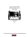
Agilent Technologies 8920B
RF Communications Test Set
User’s Guide
Firmware Version B.06.00 and above
SCREEN CONTROL
INSTRUMENT STATE
MSSG
HELP
CONFI
HOLD
PRINT
ADRS
SAVE
RX
TX
DUPLE
PREV
TESTS
LOCAL
RECAL
USER
DATA FUNCTIONS
k1’
REF
INCR
k1
k2’
METER
INCR
LO
MEAS
PRESE
DATA
AVG
INCR
7
8
9
ENTER
4
5
6
GHz
1
2
3
HI
dB
k2
k3’
CURSOR CON-
k3
ASSIG
k4
RELEA
SHIFT
CANCE
+_
0
PUSH TO
k5
YES
NO
ON/OFF
ppm
Ω
%
%
MHz
s
kHz
ms
Hz
MEMO
RF IN/OUT
DUPLEX OUT
ANT IN
MIC/
VOL-
SQUELC
AUDIO IN
AUDIO
HI
LO
POWE
OF
O
!
MAX POWER
!
!
MAX POWER 200
MAX
!
MAX
Agilent Part No. 08920-90221
Printed in U. S. A.
April 2000
Rev. E
1
Main Menu
© Copyright Agilent Technologies 1996-2000. All Rights Reserved
Notice
No part of this manual may be reproduced in any form or by any means (including
electronic storage and retrieval or translation into a foreign language) without prior
agreement and written consent from Agilent Technologies Inc. as governed by
United States and international copyright laws.
The material contained in this document is subject to change without notice.
Agilent Technologies makes no warranty of any kind with regard to this material,
including, but not limited to, the implied warranties of merchantability and fitness
for a particular purpose. Agilent Technologies Inc. shall not be liable for errors
contained herein or for incidental or consequential damages in connection with the
furnishing, performance, or use of this material.
U.S. Government users will receive no greater than Limited Rights as defined in
FAR 52.227-14 (June 1987) or DFAR 252.227-7015 (b)(2) (November 1995), as
applicable in any technical data.
Agilent Technologies
Learning Products Department
24001 E. Mission
Liberty Lake, WA 99019-9599
U.S.A.
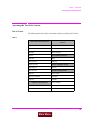
Edition/Print Date
All Editions and Updates of this manual and their creation dates are listed below.
Rev. A . . . . . October 1996
Rev. B . . . . . September 1997
Rev. C . . . . . December 1997
Rev. D . . . . . October 1999
Rev. E . . . . . April 2000
2
Main Menu
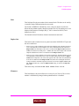
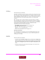
Safety Summary
The following general safety precautions must be observed during all phases of
operation of this instrument. Failure to comply with these precautions or with
specific warnings elsewhere in this manual violates safety standards of design,
manufacture, and intended use of the instrument. Agilent Technologies Inc.
assumes no liability for the customer’s failure to comply with these requirements.
GENERAL
This product is a Safety Class 1 instrument (provided with a protective earth
terminal). The protective features of this product may be impaired if it is used in a
manner not specified in the operation instructions.
All Light Emitting Diodes (LEDs) used in this product are Class 1 LEDs as per IEC
60825-1.
This product has been designed and tested in accordance with IEC Publication
1010, "Safety Requirements for Electronic Measuring Apparatus," and has been
supplied in a safe condition. This instruction documentation contains information
and warnings which must be followed by the user to ensure safe operation and to
maintain the product in a safe condition.
ENVIRONMENTAL CONDITIONS
This instrument is intended for indoor use in an installation category II, pollution
degree 2 environment. It is designed to operate at a maximum relative humidity of
95% and at altitudes of up to 2000 meters. Refer to the specifications tables for the
ac mains voltage requirements and ambient operating temperature range.
Ventilation Requirements: When installing the product in a cabinet, the convection
into and out of the product must not be restricted. The ambient temperature
(outside the cabinet) must be less than the maximum operating temperature of the
product by 4° C for every 100 watts dissipated in the cabinet. If the total power
dissipated in the cabinet is greater than 800 watts, then forced convection must be
used.
BEFORE APPLYING POWER
Verify that the product is set to match the available line voltage, the correct fuse is
installed, and all safety precautions are taken. Note the instrument's external
markings described under Safety Symbols.
3
Main Menu
GROUND THE INSTRUMENT
To minimize shock hazard, the instrument chassis and cover must be connected to
an electrical protective earth ground. The instrument must be connected to the ac
power mains through a grounded power cable, with the ground wire firmly
connected to an electrical ground (safety ground) at the power outlet. Any
interruption of the protective (grounding) conductor or disconnection of the
protective earth terminal will cause a potential shock hazard that could result in
personal injury.
FUSES
Only fuses with the required rated current, voltage, and specified type (normal
blow, time delay, etc.) should be used. Do not use repaired fuses or short-circuited
fuse holders. To do so could cause a shock or fire hazard.
DO NOT OPERATE IN AN EXPLOSIVE ATMOSPHERE
Do not operate the instrument in the presence of flammable gases or fumes.
DO NOT REMOVE THE INSTRUMENT COVER
Operating personnel must not remove instrument covers. Component replacement
and internal adjustments must be made only by qualified service personnel.
Instruments that appear damaged or defective should be made inoperative and
secured against unintended operation until they can be repaired by qualified
service personnel.
WARNING:
The WARNING sign denotes a hazard. It calls attention to a procedure, practice, or
the like, which, if not correctly performed or adhered to, could result in personal
injury. Do not proceed beyond a WARNING sign until the indicated conditions are
fully understood and met.
CAUTION:
The CAUTION sign denotes a hazard. It calls attention to an operating procedure, or the
like, which, if not correctly performed or adhered to, could result in damage to or
destruction of part or all of the product. Do not proceed beyond a CAUTION sign until the
indicated conditions are fully understood and met.
4
Main Menu
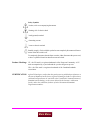
Safety Symbols
Caution, refer to accompanying documents
Warning, risk of electric shock
Earth (ground) terminal
Alternating current
Frame or chassis terminal
Standby (supply). Units with this symbol are not completely disconnected from ac
mains when this switch is off.
To completely disconnect the unit from ac mains, either disconnect the power cord,
or have a qualified electrician install an external switch.
Product Markings CE - the CE mark is a registered trademark of the European Community. A CE
mark accompanied by a year indicated the year the design was proven.
CSA - the CSA mark is a registered trademark of the Canadian Standards
Association.
CERTIFICATION Agilent Technologies certifies that this product met its published specifications at
the time of shipment from the factory. Agilent Technologies further certifies that its
calibration measurements are traceable to the United States National Institute of
Standards and Technology, to the extent allowed by the Institute’s calibration
facility, and to the calibration facilities of other International Standards
Organization members
5
Main Menu
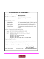
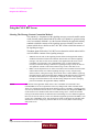
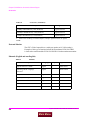
Agilent Technologies Warranty Statement for Commercial Products
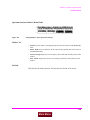
Agilent Technologies 8920B RF Communications Test Set
Duration of
Warranty: 1 year
1. Agilent Technologies warrants Agilent Technologies hardware, accessories and
supplies against defects in materials and workmanship for the period specified above.
If Agilent Technologies receives notice of such defects during the warranty period,
Agilent Technologies will, at its option, either repair or replace products which prove
to be defective. Replacement products may be either new or like-new.
2. Agilent Technologies warrants that Agilent Technologies software will not fail to execute its programming instructions, for the period specified above, due to defects in material and workmanship when properly installed and used. If Agilent Technologies
receives notice of such defects during the warranty period, Agilent Technologies will
replace software media which does not execute its programming instructions due to
such defects.
3. Agilent Technologies does not warrant that the operation of Agilent Technologies
products will be uninterrupted or error free. If Agilent Technologies is unable, within
a reasonable time, to repair or replace any product to a condition as warranted,
customer will be entitled to a refund of the purchase price upon prompt return of the
product.
4. Agilent Technologies products may contain remanufactured parts equivalent to new in
performance or may have been subject to incidental use.
5. The warranty period begins on the date of delivery or on the date of installation if
installed by Agilent Technologies. If customer schedules or delays Agilent
Technologies installation more than 30 days after delivery, warranty begins on the 31st
day from delivery.
6. Warranty does not apply to defects resulting from (a) improper or inadequate maintenance or calibration, (b) software, interfacing, parts or supplies not supplied by Agilent
Technologies, (c) unauthorized modification or misuse, (d) operation outside of the
published environmental specifications for the product, or (e) improper site preparation
or maintenance.
7. TO THE EXTENT ALLOWED BY LOCAL LAW, THE ABOVE WARRANTIES
ARE EXCLUSIVE AND NO OTHER WARRANTYOR CONDITION, WHETHER
WRITTEN OR ORAL IS EXPRESSED OR IMPLIED AND AGILENT TECHNOLOGIES SPECIFICALLY DISCLAIMS ANY IMPLIED WARRANTIES OR CONDITIONS OR MERCHANTABILITY, SATISFACTORY QUALITY, AND FITNESS
FOR A PARTICULAR PURPOSE.
6
Main Menu
8. Agilent Technologies will be liable for damage to tangible property per incident up to
the greater of $300,000 or the actual amount paid for the product that is the subject of
the claim, and for damages for bodily injury or death, to the extent that all such damages are determined by a court of competent jurisdiction to have been directly caused
by a defective Agilent Technologies product.
9. TO THE EXTENT ALLOWED BY LOCAL LAW, THE REMEDIES IN THIS
WARRANTY STATEMENT ARE CUSTOMER’S SOLE AND EXCLUSIVE
REMEDIES. EXCEPT AS INDICATED ABOVE, IN NO EVENT WILL AGILENT
TECHNOLOGIES OR ITS SUPPLIERS BE LIABLE FOR LOSS OF DATA OR FOR
DIRECT, SPECIAL, INCIDENTAL, CONSEQUENTIAL (INCLUDING LOST
PROFIT OR DATA), OR OTHER DAMAGE, WHETHER BASED IN CONTRACT,
TORT, OR OTHERWISE.
FOR CONSUMER TRANSACTIONS IN AUSTRALIA AND NEW ZEALAND:
THE WARRANTY TERMS CONTAINED IN THIS STATEMENT, EXCEPT TO
THE EXTENT LAWFULLY PERMITTED, DO NOT EXCLUDE RESTRICT OR
MODIFY AND ARE IN ADDITION TO THE MANDATORY STATUTORY
RIGHTS APPLICABLE TO THE SALE OF THIS PRODUCT TO YOU.
ASSISTANCE
Product maintenance agreements and other customer assistance agreements are
available for Agilent Technologies products. For any assistance, contact your
nearest Agilent Technologies Sales and Service Office.
7
Main Menu
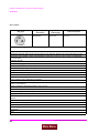
DECLARATION OF CONFORMITY
according to ISO/IEC Guide 22 and EN 45014
Manufacturer’s Name:
Manufacturer’s Address:
Agilent Technologies
24001 E. Mission Avenue
Liberty Lake, Washington 99019-9599
USA
declares that the product
Product Name:
RF Communications Test Set / Cell Site Test Set
Model Number:
Agilent Technologies 8920A, 8920B , and 8921A
Product Options:
This declaration covers all options of the above
product.
conforms to the following Product specifications:
Safety: IEC 1010-1:1990+A1+A2/EN 61010-1:1993
EMC:
CISPR 11:1990 / EN 55011:1991 Group 1, Class A
EN 50082-1 : 1992
IEC 801-2:1991 - 4 kV CD, 8 kV AD
IEC 801-3:1984 - 3V/m
IEC 801-4:1988 - 0.5 kV Sig. Lines, 1 kV Power Lines
Supplementary Information:
This is a class A product. In a domestic environment this product may cause radio interference in
which case the user may be required to take adequate measures.
This product herewith complies with the requirements of the Low Voltage Directive
73/23/EEC and the EMC Directive 89/336/EEC and carries the CD-marking accordingly.
Spokane, Washington USA
Date October 17, 1996
Vince Roland/Quality Manager
8
Main Menu
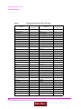
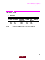
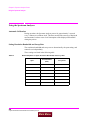
Table 1
Regional Sales Offices
United States of America:
Agilent Technologies
Test and Measurement Call Center
P.O. Box 4026
Englewood, CO 80155-4026
Canada:
Agilent Technologies Canada Inc.
5150 Spectrum Way
Mississauga, Ontario
L4W 5G1
(tel) 1 800 452 4844
(tel) 1 877 894 4414
Europe:
Agilent Technologies
European Marketing Organization
P.O. Box 999
1180 AZ Amstelveen
The Netherlands
(tel) (3120) 547 9999
Japan:
Agilent Technologies Japan Ltd.
Measurement Assistance Center
9-1 Takakura-Cho, Hachioji-Shi,
Tokyo 192-8510, Japan
(tel) (81) 456-56-7832
(fax) (81) 426-56-7840
Latin America:
Agilent Technologies
Latin America Region
Headquarters
5200 Blue Lagoon Drive,
Suite #950
Miami, Florida 33126
U.S. A.
(tel) (305) 267 4245
(fax) (305) 267 4286
Australia/New Zealand:
Agilent Technologies
Australia Pty Ltd.
347 Burwood Highway
Forest Hill, Victoria 3131
Australia
(tel) 1 800 629 485
(fax) (61 3) 9272 0749
New Zealand
(tel) 0 800 738 378
(fax) (64 4) 802 6881
Asia Pacific:
Agilent Technologies
24/F, Cityplaza One,
111 Kings Road,
Taikoo Shing, Hong Kong
(tel) (852) 3197 7777
(fax) (852) 2506 9233
9
Main Menu
Service and
Support
Any adjustment, maintenance, or repair of this product must be performed by
qualified personnel. Contact your customer engineer through your local Agilent
Technologies Service Center. You can find a list of local service representatives on
the Web at:
http://www.agilent-tech.com/services/English/index.html
If you do not have access to the Internet, one of these centers can direct you to your
nearest representative:
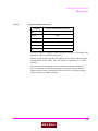
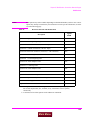
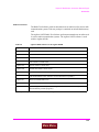
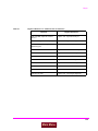
Table 2
United States Test and Measurement Call Center
(Toll free in US)
(800) 452-4844
Europe
(31 20) 547 9900
Canada
(905) 206-4725
Japan Measurement Assistance Center
(81) 426 56 7832
|(81) 426 56 7840 (FAX)
Latin America
(305) 267 4288 (FAX)
Australia/New Zealand
1 800 629 485 (Australia)
0800 738 378 (New Zealand)
Asia-Pacific
(852) 2599 7777
(852) 2506 9285 (FAX)
10
Main Menu
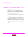
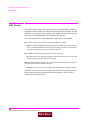
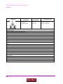
Manufacturer’s
Declaration
This statement is provided to comply with the requirements of the German Sound
Emission Directive, from 18 January 1991.
This product has a sound pressure emission (at the operator position) < 70 dB(A).
•
•
•
•
Sound Pressure Lp < 70 dB(A).
At Operator Position.
Normal Operation.
According to ISO 7779:1988/EN 27779:1991 (Type Test).
Herstellerbescheinigung
Diese Information steht im Zusammenhang mit den Anforderungen der
Maschinenlärminformationsverordnung vom 18 Januar 1991.
•
•
•
•
Schalldruckpegel Lp < 70 dB(A).
Am Arbeitsplatz.
Normaler Betrieb.
Nach ISO 7779:1988/EN 27779:1991 (Typprüfung).
11
Main Menu
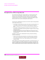
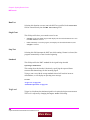
In this Book
The Agilent Technologies 8920B is referred to in this document as the "Test Set."
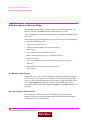
Chapter 1, Get Started
This chapter describes the basic operation of the Test Set. It also provides a quick
check that verifies that the Test Set is operating properly.
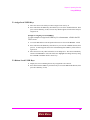
Chapter 2, Configuring Your Test Set
This chapter describes various instrument configuration settings that affect the general
operation of the instrument.
Chapter 3, Operating Overview
This chapter contains detailed operating instructions and examples for using several
instrument features.
Chapters 4 through 23, Screen and Field Descriptions
These chapters contains reference information for each screen and its fields. Many of
the descriptions contain signal flow diagrams that relate the screen’s fields to the functions they perform. The screens are arranged in alphabetical order by title at the top of
the screen; Signaling Encoder and Signaling Decoder are alphabetized by the names
Encoder and Decoder.
Chapter 24, Connector, Key, and Knob Descriptions
This chapter describes the purpose and use of each connector and control.
Chapter 25, Modifications, Accessories, Manuals, Support
This chapter describes retrofit kits, accessories, manuals, and customer support available for your Test Set.
Error Messages
This section discusses error and operating messages.
12
Main Menu
Contents
1 Get Started
Before Connecting a Radio
40
Accessing the Test Set’s Screens 41
Changing A Field’s Setting 43
How do I Verify that the Test Set is Operating Properly?
46
Instrument Functional Diagram 48
13
Main Menu
Contents
2 Configuring Your Test Set
General Operating Information 52
14
Main Menu
Contents
3 Operating Overview
Interaction Between Screens 56
Displaying Measurements
60
Entering and Changing Numbers
66
Printing A Screen 69
Using Measurement Limit Indicators
Averaging Measurements
72
Setting A Measurement Reference
Using Memory Cards
70
73
74
Saving and Recalling Instrument Setups
Using USER Keys
79
83
Setting an RF Generator/Analyzer Offset
Using Remote Control
87
88
15
Main Menu
Contents
4 Adjacent Channel Power Screen
How the Test Set Measures Adjacent Channel Power (ACP)
Field Descriptions 95
16
Main Menu
94
Contents
5 AF Analyzer Screen
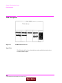
Block Diagram 104
17
Main Menu
Contents
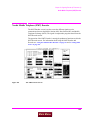
6 Call Processing Subsystem
Description of the Call Processing Subsystem 118
Using the Call Processing Subsystem
122
The CALL CONTROL Screen 126
Using the CALL CONTROL Screen to Test Call Processing
Functions 142
Using the CALL CONTROL Screen to test AMPS
Authentication 152
AUTHENTICATION Screen 163
CALL DATA Screen 166
CALL DATA Screen Message Field Descriptions 171
Using the CALL DATA Screen 188
CALL BIT Screen 197
CALL BIT Screen Message Field Descriptions 204
Using the CALL BIT Screen 248
ANALOG MEAS Screen 253
Using the ANALOG MEAS Screen 256
CALL CONFIGURE Screen 259
18
Main Menu
Contents
7 Configure Screen
Field Descriptions 262
19
Main Menu
Contents
8 Signaling Decoder Screen
Field Descriptions for Decoder Modes 276
AMPS-TACS, NAMPS-NTACS Decoder
277
Using the AMPS/TACS, NAMPS/NTACS Decoder 282
Continuous Digital Controlled Squelch System Decoder
Using the CDCSS Decoder 290
Digital Paging Decoder
291
Dual-Tone Multi-Frequency (DTMF) Decoder
Using the DTMF Decoder 300
EDACS Decoder
301
Using the EDACS Decoder 304
Function Generator Decoder 307
Using the Function Generator Decoder 310
LTR Decoder
311
Using the LTR Decoder 315
MPT 1327 Decoder
317
NMT Decoder 322
Using the NMT Decoder/Encoder
Creating NMT Tests
332
Tone Sequence Decoder
341
20
Main Menu
327
295
286
Contents
9 Duplex Test Screen
Block Diagram 346
Field Descriptions 347
21
Main Menu
Contents
10 Signaling Encoder (AF Generator 2)
Field Descriptions for Encoder Modes 360
AMPS-TACS NAMPS-NTACS Encoder
361
Using the AMPS-TACS, NAMPS-NTACS Encoder 374
CDCSS Encoder
375
Using the CDCSS Encoder 379
Digital Paging Encoder
380
DTMF Sequence Encoder
EDACS Encoder
385
389
Using the EDACS Encoder 395
Function Generator Encoder
LTR Encoder
400
403
Using the LTR Encoder 407
MPT 1327 Encoder
411
Using the MPT 1327 Encoder 424
Nordic Mobile Telephone (NMT) Encoder
Tone Sequence Encoder
439
22
Main Menu
427
Contents
11 Help Screen
Field Descriptions 444
23
Main Menu
Contents
12 I/O Configure Screen
Field Descriptions 446
24
Main Menu
Contents
13 Message Screen
Field Descriptions 452
25
Main Menu
Contents
14 Oscilloscope Screen
Field Descriptions 454
Using the Oscilloscope 461
26
Main Menu
Contents
15 Print Configure Screen
Field Descriptions 464
27
Main Menu
Contents
16 Radio Interface Screen
Radio Interface Functional Description 468
Field Descriptions 470
Using the Radio Interface (Manual Operation) 473
Using The Radio Interface (Remote Operation) 479
28
Main Menu
Contents
17 RF Analyzer Screen
Block Diagram 482
Field Descriptions 483
29
Main Menu
Contents
18 RF Generator Screen
Block Diagram 494
Field Descriptions 495
30
Main Menu
Contents
19 RX Test Screen
Block Diagram 504
Field Descriptions 505
31
Main Menu
Contents
20 Service Screen
Field Descriptions 512
32
Main Menu
Contents
21 Spectrum Analyzer Screen
Field Descriptions 516
Using the Spectrum Analyzer 528
33
Main Menu
Contents
22 Tests Screen
Description of the Tests Subsystem 530
TESTS (Main Menu)
532
TESTS (Channel Information)
TESTS (Test Parameters)
TESTS (Order of Tests)
535
537
538
TESTS (Pass/Fail Limits)
540
TESTS (Save/Delete Procedure)
TESTS (Execution Conditions)
TESTS (External Devices)
TESTS (Printer Setup)
545
548
551
TESTS (IBASIC Controller)
ROM Programs
542
556
34
Main Menu
554
Contents
23 TX Test Screen
Block Diagram 560
Field Descriptions 561
35
Main Menu
Contents
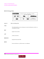
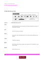
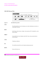
24 Connector, Key, and Knob Descriptions
Connector Descriptions
Key Descriptions
Knob Descriptions
572
590
594
36
Main Menu
Contents
25 Modifications, Accessories, Manuals Support
Modifications
596
Accessories 599
Agilent Technologies Support for Your Instrument
609
37
Main Menu
Contents
Index 625
38
Main Menu
1
Get Started
39
Main Menu
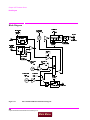
Chapter 1, Get Started
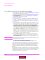
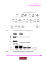
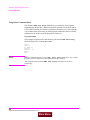
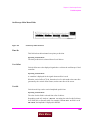
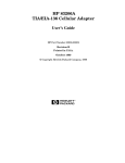
Before Connecting a Radio
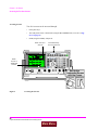
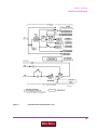
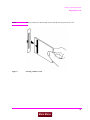
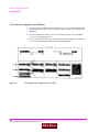
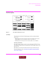
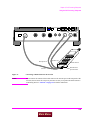
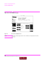
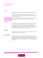
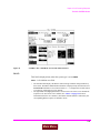
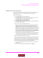
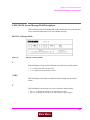
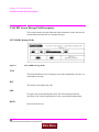
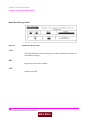
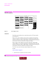
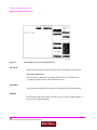
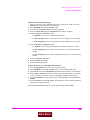
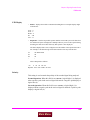
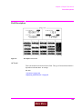
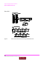
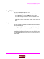
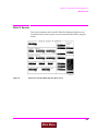
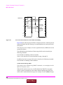
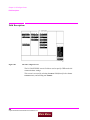
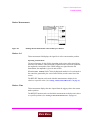
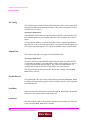
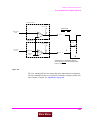
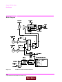
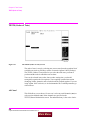
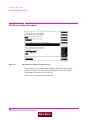
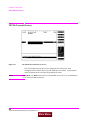
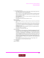
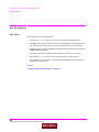
Before Connecting a Radio
The RF IN/OUT port should be used for all transmitter tests when the radio is connected
directly to the Test Set. (All UUT transmitter power measurements are made through this
port). Off-the-air measurements can be made using the ANT IN port.
CAUTION:
Overpower Damage — Refer to the Test Set’s front panel for maximum input power level.
Exceeding this level can cause permanent instrument damage.
INSTRUMENT STATE
SCREEN CONTROL
HELP
MSSG
RX TEST
SINAD
RX
AC Level
dB
TX
RF Gen Freq AFGen1 Freq AF Gen2 Freq Filter 1
1.0000
Amplitude
-80.0
1.0000
kHz
50Hz HPF
AFGEN2 To
FM
FM
Off
On/Off
To Screen
RF GEN
RF ANL
AF ANL
SCOPE
SPEC ANL
ENCODER
DECODER
RADIO INT
kHz
AFGEN1 To
dBm
Atten Hold
Filter 2
15kHz LPF
Off
kHz
Ext Load R
Output Port
PRINT
ADRS
SAVE
PREV
TESTS
LOCAL
RECALL
MEAS
RESET
9
ENTER
6
GHv
dBm
DATA FUNCTIONS
k1’
MHz
HOLD
DUPLEX
PRESET
V
USER
100.000000
CONFIG
REF SET METER
k1
ENTER
INCR
-10
k2’
LO LIMIT
DATA
AVG
INCR
SET
INCR
X10
k3’
CURSOR CONTROL
ASSIGN
k4
More
E
F
4
5
B
C
1
2
dB
A
RELEASE
8.00
RF Out/Dupl
8
HI LIMIT
k2
k3
7
0
PUSH TO SELECT
k5
.
D
%
3
MHv
V
EEX
s
+/ _
kHv
mV
NO
SHIFT
CANCEL
ms
ppm
W
ON/OFF
%
dBuV
Hz
uV
MEMORY
CARD
RF IN/OUT
POWER
0
OFF
DUPLEX OUT
ANT IN
MIC/ACC
VOLUME
SQUELCH
AUDIO OUT
AUDIO IN
HI
LO
0
ON
!
MAX PWR 60W
CONTINUOUS
!
MAX POWER 200mW
!
MAX
12 V PK
MAX
! 42 V PK
20nobug.ds4
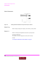
Antenna
Mic Key
Mic Audio In
Radio Under Test
Figure 1
Connecting a Radio to the Test Set
40
S:\agilent\8920\8920b\USRGUIDE\BOOK\CHAPTERS\getstart.fb
Main Menu
Speaker or Audio Out
Chapter 1, Get Started
Accessing the Test Set’s Screens
Accessing the Test Set’s Screens
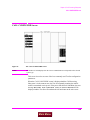
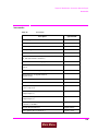
List of Screens
The following table lists all the screens that could be provided by the Test Set.
Table 3
Analog Measurement Screens
Instrument Configuration
Screens
Adjacent Channel Power
Configure
AF Analyzer
I/O Configure
Decoder
Print Configure
Duplex
User Assistance Screens
Encoder
Help
Oscilloscope
Message
Radio Interface
Service Assistance Screen
RF Analyzer
Service
RF Generator
Call Processing Screens
RX Test
Call Control
Spectrum Analyzer
Call Data
TX Test
Call Bit
Software Control Screens
Call Configure
Tests
Analog Measure
Tests (IBASIC Controller)
Authentication
41
Main Menu
Chapter 1, Get Started
Accessing the Test Set’s Screens
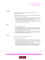
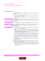
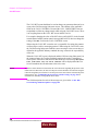
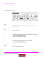
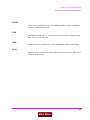
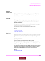
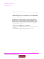
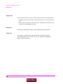
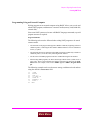
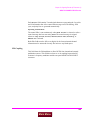
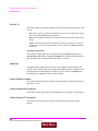
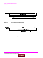
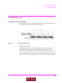
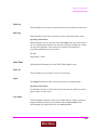
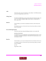
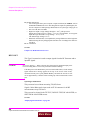
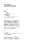
Accessing Screens
Test Set’s screens can be accessed through
•
Front-panel keys
•
The front-panel Cursor Control knob (using the To Screen menu, see item 5 in Figure 3 on page 43)
•
GPIB, using the DISPlay subsystem.
Knob Access to
Screens
Front-Panel Key
Access to Screens
INSTRUMENT STATE
SCREEN CONTROL
MSSG
RX TEST
SINAD
RX
AC Level
dB
k1’
RF Gen Freq
AFGen1 Freq AF Gen2 Freq Filter 1
1.0000
100.000000
MHz
1.0000
kHz
AFGEN1 To
Amplitude
FM
-80.0
dBm
Atten Hold
50Hz HPF
kHz
Filter 2
AFGEN2 To
15kHz LPF
FM
Off
Off
kHz
Ext Load R
On/Off
Output Port
TX
CONFIG
HOLD
PRINT
ADRS
SAVE
DUPLEX
PREV
TESTS
LOCAL
RECALL
MEAS
RESET
9
ENTER
GHv
dBm
PRESET
V
USER
Knob
Access to
Additional
Screens
HELP
To Screen
RF GEN
RF ANL
AF ANL
SCOPE
SPEC ANL
ENCODER
DECODER
RADIO INT
INCR
-10
k2’
LO LIMIT
DATA
AVG
INCR
SET
INCR
X10
7
8
E
F
4
5
6
B
C
D
%
ASSIGN
1
2
3
MHv
V
k4
A
HI LIMIT
k2
k3’
CURSOR CONTROL
k3
RELEASE
8.00
RF Out/Dupl
DATA FUNCTIONS
REF SET METER
k1
ENTER
More
0
PUSH TO SELECT
k5
dB
.
EEX
s
+/_
kHv
mV
NO
SHIFT
CANCEL
ms
%
dBuV
ppm
W
ON/OFF
Hz
uV
MEMORY
CARD
RF IN/OUT
DUPLEX OUT
ANT IN
MIC/ACC
VOLUME
SQUELCH
AUDIO OUT
POWER
AUDIO IN
HI
0
0
OFF
ON
!
MAX PWR 60W
CONTINUOUS
!
MAX POWER 200mW
!
MAX
12 V PK
LO
MAX
! 42 V PK
20nobug.ds4
Figure 2
Accessing the Screens
42
S:\agilent\8920\8920b\USRGUIDE\BOOK\CHAPTERS\getstart.fb
Main Menu
Chapter 1, Get Started
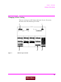
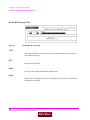
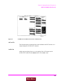
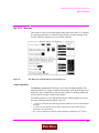
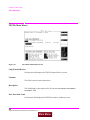
Changing A Field’s Setting
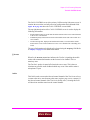
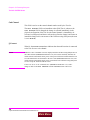
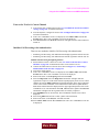
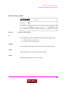
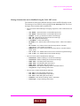
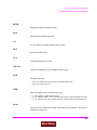
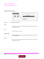
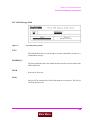
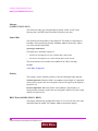
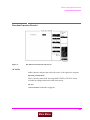
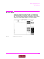
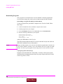
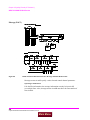
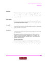
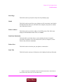
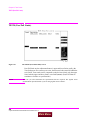
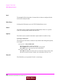
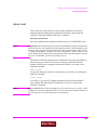
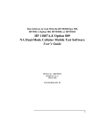
Changing A Field’s Setting
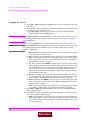
There are several types of CRT display fields in the Test Set. This section
describes some of the different types of fields.
3
1
rxscrn.wmf
intro4.wmf
2
Figure 3
4
5
Different Types of Fields
43
Main Menu
Chapter 1, Get Started
Changing A Field’s Setting
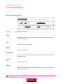
Unit-of-Measure Field
Unit-of-measure can be changed to display measurements in different values or
magnitudes. See item 1 in Figure 3 to see an example of a units-of-measure field.
To change a unit-of-measure
1. Position the cursor at the unit field on the display.
2. Press a key labeled with a different unit-of-measure (such as W).
If the new units are valid, the measurement value is displayed in the unit.
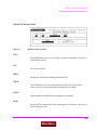
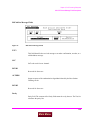
Underlined Immediate-Action Field
Underlined immediate action fields provide a choice of two settings. See item 2 in
Figure 3 to see an example of an underlined immediate-action field.
To change an underlined entry
1. Position the cursor at the field.
2. Push the CURSOR CONTROL knob or the ENTER key to move the underline under
the desired choice.
The underlined setting is immediately activated when selected.
44
S:\agilent\8920\8920b\USRGUIDE\BOOK\CHAPTERS\getstart.fb
Main Menu
Chapter 1, Get Started
Changing A Field’s Setting
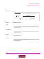
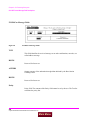
One-of-Many Field
One-of-many fields display a list of choices when selected. See item 3 in Figure 3
to see an example of a one-of many field.
To make a one-of-many choice
1. Position the cursor at the field.
2. Push the Cursor Control knob or the ENTER key to display the choices.
3. Move the cursor through the choices by turning the knob.
4. Push the Cursor Control knob or the ENTER key to make the choice.
The choice is immediately activated when selected.
The To Screen menu (see item 5 in Figure 3) is a variation of the one-of-many
field.
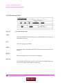
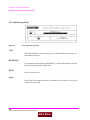
Numeric-Entry Field
Numeric-entry fields contain values for settings like External Load Resistance and
RF Generator Frequency.See item 4 in Figure 3 to see an example of a numericentry field.
To change a value
1. Position the cursor at the field.
2. Key in the desired number using the DATA keys.
3. Press ENTER to select the choice.
OR
1.
2.
3.
4.
Position the cursor at the field.
Push the Cursor Control knob to highlight the desired choice.
Turn the knob to increment or decrement the value.
Push the Cursor Control knob or the ENTER key to select the choice.
45
Main Menu
Chapter 1, Get Started
How do I Verify that the Test Set is Operating Properly?
How do I Verify that the Test Set is Operating Properly?
If your Test Set powers-up and displays the RX TEST screen, but you suspect an
instrument problem, use the Instrument Quick Check to verify operation of the
basic instrument functions.
If no failure is indicated by this test, but you still suspect a problem, refer to the
“Performance Tests” information in the Assembly Level Repair Manual.
46
S:\agilent\8920\8920b\USRGUIDE\BOOK\CHAPTERS\getstart.fb
Main Menu
Chapter 1, Get Started
How do I Verify that the Test Set is Operating Properly?
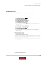
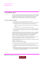
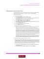
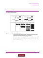
Instrument Quick Check
1.
Set up the quick check:
a.
b.
c.
d.
e.
f.
g.
h.
i.
j.
k.
l.
m.
n.
o.
p.
q.
Connect a cable between the DUPLEX OUT and ANT IN ports.
Turn instrument power on (if it is not already on).
Press PRESET.
Press DUPLEX to access the DUPLEX TEST screen.
Set the Tune Mode field to Manual.
Set the Tune Freq field to 825 MHz.
Set the Input Port field to Ant.
Set the RF Gen Freq field to 825 MHz.
Set the Amplitude field to -10 dBm.
Set the Output Port field to Dupl.
Verify that AFGen1 Freq is set to 1.0000 kHz, and that AFGen1 To is set to
FM and 3.00 kHz.
Set the AF Anl In field to FM Demod.
Set the Filter 1 field to 300Hz HPF.
Set the Filter 2 field to 3kHz LPF.
Verify that De-Emphasis is Off.
Set the Detector field to Pk+-/2.
Turn the VOLUME knob clockwise until you hear a tone (1 kHz default for
AFGen1 Freq).
2. Check the following readings:
❒ SINAD should be >35 dB.
❒ FM Deviation should be about 3.0 kHz.
3
Access the OSCILLOSCOPE screen using the To Screen menu. With the default
Vert/div setting of 2 kHz and a default Time/div setting of 200 µs, you should
see two complete sinewaves across the screen.
4
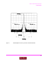
Access the SPECTRUM ANALYZER1 using the To Screen menu. You should see
an 825 MHz FM carrier.
1.
Optional on some Test Set models.
47
Main Menu
Chapter 1, Get Started
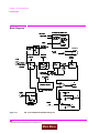
Instrument Functional Diagram
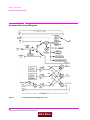
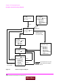
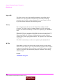
Instrument Functional Diagram
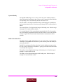
Figure 4
Instrument Functional Diagram (1 of 2)
48
S:\agilent\8920\8920b\USRGUIDE\BOOK\CHAPTERS\getstart.fb
Main Menu
Chapter 1, Get Started
Instrument Functional Diagram
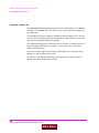
intr-bd2.wmf
Figure 5
Instrument Functional Diagram (2 of 2)
49
Main Menu
Chapter 1, Get Started
Instrument Functional Diagram
50
S:\agilent\8920\8920b\USRGUIDE\BOOK\CHAPTERS\getstart.fb
Main Menu
2
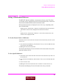
Configuring Your Test Set
The CONFIGURE and I/O CONFIGURE screens contain a number of settings used to
alter instrument operation and hardware communication settings. The GPIB address,
screen intensity, serial communication parameters, and several other settings, are changed
in these screens.
Most CONFIGURE and I/O CONFIGURE screen entries are saved when the instrument
is turned off.
51
Main Menu
Chapter 2, Configuring Your Test Set
General Operating Information
General Operating Information
The following configuration information discusses general operating information
for some of the fields in these screens.
To Set Screen Intensity
1. Access the CONFIGURE screen.
2. Select the Intensity field.
3. Rotate the knob to change the setting (1=dim, 8=bright).
To Set RF Voltage Interpretation (50 Ω /emf)
1. Access the CONFIGURE screen.
2. Position the cursor in front of the RFGen Volts field.
3. Press the Cursor Control knob or press ENTER to select 50 ohm or emf.
Voltage settings can control either:
•
the voltage across a 50-ohm load, or
•
the open circuit voltage (emf).
This setting affects the RF Generator’s and the Tracking Generator’s amplitudes.
To Set the Date and Time
1. Access the CONFIGURE screen.
2. Select the Date field and use the DATA keys to enter the date in the format shown below the field.
3. Select the Time field and use the DATA keys to enter the time in the format shown
below the field.
The Test Set has a built-in clock that keeps track of the date and time. It is
powered by an internal battery to keep it operating when the instrument is off.
52
S:\agilent\8920\8920b\USRGUIDE\BOOK\CHAPTERS\configts.fb
Main Menu
Chapter 2, Configuring Your Test Set
General Operating Information
To Change the Beeper Volume
1. Access the CONFIGURE screen.
2. Select the Beeper field to display the volume choices.
3. Select the desired choice.
The beeper alerts you to important operating and measurement conditions. It
beeps any time a message is displayed at the top of the screen. These messages
warn you of conditions such as exceeding the RF input level or trying to set a field
to an unacceptable value. Therefore, it is recommended that you do not disable the
beeper.
To Verify or Change the
Low-Battery Setting
1. Access the CONFIGURE screen.
2. The current time setting is shown under the Low Battery field.
3. Select that field to display a list of setting choices.
•
Select the desired time, or
•
Select Disable to eliminate the low-battery warning.
The low-battery warning system is used to alert you when you have not used any
front-panel controls within a specified amount of time. This setting is only used
with DC power. It does not actually monitor the DC supply voltage. Since
batteries are most often used for a DC supply, this function helps you conserve
power by reminding you that the Test Set is still turned on.
When the specified time has elapsed between front-panel entries, the Beeper
sounds and a message appears at the top of the screen alerting you to the
condition.
This setting is saved when the instrument is turned off.
53
Main Menu
Chapter 2, Configuring Your Test Set
General Operating Information
54
S:\agilent\8920\8920b\USRGUIDE\BOOK\CHAPTERS\configts.fb
Main Menu
3
Operating Overview
The information in this section discusses some frequently used operating features
of the Test Set.
From reading Chapter 1, “Get Started,” you should understand:
•
•
What “fields” and “screens” are.
How to use the Cursor Control knob to select different fields and screens.
55
Main Menu
Chapter 3, Operating Overview
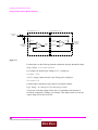
Interaction Between Screens
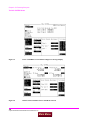
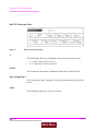
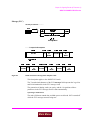
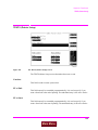
Interaction Between Screens
Most fields operate globally; changing the setting in any screen automatically
changes that setting in all screens where it is available. AFGen1 Freq is an
example of this field type.
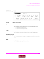
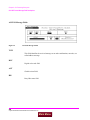
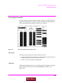
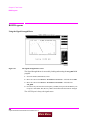
Figure 6
Example of How Global Fields Work
Priority fields give the RX TEST and TX TEST screens priority control of their
settings. No matter what these fields were set to in other screens, if the RX TEST
or TX TEST screen is accessed, the field changes to whatever it was last set to in
these screens. The RF Generator’s Amplitude field is an example of this field
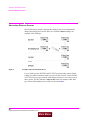
type. These fields and their preset values are listed in Table 4.
56
S:\agilent\8920\8920b\USRGUIDE\BOOK\CHAPTERS\opoverv.fb
Main Menu
Chapter 3, Operating Overview
Interaction Between Screens
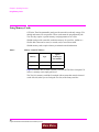
Table 4
Priority RX TEST and TX TEST Fields
Priority Field
RX TEST
TX TEST
RF Gen Amplitude
Presets to −80 dBm (changeable)
Always Off
AFGen1 To
Presets to FM (changeable)
Always Audio Out
AF Anl In
Always Audio In
Presets to FM Demod (changeable)
Detector
Always RMS
Presets to Pk +− Max (changeable)
De-emphasis
Always Off
Presets to 750 µs (changeable)
AF Anl Measurement
Presets to SINAD (changeable)
Presets to Audio Freq (changeable)
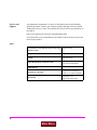
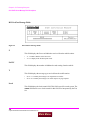
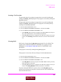
Using your Test Set, duplicate the steps in Figure 7 to demonstrate how the
Priority fields operate.
57
Main Menu
Chapter 3, Operating Overview
Interaction Between Screens
fig2-2.wmf
Figure 7
Example of How Priority Fields Work
58
S:\agilent\8920\8920b\USRGUIDE\BOOK\CHAPTERS\opoverv.fb
Main Menu
Chapter 3, Operating Overview
Interaction Between Screens
Priority CALL CONFIGURE Field
The Input Att field located on the CALL CONFIGURE screen is another
priority field. Similar fields labeled Input Atten are located on the
ADJACENT CHANNEL POWER screen, RF ANALYZER screen, and the
SPECTRUM ANALYZER screen.
Setting the Input Att field from the CALL CONFIGURE screen updates all
Input Atten fields found on the other screens. Setting the Input Atten field
updates all other Input Atten fields but does not change the setting of the
Input Att field. Accessing the CALL CONFIGURE screen changes the input
attenuator to the current value of the Input Att field and updates all Input
Atten fields.
59
Main Menu
Chapter 3, Operating Overview
Displaying Measurements
Displaying Measurements
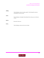
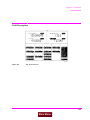
scntxrx.wmf
Figure 8
Where To Access Measurements
60
S:\agilent\8920\8920b\USRGUIDE\BOOK\CHAPTERS\opoverv.fb
Main Menu
Chapter 3, Operating Overview
Displaying Measurements
Displaying RF Measurements
Transmitter Frequency
TX Frequency is displayed when Tune Mode is set to Auto. (Refer to item (1)
in Figure 8 on page 60.)
Transmitter Frequency Error
TX Freq Error is displayed when Tune Mode is set to Manual. (Refer to item
(1) in Figure 8 on page 60.)
Transmitter Power
TX Power is only measured and displayed here when the Input Port is set to
RF In (Refer to item (2) in Figure 8 on page 60). If Ant (antenna) is selected, the
measurement is replaced by four dashes (- - - -).
You can measure low power levels on the ANT IN port using the Spectrum
Analyzer.1
Refer to “TX Power” on page 569 and “TX Pwr Zero” on page 570 for more
information on measuring transmitter power.
CAUTION:
Connecting a signal of >200 mW to the ANT IN (antenna) port can cause instrument damage
(although internal protection circuits can typically withstand a short-duration signal of 1 or 2
Watts). If the overpower circuit is triggered, remove the signal from the ANT IN port and turn
the Test Set off and on to reset it.
1.
Optional on some Test Set models.
61
Main Menu
Chapter 3, Operating Overview
Displaying Measurements
Displaying AF Measurements
FM Deviation, AM Depth, AC Level
The AF Anl In setting determines the AF Analyzer’s input and the measurement
displayed in the top-right corner of the measurement area (see Table 5). These
measurements are available in the TX TEST, DUPLEX TEST, RF GENERATOR,
RF ANALYZER, and AF ANALYZER screens. (Refer to item (3) in Figure 8 on
page 60.)
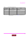
Table 5
AF Measurements Selected by AF Analyzer Input Setting
Measurement
AF Anl In Setting
FM Deviation
FM Demod, FM Mod
AM Depth
AM Demod, AM Mod
AM Deptha
SSB Demod, AudioIn, Radio Int,
Ext Mod, Mic Mod, Audio Out
a. AC Level is also measured in the RX TEST screen, but
always uses the AUDIO IN connector as the input. (Refer
to item (5) in Figure 8 on page 60.)
62
S:\agilent\8920\8920b\USRGUIDE\BOOK\CHAPTERS\opoverv.fb
Main Menu
Chapter 3, Operating Overview
Displaying Measurements
SINAD, Distortion, SNR, AF Frequency, DC Level, DC Current
Selecting the currently-displayed measurement causes the To Screen menu to be
replaced by a list of measurement choices. Select the new choice to replace the old
measurement. These measurements are available in the RX TEST, TX TEST,
DUPLEX TEST, RF GENERATOR, RF ANALYZER, and AF ANALYZER
screens. (Refer to item (4) in Figure 8 on page 60)
The Distortion measurement is only for a 1 kHz tone.
The SINAD measurement is normally shown using an analog-type meter and
small digits, but can be changed to display in large digits only. (See “To Use the
Analog METER Format” on page 65.)
DC Current can only be measured using the rear-panel DC CURRENT
MEASUREMENT connections.
Selecting SNR (Signal/Noise Ratio) turns off the other audio measurement. For
more information on making this measurement, see “RF Gen Freq” on page 509.
AF Power
AF Power is measured in the RX TEST screen by specifying the external load
resistance, Ext Load R, and changing the unit of measure for the AC Level
measurement to W (Watts), mW, or dBm. (The milliwatt (mW) unit is selected by
pressing SHIFT, ENTER) Refer to item (5) Figure 8 on page 60.
63
Main Menu
Chapter 3, Operating Overview
Displaying Measurements
To Change the Measurement’s Unit-of-Measure
1. Position the cursor in front of the present unit-of-measurement.
2. Press the key labeled with the desired unit.
All measurements allow you to change the associated unit-of- measure. For
instance; the TX Power measurement is usually displayed in Watts, but can be
changed to display in mW, dBm, V, mV, or dBµV.
Select mW by pressing SHIFT, ENTER.
For example; to display transmitter power in units of dBm instead of Watts:
1. Move the cursor in front of the unit-of-measure for the TX Power measurement (W).
2. Press the dBm key. The measurement value is changed immediately to display in dBm.
64
S:\agilent\8920\8920b\USRGUIDE\BOOK\CHAPTERS\opoverv.fb
Main Menu
Chapter 3, Operating Overview
Displaying Measurements
To Use the Analog METER Format
To display measurement results using the analog meter format, use the following
procedure.
1. Position the cursor in front of the unit-of-measure for the measurement you want to display.
2. Press and release the SHIFT key, then the INCR SET key to display the Meters menu
in the lower-right corner of the screen.
3. Select On/Off to display the meter.
4. Repeat steps 1 and 2 to enter each meter end point and the meter intervals.
5. Repeat steps 1, 2, and 3 to cancel the METER function.
The METER function displays an equivalent analog display. (This is the SINAD
measurement’s default state when the instrument is turned on or preset). As the
measurement is displayed graphically on the meter, the value is also displayed in
small digits below the meter.
You can specify the high and low end points and display interval, or you can use
the default meter settings.
This function is only available for measurements displayed using the large digits,
such as the measurements displayed in the RX TEST and TX TEST screens.
To Make Beat Frequency Measurements
1. Select the DUPLEX TEST screen to set up for beat frequency oscillator measurements.
2. Set the AF Anl In field to SSB Demod.
3. Manually adjust the Tune Freq field to the desired carrier frequency.
65
Main Menu
Chapter 3, Operating Overview
Entering and Changing Numbers
Entering and Changing Numbers
Values for numeric entry fields can be entered and changed using various
methods, depending on your testing needs. The unit-of-measure for some of these
fields can also be changed (such as changing the RF Generator’s Amplitude
units from dBm to µV).
To Enter Numbers
1. Position the cursor in front of the numeric entry field to be changed.
2. Use one of the following methods:
a. enter the number and unit-of-measure directly using the keypad,
or
b. press the Cursor Control knob or ENTER to highlight the field, and use the
knob,
or
c. use the down-arrow or the up-arrow keys to increment or decrement the present
value.
Decimal Values
Decimal values are used for most numeric entry fields, such as the RF Gen Freq
setting. The acceptable entries for decimal values are 0 through 9, ., +/-, and EEX.
The +/- key is used for entering negative numbers. For example; when entering
the RF Generator Amplitude you can enter this sequence to set the value to
−47 dBm: +/- 4 7 dBm.
The EEX key can be used when entering exponential notation. For example; to
enter 1.25 × 10³ kHz you could use the sequence: 1 . 2 5 EEX 3 kHz.
66
S:\agilent\8920\8920b\USRGUIDE\BOOK\CHAPTERS\opoverv.fb
Main Menu
Chapter 3, Operating Overview
Entering and Changing Numbers
Hexadecimal Values
Hexadecimal (Hex) values are used for entering some signaling parameters in the
ENCODER, such as AMPS Filler data field, and for specifying remote
communications parameters, such as the RADIO INTERFACE Output Data
field. The acceptable entries for decimal values are 0 through 9 and A through F.
No unit-of-measure is associated with these values.
Hexadecimal values are either entered from the keypad (A through F are shifted
functions), or by using the Choices menu displayed when certain fields are
selected (such as the AMPS Filler field).
To Enter and Change the Unit-of-Measure
Entering the Unit-of-Measure for Settings
When a number is entered, the unit-of-measure is either specified or implied.
When the unit is implied, the current unit is used. For example; if the present RF
frequency is 250 MHz, and you want to change it to 225 MHz, you would enter
this sequence: 2 2 5 ENTER.
When the unit is specified, the units change to whatever you specify. For example;
if the present RF Gen Freq setting is 250 MHz, and you want to change it to 455
kHz, you would enter this sequence: 4 5 5 kHz.
Changing the Unit-of-Measure for Settings
To change the present unit-of-measure, position the cursor in front of the field and
press the key labeled with the desired unit. For example, position the cursor in
front of the RF Gen Freq field and push GHz or kHz to display the setting in
either of these units.
67
Main Menu
Chapter 3, Operating Overview
Entering and Changing Numbers
To Change the Increment or Decrement Setting
Using the Pre-Defined Increment/Decrement Keys
The INCR ×10] and INCR ÷10] keys change the increment/decrement value by a
factor of 10.
For example; if the Tune Freq presently changes by 10 MHz for every click of
the knob or push of the down-arrow or up-arrow keys, pushing INCR ×10] once
changes the increment value to 100 MHz.
Specifying An Increment Value
The INCR SET key is used to assign a specific increment value. The increment
value may use different units than the field you are incrementing/decrementing.
For instance; if the RF Generator Amplitude setting is displayed in dBµV, you
could increment in units of dB or mV.
To change the increment value;
1. Move the cursor to the numeric entry field to be changed.
2. Press INCR SET, and enter the desired value and unit-of-measure using the DATA keys.
3. Use the down-arrow and up-arrow keys or CURSOR CONTROL knob to change the
field’s value by the increment value you set.
Example of Setting an Increment Value
This example changes the Tune Freq in increments of 15 MHz.
1. Access the TX TEST screen and position the cursor in front of the Tune Freq field.
2. Press 1 0 0 MHz to set the frequency at 100 MHz.
3. Press INCR SET 1 5 MHz.
4. Turn the Cursor Control knob. The field’s value changes by 15 MHz for each knob
click.
68
S:\agilent\8920\8920b\USRGUIDE\BOOK\CHAPTERS\opoverv.fb
Main Menu
Chapter 3, Operating Overview
Printing A Screen
Printing A Screen
To Print A Screen’s Contents
1. Connect a printer to the appropriate rear-panel connector.
2. Access the PRINT CONFIGURE screen from the More menu and set the Printer
Port field to the appropriate type of printer connection.
•
If HP-IB is selected, enter the GPIB Printer Address of the printer.
3. Select the type of printer you are using in the Model field. If your printer is not listed,
configure your printer to emulate one that is listed.
4. Enter a Print Title using the knob, if desired. This text will appear at the top of
your printout.
5. Display the screen you want to print and press and release the SHIFT key, then the
TESTS key to access the PRINT function.
To interrupt printing, select the Abort Print field on the PRINT CONFIGURE
screen.
69
Main Menu
Chapter 3, Operating Overview
Using Measurement Limit Indicators
Using Measurement Limit Indicators
The LO LIMIT and HI LIMIT functions are used to define a measurement
“window” to alert you to measurements that are outside these limits. When limits
are assigned, Lo and/or Hi appear by the measurement.
A measurement that goes above or below the defined limits causes three things to
happen:
1. A message appears at the top of the screen indicating a limit was exceeded.
2. The Lo or Hi indicator by the measurement flashes.
3. The Beeper beeps if it is has been enabled in the CONFIGURE screen.
Limits are helpful when you can’t watch the Test Set’s display while you are
making an adjustment on the equipment you are testing or repairing. They are also
a convenient way of alerting you to long-term measurement drift without having
to observe the screen.
To Set A HI and/or LO LIMIT
1. Position the cursor in front of the unit-of-measure for the measurement that you are setting limits for.
2. Press and release the SHIFT key, then the down-arrow key to access the LO LIMIT
function, and enter the measurement’s low-limit value and its unit-of-measure.1
3. Press and release the SHIFT key, then the up-arrow key to access the HI LIMIT function, and enter the measurement’s high-limit value and its unit-of-measure.1
1. The fundamental unit for the LIMITs does not have to be the same as the measurement’s units. For instance; when measuring AC Level in Volts, you can set HI and LO
LIMITs in units of dBm.
70
S:\agilent\8920\8920b\USRGUIDE\BOOK\CHAPTERS\opoverv.fb
Main Menu
Chapter 3, Operating Overview
Using Measurement Limit Indicators
To Reset or Remove Limits
To reset a limit that has been exceeded
1. Position the cursor in front of the measurement’s unit-of-measure.
2. Press and release the SHIFT key, then the down-arrow (or up-arrow key) to access the
LO LIMIT (or HI LIMIT) function, then press ENTER or MEAS RESET.
To remove a limit
1. Position the cursor in front of the unit-of-measure for the assigned limit.
2. Press and release the SHIFT key, then the down-arrow (or up-arrow key) to access the
LO LIMIT (or HI LIMIT) function, then press ON/OFF.
Example of Setting HI and LO LIMITs
This example sets limits for the TX Freq Error measurement. Limits are being
set to indicate if a 100 MHz carrier varies more than ± 10 kHz.
1. Position the cursor in front of the unit-of-measure for the TX FREQ ERROR measurement (the default is kHz).
2. Press and release the SHIFT key, then the down-arrow to access the LO LIMIT function, then enter 1 0 kHz.
3. Press and release the SHIFT key, then the up-arrow to access the HI LIMIT function,
then enter 1 0 kHz.
71
Main Menu
Chapter 3, Operating Overview
Averaging Measurements
Averaging Measurements
The AVG (average) function allows you to display the average value of a number
of measurements. You enter the number of measurement samples used to calculate
and display the measurement average. This dampens the effects of rapidly
changing measurements, providing a more usable measurement display.
To Use Measurement Averaging
1. Position the cursor in front of the measurement’s unit-of-measure.
2. Press and release the SHIFT key, then the INCR ×10 key to access the AVG function.
The default number of average samples is displayed below the measurement.
•
Enter the desired number of measurement samples to be used for calculating the average, or
•
Press ON/OFF to use the currently-displayed number of samples.
3. To turn averaging off, position the cursor in front of the unit-of-measure and press and
release the SHIFT key, then the INCR ×10 key to access the AVG function, then press
the ON/OFF key.
When the averaging function is first enabled, a numeric average is calculated and
displayed each time a measurement is made. This continues until the specified
number of samples is reached. From that point on, the averaging function
performs an exponential filtering operation that mimics an RC filter.
Because of the exponential response, any large measurement changes result in a
displayed value that ramps up or down to the actual measured value.
Pressing MEAS RESET clears the measurement history for all measurements and
starts the averaging process over.
Example of Using Measurement Averaging
This example enables the SINAD measurement to be averaged using 25 samples.
1. Press PRESET and wait for the instrument to display the RX TEST screen.
2. Position the cursor in front of the unit-of-measure for the SINAD measurement (default
is dB).
3. Press and release the SHIFT key, then the INCR ×10 key to access the AVG function,
enter 2 5, then press the ENTER key. Avg appears below the displayed measurement
value to indicate that averaging is being used.
72
S:\agilent\8920\8920b\USRGUIDE\BOOK\CHAPTERS\opoverv.fb
Main Menu
Chapter 3, Operating Overview
Setting A Measurement Reference
Setting A Measurement Reference
The REF SET function establishes a measurement reference point. This allows
you to make a direct comparison between two measurement results, or between a
measurement standard and the actual measurement results.
Referenced measurements are displayed in one of two ways, depending on the
type of measurement:
Displayed value = Measurement − Reference. The difference between the measured
value and the reference value is displayed in the same unit-of-measure.
or
Displayed value = Measurement ÷ Reference. A ratio of the measured value to the
reference value is displayed in dB.
To Use the Present Value as a Reference
Position the cursor in front of the unit-of-measure for the measurement you want to set the
reference for.
1. Press and release the SHIFT key, then the INCR ÷10 key to access the REF SET function; then press enter ENTER.
2. Ref appears below the measurement.
The measurement displayed is now referenced to the measurement value present
when the reference was set.
To Set a Specific Reference
1. Position the cursor in front of the unit-of-measure for the measurement you want to set
the reference for.
2. Press and release the SHIFT key, then the INCR ÷10 key to access the REF SET function.
3. Enter a reference value.
4. Ref appears below the measurement value to indicate a reference has been set.
The measurement displayed is now referenced to the value you entered.
73
Main Menu
Chapter 3, Operating Overview
Using Memory Cards
Using Memory Cards
OTP (One Time Programmable) cards provide removable read-only storage. File
editing and erasure are not possible. These cards cannot be programmed by the
Test Set; they require a special memory card programmer to save files.
SRAM cards provide removable read/write memory for your files, similar to a
flexible disk. Data can be stored, re-stored, read, or erased as needed.
SRAM memory cards require a battery to maintain stored information.
Inserting and Removing Memory Cards
Table 6
Memory Card Part Numbers
Memory
Type
Agilent
Technologies
Part Number
64 kilobytes
SRAM
83230A
1 Mbyte
SRAM
83231A
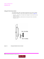
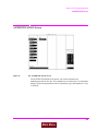
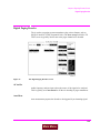
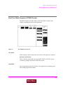
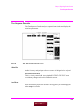
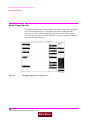
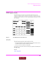
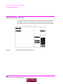
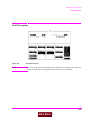
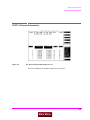
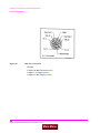
Figure 9 illustrates how to insert a memory card into the Test Set’s front panel. To
remove a memory card, simply pull it out.
The Test Set’s memory-card label is marked with an arrow that must be inserted
on the left side (when you are facing the Test Set) of the front-panel slot.
74
S:\agilent\8920\8920b\USRGUIDE\BOOK\CHAPTERS\opoverv.fb
Main Menu
Chapter 3, Operating Overview
Using Memory Cards
NOTE:
Figure 9
Memory cards may be inserted and removed with the Test Set powered on or off.
Inserting a Memory Card
75
Main Menu
Chapter 3, Operating Overview
Using Memory Cards
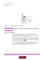
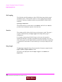
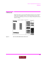
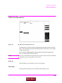
Setting the Write-Protect Switch
The SRAM memory card’s write-protect switch lets the user secure its contents
from being overwritten or erased. The switch has two positions (see Figure 10):
Figure 10
•
Read-write – The memory-card contents can be changed or erased, and new files may
written on the card.
•
Read-only – The memory-card contents can be read by the Test Set, but cannot be
changed or erased.
Setting the SRAM Write-Protect Switch
76
S:\agilent\8920\8920b\USRGUIDE\BOOK\CHAPTERS\opoverv.fb
Main Menu
Chapter 3, Operating Overview
Using Memory Cards
The Memory Card Battery
SRAM memory cards use a lithium battery to power the card. Listed below are the
batteries for the Test Set’s SRAM cards. SRAM cards typically retain data for
over 1 year at 25° C. To retain data, the battery should be replaced annually.
SRAM Card Battery Part Numbers - CR2025 or Agilent Technologies1420-0509
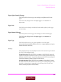
Replacing the Battery
1. Turn the Test Set on and insert the memory card. An inserted memory card takes power
from the Test Set, preventing the card’s contents from being lost.
2. Hold the memory card in the slot with one hand and pull the battery holder out with your
other hand. (See Figure 11 on page 78.)
NOTE:
The Test Set’s SRAM cards have a Battery Holder Lock switch immediately above the WriteProtect switch. If the switch is in the locked position the battery cannot be removed. Ensure
that the Battery Holder Lock switch is in the unlocked position before trying to remove the
battery.
3. Install the battery with the side marked “+” on the same side marked “+” on the battery
holder. Avoid touching the flat sides of the battery, finger oils may contaminate battery
contacts in the memory-card.
4. Re-insert the battery holder into the memory card.
NOTE:
The Test Set’s SRAM cards have a Battery Holder Lock switch immediately above the WriteProtect switch. Ensure that the Battery Holder Lock switch is in the locked position after
installing the new battery.
5. Remove the memory card from the Test Set.
77
Main Menu
Chapter 3, Operating Overview
Using Memory Cards
Figure 11
Replacing the Memory Card’s Battery
WARNING:
Do not mutilate, puncture, or dispose of batteries in fire. The batteries can burst or explode,
releasing hazardous chemicals. Discard unused batteries according to the manufacturer’s
instructions.
Memory Card Initialization
All new SRAM cards must be initialized before they can be used to store
information. The RAM_MANAGER procedure stored on the internal ROM Disk
can be used to quickly initialize any SRAM memory card.
SRAM Memory Cards can also be initialized from the TESTS screen by inserting
the memory card into the front-panel slot and selecting the Save/Delete field, then
selecting Init Card or pressing the k3 USER key to initialize a card. Follow the
on screen instructions to complete the process.
If the error message ERROR 85 Medium uninitialized appears on the screen
the memory card has not been properly initialized. Check the SRAM battery to
ensure that it’s charged and inserted correctly in the battery holder.
78
S:\agilent\8920\8920b\USRGUIDE\BOOK\CHAPTERS\opoverv.fb
Main Menu
Chapter 3, Operating Overview
Saving and Recalling Instrument Setups
Saving and Recalling Instrument Setups
The SAVE and RECALL functions allow you to store different instrument setups
and retrieve them later, eliminating the task of re-configuring the Test Set.
The number of available save registers depends on how many changes were made
to the base instrument setup for each save. (See “BASE Settings” on page 82.) The
smaller the number of changes, the greater the number of save registers that can
be used (typically over 200).
Save/Recall register settings can be saved to several types of mass storage. This
allows you to “back up the settings in case you need to clear them from memory
(see “Memory Considerations” on page 82) for running large programs, or when a
firmware upgrade is performed (see “Save/Recall” on page 449).
To Save an Instrument Setup
Use the More menu to access the I/O CONFIGURE screen. )
1. Select the storage media using the Save/Recall field. (The default is internal memory.
2. Make any changes to the instrument that you want to save in a register.
3. Press and release the SHIFT key then the RECALL key to access the SAVE function.
4. Use the DATA keys or the Save menu at the bottom right of the screen to enter the register’s name.
To Recall an Instrument Setup
Use the More menu to access the I/O CONFIGURE screen.
1. Select the media to recall settings from using the Save/Recall field. The default is
internal memory.
2. Press RECALL.
3. Use the knob to select the desired setup to be recalled from the Recall menu at the
bottom-right of the screen.
79
Main Menu
Chapter 3, Operating Overview
Saving and Recalling Instrument Setups
Example of Saving and Recalling an Instrument Setup
This example SAVES changes made to the RX TEST screen, and then RECALLS
them. The register is saved to wherever the Save/Recall field is set (internal
memory - unless you have changed it).
1. Access the RX TEST screen and set the RF Gen Freq to 500 MHz.
2. Set Amplitude to -35 dBm.
3. Press and release the SHIFT key then the RECALL key to access the SAVE function.
A prompt appears at the top of the screen asking you to enter a name.
4. Using the DATA keys, press 1 2 3 ENTER to assign a name to these changes.
5. Press PRESET and wait for the instrument to return to normal operation.
6. If not already displayed, access the RX TEST screen. Notice that the RF Gen Freq
and Amplitude settings are reset to their preset values.
7. Press RECALL 1 2 3 ENTER. The RF Gen Freq and Amplitude are changed to
the settings you saved in register 123 (500 MHz and -35 dBm).
To Remove (Clear) an Individual Save Register
Specify where the register is stored using the Save/Recall field on the I/O CONFIGURE screen.
1. Press RECALL.
2. Use the knob to position the cursor in front of the register to be removed from the Recall menu at the bottom-right of the screen. The register name and percentage of
memory occupied by that register are indicated at the top of the screen.
3. Press ON/OFF. A prompt appears, asking if you want to delete the save register.
4. Press YES.
80
S:\agilent\8920\8920b\USRGUIDE\BOOK\CHAPTERS\opoverv.fb
Main Menu
Chapter 3, Operating Overview
Saving and Recalling Instrument Setups
To Clear All Save Registers
1. Press RECALL.
2. Use the knob to position the cursor in front of the *Clr All* entry in the Recall
menu at the bottom-right of the screen.
3. Press the knob or press ENTER. A prompt appears at the top of the screen to verify that
you want to clear all registers.
4. Press YES.
Register Names
You can use any number, letter, or combination of numbers and letters as a name
for storing instrument settings. For instance; if you want to save a setup for testing
a “Vulcan7” radio, you can save the setting as “VULCAN7”.
Two register names are reserved for special purposes: POWERON and BASE.
POWERON Settings
When the Test Set is turned on, it uses a set of instrument setup parameters
specified at the time of manufacture. You can have the instrument power up in a
different state by making the desired changes to the original settings, and then
saving them using the name POWERON.
The next time the instrument is turned on, the instrument returns to the state
present when you saved the POWERON setting. For instance; if the
OSCILLOSCOPE screen was displayed when POWERON was saved, it is the
screen that is displayed when you turn the instrument on.
81
Main Menu
Chapter 3, Operating Overview
Saving and Recalling Instrument Setups
BASE Settings
The BASE register contains any field settings the user has saved that are different
from the instrument preset state. It establishes a reference point for all future
saves. If a base is not saved, the preset state is used as the reference.
When you save an instrument setup, the new setup is compared to the base
settings, and any differences are stored under the register name you supply.
Because only differences are stored, a much larger number of instrument setups
can be saved than if the contents of every field was saved.
When you recall an instrument setting, every field is reset to the base settings. The
saved settings are then used to re-establish the desired instrument setup.
CAUTION:
Since each save/recall register only contains the differences between the setup being saved and
the present base register settings, changing the base settings causes all other saved setups to be
erased from memory (including the POWERON setting if one has been saved).
Unless you consistently change the same fields to the same value each time you use the
instrument, you should avoid creating your own BASE settings.
Memory Considerations
When the Save/Recall field of the I/O CONFIGURE screen is set to
Internal, programs are saved to the same non-volatile RAM used to create
RAM Disk(s) and run IBASIC programs. By saving a large number of instrument
setups, you reduce the amount of RAM available to run programs. If you get a
“memory overflow” message while trying to load a program, you must clear one
or more save/recall registers to free RAM space.
Instrument Hardware Changes
Recalling a saved register that uses a hardware option that has been removed
(such as an audio filter) results in unspecified operation. Re-install the needed
option before attempting to recall the associated register(s).
82
S:\agilent\8920\8920b\USRGUIDE\BOOK\CHAPTERS\opoverv.fb
Main Menu
Chapter 3, Operating Overview
Using USER Keys
Using USER Keys
User keys instantly access instrument settings without using the knob. You can
use user keys to move quickly between fields on the same screen, and to access
field settings that are not normally available on the screen you are using.
Local user keys are used to move between settings on the screen that is displayed.
When the user key is pressed, the cursor instantly moves to, and selects, the
assigned field; eliminating the need to turn and push the knob. Five local user
keys are available for each screen: k1, k2, k3, k4, and k5.
Five factory-assigned local user keys are available in each screen; however, using
these keys removes any other local user keys you may have already set up.
Global user keys are used to access settings that are not available on the current
screen. Three global user keys are available: k1’, k2’, and k3’. (These are shifted
functions of the local user keys.)
When defining user keys, the ASSIGN function is used to create key definitions;
the RELEASE function removes the definitions. Re-assigning a user key to a
different field setting automatically releases it from the setting it was previously
associated with.
83
Main Menu
Chapter 3, Operating Overview
Using USER Keys
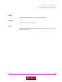
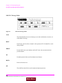
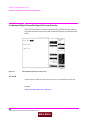
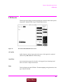
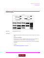
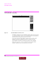
To Use the Pre-Assigned Local USER Keys
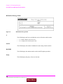
1. Press and release the SHIFT key, then the k4 key to access the ASSIGN function; then
press the ENTER key. The numbers 1 through 5 appear in front of various fields. (See
Figure 12.)
2. Press the different local user keys (k1 to k5) and notice how the cursor immediately
moves to the corresponding field.
3. To stop using the default local user keys, press and release the SHIFT key, then the k5
key to access the RELEASE function; then press the ENTER key.
scnusr.wmf
Figure 12
An Example of Pre-Assigned Local User Keys
84
S:\agilent\8920\8920b\USRGUIDE\BOOK\CHAPTERS\opoverv.fb
Main Menu
Chapter 3, Operating Overview
Using USER Keys
To Assign Local USER Keys
1. Move the cursor to the field you want to assign a local user key to.
2. Press and release the SHIFT key, then the k4 key to access the ASSIGN function. Then
press a local USER key (k1-k5). The user key number appears in front of the field you
assigned it to.
Example of Assigning a Local USER Key
Use this example to assign local USER key k1 to the Filter 1 field in the RX
TEST screen.
1. Access the RX TEST screen and position the cursor in front of the Filter 1 field.
2. Press and release the SHIFT key, then the k4 key to access the ASSIGN function; then
press k1. A small 1 appears next to the field indicating that USER key k1 has been assigned to it.
3. Move the cursor to any other field on the screen and press k1. The cursor immediately
returns to the Filter 1 field. The field is also highlighted to change the entry using
the CURSOR CONTROL knob or arrow keys.
To Release Local USER Keys
1. Display the screen containing the user key assignment to be removed.
2. Press and release the SHIFT key, then the k5 key to access the RELEASE function; then
press the USER key (k1-k5).
85
Main Menu
Chapter 3, Operating Overview
Using USER Keys
To Assign Global USER Keys
1. Move the cursor to the field you want to assign a global user key to.
2. Press and release the SHIFT key, then the k4 key to access the ASSIGN function. Then
press SHIFT and a global USER key (k1’ - k3’). Unlike a local user key, the user key
number does not appear at this field; instead, a prompt appears at the top of the screen
confirming the key assignment.
Example of Assigning a Global USER Key
Use this example to assign global USER key k1’ to the AF Anl In field, and then
access this field from the OSCILLOSCOPE screen.
1. Access the AF ANALYZER screen and position the cursor in front of the AF Anl In
field.
2. Press and release the SHIFT key, then the k4 key to access the ASSIGN function.
3. Press SHIFT, k1’. Notice the prompt Global User key 1 assigned. at the top
of the screen.
4. Access the OSCILLOSCOPE screen.
5. Press SHIFT, k1’.
AF Anl Input, FM Demod is displayed at the top of the screen (assuming the
present input is set to FM Demod). To change the input, use the arrow keys
(down-arrow or up-arrow), or press ENTER to access the Choices menu.
A field that is accessed using a global user key is only displayed at the top of the
screen while it is being accessed. Moving the cursor to any other field in the
screen causes the user key field to disappear until it is accessed again.
To Release Global USER Keys
1. Move the cursor to the field with the global user key assigned to it.
2. Press and release the SHIFT key, then the k5 key to access the RELEASE function.
Then press SHIFT and the USER key to be released (k1’-k3’).
86
S:\agilent\8920\8920b\USRGUIDE\BOOK\CHAPTERS\opoverv.fb
Main Menu
Chapter 3, Operating Overview
Setting an RF Generator/Analyzer Offset
Setting an RF Generator/Analyzer Offset
You can set a fixed frequency offset between the RF Generator and the
RF Analyzer. This feature is convenient for testing radios with a fixed
transmit/receive frequency offset.
To Set an RF Offset
1. Access the CONFIGURE screen.
2. Position the cursor in front of the RF Offset field, and press the Cursor Control knob,
or press ENTER to turn the offset On or Off.
3. Select the (Gen)-(Anl) field and enter the frequency offset value.
Example of Setting an RF Offset
1. Access the CONFIGURE screen.
2. Set the RF Offset to On.
3. Enter an offset frequency ((Gen)-(Anl)) of 10 MHz.
4. Access the DUPLEX screen.
5. Set the Tune Mode to Manual. 1
6. Select the RF Gen Freq field, and rotate the Cursor Control knob to vary the RF Generator’s frequency.
7. Notice that the Tune Freq value changes to maintain the 10 MHz difference between
the generator and the analyzer.
1. Manual tuning is used in this example to prevent possible unexpected Tune
Frequency changes during the procedure.
87
Main Menu
Chapter 3, Operating Overview
Using Remote Control
Using Remote Control
The Test Set can be remotely controlled several ways:
•
•
•
Using GPIB control from a computer/controller.
Using IBASIC programs on memory cards.
Using an ASCII terminal connected to the serial port.
Using GPIB Control
The Programmer’s Guide contains information on writing GPIB control programs
for the Test Set. Programming examples and a syntax listing provide general
GPIB operation guidelines.
Running IBASIC Programs from Memory Cards
The documentation shipped with Agilent Technologies11807 software packages
explains how to run those programs from memory cards. Refer to the
Programmer’s Guide for detailed information on using memory cards with your
own IBASIC programs.
88
S:\agilent\8920\8920b\USRGUIDE\BOOK\CHAPTERS\opoverv.fb
Main Menu
Chapter 3, Operating Overview
Using Remote Control
Using an ASCII Terminal
Connecting an ASCII terminal to the serial port allows you to remotely operate
the Test Set by entering characters that represent each front-panel control.
Before you can use this feature, you must first set the required serial port settings
in the I/O CONFIGURE screen, and make any hardware connections.
The Serial Port connections are described in Chapter 24, “Connector, Key, and
Knob Descriptions.”.
To Configure for Serial Port Operation
1. Access the I/O CONFIGURE screen.
2. Set the Serial In field to Inst.
3. Set the IBASIC Echo field to On.
4. Set the Inst Echo field to On.
5. Set the remaining serial communications fields according to your terminal/computer’s
serial communication requirements. These fields include:
• Serial Baud
• Parity
• Data Length
• Stop Length
• Rcv Pace
• Xmt Pace
6. The Test Set now responds to the equivalent characters sent to it by the terminal/computer.
Equivalent Front-Panel Control Characters
Table 7 on page 3 90 lists the terminal/computer keystrokes that equate to frontpanel controls. Each sequence must be preceded by the Escape key.
For example, to remotely access the CONFIGURE screen, press the Esc key, then
press the C key on your terminal/computer. Be sure to use upper-case C for this
example.
89
Main Menu
Chapter 3, Operating Overview
Using Remote Control
Table 7
Equivalent Front-Panel Control Characters
Equivalent ESC
Character
Function
CANCEL
!
Equivalent ESC
Character
Function
A
X
PERCENT MHZ_V
(
EEX
Z
S_KHZ_MV
)
YES_ON_OFF
[
BACKSPACE
-
NO_PPM_W
]
ENTER
.
RX
a
RELEASE
0
TX
b
K1
1
DUPLEX
c
K2
2
PREV
d
K3
3
TESTS_MAIN
e
K4
4
LOCAL
f
K5
5
RECALL
g
K1_PRIME
6
MEAS_RESET
h
K2_PRIME
7
PRESET
i
K3_PRIME
8
INCR_DIV_10
j
ASSIGN
9
INCR_SET
k
KNOB_TURN_CCW
<
INCR_TIMES_10
l
KNOB_TURN_CW
>
DOWN
m
MSSG
A
UP
n
HELP
B
SEVEN
o
CONFIG
C
EIGHT
p
HOLD
D
NINE
q
PRINT
E
FOUR
r
ADRS
F
FIVE
s
SAVE
G
SIX
t
REF_SET
J
ONE
u
METER
K
TWO
v
AVG
L
THREE
w
LO_LIMIT
M
ZERO
x
HI_LIMIT
N
POINT
y
E
R
PLUS_MINUS
z
F
S
OHM_PCT_DEL_DBUV
B
U
DB_GHZ_DBM
C
V
MS_HZ_UV
D
W
90
S:\agilent\8920\8920b\USRGUIDE\BOOK\CHAPTERS\opoverv.fb
Main Menu
|
Chapter 3, Operating Overview
Using Remote Control
Alternate sequences for 5 commonly-used functions are also available. Hold
down the Cntl (control) key and select the corresponding key for the desired
function. Example: Cntl H moves the cursor to the left one space.
ENTER - J or M
CANCEL - C
BACKSPACE - H
KNOB_TURN_CW - R
KNOB_TURN_CCW - L
91
Main Menu
Chapter 3, Operating Overview
Using Remote Control
92
S:\agilent\8920\8920b\USRGUIDE\BOOK\CHAPTERS\opoverv.fb
Main Menu
4
Adjacent Channel Power Screen
NOTE:
This screen is displayed on the Test Set with Option 102, Spectrum Analyzer.
This screen is used to measure Adjacent Channel Power. This is a measurement of
the power of signals at a specific channel spacing above and below the RF
Analyzer’s center frequency. This screen is accessed by selecting AD CH PWR
from the To Screen menu.
93
Main Menu
Chapter 4, Adjacent Channel Power Screen
How the Test Set Measures Adjacent Channel Power (ACP)
How the Test Set Measures Adjacent Channel Power (ACP)
When you access this screen, the Test Set automatically starts a multi-step process
for measuring ACP:
1. AF Generator 1 is turned off if the Carrier Ref field is set to Unmod.
2. The amplitude of the center frequency (Tune Freq) is measured to establish a
reference.
3. AF Generator 1 is turned back on if it was previously turned off.
4. The power in each of the adjacent channels is analyzed.
5. Adjacent Channel Power is calculated and displayed. This value can be displayed as an
absolute power level or as a ratio referenced to the center frequency’s level.
Which Input Port to Use. The TX Power measurement is used to calculate absolute
Adjacent Channel Power. Since TX Power can only be measured using the RF IN/OUT
port, you must use this port to measure ACP Level. ACP Ratio can be measured using
either the RF IN/OUT or the ANT IN port.
Measuring ACP on AM Transmitters. When measuring AM signals, the reference level
must be measured on an unmodulated carrier; so the Carrier Ref field must be set to
Unmod. After the reference is measured, the power in the adjacent channels must be measured with modulation. This requires the modulating signal to be turned off and on repeatedly as measurements are being calculated and displayed. Since the Test Set automatically
turns AFGen1 on and off when the Carrier Ref field is set to Unmod, you must use
AFGen1 and the AUDIO OUT port as the modulation source for making AM ACP measurements.
94
S:\agilent\8920\8920b\USRGUIDE\BOOK\CHAPTERS\acpscrn.fb
Main Menu
Chapter 4, Adjacent Channel Power Screen
Field Descriptions
Field Descriptions
adchpwr.wmf
Figure 13
The Adjacent Channel Power Screen
ACP Meas
This field selects the format for displaying upper and lower adjacent channel
power levels.
•
Ratio displays the power levels relative to the power around the center frequency
(Tune Freq). Levels can be displayed in dB or as a percentage (%).
•
Level displays the absolute power levels in mW, W, dBm, V, mV, and dBmV.
Operating Considerations
TX Power and ACP Level can only be measured through the RF IN/OUT port.
Four dashes are displayed for these measurements when the Input Port is set to
Ant (ANT IN).
ACP Ratio can be measured on either the ANT IN port or RF IN/OUT port.
For more information, refer to “How the Test Set Measures Adjacent Channel
Power (ACP)” on page 94.
95
Main Menu
Chapter 4, Adjacent Channel Power Screen
Field Descriptions
AFGen1 Freq
This field sets the frequency for the first audio frequency sinewave generator.
AFGen1 To
This field sets two values:
•
The upper field determines whether the AFGen1 signal modulates the RF Generator or
is output through the AUDIO OUT connector.
•
The lower field sets the depth of modulation for FM and AM in kilohertz and amplitude
(including Off) for audio out. The AUDIO OUT level is always in volts rms.
Operating Considerations
This is a priority control field. Accessing the RX TEST or TX TEST screen
overrides any changes made to this field in other screens.
See Also
“Interaction Between Screens” on page 56
Carrier Ref
Use the carrier reference field to indicate whether the carrier (Tune Freq) being
measured should be unmodulated or modulated when making the ACP reference
measurement. (For more information, refer to “How the Test Set Measures
Adjacent Channel Power (ACP)” on page 94.)
Operating Considerations
• FM transmitters can be measured with the carrier modulated or unmodulated.
• For AM transmitters, the carrier must be measured while unmodulated. AFGen1 and
the AUDIO OUT port must be used as the modulation source whenever Unmod is
selected.
Channel BW
Use the channel bandwidth field to specify the bandwidth of the carrier and
adjacent channels to be measured. (See Figure 14 on page 97.)
96
S:\agilent\8920\8920b\USRGUIDE\BOOK\CHAPTERS\acpscrn.fb
Main Menu
Chapter 4, Adjacent Channel Power Screen
Field Descriptions
adchpwr1.wmf
Figure 14
Relationship Between Tune Freq, Ch Offset, and Channel BW Fields
97
Main Menu
Chapter 4, Adjacent Channel Power Screen
Field Descriptions
Ch Offset
Use the channel offset field to enter the frequency difference between the Tune
Freq setting and the center of the adjacent channels you want to measure. This is
an absolute value; only positive values can be entered. See Figure 14 on page 97.
Ext TX key
This field controls a switch at the MIC/ACC connector. Use it to “key” an external
transmitter.
See Also
“MIC/ACC” on page 578
Input Atten
Input Attenuation sets the amount of input attenuation for the RF IN/OUT and
ANT IN connectors. This function controls two settings:
•
The upper field determines if you want the instrument to set the attenuation automatically (Auto), or if you want to set the value manually (Hold).
•
The lower field displays the present attenuation value, and is used to set the desired attenuation level when the upper area is set to Hold.
Operating Considerations
Input Attenuator autoranging can interfere with oscilloscope or signaling decoder
operation under certain conditions. See “Input Atten” on page 485 for additional
information.
98
S:\agilent\8920\8920b\USRGUIDE\BOOK\CHAPTERS\acpscrn.fb
Main Menu
Chapter 4, Adjacent Channel Power Screen
Field Descriptions
Input Port
This field selects the RF IN/OUT or ANT IN port for making RF measurements.
The RF IN/OUT port must be used for making TX Power or ACP Level
measurements on this screen.
Operating Considerations
Power levels for each port are printed on the Test Set’s front panel. If the RF
power at the RF IN/OUT port exceeds allowable limits, a loud warning signal
sounds and a message appears at the top of the screen. If this occurs, disconnect
the RF power, press the MEAS RESET key, and allow the Test Set to cool off for
approximately two minutes before making any other measurements on this port.
The ANT IN (antenna input) connector provides a highly-sensitive input for very
low level signals (such as “off the air” measurements). You cannot measure TX
(RF) Power or ACP Level on this screen using the ANT IN port.
CAUTION:
Connecting a signal of >200 mW to the ANT IN port can cause instrument damage
(although internal protection circuits can typically withstand a short-duration signal of 1 or
2 Watts).
If the overpower circuit is triggered (signified by a warning message at the top of
the screen), remove the signal from the ANT IN port, and press the MEAS
RESET key or turn the Test Set off and on to reset it.
Lower and Upper ACP [Ratio:Level]
These two measurements display the amount of power in signals above and below
the Tune Freq signal. The level is displayed as a ratio (referenced to the power
around the Tune Freq) or as an absolute value.
See Also
“ACP Meas” on page 95
99
Main Menu
Chapter 4, Adjacent Channel Power Screen
Field Descriptions
Res BW
The resolution bandwidth field selects the IF filter used when measuring the
power of the carrier and the adjacent channels.
Operating Considerations
Using a narrower bandwidth filter (300 Hz) slows the measurement, but rejects
carrier leakage and out of channel spurs. Using a wider bandwidth filter
(1 kHz) speeds measurements, but may allow unwanted spurs and carrier leakage
to be integrated into the measurement when measuring at the edges of the selected
channel bandwidth.
Tune Freq
This field sets the center frequency for the RF signal to be analyzed.
See Also
“Tune Mode” on page 100
Tune Mode
This field selects Automatic or Manual tuning of the RF Analyzer.
Auto tuning causes the RF Analyzer to find the signal with the greatest amplitude
>-36 dBm, and to set the Tune Frequency for that signal.
Manual tuning requires the operator to set the Tune Frequency for the RF signal
to be analyzed.
Operating Considerations
Changing the Tune Mode also changes the RF frequency display. Automatic
tuning enables the TX Frequency measurement. Manual tuning enables the
TX Freq Error measurement.
100
S:\agilent\8920\8920b\USRGUIDE\BOOK\CHAPTERS\acpscrn.fb
Main Menu
Chapter 4, Adjacent Channel Power Screen
Field Descriptions
TX Freq Error/TX Frequency
This measurement displays Transmitter Frequency Error or absolute Transmitter
Frequency.
See Also
“Tune Mode” on page 100
TX Power
Transmitter (TX) Power measures RF power at the RF IN/OUT port.
Operating Considerations
Only the RF IN/OUT port can be used for measuring TX Power on this screen.
When the Input Port is set to Ant, four dashes (- - - -) appear in place of digits
for this measurement.
Use the Spectrum Analyzer1 to measure low-level RF power (≤200 mW) at the
ANT IN port.
TX Pwr Meas
The transmitter power measurement field specifies how transmitter power
measurements are made:
•
•
Peak can be used to measure AM, FM, and un-modulated (CW) signals.
Sample can be used to measure FM or CW signals with increased measurement speed.
This method can only be used with signals having no amplitude modulation component.
Operating Considerations
If you change this field, zero the power measurement (using the TX Pwr Zero
field) before measuring power.
1.
Optional on some Test Set models.
101
Main Menu
Chapter 4, Adjacent Channel Power Screen
Field Descriptions
TX Pwr Zero
The transmitter power zero function establishes a 0.0000 W reference for
measuring RF power at the RF IN/OUT port.
CAUTION:
RF power must not be applied while zeroing. Set the RF Generator screen’s Amplitude
field to off to prevent internal cross-coupling into the power detector while zeroing.
Operating Considerations
When power is applied to the RF IN/OUT connector, the temperature of the
internal circuitry increases. This can cause changes in the TX Power measurement
when low power levels are measured immediately following high power
measurements.
When alternately making high and low power measurements, always zero the
power meter immediately before making the low power measurements; this
provides the best measurement accuracy.
102
S:\agilent\8920\8920b\USRGUIDE\BOOK\CHAPTERS\acpscrn.fb
Main Menu
5
AF Analyzer Screen
103
Main Menu
Chapter 5, AF Analyzer Screen
Block Diagram
Block Diagram
$)$QW,Q
)0'HPRG
,QSXW*DLQ
$)&QW*DWH
GE
)LOWHU
)0'HPRG
)URP,))LOWHUV
$0'HPRG
)LOWHU
N+]/3)
+]+3)
66%'HPRG
)URP$8',22XW
$XGLR2XW
)URP5DGLR,QWHUIDFH
&/.
$))UHT&RXQW
5DGLR,QW
5HDUSDQHO0RG,Q
([W0RG
)UHTXHQF\
)URP0,&$&&
0LF0RG
&RXQWHU
)URP$0)0
)00RG
0RGXODWRUV
$00RG
'LVSOD\
$XGLR,Q
)URP$8',2,Q+L
'H(PSKDVLV
'H(PS*DLQ
XV2I I
1RWFK*DLQ
G%
G%
)ORDW
$8',2,Q/R
*QG
3N0D[
N+]
7R+L
$8',2,Q/R
'HWHFWRU
506
6,1$'
'LVWRU WLRQ
*QG
506
5066457
'H(PS
3.
7R,QWHUQDO
9ROWPHWHU
3.
3.
)LOWHUV
3.0D[
3.+ROG
$&/HYHO
3.+ROG
3.+G
'&&XUUHQW
3N'HW7R
)LOWHUV
=HUR
)LOWHUV
,QSXW
)LOWHUV
&XUUHQW
7R,QWHUQDO
6HQVH
9ROWPHWHU
+
3.0[+G
6FRSH7R
1RWFK
$XGLR
'H(PS
0RQLWRU
)LOWHUV
2XWSXW
5HDU3DQHO
,QSXW
X6
'&0HDVXUHPHQW
7R2VFLOORVFRSH
7R'HFRGHU
7R,QWHUQDO
9ROWPHWHU
$/&
6SHDNHU
6SHDNHU$/&
2Q2))
92/80(
6SHDNHU9RO
3RW2II
Figure 15
AF ANALYZER Functional Block Diagram
1
The Settling, Gain Cntl, and Ext Load R fields are not shown.
Frequency Notch if purchased.
2Variable
104
S:\agilent\8920\8920b\USRGUIDE\BOOK\CHAPTERS\afascrn.fb
Main Menu
Chapter 5, AF Analyzer Screen
Block Diagram
Field Descriptions
AC Level
This measurement displays either rms potential (voltage) or audio power (Watts or
dBm).
Operating Considerations
When the unit-of-measure is changed to measure AF power, the external load
resistance must be specified. Refer to “Ext Load R” on page 110.
The input for the ac level measurement on this screen is always the AUDIO IN
connectors.
See Also
“Entering and Changing Numbers” on page 66
AF Anl In
The audio frequency analyzer input selects the input for the analyzer. When
selected, this field displays a list of choices.
Signals can be analyzed from three different types of inputs:
•
The output of the AM, FM, or SSB demodulators.
•
The AUDIO IN, RADIO INTERFACE, MODULATION INPUT, MIC/ACC, and
AUDIO OUT connectors.
•
The signal present at the AM or FM modulators for the RF Generator.
See Also
“Interaction Between Screens” on page 56
“Displaying Measurements” on page 60
105
Main Menu
Chapter 5, AF Analyzer Screen
Block Diagram
AF Cnt Gate
Audio frequency counter gate specifies how long the AF counter samples the
signal before displaying the frequency. Specifying a shorter gate time may enable
you to see frequency fluctuations that might not be seen using a longer gate time.
AF Freq
This is the default measurement for this measurement field. Selecting this field
displays the following measurement choices:
SINAD
Distortion
SNR (Signal to Noise Ratio)
AF Frequency
DC Level
Current - DC only Operating Considerations
This is a priority control field. Accessing the RX TEST or TX TEST screen
overrides any changes made to this field in other screens.
SNR Operation
• Selecting SNR turns off the other audio measurement.
• The RF Generator and AFGen1 must be set up to provide the radio’s carrier. AFGen1
is automatically turned on and off repeatedly during this measurement.
• AFGen2 must be turned off.
• The radio’s receiver’s audio output must be connected to the AUDIO IN port (set
the AF Anl In field to Audio In).
See Also
“Interaction Between Screens” on page 56
“Displaying Measurements” on page 60
106
S:\agilent\8920\8920b\USRGUIDE\BOOK\CHAPTERS\afascrn.fb
Main Menu
Chapter 5, AF Analyzer Screen
Block Diagram
AM Depth
This field displays the percent depth of modulation of the AM signal. The field is
only visible when the AF ANL In field is set to AM MOD or AM DEMOD
Audio In Lo
This field sets the AUDIO IN LO connector’s state.
•
Gnd causes the center pin of the connector to be connected directly to chassis ground.
•
Float isolates the center pin of the connector from ground, providing a floating input
to the AF Analyzer.
•
600 To Hi establishes a 600-ohm impedance between the center pins of the AUDIO
IN LO and AUDIO IN HI connectors. Also, the Ext Load R field is removed, since
the load is now fixed to 600 ohms.
Current
The Current field is found by selecting the SINAD field on the Test Set display
of the AF ANALYZER screen. This field only displays the DC current measured
at the DC input port on the back of the Test Set. Any offset can be removed by
selecting Zero from the DC Current field.
DC Current
DC current measurement zero removes any measurement offset present before
making a dc-current measurement. The measurement is zeroed by selecting Zero,
and pressing the ENTER key or the Cursor Control knob.
NOTE:
The current source must be disconnected before zeroing for accurate operation.
See Also
“DC CURRENT MEASUREMENT” on page 575
“SINAD, Distortion, SNR, AF Frequency, DC Level, DC Current” on page 63
Chapter 24, “Connector, Key, and Knob Descriptions,” on page 571
107
Main Menu
Chapter 5, AF Analyzer Screen
Block Diagram
DC Level
This field displays the DC voltage entering at the DC input port on the back of the
Test Set.
De-Emp Gain
De-emphasis gain displays and selects the desired AF analyzer de-emphasis
amplifier gain.
See Also
“Gain Cntl” on page 111
De-Emphasis
This setting selects or bypasses the 750 ms de-emphasis networks in the audio
analyzer and speaker circuitry.
See Also
“Interaction Between Screens” on page 56
Distn
This field displays the percent of distortion. The Distortion measurement is only
for a 1 kHz signaling tone.
108
S:\agilent\8920\8920b\USRGUIDE\BOOK\CHAPTERS\afascrn.fb
Main Menu
Chapter 5, AF Analyzer Screen
Block Diagram
Detector
This setting selects the type of detector used when measuring and displaying AF
signal levels.
Detector Types
• RMS displays the RMS value of signals.
•
displays the RMS value of a signal multiplied by 2 .
• Pk+ displays the positive peak value.
• Pk− displays the negative peak value.
• Pk±/2 adds the positive and negative peak values, and divides the sum by 2.
• Pk±Max compares the positive and negative peaks and displays the greater value
(polarity is not indicated).
• Pk+ Hold displays and holds the positive peak value until the measurement is reset.
To reset, press the MEAS RESET key, select a different detector, or re-select the same
detector.
• Pk− Hold displays and holds the negative peak value until the measurement is reset.
To reset, press the MEAS RESET key, select a different detector, or re-select the same
detector.
• Pk±/2 Hold divides the sum of the positive and negative peak values by 2, and
displays the value until the measurement is reset. To reset, press the MEAS RESET key,
select a different detector, or re-select the same detector.
• Pk±Mx Hold compares the positive and negative peaks and displays the greater value
until the measurement is reset. To reset, press the MEAS RESET key, select a different
detector, or re-select the same detector.
See Also
“Interaction Between Screens” on page 56
109
Main Menu
Chapter 5, AF Analyzer Screen
Block Diagram
Ext Load R
External Load Resistance is used to calculate and display AF power. Power is
calculated using the voltage measured at the AUDIO IN connections and the
resistance value you enter into this field.
Operating Considerations
This field is not displayed when the Audio In Lo field is set to 600 To Hi; the
load resistance is internally fixed to 600 ohms.
See Also
“AC Level” on page 105
“Audio In Lo” on page 107
Filter 1 and Filter 2
Filters 1 and 2 select a variety of standard and optional filters. Selecting either
field lists the choices available for that field.
FM Deviation
This is the default measurement for this field. The FM Deviation field displays the
frequency deviation between the FM signal and the carrier. The FM Deviation
measurement field is only displayed when the AF Anl In field is set to FM
Demod or FM Mod.
See Also
“AF Anl In” on page 105
“Displaying Measurements” on page 60
110
S:\agilent\8920\8920b\USRGUIDE\BOOK\CHAPTERS\afascrn.fb
Main Menu
Chapter 5, AF Analyzer Screen
Block Diagram
Gain Cntl
AF Analyzer Gain Control specifies whether the AF Analyzer’s gain settings are
controlled automatically by AF autoranging (Auto), or by manual control (Hold).
The following settings are affected by AF autoranging:
•
•
•
Input Gain
De-Emp Gain
Notch Gain
Operating Considerations
The normal mode of operation for the Gain Cntl field is Auto, allowing the
instrument to adjust the AF gain settings for optimum measurement accuracy.
This field can be set to Hold to disable the autoranging routines to increase
measurement speed. However, this requires you to select the desired gain settings
manually for each measurement.
NOTE:
Decoder and Oscilloscope Interference: The AF autoranging function (Auto)
takes a small amount of time to determine the attenuation settings for the AF
Analyzer. If you are decoding an encoded signal, and your transmitter begins sending
encoded information the instant it transmits, the initial encoded information may not
be decoded during the autoranging process.
Use the Auto setting to establish the initial gain settings while the encoded signal is
first being decoded, and then select Hold during the decoding process to retain the
gain settings. The decoder should capture all encoded information the next time you
transmit the signal.
Input Gain
This field displays and selects the gain of the AF Analyzer’s input amplifier. Refer
to the Gain Cntl field information.
111
Main Menu
Chapter 5, AF Analyzer Screen
Block Diagram
Notch Freq
This field sets the center frequency for the variable frequency notch filter. It is
typically used for distortion and SINAD measurements at frequencies below or
above the standard 1 kHz notch filter.
This field is not displayed if your Test Set does not have this feature.
Operating Considerations
When the Notch Coupl field on the CONFIGURE screen is set to AFGen1, this
filter and the AFGen1 Freq field match their settings. A warning message is then
displayed if you attempt to set the AFGen1 Freq value outside the 300 Hz to 10
kHz range of this filter. When the Notch Coupl field is set to None, this filter
and AFGen1 Freq operate independently.
Notch Gain
This field displays and selects the gain of the AF Analyzer’s notch filter amplifier.
This amplifier is only used for making SINAD and distortion measurements.
(Refer to the Gain Cntl field information.)
Pk Det To
Peak Detector To selects the signal source for the peak detectors. This allows you
to bypass certain sections of the AF analyzer’s circuitry when making ac-level
measurements.
See Also
Figure 15, “AF ANALYZER Functional Block Diagram,” on page 104.
112
S:\agilent\8920\8920b\USRGUIDE\BOOK\CHAPTERS\afascrn.fb
Main Menu
Chapter 5, AF Analyzer Screen
Block Diagram
Scope To
Oscilloscope To selects the signal source for the Oscilloscope. This allows you to
bypass certain sections of the AF analyzer’s circuitry when viewing and
measuring a signal. It also allows you to select measurement paths that include
additional gain stages, improving the oscilloscope’s resolution when measuring
low-level signals.
See Also
Figure 15, “AF ANALYZER Functional Block Diagram,” on page 104
Settling
This field selects the settling time for making AF measurements. Lower frequency
signals require additional settling time (Slow). Higher frequency measurements
require less settling time (Fast).
Operating Considerations
Use Slow for ≤200 Hz signals. Use Fast for >200 Hz signals.
If the signal being measured is a composite of different frequencies above and
below 200 Hz, select the appropriate filtering to analyze the desired signal
component.
113
Main Menu
Chapter 5, AF Analyzer Screen
Block Diagram
SINAD
This measurement field is used to select and display any one of the following
measurements:
SINAD
Distortion
SNR (Signal to Noise Ratio)
AF Frequency
DC Level
Current - DC only1 Operating Considerations
This is a priority control field. Accessing the RX TEST or TX TEST screen
overrides any changes made to this field in other screens.
SNR Operation
•
Selecting SNR turns off the other audio measurement.
•
The RF Generator and AFGen1 must be set up to provide the radio’s carrier. (AFGen1
is automatically turned on and off repeatedly during this measurement.)
•
AFGen2 must be turned off.
•
The radio’s receiver’s audio output must be connected to the AUDIO IN port (set the
AF Anl In field to Audio In).
See Also
“Interaction Between Screens” on page 56
SNR
The SNR field is found by selecting the SINAD field on the Test Set display of the
AF ANALYZER screen.This field displays the signal to noise ratio of the input
audio signal.
1.
Agilent 8920Brequires Current Measurement option
114
S:\agilent\8920\8920b\USRGUIDE\BOOK\CHAPTERS\afascrn.fb
Main Menu
Chapter 5, AF Analyzer Screen
Block Diagram
Speaker ALC
Speaker Automatic Level Control enables/disables the ALC function for the
instrument’s internal speaker. When On is selected, the speaker volume is
independent of the signal level being measured. When Off is selected, the speaker
volume is dependent on the signal level being measured.
Speaker Vol
Speaker Volume enables/disables the instrument’s internal speaker. When Pot is
selected, the VOLUME control knob operates normally. When Off is selected,
the speaker is disconnected.
TX Freq Error/ TX Frequency
This measurement area is used to display transmitter frequency error or
transmitter frequency. The type of measurement displayed depends on the Tune
Mode setting in the TX TEST, DUPLEX TEST, or RF ANALYZER screen.
See Also
“Displaying Measurements” on page 60
115
Main Menu
Chapter 5, AF Analyzer Screen
Block Diagram
TX Power
Transmitter Power measures RF power at the RF IN/OUT port.
Operating Considerations
Maximum signal levels at each port are printed on the front panel.
Only the RF IN/OUT port can be used for measuring TX Power on this screen.
When the Input Port is set to Ant, four dashes (- - - -) appear in place of digits
for this measurement.
Use the Spectrum Analyzer1 to measure low-level RF power (≤200 mW) at the
ANT IN port.
CAUTION:
Connecting a signal of >200 mW to the ANT IN port can cause instrument damage
(although internal protection circuits can typically withstand a short-duration signal of
1 or 2 Watts).
If the overpower circuit is triggered (signified by a warning message at the top of the
screen), remove the signal from the ANT IN port, and press the MEAS RESET key or
turn the Test Set off and on to reset it.
See Also
“Input Port” on page 486
“TX Power” on page 490
“TX Pwr Zero” on page 491
1.
Spectrum Analyzer is optional on some Test Set models.
116
S:\agilent\8920\8920b\USRGUIDE\BOOK\CHAPTERS\afascrn.fb
Main Menu
6
Call Processing Subsystem
117
Main Menu
Chapter 6, Call Processing Subsystem
Description of the Call Processing Subsystem
Description of the Call Processing Subsystem
The Call Processing Subsystem, which comprises six call processing screens,
allows the Test Set to simulate a cellular base station. The Call Processing
Subsystem provides, through host firmware control, the specific signals and
protocol messages necessary to automatically establish and maintain a cellular
link between the Test Set and a cellular phone (mobile station).
Once the link is established the operator can exercise the call processing functions
of the mobile station, such as
•
•
•
the decoding of orders from the base station, such as orders to retune the transceiver to
a new channel, to alert the mobile station user to an incoming call, to adjust the
transceiver output power level, or to release the mobile station upon completion of a
call.
the encoding of signaling information for transmission to the base station, such as
dialed digits for call origination, disconnect signal at the completion of a call, or mobile
identification number.
the authentication signaling associated with AMPS (IS-54) call processing such as
shared secret data update, unique challenge, origination with authentication, and page
with authentication.
In addition, when the link is established the Test Set performs the following
functions automatically:
•
•
measures some of the basic RF characteristics of the mobile station’s transmitted
carrier, such as; transmitter power, frequency accuracy, and modulation deviation
decodes and displays various reverse control channel and reverse voice channel
signaling messages
When sending forward control channel and forward voice channel messages, you
can set the bit pattern to an industry standard or to a pattern of your choice. The
ability to set the bit patterns gives the operator the opportunity to interject errors
into the signaling message, and test the mobile station’s ability to find these errors.
118
S:\agilent\8920\8920b\USRGUIDE\BOOK\CHAPTERS\callscrn.fb
Main Menu
Chapter 6, Call Processing Subsystem
Description of the Call Processing Subsystem
Operational Overview
The Test Set simulates a cellular base station by using its hardware and firmware
resources to initiate and maintain a link with a mobile station. Unlike a real base
station, the Test Set has only one transceiver (its signal generator and RF/AF
analyzer) and can support only one mobile station at a time. This means that the
Test Set’s transceiver can be configured as either a control channel or a voice
channel, but not both simultaneously.
To establish a link with a mobile station the Test Set’s transceiver is configured as
a control channel. Once a link has been established and the user wishes to test the
mobile station on a voice channel, the Test Set sends the appropriate information
to the mobile station on the control channel and then automatically re-configures
its transceiver to the voice channel assigned to the mobile station. Once the voice
channel link is terminated, the Test Set automatically re-configures its transceiver
back to being a control channel.
Handoffs are accomplished in a similar manner. When a handoff is initiated while
on a voice channel, the Test Set sends the necessary information to the mobile
station on the current voice channel. At the proper time, the Test Set automatically
re-configures its transceiver to the new voice channel.
Figure 16, “Call Processing State Diagram,” on page 120 illustrates the primary call
processing functions available in the Call Processing Subsystem. Each box
represents a call processing state and includes the measurement information
available while in that state. Each box also includes the name of the annunciator
on the call processing screen that will be lit while in that call processing state.
Events which trigger transitions between the various states are shown on the
diagram. Events which are initiated from the Test Set are shown in solid lines and
events which are initiated from the mobile station are shown in dashed lines.
119
Main Menu
Chapter 6, Call Processing Subsystem
Description of the Call Processing Subsystem
State: Idle
State: Register
Annunciator: None
Annunciator:
Meas: None
Active
Register
State: Active
Annunciator:
Register
Meas:RECCW A
RECCW B
RECCW C
Phone Number
ESN (hexadecimal)
SCM
Active
Meas: None
Page
SEND key pressed
while Roaming
or in Service mode
State: Page
Annunciator:
Page
Meas:RECCW A
RECCW B
RECCW C
State: Access
Annunciator:
State: Originate
Annunciator: None
Meas:RECCW A
RECCW B
RECCW C
RECCW D
RECCW E
Phone Number
ESN (hexadecimal)
SCM
Called number
Access
Meas: None
State: Connected
Annunciator: Connect
Release Meas:RVCOrdCon
TX Freq Error
TX Power
FM Deviation
RVCOrd
END key pressed
RVBSChal
while on an active
NRVC Ord
voice channel
Figure 16
Order
Handoff
Call Processing State Diagram
120
S:\agilent\8920\8920b\USRGUIDE\BOOK\CHAPTERS\callscrn.fb
Main Menu
= event initiated from Test Set
= event initiated from Mobile
Station
Chapter 6, Call Processing Subsystem
Description of the Call Processing Subsystem
Accessing the Call Processing Subsystem’s Screens
The Call Processing Subsystem screens are accessed by selecting CALL CNTL
from the To Screen menu on the Test Set’s CRT (you may have to choose the
More choice to display the CALL CNTL choice).
Call Processing Subsystem’s Screens
The Call Processing Subsystem consists of six screens.
NOTE:
•
The CALL CONTROL is the primary Call Processing Subsystem screen. This screen
contains the fields used to configure the Test Set’s parameters such as SAT Tone frequency, control channel number, and system identification number. Call processing
functions such as registration, page, and handoff can be activated from this screen. The
transmit power of the mobile station can be set from this screen. Data messages received from the mobile station are displayed on this screen.
•
The CALL DATA screen displays the decoded signaling messages received from the
mobile station on the reverse control channel and the reverse voice channel. Call processing functions such as registration, page, and handoff can also be activated from this
screen. The transmit power of the mobile station can be set from this screen.
•
The CALL BIT screen allows the advanced user to modify the contents of the forward
control channel and forward voice channel messages.
•
The CALL CONFIGURE screen contains the fields used to configure various parameters related to the Call Processing Subsystem, such as CMAX, Detector, and Input
Att.
•
The ANALOG MEAS screen is used to make analog RF and audio measurements on
the mobile station while a link is active.
•
AUTHENTICATION screen allows the user to turn on the AMPS authentication process (IS-54) during call processing functions. Various fields contained on this screen
allow the advanced user to select new RAND_A, RAND_B, RandSSD and RAND_U values for transmission to the mobile station. The user can also select the number of times
the system parameter overhead message is sent to the mobile station. AMPS Call Processing functions can be tested with or without authentication active.
Call Processing functions with Authentication are only supported for AMPS system types
(IS-54).
121
Main Menu
Chapter 6, Call Processing Subsystem
Using the Call Processing Subsystem
Using the Call Processing Subsystem
In order to use the Call Processing Subsystem, a mobile station must be powered
on, and connected to the Test Set.
Connecting A Mobile Station
Figure 17, “Connecting a Mobile Station to the Test Set,” on page 123 shows a
typical example of how to connect a mobile station to the Test Set. You may need
a special fixture to access the mobile station’s antenna, audio in, and audio out
signals. These fixtures are available from the mobile station’s manufacturer.
If any audio testing is to be done on the mobile station, the audio input
(microphone input) to the mobile station and the audio output (speaker output)
from the mobile station must be connected to the Test Set. If no audio testing is to
be done only the antenna needs to be connected to the Test Set.
122
S:\agilent\8920\8920b\USRGUIDE\BOOK\CHAPTERS\callscrn.fb
Main Menu
Chapter 6, Call Processing Subsystem
Using the Call Processing Subsystem
RF IN/OUT
AUDIO OUT
ANT IN
Microphone In
NOTE:
LO
Speaker Out
Antenna
Figure 17
AUDIO IN
HI
Mobile Station
Manufacturer’s
Special Fixture
Connecting a Mobile Station to the Test Set
Do not connect the antenna of the mobile station to the ANT IN port on the front panel of the
Test Set; this will cause the overpower protection circuitry to trip when the mobile station is
transmitting. Refer to “ANT IN” on page 572 for further information.
123
Main Menu
Chapter 6, Call Processing Subsystem
Using the Call Processing Subsystem
Mobile Station Audio Out Impedance
If the mobile station’s speaker is disconnected when using the manufacturer’s
special fixture, the user must ensure that the proper load impedance is applied to
the audio output of the mobile station. The special fixtures supplied by the
manufacturer of the mobile station may or may not terminate the audio output in
its proper load impedance. Refer to the manufacturer’s documentation for
information on the termination supplied by the special fixture.
If a load impedance must be supplied, then it can be placed across the AUDIO IN
connector. Refer to “AUDIO IN” on page 573 and Chapter 5, “AF Analyzer
Screen,” for further information.
600 Ohm Impedance
Some industry standards require the audio out of the mobile station to be
terminated in 600 ohms for testing purposes. The AUDIO IN connector of the Test
Set can be terminated in 600 ohms internally. Refer to “AUDIO IN” on page 573
and Chapter 5, “AF Analyzer Screen,” for further information.
124
S:\agilent\8920\8920b\USRGUIDE\BOOK\CHAPTERS\callscrn.fb
Main Menu
Chapter 6, Call Processing Subsystem
Using the Call Processing Subsystem
Generalized Procedures Using the Call Processing Subsystem
For general procedures for using the Call Processing Subsystem, see the following
sections:
•
•
•
•
•
•
•
•
•
•
•
•
•
•
“Conditioning the Test Set for Call Processing” on page 143
“Configure the Test Set” on page 144
“Turn On The Test Set’s Control Channel” on page 145
“Register a Mobile Station” on page 145
“Page a Mobile Station” on page 146
“Handoff a Mobile Station to a New Voice Channel” on page 148
“Release A Mobile Station” on page 148
“Change the Transmit Power Level of a Mobile Station” on page 149
“Originate a Call from a Mobile Station” on page 150
“Send an Alert Order to a Mobile Station” on page 151
“Changing the Content of a Message Field” on page 251
“Selecting The Message Content Generation Method” on page 248
“To Make an RF Sensitivity Measurement” on page 257
“To Make an FM Hum and Noise Measurement” on page 258
125
Main Menu
Chapter 6, Call Processing Subsystem
The CALL CONTROL Screen
The CALL CONTROL Screen
Figure 18
NOTE:
The CALL CONTROL Screen
The number of fields displayed on the CALL CONTROL screen depends on the selected
system type.
126
S:\agilent\8920\8920b\USRGUIDE\BOOK\CHAPTERS\callscrn.fb
Main Menu
Chapter 6, Call Processing Subsystem
The CALL CONTROL Screen
The CALL CONTROL screen is the primary Call Processing Subsystem screen. It
contains the most often used call processing configuration and command fields.
Figure 18 on page 126 shows the CALL CONTROL screen AMPS.
The top right-hand portion of the CALL CONTROL screen is used to display the
following information:
•
•
•
decoded data messages received from the mobile station on the reverse control channel
or the reverse voice channel
modulation quality measurements made on the mobile station’s RF carrier while on a
voice channel
raw data message bits, displayed in hexadecimal format, received from the mobile
station on the reverse control channel or reverse voice channel when a decoding error
occurs
The type of information to be displayed is selected using the Display field. Refer
to “Display” on page 131 for further information.
[] Access
When lit, the Access annunciator indicates the Test Set is signaling the mobile
station with command information on the forward voice channel. This is a
transitory state.
The Test Set’s speaker is turned off when in the access state. This is done to
eliminate any possible audio feedback which may occur if the mobile station’s
microphone is open.
Active
This field is used to turn on the forward control channel of the Test Set or to force
a return to the active state from any other state (register, page, access, connect). If
the forward control channel of the Test Set is already active, selecting this field
will deactivate and then reactivate the control channel.
127
Main Menu
Chapter 6, Call Processing Subsystem
The CALL CONTROL Screen
[] Active
When lit, the Active annunciator indicates the control channel of the Test Set is
turned on.
If this annunciator is lit, the base station is transmitting system parameter
overhead messages on the assigned control channel. If the annunciator is not lit,
the base station is not active.
NOTE:
The Test Set may still be outputting a modulated RF carrier but the Test Set’s firmware is not
active and no communication can occur between a mobile station and the Test Set.
AF Freq
The AF Freq field is displayed only when the Display field is set to Meas.
This field displays the audio frequency of the demodulated FM signal being
transmitted by the mobile station. Four dashes (----) indicate that no audio
frequency is present to measure. A numeric value would only be displayed when
the Test Set’s Connected annunciator is lit (connected state).
Amplitude
This field is used to set the output power of the Test Set’s transmitter (that is, the
output power of the Test Set’s RF Generator).
Called Number:
This field displays the called phone number, in decimal form, received from the
mobile station on the reverse control channel when the mobile station originates a
call. The Called Number: field is displayed only when the Display field is set
to Data and a reverse control channel message has been decoded when the mobile
originates a call.
128
S:\agilent\8920\8920b\USRGUIDE\BOOK\CHAPTERS\callscrn.fb
Main Menu
Chapter 6, Call Processing Subsystem
The CALL CONTROL Screen
CC Order
The CC Order field is only visible when authentication is activated on the
AUTHENTICATION screen.
This field is used to send an order on the forward control channel to the mobile
station. There are two orders available:
•
•
The SSD Update order ensures that the data contained in the mobile station and the base
station is identical. At the completion of the SSD Update process the mobile station and
the Test Set will contain identical copies of shared secret data.
The Unique Challenge order challenges the mobile station’s shared secret data through
a series of algorithm data output comparisons. A successful challenge confirms the
validity of a mobile station’s shared secret data.
Chan:
Chan: is divided into two fields:
•
•
The left-hand field displays the voice channel number assignment being used by the
Test Set and the mobile station. A numeric value would only be displayed when the Test
Set’s Connected annunciator is lit (connected state). A “-” is displayed if a mobile
station is not actively connected on a voice channel.
The right-hand field (highlighted field) is used to enter the voice channel number which
will be assigned to the mobile station by the Test Set as either an initial voice channel
assignment or as a handoff voice channel assignment.
Ch Loc:
This field is displayed only for the NAMPS system type.
CH Loc: is divided into two fields:
•
•
The left-hand field displays the current, narrow-analog-channel location assignment in
relation to the standard wide, analog channel. A range of U, M, L, or W is only displayed
when the Test Set’s Connected annunciator is lit (connected state). A “-” is displayed
if a mobile station is not actively connected on a voice channel.
The right-hand field (highlighted field) is used to enter the channel location range
which will be assigned to the mobile station by the Test Set as either an initial channellocation range assignment or as a handoff channel-location range assignment.
129
Main Menu
Chapter 6, Call Processing Subsystem
The CALL CONTROL Screen
Cntl Channel
This field is used to set the control channel number used by the Test Set.
The Cntl Channel field is an immediate action field. That is, whenever the
Cntl Channel field is changed, the change is reflected immediately in the
physical configuration of the Test Set (the control channel is immediately deactivated, reconfigured, and then re-activated to reflect the change) and causes an
immediate change to the current state of the Call Processing Subsystem (the state
is set to Active).
[] Connect
When lit, the Connect annunciator indicates that the mobile station is connected
to the Test Set on a voice channel.
NOTE:
When the CALL CONTROL screen is displayed and the Call Processing Subsystem is in
the connected state (Connect annunciator is lit), the Test Set constantly monitors the
mobile station’s transmitted carrier power. If the power falls below 0.0005 Watts the Test
Set will terminate the call and return to the active state (Active annunciator is lit). The
mobile station’s transmitted carrier power is monitored on all Call Processing Subsystem
screens except the ANALOG MEAS screen.
If the Test Set is in the connected state (Connect annunciator is lit) and a
change is made to the Cntl Channel field the connected state will be lost.
130
S:\agilent\8920\8920b\USRGUIDE\BOOK\CHAPTERS\callscrn.fb
Main Menu
Chapter 6, Call Processing Subsystem
The CALL CONTROL Screen
Display
This field is used to select the type of mobile station information to be displayed
in the upper right-hand portion of the CALL CONTROL screen:
•
•
Select Data to display information received from the mobile station on the reverse
control channel or reverse voice channel. If the data message(s) received from the
mobile station can be correctly decoded, the decoded message contents are displayed.
If the data messages cannot be correctly decoded, the raw data message bits are
displayed in hexadecimal format. Figure 19 on page 132 shows the layout of the CALL
CONTROL screen when a decoding error has occurred.
• The decoded order confirmation message, origination message, and order message
are available from the reverse control channel. The following pieces of information
are displayed when these messages are properly decoded: phone number, ESN
(dec), ESN (hex), the decoded Station Class Mark (SCM), and the called number.
The decoded SCM consists of: the mobile station power class (Class I, II, or III),
the transmission type (continuous/discontinuous), and the transmission bandwidth
(20 MHz or 25 MHz).
• The decoded Order Confirmation Message is available from the reverse voice
channel.
• For system type NAMPS, choose NData instead of Data.
Select Meas to display modulation quality measurements made on the mobile station’s
RF carrier while on a voice channel.
• For system types AMPS, TACS, JTACS, and wide channel NAMPS four
characteristics of the RF carrier are measured: TX Freq Error, TX Power, FM
Deviation, and AF Frequency. When set to the Meas display, the AF Analyzer’s
settings are 300 Hz HPF, 15 kHz LPF, De-Emphasis Off, PK+ detector. The Meas
information is available only when the Test Set’s Connect annunciator is lit
(connect state). Refer to the individual field descriptions for further information.
Figure 20 on page 132 shows the layout of the CALL CONTROL screen when
Meas is selected.
• For system type NAMPS with Ch Loc: set to Lower, Middle, or Upper, four
characteristics of the RF carrier are measured: TX Freq Error, TX Power, FM
Deviation, and DSAT/DST. When set to NMeas display, the AF Analyzer’s
settings are: 300 Hz HPF, 15 kHz LPF, De-Emphasis 750 µs, PK+ detector. The
NMeas information is available only when the Test Set’s Connect annunciator
is lit (connect state). Refer to the individual field descriptions for further
information. Figure 21 on page 133 shows the layout of the NAMPS CALL
CONTROL screen when NMeas is selected.
131
Main Menu
Chapter 6, Call Processing Subsystem
The CALL CONTROL Screen
Figure 19
CALL CONTROL Screen with Decoding Error Message Display
Figure 20
AMPS CALL CONTROL Screen with Meas Selected
132
S:\agilent\8920\8920b\USRGUIDE\BOOK\CHAPTERS\callscrn.fb
Main Menu
Chapter 6, Call Processing Subsystem
The CALL CONTROL Screen
Figure 21
NAMPS CALL CONTROL Screen with NMeas Selected
DSAT:
This field is displayed only when the system type is set to NAMPS.
DSAT: is divided into two field:
•
•
The left-hand field displays the DSAT control message identifier being broadcast by
the Test Set. The DSAT channel number identifier is displayed only when the Test Set’s
Connected annunciator is lit (connected state). A “-” is displayed if a mobile station
is not actively connected on a voice channel.
The right-hand field (highlighted field) is used to select one of the seven valid DSAT
sequences to be used on the voice channel (See “Chan:” on page 129 for more
information about the voice channel.) The DSAT channel number is followed by the
corresponding DSAT sequence as defined in IS-88.
133
Main Menu
Chapter 6, Call Processing Subsystem
The CALL CONTROL Screen
DSAT/DST (hex)
The DSAT/DST field is displayed only when the System Type field is set to
NAMPS and Display field is set to NMeas.
The DSAT/DST field displays the received DSAT/DST sequence from the mobile
station on the reverse voice channel. The received sequence is displayed in
hexadecimal form and can be checked against the DSAT value displayed in the
DSAT right-hand DSAT field. Four dashes (----) indicate no carrier is present to
measure. A hexadecimal value would only be displayed when the Test Set’s
Connected annunciator is lit (connected state).
ESN (dec):
This field displays the electronic serial number (ESN), in decimal form, received
from the mobile station on the reverse control channel in response to a forward
control channel message. The ESN (dec): field is displayed only when the
Display field is set to Data and a reverse control channel message containing
this information has been decoded.
ESN (hex):
This field displays the electronic serial number (ESN), in hexadecimal form,
received from the mobile station on the reverse control channel in response to a
forward control channel message. The ESN (hex): field is displayed only when
the Display field is set to Data and a reverse control channel message
containing this information has been decoded.
FM Deviation
This field displays the measured FM deviation of the RF carrier being transmitted
by the mobile station on the reverse voice channel. Four dashes (----) indicate no
carrier is present to measure. A numeric value would only be displayed when the
Test Set’s Connected annunciator is lit (connected state). The FM Deviation
field is only displayed when the Display field is set to Meas.
134
S:\agilent\8920\8920b\USRGUIDE\BOOK\CHAPTERS\callscrn.fb
Main Menu
Chapter 6, Call Processing Subsystem
The CALL CONTROL Screen
NOTE:
When the CALL CONTROL screen is displayed, the Test Set’s instrumentation is configured
for optimal performance of the signaling decoder. It is recommended that FM deviation
measurements be made using either the ANALOG MEAS screen. Using the CALL
CONTROL screen to make FM deviation measurements may result in slightly degraded
results.
Handoff
This field is used to initiate a handoff from the current voice channel assignments
to a new set of voice channel assignments. The voice channel number to hand the
mobile station off to, the channel location (NAMPS system type only), the initial
power level to use on the new voice channel, the DSAT sequence (NAMPS
system type only) to transpond on the mobile station, and the SAT tone frequency
to transpond on the new voice channel are specified using the Chan:, Ch Loc:,
Pwr Lvl:, DSAT:, and SAT: fields in the Voice Channel Assignment
section of the CALL CONTROL screen.
135
Main Menu
Chapter 6, Call Processing Subsystem
The CALL CONTROL Screen
MS Id
This field is used to enter the identification number of the mobile station. The
MS Id has two fields. The upper field is a one-of-many selection field and is used
to select the format for entering the identification number. The lower field is a
numeric entry field and is used to enter the identification number in the format
selected using the upper field. The contents of the lower field are automatically
updated upon successful completion of a mobile station registration.
There are two formats which can be used to enter the identification number. The
identification number can be entered as either the 10-digit phone number in
decimal (for example, 5095551212) or as the mobile identification number (MIN)
in hexadecimal (for example, AAABBBBBB). The first 3 characters (AAA) in the
field represent MIN2 and the last 6 characters (BBBBBB) represent MIN1.
To enter the identification number, select upper field and select the desired format
(Phone Num or MIN2 MIN1). Then select the lower field and enter the
information in the selected format. If the desired format is already selected then
simply select the lower field and enter the information in the selected format. The
formats are coupled, that is, if the Phone Num format is selected and the 10-digit
phone number is entered, the MIN2 MIN1 information is automatically updated,
and vice versa.
NOTE:
The preset values for the MS Id fields are:
• Phone Num = 1111111111
• MIN2 MIN1 = 000000400
An all zero MIN number (000000000), which does not represent a valid phone
number, will be converted to the following phone number: 111111?111.
136
S:\agilent\8920\8920b\USRGUIDE\BOOK\CHAPTERS\callscrn.fb
Main Menu
Chapter 6, Call Processing Subsystem
The CALL CONTROL Screen
Order
This field is used to send an order on the forward voice channel to the Mobile
Station. A mobile station must be actively connected on a voice channel to the
Test Set (that is, the Connect annunciator must be lit) before you can send an
order to a mobile station.
The Order field is a one-of-many selection field. To send an order to the mobile
station, select the Order field. A list of choices is displayed. Select the desired
order from the Choices: menu. The following orders are available:
•
•
•
•
Change Power to Power Level 0 - 7
Maintenance (put the mobile station in maintenance mode)
Alert (alert the mobile station)
MRI (mobile reported interference) request (NAMPS system type only)
Once the selection is made a mobile station control message is sent to the mobile
station. The Access annunciator will light momentarily while the Test Set is
sending the mobile station control message.
Pwr Lvl:
Pwr Lvl: is divided into two fields:
•
•
The left-hand field displays the mobile station’s output power level assigned to the
voice channel being used by the Test Set and the mobile station. A numeric value is
displayed only when a mobile station is actively connected on a voice channel (that is,
the Connect annunciator must be lit). A “-” is displayed if a mobile station is not
actively connected on a voice channel.
The right-hand field (highlighted field) is used to enter the Voice Mobile Attenuation
Code (VMAC). The VMAC determines the mobile station’s power level to be used on
the voice channel (See “Chan:” on page 129 for more information about the voice
channel).
Page
This field is used to initiate a page to the mobile station that is connected to the
Test Set. The Test Set must be in the active state (that is, Active annunciator
must be lit) and the MS Id information must be entered before you can attempt to
page the mobile station.
137
Main Menu
Chapter 6, Call Processing Subsystem
The CALL CONTROL Screen
[] Page
When lit, the Page annunciator indicates that the mobile station connected to the
Test Set is currently being paged on the forward control channel.
Phone Num:
This field displays the decoded MIN number received from the mobile station on
the reverse control channel in response to a forward control channel message. The
Phone Num: field is displayed only when the Display field is set to Data and a
reverse control channel message containing this information has been decoded.
CAUTION:
NOTE:
Do not confuse the Phone Num: field, which is displayed in the upper right-hand portion of
the CALL CONTROL screen, with the Phone Num selection of the MS Id field.
An all zero MIN number (000000000), which does not represent a valid phone number, will
convert to the following phone number: 111111?111.
Register
This field is used to initiate a registration of the mobile station that is connected to
the Test Set. The Test Set must be in the active state (that is, the Active
annunciator must be lit) before you can attempt to register the mobile station.
[] Register
When lit, the Register annunciator indicates that the mobile station connected
to the Test Set is being commanded to register with the Test Set.
Release
This field is used to terminate an active voice channel connection with the mobile
station. When the Release field is selected, a mobile station control message
with a release order is sent to the mobile station on the forward voice channel. A
mobile station must be actively connected on a voice channel to the Test Set (that
is, the Connect annunciator must be lit) before you can attempt to send a release
order to the mobile station.
138
S:\agilent\8920\8920b\USRGUIDE\BOOK\CHAPTERS\callscrn.fb
Main Menu
Chapter 6, Call Processing Subsystem
The CALL CONTROL Screen
SAT:
SAT: is divided into two fields:
he left-hand field displays the SAT frequency assigned to the voice channel being used by
the Test Set and the mobile station. A numeric value would only be displayed when the
Test Set’s Connected annunciator is lit (connected state). A “-” is displayed if a mobile
station is not actively connected on a voice channel.
The right-hand field (highlighted field) is used to set the SAT Color Code (SCC) to be
used on the designated voice channel (“Chan:” on page 129 for more information about
the voice channel).
SCM:
This field displays the decoded station class mark information received from the
mobile station on the reverse control channel in response to a forward control
channel message. The SCM: field is displayed only when the Display field is set
to Data and a reverse control channel message has been decoded.
SID
This field is used to set the system identification number (SID) of the Test Set.
The SID field is an immediate action field. If the field is selected and changed, the
signaling message(s) being sent on the forward control channel are immediately
changed. No change occurs to the current state (that is, active, register, page,
access, connect) of the Call Processing Subsystem.
139
Main Menu
Chapter 6, Call Processing Subsystem
The CALL CONTROL Screen
System Type
This field is used to select the type of cellular system (AMPS, NAMPS, TACS,
JTACS, DAMPS, DCCH) which will be simulated.
The System Type field is an immediate action field. That is, whenever the
System Type field is changed, the change is reflected immediately in the
physical configuration of the Test Set. The control channel is immediately deactivated, reconfigured, and then re-activated to reflect the change. This change
causes the Test Set to enter the active state).
NOTE:
If the Test Set is in the connected state (Connect annunciator is lit) and a change is made to
the System Type field, the connected state will be lost.
NOTE:
The Option 800, Agilent 83206A TDMA Cellular Adapter is required for system types DCCH
and DAMPS. Attempting to access these choices without Option 800 installed will generate
an “Option not installed.” error.
TX Freq Error
This field displays the frequency error (frequency error = assigned carrier
frequency - measured carrier frequency) of the RF carrier being transmitted by the
mobile station. Four dashes (----) indicate that no RF carrier is present to measure.
A numeric value would only be displayed in the connected state (that is, the
Connect annunciator is lit). The TX Freq Error field is displayed only when
the Display field is set to Meas.
TX Power
The TX Power field is displayed only when the Display field is set to Meas.
This field displays the measured RF power of the RF carrier being transmitted by
the mobile station. A non-zero value would only be displayed when the Test Set’s
Connect annunciator is lit).
When the CALL CONTROL screen is displayed and the Test Set is in the
connected state (Connect annunciator is lit), the mobile station’s transmitted
carrier power is constantly monitored. If the power falls below 0.0005 Watts, the
error message RF Power Loss indicates loss of Voice Channel will
be displayed, and the Test Set will terminate the call and return to the active state
(Active annunciator is lit).
140
S:\agilent\8920\8920b\USRGUIDE\BOOK\CHAPTERS\callscrn.fb
Main Menu
Chapter 6, Call Processing Subsystem
The CALL CONTROL Screen
NOTE:
In order to ensure that the Test Set makes the correct decisions regarding the presence of the
mobile stations’s RF carrier, the Test Set’s RF power meter should be zeroed before using the
Call Processing Subsystem. Failure to zero the power meter can result in erroneous RF power
measurements. See “Conditioning the Test Set for Call Processing” on page 143 for
information on manually zeroing the RF Power meter.
VC Order
This field is used to send an order on the forward voice channel to the Mobile
Station with authentication active. The VC Order field is only visible when
authentication is activated and the mobile is assigned a voice channel.
The orders available are:
•
•
•
•
•
Change Power to Power Level 0 - 7
Maintenance (put the mobile station in maintenance mode)
Alert (alert the mobile station)
SSD Update (shared secret data update)
Uniq Ch (unique challenge)
141
Main Menu
Chapter 6, Call Processing Subsystem
Using the CALL CONTROL Screen to Test Call Processing Functions
Using the CALL CONTROL Screen to Test Call Processing Functions
The CALL CONTROL screen provides multiple functions for testing a mobile
station. The following sections describe how to:
•
•
•
•
•
•
•
•
•
“Conditioning the Test Set for Call Processing” on page 143
“Configure the Test Set” on page 144
“Turn On The Test Set’s Control Channel” on page 145
“Register a Mobile Station” on page 145
“Page a Mobile Station” on page 146
“Handoff a Mobile Station to a New Voice Channel” on page 148
“Release A Mobile Station” on page 148
“Change the Transmit Power Level of a Mobile Station” on page 149
“Send an Alert Order to a Mobile Station” on page 151
142
S:\agilent\8920\8920b\USRGUIDE\BOOK\CHAPTERS\callscrn.fb
Main Menu
Chapter 6, Call Processing Subsystem
Using the CALL CONTROL Screen to Test Call Processing Functions
Conditioning the Test Set for Call Processing
Perform the following steps when first entering the Call Processing Subsystem
(that is, the first time the CALL CONTROL screen is selected during a
measurement session).
1. Zero the RF Power Meter.
a. Select the RF GEN from the To Screen menu.
b. Set the Amplitude field to off (use the ON/OFF key). This prevent cross-coupling into the power detector while zeroing the power meter.
c. Select CALL CNTL from the To Screen menu.
d. Select CALL CNFG from the To Screen menu.
e. Disconnect any cables from the RF IN/OUT port on the front panel of the Test Set.
f. Select the TX Pwr Zero field.
g. Select the RF Gen from the To Screen menu.
h. Set the Amplitude field to On.
There are two reasons for zeroing the RF power meter:
•
•
When any Call Processing Subsystem screen is displayed (except the ANALOG
MEAS screen) and the Call Processing Subsystem is in the connected state
(Connect annunciator is lit), the Test Set constantly monitors the mobile station’s
transmitted carrier power. If the power falls below 0.0005 Watts, the error message
RF Power Loss indicates loss of Voice Channel will be displayed
and the Test Set will terminate the call and return to the active state. Zeroing the
power meter cancels any inherent dc offsets that may be present within the power
meter under zero-power conditions. This ensures that the Test Set makes the correct
decisions regarding the presence of the mobile stations’s RF carrier.
Zeroing the power meter establishes a 0.0000 W reference for measuring the mobile
station’s RF power at the RF IN/OUT port. This ensures the most accurate RF
power measurements of the mobile station’s RF carrier at different power levels.
2. Couple the variable-frequency notch filter to AFGen1.
This step is only required if audio testing is to be done on the mobile station. This step
couples the variable-frequency notch filter to the output frequency of AFGen1 (audio
frequency generator1). The notch filter is used when making SINAD measurements.
AFGen1 is used to generate the audio tone for the SINAD measurement. Coupling the
notch filter to the audio source ensures the most accurate measurement.
a. Press and release the blue SHIFT key and then the DUPLEX key to display the
CONFIGURE screen.
b. Position the cursor on the Notch Coupl field and select AFGen1.
143
Main Menu
Chapter 6, Call Processing Subsystem
Using the CALL CONTROL Screen to Test Call Processing Functions
Configure the Test Set
1. Select CALL CNTL from the To Screen menu. The CALL CONTROL screen will
be displayed.
2. Verify that the Test Set configuration information is appropriate for the mobile station
to be tested. Check the following fields:
a. System Type - Select the type of cellular system to be simulated (AMPS,
NAMPS, TACS, JTACS, DAMPS, DCCH).
NOTE:
If the System Type field was modified in step2. b. the control channel will become active
since modifying this field automatically activates the control channel. Refer to “System
Type” on page 140.
b. Cntl Channel - Set the control channel number to be used by the Test Set.
NOTE:
If the Cntl Channel field was modified in step 2.b. the control channel will become active
since modifying this field automatically activates the control channel. Refer to “Cntl
Channel” on page 130.
c. Amplitude - Set the output power of the Test Set’s transmitter (that is, the output
power of the Test Set’s RF Generator).
d. SID - Enter the system identification number of the Test Set as a decimal number.
e. Chan: (right-hand field) - Enter the voice channel number which will be assigned
to the mobile station by the Test Set as either an initial voice channel assignment or
as a handoff voice channel assignment.
f. Ch Loc: (right-hand field, NAMPS system type only) - Select the narrow analog
channel location which will be assigned to the mobile station by the Test Set as either an initial channel location assignment or as a handoff channel location assignment. The choices are Lower (10 kHz below standard wide analog channels),
Middle (centered at the wide analog channel), Upper (10 kHz above the standard
analog channel) or Wide Chan.
g. Pwr Lvl: (right-hand field) - Enter the Voice Mobile Attenuation Code (VMAC).
The VMAC determines the mobile station power level to be used on the voice channel (See “Chan:” on page 129 for more information about voice channel).
h. DSAT: (right-hand field, NAMPS system type only) - Select the DSAT Color Code
(DSCC) to be used on the voice channel (See “Chan:” on page 129 for more information about voice channel)
i. SAT: (right-hand field) - Enter the SAT frequency to be used on the voice channel
(See “Chan:” on page 129 for more information about the voice channel).
3. Select CALL CNFG from the To Screen menu. The CALL CONFIGURATION
screen will be displayed.
4. Verify that the Test Set’s configuration information is appropriate for the mobile station
to be tested. Check the following fields:
a. CMAX - Set the number of access channels in the system. This will determine how
many channels must be scanned by the mobile station when trying to access the Test
Set. The value of this field will affect the time required for the mobile station to connect with the Test Set.
144
S:\agilent\8920\8920b\USRGUIDE\BOOK\CHAPTERS\callscrn.fb
Main Menu
Chapter 6, Call Processing Subsystem
Using the CALL CONTROL Screen to Test Call Processing Functions
Turn On The Test Set’s Control Channel
1. If not already done, condition the Test Set. See “Conditioning the Test Set for Call
Processing” on page 143 for further information.
1. If not already done, configure the Test Set. See “Configure the Test Set” on page 144
for further information.
2. If the CALL CONTROL screen is not displayed, select CALL CNTL from the To
Screen menu. The CALL CONTROL screen will be displayed.
3. Select the Active field. The Active annunciator will light when the control channel
is turned on.
Register a Mobile Station
1. Ensure that the Test Set is in the active state. See “Turn On The Test Set’s Control
Channel” on page 145 for information on how to activate the Test Set.
1. Connect the mobile station to the Test Set as shown in Figure 17, “Connecting a Mobile Station to the Test Set,” on page 123.
2. Turn on the mobile station.
3. If the CALL CONTROL screen is not displayed, select CALL CNTL from the To
Screen menu. The CALL CONTROL screen will be displayed.
4. Position the cursor on the Display field and select Data.
5. Select the Register field. The Register annunciator will light while the
registration is in process. If the mobile station responds properly on the reverse control
channel, the message RECC Return will flash momentarily in the upper right-hand
corner of the CALL CONTROL screen and the mobile station phone number, ESN and
decoded SCM will be displayed in the upper right-hand portion of the CALL
CONTROL screen. The information in the MS Id field will be updated. The Active
annunciator will light when the registration has successfully completed.
145
Main Menu
Chapter 6, Call Processing Subsystem
Using the CALL CONTROL Screen to Test Call Processing Functions
Page a Mobile Station
There are two methods that can be used to page a mobile station:
•
•
Page a mobile station that has registered with the Test Set.
Page a mobile station that has not registered with the Test Set.
Paging a Mobile Station that has Registered with the Test Set
1. Ensure that the Test Set is in the active state. See “Turn On The Test Set’s Control
Channel” on page 145 for information on how to activate the Test Set.
2. Connect the mobile station to the Test Set as shown in Figure 17, “Connecting a
Mobile Station to the Test Set,” on page 123.
3. Turn on the mobile station.
4. If the CALL CONTROL screen is not displayed, select CALL CNTL from the To
Screen menu. The CALL CONTROL screen will be displayed.
5. Position the cursor on the Display field and select Data.
6. Ensure that the mobile station has registered with the Test Set. See “Register a Mobile
Station” on page 145 for information on how to register the mobile station.
7. Select the Page field. The Page annunciator will light while the Test Set pages the
mobile on the forward control channel. If the mobile station responds properly on the
reverse control channel, the message RECC Return will flash momentarily in the
upper right-hand corner of the CALL CONTROL screen. The Access annunciator
will then light while the Test Set sends the mobile station an alert order on the assigned
voice channel. The mobile station should ring.
8. Press the SEND key on the mobile station. The Connect annunciator will light if the
mobile station properly signals the Test Set when the SEND key is pressed. The mobile
station is now connected to the Test Set on the assigned voice channel. The voice
channel assignment section will be updated: that is, any “-” in the left-hand fields will
be replaced with appropriate information.
146
S:\agilent\8920\8920b\USRGUIDE\BOOK\CHAPTERS\callscrn.fb
Main Menu
Chapter 6, Call Processing Subsystem
Using the CALL CONTROL Screen to Test Call Processing Functions
Paging a Mobile Station That Has Not Registered with the Test Set
1. Ensure that the Test Set is in the active state. See “Turn On The Test Set’s Control
Channel” on page 145 for information on how to activate the Test Set.
2. Connect the mobile station to the Test Set as shown in Figure 17, “Connecting a
Mobile Station to the Test Set,” on page 123.
3. Turn on the mobile station.
4. If the CALL CONTROL screen is not displayed, select CALL CNTL under the To
Screen menu. The CALL CONTROL screen will be displayed.
5. Position the cursor on the Display field and select Data.
6. Select the lower MS Id field. Enter the mobile station identification number, either the
phone number or the MIN number depending upon what the upper MS Id field is set to.
7. Select the Page field. The Page annunciator will light while the Test Set pages the
mobile on the forward control channel. If the mobile station responds properly on the
reverse control channel, the message RECC Return will flash momentarily in the
upper right-hand corner of the CALL CONTROL screen. The Access annunciator
will then light while the Test Set sends the mobile station an alert order on the assigned
voice channel. The mobile station should ring.
8. Press the SEND key on the mobile station. The Connect annunciator will light if the
mobile station properly signals the Test Set when the SEND key is pressed. The mobile
station is now connected to the Test Set on the assigned voice channel. The Voice
Channel Assignment fields will be updated: that is, any “-” in the left-hand fields
will be replaced with appropriate information.
147
Main Menu
Chapter 6, Call Processing Subsystem
Using the CALL CONTROL Screen to Test Call Processing Functions
Handoff a Mobile Station to a New Voice Channel
1. Ensure that the Test Set is in the connect state. See “Page a Mobile Station” on page
146 for information on how to bring a mobile station up on a voice channel.
2. If the CALL CONTROL screen is not displayed, select CALL CNTL from the To
Screen menu. The CALL CONTROL screen will be displayed.
3. Position the cursor on the Display field and select Data.
4. Select the Chan: field. Enter a new, valid voice channel number.
5. Select the Ch Loc: field (NAMPS system type only). Enter a new, valid channel
location from the Choices: menu.
6. Select the Pwr Lvl: field. Enter a new, valid mobile station power level.
7. Select the DSAT: field (NAMPS system type only). Enter a new, valid DSAT from the
Choices: menu.
8. Select the SAT: field. Enter a new, valid SAT frequency.
9. Select the Handoff field. The Access annunciator will light while the Test Set
signals the mobile station with the handoff information. If the mobile responds
properly, it will stop transmitting on the current voice channel, switch to the new voice
channel, and transpond the newly assigned SAT frequency. When the Test Set detects
this has happened the Connect annunciator is lit indicating that the handoff was
successful. The Voice Channel Assignment section will be updated; that is, any
“−” in the left-hand fields will be replaced with appropriate information.
Release A Mobile Station
1. Ensure that the Test Set is in the connected state. See “Page a Mobile Station” on page
146 for information on how to bring a mobile station up on a voice channel.
1. If the CALL CONTROL screen is not displayed, select CALL CNTL from the To
Screen menu. The CALL CONTROL screen will be displayed.
2. Select the Release field. The Test Set will signal the mobile station with a release
order. The mobile station will respond to the release order and cease transmission. The
Test Set will terminate transmission on the forward voice channel, and the Connect
annunciator will turn off. The Test Set will then reconfigure itself for transmission on
the forward control channel, begin to transmit system parameter overhead messages,
and the Active annunciator will light.
148
S:\agilent\8920\8920b\USRGUIDE\BOOK\CHAPTERS\callscrn.fb
Main Menu
Chapter 6, Call Processing Subsystem
Using the CALL CONTROL Screen to Test Call Processing Functions
Change the Transmit Power Level of a Mobile Station
1. Ensure that the Test Set is in the connected state. See “Page a Mobile Station” on page
146 for information on how to bring a mobile station up on a voice channel.
1. If the CALL CONTROL screen is not displayed, select CALL CNTL from the To
Screen menu. The CALL CONTROL screen will be displayed.
2. Position the cursor on the Display field and select Meas. The upper right-hand portion of the CALL CONTROL screen will display modulation quality measurements of
the mobile station’s RF carrier. The Test Set’s data functions, such as the average
(AVG) function, can be used with any of the measurements. Measurement units can
also be changed as desired.
3. Select the Order field and select it. A Choices: menu is displayed showing the various power levels which the mobile station can be set to. Select the desired power level
from the Choices: menu. The Test Set will then signal the mobile station with an order to set its power level. If the mobile responds properly, the measured value in the TX
Power field will change.
4. Position the cursor on the Display field and select Data.
5. Select the Order field. Select the desired power level from the Choices: menu. The
Access annunciator will light while the Test Set signals the mobile station with an order to set its power level. If the mobile responds properly, the message REVC Return
will flash momentarily in the upper right-hand corner of the CALL CONTROL screen
and then the decoded order confirmation message received from the mobile station will
be displayed. The left-hand Pwr Lvl: field will be updated with the new power level
information. The Connect annunciator will light when signaling is complete.
149
Main Menu
Chapter 6, Call Processing Subsystem
Using the CALL CONTROL Screen to Test Call Processing Functions
Originate a Call from a Mobile Station
1. Ensure that the Test Set is in the active state. See “Turn On The Test Set’s Control
Channel” on page 145 for information on how to activate the Test Set.
1. Connect the mobile station to the Test Set as shown in Figure 17, “Connecting a Mobile Station to the Test Set,” on page 123.
2. Turn on the mobile station.
3. If the CALL CONTROL screen is not displayed, select CALL CNTL from the To
Screen menu. The CALL CONTROL screen will be displayed.
4. Position the cursor on the Display field and select Data.
5. Dial the desired phone number on the mobile station and press the SEND key on the
mobile station’s handset. The mobile station signals the Test Set on the reverse control
channel with an origination message which includes the dialed phone number, the
mobile station’s MIN number and the mobile station’s ESN. If the mobile station
transmitted properly on the reverse control channel, the message RECC Return will
flash momentarily in the upper right-hand corner of the CALL CONTROL screen and
then the mobile station phone number, ESN, decoded SCM, and the called phone
number will be displayed. The Test Set will then reconfigure itself to the voice channel
assignments set up in the Voice Channel Assignment section of the CALL
CONTROL screen. The Access annunciator will then light while the Test Set signals
the mobile station on the assigned voice channel. The Connect annunciator will light
if the mobile station properly signals the Test Set on the reverse voice channel. The
mobile station is now connected to the Test Set on the assigned voice channel. The lefthand fields will be replaced with appropriate information.
150
S:\agilent\8920\8920b\USRGUIDE\BOOK\CHAPTERS\callscrn.fb
Main Menu
Chapter 6, Call Processing Subsystem
Using the CALL CONTROL Screen to Test Call Processing Functions
Send an Alert Order to a Mobile Station
1. Ensure that the Test Set is in the connected state. See “Page a Mobile Station” on page
146 for information on how to bring a mobile station up on a voice channel.
1. If the CALL CONTROL screen is not displayed, select CALL CNTL under the To
Screen menu. The CALL CONTROL screen will be displayed.
2. Select the Order field. A Choices: menu is displayed showing the various orders
which can be sent to the mobile station. Select the Mainten order from the list of
choices. The Test Set will then go into the Access state and signal the mobile station
with a maintenance order. If the mobile station is responding properly it will go into its
maintenance state as defined by the applicable cellular system standard. The left-hand
fields in the Voice Channel Assignment section will display a ‘-’ while the Test
Set is in the access state.
3. Select the Order field. A Choices: menu is displayed showing the various orders
which can be sent to the mobile station. Position the cursor next to the Alert order and
select it. The Test Set will then signal the mobile station with an alert order. If the
mobile station is responding properly it will alert (that is, it will ring). Press the SEND
key on the mobile station to respond to the alert order. The mobile station should exit
the maintenance state. The Test Set, upon detecting that the mobile station has exited
the maintenance state, will return to the Connect state and the left-hand subfields in
the Voice Channel Assignment section will be updated with the current voice
channel assignment information.
NOTE:
Applicable cellular system standards may specify a time-out period for the maintenance state.
If an Alert order is not received during this time-out period the mobile station may take some
action as defined by the standard. One such action might be to terminate the voice channel
connection. Refer to the applicable cellular system standard for specific information
151
Main Menu
Chapter 6, Call Processing Subsystem
Using the CALL CONTROL Screen to test AMPS Authentication
Using the CALL CONTROL Screen to test AMPS Authentication
The process of testing AMPS authentication (IS-54) through the Call Processing
Subsystem requires the user to synchronize the base station and mobile station.
This synchronization requires that the base station and the mobile station possess
two pieces of shared secret data (SSD) to confirm a valid call. The first piece is
the ESN of the mobile station and the second piece is the mobile station’s A-key.
The A-key is a secret 26-digit number stored in the mobile station’s semipermanent memory. The following sections describe how to:
•
•
•
•
•
•
•
•
Condition the Test Set for Call Processing with Authentication
Configure the Test Set for authentication
Turn On The Test Set’s Control Channel
Initialize Call Processing with Authentication
Page a Mobile Station with Authentication
Originate a Call with Authentication
Perform an SSD Update
Perform a Unique Challenge
152
S:\agilent\8920\8920b\USRGUIDE\BOOK\CHAPTERS\callscrn.fb
Main Menu
Chapter 6, Call Processing Subsystem
Using the CALL CONTROL Screen to test AMPS Authentication
Condition the Test Set for Call Processing
Perform the following steps when first entering the Call Processing Subsystem
(that is, the first time the CALL CONTROL screen is selected during a
measurement session).
1. Zero the RF Power Meter.
a. Select the RF Gen from the To Screen menu.
b. Set the Amplitude field to off (use the ON/OFF key) This prevents cross-coupling into the power detector while zeroing the power meter.
c. Select CALL CNTL from the To Screen menu.
d. Select CALL CNFG from the To Screen menu.
e. Disconnect any cables from the RF IN/OUT port on the front panel of the Test Set.
f. Select the TX Pwr Zero field.
There are two reasons for zeroing the RF power meter:
•
•
When any Call Processing Subsystem screen is displayed (except the ANALOG
MEAS screen) and the Call Processing Subsystem is in the connected state
(Connect annunciator is lit), the Test Set constantly monitors the mobile station’s
transmitted carrier power. If the power falls below 0.0005 Watts, the error message
RF Power Loss indicates loss of Voice Channel will be displayed
and the Test Set will terminate the call and return to the active state. Zeroing the
power meter cancels any inherent dc offsets that may be present within the power
meter under zero-power conditions. This ensures that the Test Set makes the correct
decisions regarding the presence of the mobile stations’s RF carrier.
Zeroing the power meter establishes a 0.0000 W reference for measuring the mobile
station’s RF power at the RF IN/OUT port. This ensures the most accurate RF
power measurements of the mobile station’s RF carrier at different power levels.
2. Couple the variable-frequency notch filter to AFGen1.
This step is only required if audio testing is to be done on the mobile station. This step
couples the variable-frequency notch filter to the output frequency of AFGen1 (audio
frequency generator 1). The notch filter is used when making SINAD measurements.
AFGen1 is used to generate the audio tone for the SINAD measurement. Coupling the
notch filter to the audio source ensures the most accurate measurement.
a. Press and release the blue SHIFT key and then the DUPLEX key to display the
CONFIGURE screen.
b. Position the cursor on the Notch Coupl field and select AFGen1.
153
Main Menu
Chapter 6, Call Processing Subsystem
Using the CALL CONTROL Screen to test AMPS Authentication
Configure the Test Set
1. Select CALL CNTL from the To Screen menu. The CALL CONTROL screen will
be displayed.
2. Verify that the Test Set configuration information is appropriate for the mobile station
to be tested. Check the following fields:
a. System Type - Select AMPS. At this time, only AMPS is supported for authentication.
NOTE:
If the System Type field was modified in step 2a- the control channel will become active
since modifying this field automatically activates the control channel. Refer to the “System
Type” on page 140.
b. Cntl Channel - Set the control channel number to be used by the Test Set.
NOTE:
If the Cntl Channel field was modified in step 2b the control channel will become active
since modifying this field automatically activates the control channel. Refer to “Cntl
Channel” on page 130.
c. Amplitude - Set the output power of the Test Sets’s transmitter (that is, the output
power of the Test Set’s RF Generator).
d. SID - Enter the system identification number of the Test Set as a decimal number.
e. Chan: (right-hand field) - Enter the voice channel number which will be assigned
to the mobile station by the Test Set as either an initial voice channel assignment or
as a handoff voice channel assignment.
f. Pwr Lvl: (right-hand field) - Enter the Voice Mobile Attenuation Code (VMAC).
The VMAC determines the mobile station power level to be used on the voice channel (See “Chan:” on page 129 for more information about the voice channel).
g. SAT: (right-hand field) - Enter the SAT frequency to be used on the designated
voice-channel (See “Chan:” on page 129 for more information about the voice
channel).
3. Select CALL CNFG under the To Screen menu. The CALL CONFIGURATION
screen will be displayed.
4. Verify that the Test Set’s configuration information is appropriate for the mobile station
to be tested. Check the following field:
a. CMAX - Set the number of access channels in the system. This will determine how
many channels must be scanned by the mobile station when trying to access the Test
Set. The value of this field will affect the time required for the mobile station to connect with the Test Set.
154
S:\agilent\8920\8920b\USRGUIDE\BOOK\CHAPTERS\callscrn.fb
Main Menu
Chapter 6, Call Processing Subsystem
Using the CALL CONTROL Screen to test AMPS Authentication
Turn on the Test Set’s Control Channel
1. If not already done, condition the Test Set. See “Condition the Test Set for Call Processing” on page 153 for further information.
2. If not already done, configure the Test Set. See “Configure the Test Set” on page 154
for further information.
3. If the CALL CONTROL screen is not displayed, select CALL CNTL from the To
Screen menu. The CALL CONTROL screen will be displayed.
4. Select Active field. The Active annunciator will light when the control channel is
turned on.
Initialize Call Processing with Authentication
There are two methods to initialize Call Processing with authentication.
•
•
Initializing Call Processing with Authentication through registration with the Test Set.
Initializing Call Processing with Authentication without registration with the Test Set.
Initialize Call Processing through Registration
1. Ensure that the Test Set is in the active state. See “Turn on the Test Set’s Control
Channel” on page 155 for information on how to activate the Test Set.
2. Connect the mobile station to the Test Set as shown in Figure 17, “Connecting a
Mobile Station to the Test Set,” on page 123.
3. Turn on the mobile station.
4. If the CALL CONTROL screen is not displayed, select CALL CNTL under the To
Screen menu. The CALL CONTROL screen will be displayed.
5. Position the cursor on the Display field and select Data.
6. Select the Register field. The Register annunciator will light while the
registration is in process. If the mobile station responds properly on the reverse control
channel, the message RECC Return will flash momentarily in the upper right-hand
corner of the CALL CONTROL screen and then the mobile station’s phone number,
ESN and decoded SCM will be displayed in the upper right-hand portion of the CALL
CONTROL screen. The information in the MS Id field will be updated. The Active
annunciator will light when the registration has successfully completed.
7. Select AUTHEN on the To Screen field. The AUTHENTICATION screen will be
displayed.
8. Select the A_KEY field and enter a valid A_KEY in decimal format.
9. Position the cursor on the Off/On field and select On.
10. Select CALL CNTL from the To Screen menu. The CALL CONTROL screen will
be displayed.
155
Main Menu
Chapter 6, Call Processing Subsystem
Using the CALL CONTROL Screen to test AMPS Authentication
11. Select SSD Upd in the CC Order field. The Access annunciator light will light while
the SSD Update order is in progress. If the mobile station responds properly on the
reverse control-channel, “SSD Update Order Successful” will be displayed
in the upper right-hand portion of the CALL CONTROL screen. The test set and the
mobile station now share common secret data and further call processing functions with
authentication can be tested. If the order failed, then “SSD Update Order
Failed” will appear on the upper right-hand portion of the CALL CONTROL screen.
Initializing Authentication without Registration
1. Ensure that the Test Set is in the active state. See “Turn on the Test Set’s Control
Channel” on page 155 for information on how to activate the Test Set.
2. Connect the mobile station to the Test Set as shown in Figure 17, “Connecting a
Mobile Station to the Test Set,” on page 123.
3. Turn on the mobile station.
4. If the CALL CONTROL screen is not displayed, select CALL CNTL from the To
Screen menu. The CALL CONTROL screen will be displayed.
5. Position the cursor on the Display field and select Data.
6. Select the upper MS ID field and then select MIN2 MIN1 from the Choices: menu.
7. Select the lower MS ID field and enter the information in hexadecimal format.
8. Select AUTHEN from the To Screen menu. The AUTHENTICATION screen will be
displayed.
9. Select the A_KEY field and enter a valid A_KEY in decimal format.
10. Select the ESN field and enter the mobile station’s electronic serial number in a
hexadecimal format.
11. Position the cursor on the Off/On field and select On.
12. Select CALL CNTL from the To Screen menu. The CALL CONTROL screen will
be displayed.
13. Select SSD Upd from the CC Order field. The Access annunciator light will light
while the SSD Update order is in progress. If the mobile station responds properly on
the reverse control-channel, “SSD Update Order Successful” will be
displayed in the upper right-hand portion of the CALL CONTROL screen. The test set
and the mobile station now share common secret data and further call processing
functions with authentication can be tested. If the order failed, then “SSD Update
Order Failed” will appear on the upper right-hand portion of the CALL
CONTROL screen.
156
S:\agilent\8920\8920b\USRGUIDE\BOOK\CHAPTERS\callscrn.fb
Main Menu
Chapter 6, Call Processing Subsystem
Using the CALL CONTROL Screen to test AMPS Authentication
Page a Mobile Station with Authentication
Paging A Mobile Station That Has Registered With The Test Set
1. Ensure that the Test Set is in the active state. See “Turn on the Test Set’s Control
Channel” on page 155 for information on how to activate the Test Set.
2. Connect the mobile station to the Test Set as shown in Figure 17, “Connecting a
Mobile Station to the Test Set,” on page 123.
3. Turn on the mobile station.
4. If the CALL CONTROL screen is not displayed, select CALL CNTL from the To
Screen menu. The CALL CONTROL screen will be displayed.
5. Position the cursor on the Display field and select Data.
6. Ensure that the mobile station has registered with the Test Set. See “Initialize Call
Processing with Authentication” on page 155 for information on how to register the
mobile station.
7. Select the Page field. The Page annunciator will light while the Test Set pages the
mobile on the forward control channel. If the mobile station responds properly on the
reverse control-channel the message RECC Return will flash momentarily in the
upper right-hand corner of the CALL CONTROL screen. The Access annunciator
will then light while the Test Set sends the mobile station an alert order on the assigned
voice channel. The mobile station should ring.
8. Press the SEND key on the mobile station. The Connect annunciator will light if the
mobile station properly signals the Test Set. The mobile station is now connected to the
Test Set on the assigned voice channel. The Voice Channel Assignment fields
will be updated, that is, any “-” in the left-hand fields will be replaced with appropriate
information. If page with authentication was successful, “Page w/Auth
successful” will be displayed in the upper right-hand portion of the CALL
CONTROL screen. If page with authentication failed, then “Page w/Auth
failed” will be displayed in the upper right-hand portion of the CAll CONTROL
Screen.
157
Main Menu
Chapter 6, Call Processing Subsystem
Using the CALL CONTROL Screen to test AMPS Authentication
Originate a Call with Authentication
1. Ensure that the Test Set is in the active state. See “Turn On The Test Set’s Control
Channel” on page 145 for information on how to activate the Test Set.
2. Connect the mobile station to the Test Set as shown in Figure 17, “Connecting a
Mobile Station to the Test Set,” on page 123.
3. Turn on the mobile station.
4. If the CALL CONTROL screen is not displayed, select CALL CNTL under the To
Screen menu. The CALL CONTROL screen will be displayed.
5. Position the cursor on the Display field and select Data.
6. Ensure that the mobile station has registered with the Test Set. See “Initialize Call
Processing with Authentication” on page 155 for information on how to register the
mobile station.
7. Dial the desired phone number on the mobile station and press the SEND key on the
mobile station’s handset. The mobile station signals the Test Set on the reverse control
channel with an origination message which includes the dialed phone number, the
mobile station’s MIN number and the mobile station’s ESN. If the mobile station
transmitted properly on the reverse control channel, the message RECC Return will
flash momentarily in the upper right-hand corner of the CALL CONTROL screen and
then the mobile station’s phone number, ESN, decoded SCM, and called phone number
will be displayed. The Test Set will then reconfigure itself to the voice channel
assignments set up in the Voice Channel Assignment section of the CALL
CONTROL screen. The Access annunciator will then light while the Test Set signals
the mobile station on the assigned voice channel. The Connect annunciator will light
if the mobile station properly signals the Test Set on the reverse voice channel. The
mobile station is now connected to the Test Set on the assigned voice channel. The
Voice Channel Assignment fields will be replace with appropriate information.
If origination with authentication was successful, then “Origination w/Auth
successful” will be displayed in the upper right-hand portion of the CALL
CONTROL screen. If origination with authentication failed, then “Origination w/
Auth failed” will be displayed in the upper right-hand portion of the CAll
CONTROL Screen.
158
S:\agilent\8920\8920b\USRGUIDE\BOOK\CHAPTERS\callscrn.fb
Main Menu
Chapter 6, Call Processing Subsystem
Using the CALL CONTROL Screen to test AMPS Authentication
Perform an SSD Update
There are two methods that can be used to perform an SSD Update:
•
•
SSD Update on the Control Channel
SSD Update on the Voice Channel
Performing an SSD Update on the Control Channel
1. Ensure that the Test Set is in the active state. See “Turn on the Test Set’s Control
Channel” on page 155 for information on how to activate the Test Set.
2. Connect the mobile station to the Test Set as shown in Figure 17, “Connecting a
Mobile Station to the Test Set,” on page 123.
3. Turn on the mobile station.
4. If the CALL CONTROL screen is not displayed, select CALL CNTL from the To
Screen menu. The CALL CONTROL screen will be displayed.
5. Position the cursor on the Display field and select Date.
6. Ensure that the Test Set has Initialized Call Processing with Authentication. See
“Initialize Call Processing with Authentication” on page 155 for information on
how to register the mobile station and activate Authentication.
7. Select AUTHEN on the To Screen meun.The AUTHENTICATION screen will be
displayed.
8. Select RANDSSD_1 field. Enter a new, valid RANDSSD_1 value (6-digit
hexadecimal).
9. Select RANDSSD_2 field. Enter a new, valid RANDSSD_2 value (6-digit
hexadecimal).
10. Select RANDSSD_3 field. Enter a new, valid RANDSSD_3 value (2-digit
hexadecimal).
11. Select CALL CNTL under the To Screen menu. The CALL CONTROL screen will
be displayed.
12. Select SSD Upd on the CC Order field. The Access annunciator light will light
while the SSD Update order is in progress. If the mobile station responds properly on
the reverse control channel, “SSD Update Order Successful” will be
displayed in the upper right-hand portion of the CALL CONTROL screen. The Test Set
and the mobile station are now linked and further call processing functions with
authentication can be tested. If the order failed, then “SSD Update Order
Failed” will appear on the upper right-hand portion of the CALL CONTROL screen.
159
Main Menu
Chapter 6, Call Processing Subsystem
Using the CALL CONTROL Screen to test AMPS Authentication
Performing an SSD Update on the Voice Channel
1. Ensure that the Test Set is in the active state. See “Turn on the Test Set’s Control
Channel” on page 155 for information on how to activate the Test Set.
2. Connect the mobile station to the Test Set as shown in Figure 17, “Connecting a
Mobile Station to the Test Set,” on page 123.
3. Turn on the mobile station.
4. If the CALL CONTROL screen is not displayed, select CALL CNTL from the To
Screen menu. The CALL CONTROL screen will be displayed.
5. Position the cursor on the Display field and select Data.
6. Ensure that the Test Set has Initialized Call Processing with Authentication. See
“Initialize Call Processing with Authentication” on page 155 for information on
how to register the mobile station and activate Authentication.
7. Ensure that the mobile station is on a voice channel. See “Page a Mobile Station with
Authentication” on page 157 .
8. Select AUTHEN from the To Screen menu. The AUTHENTICATION screen will be
displayed.
9. Select the RANDSSD_1 field. Enter a new, valid RANDSSD_1 value (6-digit
hexadecimal).
10. Select the RANDSSD_2 field. Enter a new, valid RANDSSD_2 value (6-digit
hexadecimal).
11. Select the RANDSSD_3 field. Enter a new, valid RANDSSD_3 value (2-digit
hexadecimal).
12. Select CALL CNTL under the To Screen menu. The CALL CONTROL screen will
be displayed.
13. Select SSD Upd on the VC Order field. The Access annunciator light will light
while the SSD Update order is in progress. If the mobile station responds properly on
the reverse control channel, “SSD Update Order Successful” will be
displayed in the upper right-hand portion of the CALL CONTROL screen. If the order
failed then “SSD Update Order Failed” will appear on the upper right-hand
portion of the CALL CONTROL screen.
160
S:\agilent\8920\8920b\USRGUIDE\BOOK\CHAPTERS\callscrn.fb
Main Menu
Chapter 6, Call Processing Subsystem
Using the CALL CONTROL Screen to test AMPS Authentication
Perform a Unique Challenge
There are two methods that can be used to perform a Unique Challenge-Response
procedure:
•
•
Unique Challenge on the Control Channel
Unique Challenge on the Voice Channel
Performing a Unique Challenge on the Control Channel
1. Ensure that the Test Set is in the active state. See “Turn on the Test Set’s Control
Channel” on page 155 for information on how to activate the Test Set.
2. Connect the mobile station to the Test Set as shown in Figure 17, “Connecting a
Mobile Station to the Test Set,” on page 123.
3. Turn on the mobile station.
4. If the CALL CONTROL screen is not displayed, select CALL CNTL under the To
Screen menu. The CALL CONTROL screen will be displayed.
5. Position the cursor on the Display field and select Data.
6. Ensure that the Test Set has Initialized Call Processing with Authentication. See
“Initialize Call Processing with Authentication” on page 155 for information on
how to register the mobile station and activate Authentication.
7. Select AUTHEN on the To Screen menu. The AUTENTICATION will be displayed.
8. Select RAND_U field. Enter a new, valid RAND_U value (6-digit hexadecimal).
9. Select CALL CNTL under the To Screen menu. The CALL CONTROL screen will
be displayed.
10. Select Uniq Chal from the CC Order field. The Access annunciator light will
light while the Unique Challenge order is in progress. If the mobile station responds
properly on the reverse control channel, “Unique Challenge Successful” will
be displayed in the upper right-hand portion of the CALL CONTROL screen. If the
order failed, then “Unique Challenge Failed” will appear on the upper righthand portion of the CALL CONTROL screen.
161
Main Menu
Chapter 6, Call Processing Subsystem
Using the CALL CONTROL Screen to test AMPS Authentication
Performing a Unique Challenge on the Voice Channel
1. Ensure that the Test Set is in the active state. See “Turn on the Test Set’s Control
Channel” on page 155 for information on how to activate the Test Set.
2. Connect the mobile station to the Test Set as shown in Figure 17, “Connecting a
Mobile Station to the Test Set,” on page 123.
3. Turn on the mobile station.
4. If the CALL CONTROL screen is not displayed, select CALL CNTL from the To
Screen menu. The CALL CONTROL screen will be displayed.
5. Position the cursor on the Display field and select Data.
6. Ensure that the Test Set has Initialized Call Processing with Authentication. See
“Initialize Call Processing with Authentication” on page 155 for information on
how to register the mobile station and activate Authentication.
7. Ensure that the mobile station is assigned an active voice channel. See “Page a Mobile
Station with Authentication” on page 157 .
8. Select AUTHEN from the To Screen menu.The AUTHENTICATION screen will be
displayed.
9. Select the RAND_U field. Enter a new, valid RAND_U value (6-digit hexadecimal).
10. Select CALL CNTL from the To Screen menu. The CALL CONTROL screen will
be displayed.
11. Select Uniq Ch from the VC Order field. The Access annunciator light will light
while the Unique Challenge order is in progress. If the mobile station responds properly
on the reverse control channel, “Unique Challenge Successful” will be
displayed in the upper right-hand portion of the CALL CONTROL screen. If the order
failed, then “Unique Challenge Failed” will appear on the upper right-hand
portion of the CALL CONTROL screen.
162
S:\agilent\8920\8920b\USRGUIDE\BOOK\CHAPTERS\callscrn.fb
Main Menu
Chapter 6, Call Processing Subsystem
AUTHENTICATION Screen
AUTHENTICATION Screen
Figure 22
The AUTHENTICATION Screen
The AUTHENTICATION screen allows you to enter parameters for
authentication into the Test Set. These parameters are used by the Cave algorithm
during Call Processing functions such as registration, page, and originate to verify
a valid call.
163
Main Menu
Chapter 6, Call Processing Subsystem
AUTHENTICATION Screen
A_Key
The A_key is a 26-digit decimal number stored in the mobile station’s permanent
security and identification memory and is not accessible to the user. The user must
obtain a valid A_Key from the mobile station’s manufacturer or from the HLR/AC
to test Authentication procedures, otherwise the authentication process will fail.
The Test Set reads the first 20-digits and using them during the authentication
process. The Test Set does not write data back to the A_key field during manual
operation.
NOTE:
A_key generation is not available through the manual user interface. A_key generation is only
supported through the remote user interface.
Authent
This field is used to activate the authentication process within the Test Set. With
this field set to On, the Test Set issues system parameter overhead messages
including SPC WORD1, SPC WORD2, ACCESS, RandChalA, and RandChalB to
the mobile station.
ESN
This field is used to enter the electronic serial number (ESN) of the mobile station.
There are two methods which can be used to enter the ESN. The serial number can
be entered as an 8-digit hexadecimal value directly into this field or it can be
captured by the Test Set through a registration order.
To enter the electronic serial number directly, select the ESN field and enter the
information in hexadecimal format.
RAND_A
RAND_A is the 16 most significant bits of RAND and is entered as a 4-digit
hexadecimal value. The mobile station stores and uses the most recent version of
RAND in the authentication process. RAND_A is user definable.
RAND_B
RAND_B is the 16 least significant bits of RAND and is entered as a 4-digit
hexadecimal value. The mobile station stores and uses the most recent version of
RAND in the authentication process. RAND_B is user definable.
164
S:\agilent\8920\8920b\USRGUIDE\BOOK\CHAPTERS\callscrn.fb
Main Menu
Chapter 6, Call Processing Subsystem
AUTHENTICATION Screen
RANDSSD_1
RANDSSD_1 is the 24 most significant bits of the random number issued by the
base station in the SSD Update Order. RANDSSD_1 is entered as a 6-digit
hexadecimal value. RANDSSD_1 is user definable.
RANDSSD_2
RANDSSD_2 is the 24 subsequent bits (following RANDSSD_1) of the random
number issued by the base station in the SSD Update Order. RANDSSD_2 is
entered as a 6-digit hexadecimal value. RANDSSD_2 is user definable.
RANDSSD_3
RANDSSD_3 is the 8 least significant bits of the random number issued by the
base station in the SSD Update Order. RANDSSD_3 is entered as a 3-digit
hexadecimal value.
RAND_U
RAND_U is the 24-bit random number issued by the base station in the Unique
Challenge Order. RAND_U is entered as a 6-digit hexadecimal value. RAND__U
is user definable.
1 of N
The 1 of N field instructs the Test Set how many times to send a system parameter
overhead message. The message contains RAND values, RAND_A and
RAND_B. The RAND values are difficult for phones which do not support
authentication to parse. This field allows for testing of these phones along with the
testing of phones which support authentication by altering the number of times the
system parameter message is sent to the mobile station.
165
Main Menu
Chapter 6, Call Processing Subsystem
CALL DATA Screen
CALL DATA Screen
Figure 23
The CALL DATA Screen
This screen displays the decoded reverse control channel and reverse voice
channel signaling messages received by the Test Set from the mobile station.
Thirteen different decoded messages can be viewed on this screen. The message
to be viewed is selected using the Display Word field.
166
S:\agilent\8920\8920b\USRGUIDE\BOOK\CHAPTERS\callscrn.fb
Main Menu
Chapter 6, Call Processing Subsystem
CALL DATA Screen
The messages which can be viewed are:
•
Reverse Control Channel Messages for Paging, Origination, Orders, and Order Confirmation.
RECCW A - Word A - Abbreviated Address Word
RECCW B - Word B - Extended Address Word
RECCW C - Word C - Serial Number Word
RECCW D - Word D - First Word of the Called-Address
RECCW E - Word E - Second Word of the Called-Address
•
Reverse Voice Channel Messages for Order Confirmation.
RVCOrdCon - Reverse Voice Channel Order Confirmation Message
•
Reverse Control Channel Authentication Messages.
BSChalOrd - Word C - Base Station Challenge Word
AuthWORD - Word C - Authentication Word
UniqChCon - Word C - Unique Challenge Order Confirmation Word
•
Reverse Voice Channel Authentication Messages.
RVCOrd - Word one - Reverse Voice Channel Generic Order
RVCBSChal - Word 2 - Reverse Voice Channel Base Station Challenge Order
•
NAMPS Reverse Voice Channel Messages.
NRVC Ord - Narrow Order or Order Confirmation Message
The field descriptions for each of the decoded messages are given in the “CALL
DATA Screen Message Field Descriptions” on page 171.
When the CALL DATA screen is displayed and the Call Processing Subsystem is
in the connected state, the Test Set constantly monitors the mobile station’s
transmitted carrier power. If the power falls below 0.0005Watts, the error message
RF Power Loss indicates loss of Voice Channel will be displayed
and the Test Set will terminate the call and return to the active state.
167
Main Menu
Chapter 6, Call Processing Subsystem
CALL DATA Screen
NOTE:
In order to ensure that the Test Set makes the correct decisions regarding the presence of the
mobile stations’s RF carrier, the Test Set’s RF power meter should be zeroed before using the
Call Processing Subsystem. Failure to zero the power meter can result in erroneous RF power
measurements. See “Conditioning the Test Set for Call Processing” on page 143 for
information on zeroing the RF Power meter manually.
[] Access
When lit, the Access annunciator indicates the Test Set is signaling the mobile
station with command information on the forward voice channel. This is a
transitory state.
The Test Set’s speaker is turned off when in the access state. This is done to
eliminate any possible audio feedback which may occur if the mobile station’s
microphone is open.
Active
This field is used to turn on the forward control channel of the Test Set or to force
a return to the active state from any other state (register, page, access, connect). If
the forward control channel of the Test Set is already active, selecting this field
will deactivate and then reactivate the control channel.
[] Active
When lit, the Active annunciator indicates that the control channel of the Test
Set is turned on. If this annunciator is lit, the base station is transmitting system
parameter overhead messages on the assigned control channel. If the annunciator
is not lit the base station is not active.
NOTE:
The Test Set may still be outputting a modulated RF carrier but the Test Set’s firmware is not
active and no communication can occur between a mobile station and the Test Set.
[] Connect
When lit, the Connect annunciator indicates the mobile station is connected to
the Test Set on a voice channel.
Display Word
This field is used to select the desired reverse control channel or reverse voice
channel message to be viewed.
168
S:\agilent\8920\8920b\USRGUIDE\BOOK\CHAPTERS\callscrn.fb
Main Menu
Chapter 6, Call Processing Subsystem
CALL DATA Screen
Handoff
This field is used to initiate a handoff from the current voice channel assignments
to a new set of voice channel assignments. The voice channel number to hand the
mobile station off to, the channel location (NAMPS system type only), the initial
power level to use on the new voice channel, the DSAT sequence (NAMPS
system type only) to transpond on the mobile station, and the SAT tone frequency
to transpond on the new voice channel are specified using the Chan:, Ch Loc:,
Pwr Lvl:, DSAT:, and SAT: fields in the Voice Channel Assignment
section of the CALL CONTROL screen.
Order
This field is used to send an order on the forward voice channel to the mobile
station. The orders available are:
•
•
•
•
Change Power to Power Level 0 - 7
MRI (issues a request for mobile reported interference report, NAMPS system type
only)
Maintenance (puts the mobile station in maintenance mode)
Alert (alerts the mobile station)
The Order field is a one-of-many selection field. To send an order to the mobile
station select the Order field. A list of choices is displayed. Select the desired
order from the Choices: menu. Once the selection is made, a mobile station
control message is sent to the mobile station. The Access annunciator will light
momentarily while the Test Set is sending the mobile station control message.
A mobile station must be actively connected on a voice channel to the Test Set
(that is, the Connect annunciator must be lit) before you can attempt to send an
order to a mobile station.
NOTE:
When the Authent is set to ON, the Order field is not displayed.
Page
This field is used to initiate a page to the mobile station connected to the Test Set.
The Test Set must be in the active state (that is, the Active annunciator must be
lit) and the MS Id information field on the CALL CONTROL screen must be
correct before you can attempt to page a mobile station.
169
Main Menu
Chapter 6, Call Processing Subsystem
CALL DATA Screen
[] Page
When lit, the Page annunciator indicates that the mobile station connected to the
Test Set is currently being paged on the forward control channel.
Register
This field is used to initiate a registration of the mobile station connected to the
Test Set. The Test Set must be in the active state (that is, the Active annunciator
lit) before you can attempt to register a mobile station.
[] Register
When lit, the Register annunciator indicates that the mobile station connected
to the Test Set is being commanded to register with the base station.
Release
This field is used to terminate an active voice channel connection to the mobile
station. When the Release field is selected, a mobile station control message
with a release order is sent to the mobile station on the forward voice channel. A
mobile station must be actively connected on a voice channel to the Test Set (that
is, the Connect annunciator must be lit) before you can attempt to send a release
order to the mobile station.
170
S:\agilent\8920\8920b\USRGUIDE\BOOK\CHAPTERS\callscrn.fb
Main Menu
Chapter 6, Call Processing Subsystem
CALL DATA Screen Message Field Descriptions
CALL DATA Screen Message Field Descriptions
This section describes the individual data fields contained in each of the decoded
reverse control channel and reverse voice channel messages.
RECCW A Message Fields
Figure 24
RECCW A Message Fields
F
This field displays the first word indication received from the mobile station.
•
•
A ‘1’ indicates that this is the first word.
A ‘0’ is displayed for all subsequent words.
NAWC
This field displays the number of additional words coming from the mobile
station.
T
This field displays the message type received from the mobile station.
•
•
Set to ‘1’ to identify the message as an origination or an order.
Set to ‘0’ to identify the message as an order response or page response.
171
Main Menu
Chapter 6, Call Processing Subsystem
CALL DATA Screen Message Field Descriptions
S
This field displays whether the serial number word is received from the mobile
station.
•
•
Set to ‘1’ if the serial number word is sent.
Set to ‘0’ if the serial number word is not sent.
E
This field displays the extended address word received from the mobile.
•
•
Set to ‘1’ if the extended address word is sent.
Set to ‘0’ if the extended address word is not sent.
RSVD
This field is reserved for future use.
SCM
This field displays the mobile station’s received station class mark.
MIN1
This field displays the first part of the mobile identification number received from
the mobile station.
Parity
This field displays the parity of the transmitted data.
172
S:\agilent\8920\8920b\USRGUIDE\BOOK\CHAPTERS\callscrn.fb
Main Menu
Chapter 6, Call Processing Subsystem
CALL DATA Screen Message Field Descriptions
RECCW B Message Fields
Figure 25
RECCW B Message Fields
F
This field displays the first word indication received from the mobile station.
•
•
A ‘1’ indicates that this is the first word.
A ‘0’ is displayed for all subsequent words.
NAWC
This field displays the number of additional words coming from the mobile.
LOCAL
This field displays the local control field. This field is specific to each system. The
ORDER field must be set to local control for this field to be interpreted by the Test
Set.
ORDQ
This field displays the received order qualifier. The field qualifies the order
confirmation to a specific action.
ORDER
This field displays the Order field and identifies the order type received by the
Test Set.
173
Main Menu
Chapter 6, Call Processing Subsystem
CALL DATA Screen Message Field Descriptions
LT
This field displays the last-try code field.
RSVD
Reserved for future use.
MIN2
This field displays the second part of the mobile identification number received by
the Test Set.
Parity
This field displays the parity of the received data.
174
S:\agilent\8920\8920b\USRGUIDE\BOOK\CHAPTERS\callscrn.fb
Main Menu
Chapter 6, Call Processing Subsystem
CALL DATA Screen Message Field Descriptions
RECCW C Message Fields
Figure 26
RECCW C Message Fields
F
This field displays the first word indication received from the mobile station.
•
•
A ‘1’ indicates that this is the first word.
A ‘0’ is displayed for all subsequent words.
NAWC
This field displays the number of additional words coming from the mobile.
Serial
This field displays the serial number of the mobile station.
Parity
This field displays the parity of the received data.
175
Main Menu
Chapter 6, Call Processing Subsystem
CALL DATA Screen Message Field Descriptions
RECCW D Message Fields
Figure 27
RECCW D Message Fields
F
This field displays the first word indication received from the mobile station.
•
•
A ‘1’ indicates that this is the first word.
A ‘0’ is displayed for all subsequent words.
NAWC
This field displays the number of additional words coming from the mobile.
Dig 1 through Dig 8
These fields display digits 1 through 8 of the phone number dialed on the mobile
station.
Parity
This field displays the parity of the received data.
176
S:\agilent\8920\8920b\USRGUIDE\BOOK\CHAPTERS\callscrn.fb
Main Menu
Chapter 6, Call Processing Subsystem
CALL DATA Screen Message Field Descriptions
RECCW E Message Fields
Figure 28
RECCW E Message Fields
F
This field displays the first word indication received from the mobile station.
•
•
A ‘1’ indicates that this is the first word.
A ‘0’ is displayed for all subsequent words.
NAWC
This field displays the number of additional words coming from the mobile.
Dig 9 through Dig 16
These fields display digits 9 through 16 of the phone number dialed on the mobile
station.
Parity
This field displays the parity of the received data.
177
Main Menu
Chapter 6, Call Processing Subsystem
CALL DATA Screen Message Field Descriptions
RVCOrdCon Message Fields
Figure 29
RVCOrdCon Message Fields
F
This field displays the first word indication received from the mobile station.
•
•
A ‘1’ indicates that this is the first word.
A ‘0’ is displayed for all subsequent words.
NAWC
This field displays the number of additional words coming from the mobile.
T
This field displays the message type received from the mobile station.
•
•
Set to ‘1’ to identify the message as an origination or an order.
Set to ‘0’ to identify the message as an order response or page response.
Local
This field displays the local control field. This field is specific to each system. The
ORDER field must be set to local control for this field to be interpreted by the Test
Set.
178
S:\agilent\8920\8920b\USRGUIDE\BOOK\CHAPTERS\callscrn.fb
Main Menu
Chapter 6, Call Processing Subsystem
CALL DATA Screen Message Field Descriptions
ORDQ
This field displays the received order qualifier. The field qualifies the order
confirmation to a specific action.
Order
This field displays the Order field and identifies the order type received by the
Test Set.
RSVD
Reserved for future use.
Parity
This field displays the parity of the received data.
179
Main Menu
Chapter 6, Call Processing Subsystem
CALL DATA Screen Message Field Descriptions
BSChalOrd Message Fields
Figure 30
BSChalOrd Message Fields
F
This field displays the first word indication received from the mobile station.
•
•
A ‘1’ indicates that this is the first word.
A ‘0’ is displayed for all subsequent words.
NAWC
This field displays the number of additional words coming from the mobile.
RANDBS
This field displays the random number used in the SSD update procedure.
Parity
This field displays the parity of the received data.
180
S:\agilent\8920\8920b\USRGUIDE\BOOK\CHAPTERS\callscrn.fb
Main Menu
Chapter 6, Call Processing Subsystem
CALL DATA Screen Message Field Descriptions
AuthWORD Message Fields
Figure 31
AuthWORD Message Fields
F
This field displays the first word indication received from the mobile station.
•
•
A ‘1’ indicates that this is the first word.
A ‘0’ is displayed for all subsequent words.
NAWC
This field displays the number of additional words coming from the mobile.
COUNT
This field displays the modulo-64 count maintained by the mobile station and
used for authentication and anti-fraud purposes.
RANDC
This field displays the 8-bit number used to confirm the last RAND received by
the mobile station.
AUTHR
Output of the authentication algorithm when responding to a Unique Challenge
Order.
Parity
This field displays the parity of the received data.
181
Main Menu
Chapter 6, Call Processing Subsystem
CALL DATA Screen Message Field Descriptions
UniqChCon Message Fields
Figure 32
UniqChCon Message Fields
F
This field displays the first word indication received from the mobile station.
•
•
A ‘1’ indicates that this is the first word.
A ‘0’ is displayed for all subsequent words.
NAWC
This field displays the number of additional words coming from the mobile.
RSVD
Reserved for future use.
AUTHR
This field displays the output of the authentication algorithm when responding to
a unique challenge order.
Parity
This field displays the parity of the received data.
182
S:\agilent\8920\8920b\USRGUIDE\BOOK\CHAPTERS\callscrn.fb
Main Menu
Chapter 6, Call Processing Subsystem
CALL DATA Screen Message Field Descriptions
RVCOrd Message Fields
Figure 33
RVCOrd Message Fields
RVCOrd is a generic order word. It is utilized to receive an order associated with
the specific mobile station under test. This order could be unique to the particular
mobile station model or manufacturer.
F
This field displays the first word indication received from the mobile station.
•
•
A ‘1’ indicates that this is the first word.
A ‘0’ is displayed for all subsequent words.
NAWC
This field displays the number of additional words coming from the mobile.
T
This field displays the message type received from the mobile station.
•
•
Set to ‘1’ to identify the message as an origination or an order.
Set to ‘0’ to identify the message as an order response or page response.
Local
This field displays the local control field. This field is specific to each system. The
ORDER field must be set to local control for this field to be interpreted by the Test
Set.
183
Main Menu
Chapter 6, Call Processing Subsystem
CALL DATA Screen Message Field Descriptions
ORDQ
This field displays the received order qualifier. The field qualifies the order
confirmation to a specific action.
Order
This field displays the Order field and identifies the order type received by the
Test Set.
RSVD
Reserved for future use.
Parity
This field displays the parity of the received data.
184
S:\agilent\8920\8920b\USRGUIDE\BOOK\CHAPTERS\callscrn.fb
Main Menu
Chapter 6, Call Processing Subsystem
CALL DATA Screen Message Field Descriptions
RVCBSChal Message Fields
Figure 34
RVCBSChal Message Fields
F
This field displays the first word indication received from the mobile station.
•
•
A ‘1’ indicates that this is the first word.
A ‘0’ is displayed for all subsequent words.
NAWC
This field displays the number of additional words coming from the mobile.
T
This field displays the message type received from the mobile station.
•
•
Set to ‘1’ to identify the message as an origination or an order.
Set to ‘0’ to identify the message as an order response or page response.
RANDBS
This field displays the random number use in the SSD update procedure.
Parity
This field displays the parity of the received data.
185
Main Menu
Chapter 6, Call Processing Subsystem
CALL DATA Screen Message Field Descriptions
NRVC Ord Message Fields
Figure 35
NRVC Ord Message Fields
T1T2
This field identifies the received message as an order confirmation, an order, or a
called address message.
AWC
This field indicates the number of additional words coming.
Local
This field displays the local control field. This field is specific to each system. The
ORDER field must be set to local control for this field to be interpreted by the Test
Set.
ORDQ
This field displays the received order qualifier. The field qualifies the order
confirmation to a specific action.
Order
This field displays the Order field and identifies the order type received by the
Test Set.
186
S:\agilent\8920\8920b\USRGUIDE\BOOK\CHAPTERS\callscrn.fb
Main Menu
Chapter 6, Call Processing Subsystem
CALL DATA Screen Message Field Descriptions
DSCC
This field displays the current DSAT Color Code being transmitted by the mobile
station.
VMAC
This field displays the voice mobile attenuation code. It shows the mobile station
power level associated with the designated voice channel.
OE
The Odd/Even data field is used for adjacent channel protection.
RSVD
Reserved for future use.
Parity
This field displays the parity of the received data.
187
Main Menu
Chapter 6, Call Processing Subsystem
Using the CALL DATA Screen
Using the CALL DATA Screen
To View the Decoded Reverse Channel Words from a Mobile Station Registration
1. If not already done, condition the Test Set. See “Conditioning the Test Set for Call
Processing” on page 143 for further information.
2. If not already done, ensure that the Test Set is properly configured. See “Configure the
Test Set” on page 144 for further information.
3. Connect the mobile station to the Test Set as shown in Figure 17, “Connecting a
Mobile Station to the Test Set,” on page 123.
4. Turn on the mobile station.
5. If the CALL DATA screen is not displayed, select CALL DATA from the To Screen
menu. The CALL DATA screen will be displayed.
6. Select the Active field. The Active annunciator will light when the control channel
is turned on.
7. Select the Register field. The Register annunciator will light while the
registration is in process. If the mobile station responds properly on the reverse control
channel, the message RECC Return will flash momentarily in the upper right-hand
corner of the CALL CONTROL screen. The Active annunciator will light when the
registration has successfully completed.
8. Select the Display Word field. A list of reverse channel words which can be
displayed will appear in a Choices: menu. Select the desired word from the list of
choices. The decoded contents for each of the fields in the selected word will be
displayed in the lower portion of the display.
9. If a word is chosen which was not part of the decoded reverse channel message stream,
all the fields will be blank when it is displayed.
10. See “CALL DATA Screen Message Field Descriptions” on page 171 for a
description of each of the available reverse channel words.
Step 7. and Step 8. in the above procedure can be reversed, that is, the desired
word can be selected first, then the mobile station can be registered. If the
registration is successful, the contents of each display word contained in the
reverse control channel’s message stream will be updated when the decoding is
complete.
The registration does not have to happen while you are viewing the CALL DATA screen.
When the CALL DATA screen is viewed, the contents of the display words will be the
decoded data from the last successful call processing function (registration, origination,
page, release, order).
188
S:\agilent\8920\8920b\USRGUIDE\BOOK\CHAPTERS\callscrn.fb
Main Menu
Chapter 6, Call Processing Subsystem
Using the CALL DATA Screen
To View the Decoded Reverse Channel Words from a Mobile Station Page
There are two methods that can be used to view the decoded RVCC words from a
mobile station page:
•
•
View the decoded RVCC words from a page for a mobile station that has registered with
the Test Set
View the decoded RVCC words from a page for a mobile station that has not registered
with the Test Set
Viewing the Decoded Reverse Channel Words from a Page to a Mobile Station that
has Registered with the Test Set
1. If not already done, condition the Test Set. See “Conditioning the Test Set for Call
Processing” on page 143 for further information.
2. If not already done, ensure that the Test Set is properly configured. See “Configure the
Test Set” on page 144 for further information.
3. Connect the mobile station to the Test Set as shown in Figure 17, “Connecting a
Mobile Station to the Test Set,” on page 123.
4. Turn on the mobile station.
5. If the CALL DATA screen is not displayed, select CALL DATA under the To Screen
menu. The CALL DATA screen will be displayed.
6. Select the Active field. The Active annunciator will light when the control channel
is turned on.
7. Ensure that the mobile station has registered with the Test Set. See “Register a Mobile
Station” on page 145 for information on how to register the mobile station.
8. Select the Page field. The Page annunciator will light while the Test Set pages the
mobile on the forward control channel. If the mobile station responds properly on the
reverse control channel, the message RECC Return will flash momentarily in the
upper right-hand corner of the CALL CONTROL screen. The Access annunciator
will then light while the Test Set sends the mobile station an alert order on the assigned
voice channel. The mobile station should ring.
9. Press the SEND key on the mobile station. The Connect annunciator will light if the
mobile station properly signals the Test Set when the SEND key is pressed. The mobile
station is now connected to the Test Set on the assigned voice channel.
10. Select the Display Word field. A list of reverse channel words appears in a
Choices: menu. Select the desired word from the list of choices. The decoded
contents for each of the fields in the selected word will be displayed in the lower portion
of the display.
189
Main Menu
Chapter 6, Call Processing Subsystem
Using the CALL DATA Screen
NOTE:
If a word is chosen which was not part of the decoded reverse channel’s message stream, all
the fields will be blank when it is displayed.
See “CALL DATA Screen Message Field Descriptions” on page 171 for a
description of each of the available reverse channel words.
Step 8. and Step 10. in the above procedure can be reversed, that is, the desired
word can be selected first, then the mobile station can be paged. If the page is
successful, the contents of each display word contained in the reverse control
channel’s message stream will be updated when the decoding is complete.
The page does not have to happen while you are viewing the CALL DATA screen.
When the CALL DATA screen is viewed, the contents of the display words will be
the decoded data from the last successful call processing function (registration,
origination, page, release, order).
190
S:\agilent\8920\8920b\USRGUIDE\BOOK\CHAPTERS\callscrn.fb
Main Menu
Chapter 6, Call Processing Subsystem
Using the CALL DATA Screen
Viewing the Decoded Reverse Channel Words from a Page to a Mobile Station That
Has Not Registered with the Test Set
1. If not already done, condition the Test Set. See “Conditioning the Test Set for Call
Processing” on page 143 for further information.
2. If not already done, configure the Test Set See “Configure the Test Set” on page 144
for further information.
3. Connect the mobile station to the Test Set as shown in Figure 17, “Connecting a
Mobile Station to the Test Set,” on page 123.
4. Turn on the mobile station.
5. If the CALL CONTROL screen is not displayed, select CALL CNTL under the To
Screen menu. The CALL CONTROL screen will be displayed.
6. Select the lower MS Id field. Enter the mobile station identification number, either the
phone number or the MIN number depending upon what the upper MS Id field is set to.
7. Select CALL DATA from the To Screen menu. The CALL DATA screen will be
displayed.
8. Select the Active field. The Active annunciator will light when the control channel
is turned on.
9. Select the Page field. The Page annunciator will light while the Test Set pages the
mobile on the forward control channel. If the mobile station responds properly on the
reverse control channel, the message RECC Return will flash momentarily in the
upper right-hand corner of the CALL CONTROL screen. The Access annunciator
will then light while the Test Set sends the mobile station an alert order on the assigned
voice channel. The mobile station should ring.
10. Press the SEND key on the mobile station. The Connect annunciator will light if the
mobile station properly signals the Test Set when the SEND key is pressed. The mobile
station is now connected to the Test Set on the assigned voice channel.
11. Select the Display Word field. A list of reverse channel words which can be
displayed will appear in a Choices: menu. Select the desired word from the list of
choices. The decoded contents for each of the fields in the selected word will be
displayed in the lower portion of the display.
NOTE:
If a word is chosen which was not part of the decoded reverse channel’s message stream, all
the fields will be blank when it is displayed.
See “CALL DATA Screen Message Field Descriptions” on page 171 for a
description of each of the available reverse channel words.
Step 9. and step 11. in the above procedure can be reversed, that is - the desired
word can be selected first, then the mobile station can be paged. If the page is
successful, the contents of each display word contained in the reverse control
channel’s message stream will be updated when the decoding is complete.
The page does not have to happen while you are viewing the CALL DATA screen.
When the CALL DATA screen is viewed, the contents of the display words will be
the decoded data from the last successful call processing function (registration,
origination, page, release, order).
191
Main Menu
Chapter 6, Call Processing Subsystem
Using the CALL DATA Screen
To View the Decoded Reverse Channel Words From a Mobile Station Handoff
1. If not already done, condition the Test Set. See “Conditioning the Test Set for Call
Processing” on page 143 for further information.
2. If not already done, configure the Test Set. See “Configure the Test Set” on page 144
for further information.
3. Connect the mobile station to the Test Set as shown in Figure 17, “Connecting a
Mobile Station to the Test Set,” on page 123.
4. Turn on the mobile station.
5. Ensure that the Test Set is in the Connect state. See “Page a Mobile Station” on
page 146 for information on how to bring a mobile station up on a voice channel.
6. If the CALL CONTROL screen is not displayed, Select CALL CNTL from the To
Screen menu. The CALL CONTROL screen will be displayed.
7. Select the Chan: field and enter a new, valid voice channel number from the choices
provided.
8. Select the Ch Loc: field (NAMPS System Type only) and enter a new, valid
channel location from the choices provided.
9. Select the Pwr Lvl: field and enter a new, valid mobile station power level.
10. Select the DSAT: field (NAMPS System Type only) and enter a new, valid DSAT
from the choices menu.
11. Select the SAT: field and enter a new, valid SAT frequency.
12. Select CALL DATA from the To Screen menu. The CALL DATA screen will be
displayed.
13. Select the Handoff field. The Access annunciator will light while the Test Set
signals the mobile station with the handoff information. If the mobile responds
properly, it will stop transmitting on the current voice channel, switch to the new voice
channel assignment, and transpond the new SAT frequency assignment. When the Test
Set detects this has happened, the Connect annunciator lights indicating the handoff
was successful.
14. Select the Display Word field. A list of reverse channel words which can be
displayed will appear in a Choices: menu. Select the desired word from the list of
choices. The decoded contents for each of the fields in the selected word will be
displayed in the lower portion of the display.
15. If a word is chosen which was not part of the decoded reverse channel’s message
stream, all the fields will be blank when it is displayed.
See “CALL DATA Screen Message Field Descriptions” on page 171 for a
description of each of the available reverse channel words.
192
S:\agilent\8920\8920b\USRGUIDE\BOOK\CHAPTERS\callscrn.fb
Main Menu
Chapter 6, Call Processing Subsystem
Using the CALL DATA Screen
Step 13. and step 14. in the above procedure can be reversed, that is - the desired
word can be selected first, then the mobile station can be handed off. If the
handoff is successful, the contents of each display word contained in the reverse
control channel’s message stream will be updated when the decoding is complete.
The handoff does not have to happen while you are viewing the CALL DATA
screen. When the CALL DATA screen is viewed, the contents of the display
words will contain the decoded data from the last successful call processing
function (registration, origination, page, release, order).
193
Main Menu
Chapter 6, Call Processing Subsystem
Using the CALL DATA Screen
To View the Decoded Reverse Channel Words from a Mobile Station Release
1. If not already done, condition the Test Set. See “Conditioning the Test Set for Call
Processing” on page 143 for further information.
2. If not already done, configure the Test Set. See “Configure the Test Set” on page 144
for further information.
3. Connect the mobile station to the Test Set as shown in Figure 17, “Connecting a
Mobile Station to the Test Set,” on page 123.
4. Turn on the mobile station.
5. Ensure that the Test Set is in the Connect state. See “Page a Mobile Station” on
page 146 for information on how to bring a mobile station up on a voice channel.
6. Select CALL DATA under the To Screen menu. The CALL DATA screen will be
displayed.
7. Select the Release field. The Test Set will signal the mobile station with a release
order. The mobile station will respond to the release order and cease transmission. The
Test Set will terminate transmission on the forward voice channel and the Connect
annunciator will turn off. The Test Set will then reconfigure itself for transmission on
the forward control channel, begin to transmit system parameter overhead messages
and the Active annunciator will light.
8. Select the Display Word field. A list of reverse channel words which can be
displayed will appear in a Choices: menu. Select the desired word from the list of
choices. The decoded contents for each of the fields in the selected word will be
displayed in the lower portion of the display.
9. If a word is chosen which was not part of the decoded reverse channel’s message
stream, all the fields will be blank when it is displayed.
10. See “CALL DATA Screen Message Field Descriptions” on page 171 for a
description of each of the available reverse channel words.
Step 7. and step 8. in the above procedure can be reversed, that is, the desired
word can be selected first, then the mobile station can be released. If the release is
successful, the contents of each display word contained in the reverse control
channel’s message stream will be updated when the decoding is complete.
The release does not have to happen while you are viewing the CALL DATA
screen. When the CALL DATA screen is viewed, the contents of the display
words will contain the decoded data from the last successful call processing
function (registration, origination, page, release, order).
194
S:\agilent\8920\8920b\USRGUIDE\BOOK\CHAPTERS\callscrn.fb
Main Menu
Chapter 6, Call Processing Subsystem
Using the CALL DATA Screen
To View the Decoded Reverse Channel Words from an Order to Change the Transmit Power
Level of a Mobile Station
1. If not already done, condition the Test Set. See “Conditioning the Test Set for Call
Processing” on page 143 for further information.
2. If not already done, configure the Test Set. See “Configure the Test Set” on page 144
for further information.
3. Connect the mobile station to the Test Set as shown in Figure 17, “Connecting a
Mobile Station to the Test Set,” on page 123.
4. Turn on the mobile station.
5. Ensure that the Test Set is in the Connect state. See “Page a Mobile Station” on
page 146 for information on how to bring a mobile station up on a voice channel.
6. If the CALL DATA screen is not displayed, select CALL DATA under the To Screen
menu. The CALL DATA screen will be displayed.
7. Select the Order field and select it. A Choices: menu is displayed showing the
various power levels which the mobile station can be set to. Select the desired power
level. The Access annunciator will light while the Test Set signals the mobile station
with an order to set its power level. If the mobile responds properly, the message REVC
Return will flash momentarily in the upper right-hand corner of the CALL
CONTROL screen. The Connect annunciator will light when signaling is complete.
8. Select the Display Word field. A list of reverse channel words which can be
displayed will be presented. Position the cursor on the desired word and select it. The
decoded contents for each of the fields in the selected word will be displayed in the
lower portion of the display.
9. If a word is chosen which was not part of the decoded reverse channel’s message
stream, all the fields will be blank when it is displayed.
10. See “CALL DATA Screen Message Field Descriptions” on page 171 for a
description of each of the available reverse channel words.
Step 7. and Step 8. in the above procedure can be reversed, that is, the desired
word can be selected first, then the mobile station can be sent an order to change
transmit power level. If the order is successful, the contents of each display word
contained in the reverse control channel’s message stream will be updated when
the decoding is complete.
The ordered to change transmit power does not have to happen while you are
viewing the CALL CONTROL screen. When the CALL DATA screen is viewed,
the contents of the display words will be the decoded data from the last successful
call processing function (registration, origination, page, release, order).
195
Main Menu
Chapter 6, Call Processing Subsystem
Using the CALL DATA Screen
To View The Reverse Channel Words From a Mobile Station Origination
1. If not already done, condition the Test Set. See “Conditioning the Test Set for Call
Processing” on page 143 for further information.
2. If not already done, configure the Test Set. See “Configure the Test Set” on page 144
for further information.
3. Connect the mobile station to the Test Set as shown in Figure 17, “Connecting a
Mobile Station to the Test Set,” on page 123.
4. Turn on the mobile station.
5. Ensure that the Test Set is in the Connect state. See “Page a Mobile Station” on
page 146 for information on how to bring a mobile station up on a voice channel.
6. Select the Active field. The Active annunciator will light when the control channel
is turned on.
7. Dial the desired phone number on the mobile station and press the SEND key on the
mobile station’s handset. The mobile station signals the Test Set on the reverse control
channel with an origination message which includes the dialed phone number, the
mobile station’s MIN number and the mobile station’s ESN. If the mobile station
transmitted properly on the reverse control channel, the message RECC Return will
flash momentarily in the upper right-hand corner of the CALL CONTROL screen. The
Test Set will then reconfigure itself to the voice channel assignments set up in the
Voice Channel Assignment section of the CALL CONTROL screen. The
Access annunciator will then light while the Test Set signals the mobile station on the
assigned voice channel. The Connect annunciator will light if the mobile station
properly signals the Test Set on the reverse voice channel. The mobile station is now
connected to the Test Set on the assigned voice channel.
8. Select the Display Word field. A list of reverse channel words which can be
displayed will be presented. Position the cursor on the desired word and select it. The
decoded contents for each of the fields in the selected word will be displayed in the
lower portion of the display.
NOTE:
If a word is chosen which was not part of the decoded reverse channel’s message stream, all
the fields will be blank when it is displayed.
See “CALL DATA Screen Message Field Descriptions” on page 171 for a
description of each of the available reverse channel words.
Step 7. and Step 8. in the above procedure can be reversed, that is, the desired
word can be selected first, then a mobile station origination can performed. If the
origination is successful, the contents of each display word contained in the
reverse control channel’s message stream will be updated when the decoding is
complete.
The origination does not have to happen while you are viewing the CALL DATA
screen.When the CALL DATA screen is viewed, the contents of the display words
will contain the decoded data from the last successful call processing function
(registration, origination, page, release, order).
196
S:\agilent\8920\8920b\USRGUIDE\BOOK\CHAPTERS\callscrn.fb
Main Menu
Chapter 6, Call Processing Subsystem
CALL BIT Screen
CALL BIT Screen
Figure 36
The CALL BIT Screen
The CALL BIT screen is designed to give an advanced user the capability to
modify the contents of the forward control channel and forward voice channel
signaling messages that are used in all processing messaging protocol. A
messaging protocol is defined as the sequence of messages sent from the Test Set
to the mobile station to perform a desired action, such as registering a mobile
station. Modifying the contents of one or more messages may be required for
testing the robustness of a mobile station’s call processing algorithms or for new
product development.
Using the CALL BIT screen requires expert knowledge of the call processing
messaging protocols used in the system selected in the System Type field on the
CALL CONTROL screen.
197
Main Menu
Chapter 6, Call Processing Subsystem
CALL BIT Screen
The CALL BIT screen should not be used to change any parameter that can be set
on any other Call Processing Subsystem screen. The contents of the applicable
fields on the CALL CONTROL screen and the CALL CONFIGURE screen are
not updated to reflect any changes made while using the CALL BIT screen. There
is no coupling between the CALL BIT screen and the Test Set.
For example: changing the value of the SAT color code field (SCC) in the forward
control channel mobile station control message (MS IntVCh) does not change the
setting of the SAT: field on the CALL CONTROL screen.
When using the CALL BIT screen the user is responsible for setting the contents
of all messages used in a messaging protocol. When using the CALL BIT screen,
the Call Processing Subsystem sends the correct messages at the correct times as
defined in the applicable industry standard. Message content is the responsibility
of the user.
When the CALL BIT screen is displayed and the Call Processing Subsystem is in
the connected state, the Test Set constantly monitors the station’s transmitted
carrier power. If the Power falls below 0.0005 Watts, the error message RF Power
Loss indicates loss of Voice Channel will be displayed and the Test
Set will terminate the call and return to the active state.
NOTE:
In order to ensure that the Test Set makes the correct decisions regarding the presence of the
mobile stations’s RF carrier, the Test Set’s RF power meter should be zeroed before using the
Call Processing Subsystem. Failure to zero the power meter can result in erroneous RF power
measurements. See “Conditioning the Test Set for Call Processing” on page 143 for
information on manually zeroing the RF Power meter.
The field descriptions for each of the messages are given in the “CALL BIT
Screen Message Field Descriptions” on page 204.
198
S:\agilent\8920\8920b\USRGUIDE\BOOK\CHAPTERS\callscrn.fb
Main Menu
Chapter 6, Call Processing Subsystem
CALL BIT Screen
Message Contents that can be Modified Using the CALL BIT screen
The contents of twenty nine different messages can be modified from this screen.
The message to be modified is selected using the Set Message field. The eleven
messages whose contents can be modified are:
•
Forward Control Channel Messages for Paging, Origination, Order Confirmation, and
Orders.
•
•
•
•
•
•
•
•
•
•
•
•
Forward Control Channel Authentication Messages.
•
•
•
•
•
•
•
•
SPC WORD1 - System Parameter Overhead Message Word 1
SPC WORD2 - System Parameter Overhead Message Word 2
ACCESS - Access Type Parameters Global Action Message
REG INC - Registration Increment Global Action Message
REG ID - Registration ID Message
C-FILMESS - Control-Filler Message
MS WORD1 - FCC mobile station control message Word 1- Abbreviated Address
Word
MS IntVCh - FCC mobile station control message Word 2- Extended
AddressWord - Voice Channel Assignment
MSMessOrd - FCC mobile station control message Word 2- Extended Address
Word - Order
FVC V Mes - FVC Mobile Station Control Voice Channel Assignment Message
FVC O Mes - FVC Mobile Station Control Order Message
RandChalA - Random Challenge A Global Action Message
RandChalB - Random Challenge B Global Action Message
RAND SSD1 - First SSD Update Order Word
RAND SSD2 - Second SSD Update Order Word
RAND SSD3 - Third SSD Update Order Word
BSChalCon - Base Station Challenge Order Confirmation Word
UniqChOrd - Unique Challenge Order Word
Forward Voice Channel Authentication Messages.
•
•
•
•
•
FVC SSD1 - First SSD Update Order Word
FVC SSD2 - Second SSD Update Order Word
FVC SSD3 - Third SSD Update Order Word
FVCBSCon - Base Station Challenge Order Confirmation
FVCUniqCh - Unique Challenge Order Word
199
Main Menu
Chapter 6, Call Processing Subsystem
CALL BIT Screen
•
NAMPS Forward Voice Channel Messages.
•
•
•
•
•
EXT PROT - Extended Protocol mobile station control message
NCH ASN - Extended Protocol Narrow Channel Assignment Message
NMS FVC - Narrow Channel mobile station control message
WNHO MES - Word 1- Narrow Channel Wide to Narrow Handoff Message
NHO MES - Narrow Handoff Message
[] Access
When lit, the Access annunciator indicates that the Test Set is signaling the
mobile station with command information on the forward voice channel. This is a
transitory state.
The Test Set’s speaker is turned off when in the access state. This is done to
eliminate any possible audio feedback which may occur if the mobile station’s
microphone is open.
Active
This field is used to turn on the forward control channel of the Test Set or to force
a return to the active state from any other state (register, page, access, connect). If
the forward control channel of the Test Set is already active, selecting this field
will deactivate and then reactivate the control channel.
[] Active
When lit, the Active annunciator indicates that the control channel of the Test
Set is turned on. If this annunciator is lit the base station is transmitting system
parameter overhead messages on the assigned control channel. If the annunciator
is not lit the base station is not active (note that the Test Set may still be outputting
a modulated RF carrier but the Test Set’s firmware is not active and no
communication can occur between a mobile station and the Test Set).
[] Connect
When lit, the Connect annunciator indicates that the mobile station is connected
to the Test Set on a voice channel.
200
S:\agilent\8920\8920b\USRGUIDE\BOOK\CHAPTERS\callscrn.fb
Main Menu
Chapter 6, Call Processing Subsystem
CALL BIT Screen
Data Spec
This field is used to determine how the contents of the signaling messages are
built.
•
•
Std -Use the signaling formats defined in the applicable industry standard to build the
forward control channel and forward voice channel signaling messages. Use the
contents of the applicable fields on the CALL CONTROL screen and the CALL
CONFIGURE screen to obtain information necessary to build the messages. Whenever
a signaling message is used, update the contents of all fields in that message on the
CALL BIT screen.
Bits -Use the bit patterns as set on the CALL BIT screen to build all forward control
channel and forward voice channel signaling messages. For any call processing
function (that is, setting the message stream on the active control channel, registering
the mobile station, paging the mobile station, handing off the mobile station or releasing
the mobile station) the user is responsible for setting the contents of all signaling
messages used in that function. The Call Processing Subsystem uses the messaging
protocol as defined in the applicable industry standard.
The contents of the applicable fields on the CALL CONTROL screen and the CALL
CONFIGURE screen are not updated to reflect any changes made while in the Bits mode.
There is no coupling between the Bits mode and the Test Set. For example: if a mobile station was actively connected to the Test Set on a voice channel and the user changed the
CHAN field on the forward voice channel mobile station control message (FVC V Mes)
and sent that message to the mobile station, the mobile station would change its voice
channel assignment. However, the Test Set will stay on the voice channel assignment
specified in the Chan: field on the CALL CONTROL screen. This situation will result
in a dropped call. The Bits mode should not be used to change any parameter that can be
set on any other Call Processing Subsystem screen.
Handoff
This field is used to initiate a handoff from the current voice channel assignments
to a new set of voice channel assignments. The voice channel number to hand the
mobile station off to, the channel location (NAMPS system type only), the initial
power level to use on the new voice channel, the DSAT sequence (NAMPS
system type only) to transpond on the mobile station, and the SAT tone frequency
to transpond on the new voice channel are specified using the Chan:, Ch Loc:,
Pwr Lvl:, DSAT:, and SAT: fields in the Voice Channel Assignment
section of the CALL CONTROL screen.
201
Main Menu
Chapter 6, Call Processing Subsystem
CALL BIT Screen
Order
This field is used to send an order type mobile station control message on the
forward voice channel to the mobile station. The orders available are:
•
•
•
•
Change Power to Power Level 0 - 7
Maintenance (put the mobile station in maintenance mode)
Alert (alert the mobile station)
MRI (mobile reported interference report, NAMPS system type only)
The Order field is a one-of-many selection field. To send an order to the mobile
station select the Order field. A list of choices is displayed. Select the desired
order from the Choices: menu. Once the selection is made, a Mobile Station
Control Message is sent to the mobile station. The Access annunciator will light
momentarily while the Test Set is sending the mobile station control message.
A mobile station must be actively connected on a voice channel to the Test Set
(that is, the Connect annunciator lit) before you can attempt to send an order to a
mobile station.
NOTE:
When Authent is set to ON, the Order field is not displayed.
Page
This field is used to initiate a page to the mobile station connected to the Test Set.
The Test Set must be in the active state (that is, Active annunciator must be lit)
and the MS Id information field on the CALL CONTROL screen must be correct
before you can attempt to page a mobile station.
[] Page
When lit, the Page annunciator indicates that the mobile station connected to the
Test Set is currently being paged on the forward control channel.
Register
This field is used to initiate a registration of the mobile station connected to the
Test Set. The Test Set must be in the active state (that is, the Active annunciator
must be lit) before you can attempt to register a mobile station.
[] Register
When lit, the Register annunciator indicates that the mobile station connected
to the Test Set is being commanded to register with the base station.
202
S:\agilent\8920\8920b\USRGUIDE\BOOK\CHAPTERS\callscrn.fb
Main Menu
Chapter 6, Call Processing Subsystem
CALL BIT Screen
Release
This field is used to terminate an active voice channel connection to the mobile
station. When the Release field is selected, a mobile station control message
with a release order is sent to the mobile station on the forward voice channel. A
mobile station must be actively connected on a voice channel to the Test Set (that
is, the Connect annunciator must be lit) before you can attempt to send a release
order to the mobile station.
Set Message
This field is used to select the desired forward control channel or forward voice
channel message to be modified.
203
Main Menu
Chapter 6, Call Processing Subsystem
CALL BIT Screen Message Field Descriptions
CALL BIT Screen Message Field Descriptions
This section describes the individual data fields contained in each of the forward
control channel and forward voice channel messages.
SPC WORD1 Message Fields
Figure 37
SPC WORD1 Message Fields
T1T2
This field identifies the received message as an order confirmation, an order, or a
called address message.
DCC
This field sets the digital color code.
SID1
First part of the system identification field. The field contains the decimal
equivalent of the 14 most significant bits of the system identification number.
RSVD
Reserved for future use.
204
S:\agilent\8920\8920b\USRGUIDE\BOOK\CHAPTERS\callscrn.fb
Main Menu
Chapter 6, Call Processing Subsystem
CALL BIT Screen Message Field Descriptions
NAWC
This field displays the number of additional words coming.
OHD
This field displays the overhead message type.
•
•
•
A ‘100’ indicates a global action message.
A ‘110’ indicates that this is the first word of the system overhead parameter message.
A ‘111’ indicates this is the second word of the system parameter overhead message.
Parity
Parity field. The contents of the Parity field cannot be set by the user. The Test Set
calculates the parity bits.
205
Main Menu
Chapter 6, Call Processing Subsystem
CALL BIT Screen Message Field Descriptions
SPC WORD2 Message Fields
Figure 38
SPC WORD2 Message Fields
T1T2
This field identifies the received message as an order confirmation, an order, or a
called address message.
DCC
Digital color code field.
S
This field displays whether the serial number word is sent to the mobile station.
•
•
Set to ‘1’ if the serial number word is sent.
Set to ‘0’ if the serial number word is not sent.
E
This field displays the extended address word sent to the mobile.
•
•
Set to ‘1’ if the extended address word is sent.
Set to ‘0’ if the extended address word is not sent.
REGH
Registration field for home stations.
206
S:\agilent\8920\8920b\USRGUIDE\BOOK\CHAPTERS\callscrn.fb
Main Menu
Chapter 6, Call Processing Subsystem
CALL BIT Screen Message Field Descriptions
REGR
Registration field for roaming stations.
DTX
Discontinuous transmission field.
N-1
N is the number of paging channels in the system.
RCF
Read-control-filler field.
CPA
Combined paging/access field.
CMAX-1
CMAX is the number of access channels in the system.
END
End indication field.
•
•
Set to 1 to indicate the last word of the overhead message train.
Set to 0 if not the last word.
OHD
This field displays the overhead message type.
•
•
•
A ‘100’ indicates a global action message.
A ‘110’ indicates that this is the first word of the system overhead parameter message.
A ‘111’ indicates this is the second word of the system parameter overhead message.
Parity
Parity field. The contents of the Parity field cannot be set by the user. The Test Set
calculates the parity bits.
207
Main Menu
Chapter 6, Call Processing Subsystem
CALL BIT Screen Message Field Descriptions
ACCESS Message Fields
Figure 39
ACCESS Message Fields
T1T2
This field identifies the received message as an order confirmation, an order, or a
called address message.
DCC
Digital color code field.
ACT
Global Action Field.
BIS
Busy-Idle status field.
208
S:\agilent\8920\8920b\USRGUIDE\BOOK\CHAPTERS\callscrn.fb
Main Menu
Chapter 6, Call Processing Subsystem
CALL BIT Screen Message Field Descriptions
RSVD
Reserved for future use, all bits must be set as indicated.
END
End indication field.
•
•
Set to 1 to indicate the last word of the overhead message train.
Set to 0 if not the last word.
OHD
This field displays the overhead message type.
•
•
•
A ‘100’ indicates a global action message.
A ‘110’ indicates this is the first word of the system parameter overhead parameter
message.
A ‘111’ indicates this is the second word of the system parameter overhead message.
Parity
Parity field. The contents of the Parity field cannot be set by the user. The Test Set
calculates the parity bits.
209
Main Menu
Chapter 6, Call Processing Subsystem
CALL BIT Screen Message Field Descriptions
REG INC Message Fields
Figure 40
REG INC Message Fields
T1T2
This field identifies the received message as an order confirmation, an order, or a
called address message.
DCC
Digital color code field.
ACT
Global Action Field.
REGINCR
Registration increment field.
RSVD
Reserved for future use, all bits must be set as indicated.
210
S:\agilent\8920\8920b\USRGUIDE\BOOK\CHAPTERS\callscrn.fb
Main Menu
Chapter 6, Call Processing Subsystem
CALL BIT Screen Message Field Descriptions
END
End indication field.
•
•
Set to 1 to indicate the last word of the overhead message train.
Set to 0 if not the last word.
OHD
This field displays the overhead message type.
•
•
•
A ‘100’ indicates a global action message.
A ‘110’ indicates this is the first word of the system parameter overhead parameter
message.
A ‘111’ indicates this is the second word of the system parameter overhead message.
Parity
Parity field. The contents of the Parity field cannot be set by the user. The Test Set
calculates the parity bits.
211
Main Menu
Chapter 6, Call Processing Subsystem
CALL BIT Screen Message Field Descriptions
REG ID Message Fields
Figure 41
REG ID Message Fields
T1T2
This field identifies the received message as an order confirmation, an order, or a
called address message.
DCC
Digital color code field.
REGID
Registration ID field.
END
End indication field.
•
•
Set to 1 to indicate the last word of the overhead message train.
Set to 0 if not the last word.
212
S:\agilent\8920\8920b\USRGUIDE\BOOK\CHAPTERS\callscrn.fb
Main Menu
Chapter 6, Call Processing Subsystem
CALL BIT Screen Message Field Descriptions
OHD
This field displays the overhead message type.
•
•
•
A ‘100’ indicates a global action message.
A ‘110’ indicates this is the first word of the system parameter overhead parameter
message.
A ‘111’ indicates this is the second word of the system parameter overhead message.
Parity
Parity field. The contents of the Parity field cannot be set by the user. The Test Set
calculates the parity bits.
213
Main Menu
Chapter 6, Call Processing Subsystem
CALL BIT Screen Message Field Descriptions
C-FILMESS Message Fields
Figure 42
C-FILMESS Message Fields
T1T2
This field identifies the received message as an order confirmation, an order, or a
called address message.
DCC
Digital color code field.
F1
Control filler message field 1. All bits must be set as indicated.
CMAC
Control mobile attenuation field. Indicates the mobile station power level
associated with reverse control channel.
RSVD1
Reserved for future use, all bits must be set as indicated.
F2
Control filler message field 2. All bits must be set as indicated.
214
S:\agilent\8920\8920b\USRGUIDE\BOOK\CHAPTERS\callscrn.fb
Main Menu
Chapter 6, Call Processing Subsystem
CALL BIT Screen Message Field Descriptions
RSVD2
Reserved for future use, all bits must be set as indicated.
F3
Control filler message field 3. All bits must be set as indicated.
WFOM
Wait-for-overhead-message field.
F4
Control filler message field 4. All bits must be set as indicated.
OHD
This field displays the overhead message type.
•
•
•
A ‘100’ indicates a global action message.
A ‘110’ indicates this is the first word of the system parameter overhead parameter
message.
A ‘111’ indicates this is the second word of the system parameter overhead message.
Parity
Parity field. The contents of the Parity field cannot be set by the user. The Test Set
calculates the parity bits.
215
Main Menu
Chapter 6, Call Processing Subsystem
CALL BIT Screen Message Field Descriptions
MS WORD1 Message Fields
Figure 43
MS WORD1 Message Fields
T1T2
This field identifies the received message as an order confirmation, an order, or a
called address message.
DCC
Digital color code field.
MIN1
First part of the mobile identification number field.
Parity
Parity field. The contents of the Parity field cannot be set by the user. The Test Set
calculates the parity bits.
216
S:\agilent\8920\8920b\USRGUIDE\BOOK\CHAPTERS\callscrn.fb
Main Menu
Chapter 6, Call Processing Subsystem
CALL BIT Screen Message Field Descriptions
MSMessOrd Message Fields
Figure 44
MSMessOrd Message Fields
Send Word
The Send Word field sends the currently defined bits displayed in the MSMessOrd
field to the mobile station.
T1T2
This field identifies the received message as an order confirmation, an order, or a
called address message.
SCC
SAT color code field.
MIN2
Second part of the mobile identification number field.
RSVD
Reserved for future use, all bits must be set as indicated.
217
Main Menu
Chapter 6, Call Processing Subsystem
CALL BIT Screen Message Field Descriptions
LOCAL
This field is specific to each system. The ORDER field must be set to local control
for this field to be interpreted.
ORDQ
The order qualifier field qualifies the order confirmation to a specific action.
ORDER
This field identifies the order type.
Parity
Parity field. The contents of the Parity field cannot be set by the user. The Test Set
calculates the parity bits.
218
S:\agilent\8920\8920b\USRGUIDE\BOOK\CHAPTERS\callscrn.fb
Main Menu
Chapter 6, Call Processing Subsystem
CALL BIT Screen Message Field Descriptions
MS IntVCh Message Fields
Figure 45
MS IntVCh Message Fields
T1T2
This field identifies the received message as an order confirmation, an order, or a
called address message.
SCC
SAT color code field.
MIN2
Second part of the mobile identification number field.
VMAC
This field displays the voice mobile attenuation code. It shows the mobile
station’s power level associated with the designated voice channel.
CHAN
Channel number field. Indicates the designated voice channel.
Parity
Parity field. The contents of the Parity field cannot be set by the user. The Test Set
calculates the parity bits.
219
Main Menu
Chapter 6, Call Processing Subsystem
CALL BIT Screen Message Field Descriptions
FVC O Mes Message Fields
Figure 46
FVC O Mes Message Fields
T1T2
This field identifies the received message as an order confirmation, an order, or a
called address message.
SCC
SAT color code for new channel.
PSCC
Present SAT color code. Indicates the SAT color code associated with the present
channel.
RSVD
Reserved for future use, all bits must be set as indicated.
LOCAL
Local control field. This field is specific to each system. The ORDER field must
be set to local control for this field to be interpreted.
220
S:\agilent\8920\8920b\USRGUIDE\BOOK\CHAPTERS\callscrn.fb
Main Menu
Chapter 6, Call Processing Subsystem
CALL BIT Screen Message Field Descriptions
ORDQ
Order qualifier field. Qualifies the order to a specific action.
ORDER
Order field. Identifies the order type.
Parity
Parity field. The contents of the Parity field cannot be set by the user. The Test Set
calculates the parity bits.
221
Main Menu
Chapter 6, Call Processing Subsystem
CALL BIT Screen Message Field Descriptions
FVC V Mes Message Fields
Figure 47
FVC V Mes Message Fields
T1T2
This field identifies the received message as an order confirmation, an order, or a
called address message.
SCC
SAT color code for new channel.
PSCC
Present SAT color code. Indicates the SAT color code associated with the present
channel.
RSVD
Reserved for future use, all bits must be set as indicated.
VMAC
This field displays the voice mobile attenuation code. It shows the mobile station
power level associated with the designated voice channel.
222
S:\agilent\8920\8920b\USRGUIDE\BOOK\CHAPTERS\callscrn.fb
Main Menu
Chapter 6, Call Processing Subsystem
CALL BIT Screen Message Field Descriptions
CHAN
Channel number field. Indicates the designated voice channel.
Parity
Parity field. The contents of the Parity field cannot be set by the user. The Test Set
calculates the parity bits.
223
Main Menu
Chapter 6, Call Processing Subsystem
CALL BIT Screen Message Field Descriptions
RandChalA Message Fields
Figure 48
RandChalA Message Fields
T1T2
This field identifies the received message as an order confirmation, an order, or a
called address message.
DCC
Digital color code for new channel.
ACT
Global action field.
224
S:\agilent\8920\8920b\USRGUIDE\BOOK\CHAPTERS\callscrn.fb
Main Menu
Chapter 6, Call Processing Subsystem
CALL BIT Screen Message Field Descriptions
RANDA
The 16 most significant bits of the 32 bit RAND variable stored by a mobile for
use in the authentication process.
END
End indication field. Set to ‘1’ to indicate the last word of the overhead message
train; set to ‘0’ if not last word.
OHD
Overhead message type field. Set to ‘100’ indicating the global action message.
Parity
Parity field. The contents of the Parity field cannot be set by the user. The Test Set
calculates the parity bits.
225
Main Menu
Chapter 6, Call Processing Subsystem
CALL BIT Screen Message Field Descriptions
RandChalB Message Fields
Figure 49
RandChalB Message Fields
T1T2
This field identifies the received message as an order confirmation, an order, or a
called address message.
DCC
Digital color code for new channel.
ACT
Global action field.
RANDB
The 16 least significant bits of the 32 bit RAND variable stored by a mobile for
use in the authentication process.
END
End indication field.
•
•
Set to 1 to indicate the last word of the overhead message train.
Set to 0 if not the last word.
226
S:\agilent\8920\8920b\USRGUIDE\BOOK\CHAPTERS\callscrn.fb
Main Menu
Chapter 6, Call Processing Subsystem
CALL BIT Screen Message Field Descriptions
OHD
This field displays the overhead message type.
•
•
•
A ‘100’ indicates a global action message.
A ‘110’ indicates this is the first word of the system parameter overhead parameter
message.
A ‘111’ indicates this is the second word of the system parameter overhead message.
Parity
Parity field. The contents of the Parity field cannot be set by the user. The Test Set
calculates the parity bits.
227
Main Menu
Chapter 6, Call Processing Subsystem
CALL BIT Screen Message Field Descriptions
RAND SSD1 Message Fields
Figure 50
RAND SSD1 Message Fields
T1T2
This field identifies the received message as an order confirmation, an order, or a
called address message.
SCC
SAT color code for new channel.
RAND_SSD1
The most significant 24-bits of the random number issued by the base station in
the SSD Update Order.
Parity
Parity field. The contents of the Parity field cannot be set by the user. The Test Set
calculates the parity bits.
228
S:\agilent\8920\8920b\USRGUIDE\BOOK\CHAPTERS\callscrn.fb
Main Menu
Chapter 6, Call Processing Subsystem
CALL BIT Screen Message Field Descriptions
RAND SSD2 Message Fields
Figure 51
RAND SSD2 Message Fields
T1T2
This field identifies the received message as an order confirmation, an order, or a
called address message.
SCC
SAT color code for new channel.
RAND_SSD2
The subsequent 24-bits (following RANSSSD_1) of the random number issued by
the base station in the SSD Update Order.
Parity
Parity field. The contents of the Parity field cannot be set by the user. The Test Set
calculates the parity bits.
229
Main Menu
Chapter 6, Call Processing Subsystem
CALL BIT Screen Message Field Descriptions
RAND SSD3 Message Fields
Figure 52
RAND SSD3 Message Fields
T1T2
This field identifies the received message as an order confirmation, an order, or a
called address message.
SCC
SAT color code for new channel.
RSVD1
Reserved for future use.
RANDSSD3
The least significant 8-bits of the random number issued by the base station in the
SSD Update Order.
RSVD2
Reserved for future use.
Parity
Parity field. The contents of the Parity field cannot be set by the user. The Test Set
calculates the parity bits.
230
S:\agilent\8920\8920b\USRGUIDE\BOOK\CHAPTERS\callscrn.fb
Main Menu
Chapter 6, Call Processing Subsystem
CALL BIT Screen Message Field Descriptions
BSChalCon Message Fields
Figure 53
BSChalCon Message Fields
T1T2
This field identifies the received message as an order confirmation, an order, or a
called address message.
SCC
SAT color code for new channel.
RSVD1
Reserved for future use.
AUTHBS
Output response of the authentication algorithm initiated by the Base Station
Challenge order.
RSVD2
Reserved for future use.
Parity
Parity field. The contents of the Parity field cannot be set by the user. The Test Set
calculates the parity bits.
231
Main Menu
Chapter 6, Call Processing Subsystem
CALL BIT Screen Message Field Descriptions
UniqChOrd Message Fields
Figure 54
UniqChOrd Message Fields
T1T2
This field identifies the received message as an order confirmation, an order, or a
called address message.
SCC
SAT color code for new channel.
RANDU
The 24 bit random number issued by the base station in the Unique Challenge
Order.
Parity
Parity field. The contents of the Parity field cannot be set by the user. The Test Set
calculates the parity bits.
232
S:\agilent\8920\8920b\USRGUIDE\BOOK\CHAPTERS\callscrn.fb
Main Menu
Chapter 6, Call Processing Subsystem
CALL BIT Screen Message Field Descriptions
FVC SSD1 Message Fields
Figure 55
FVC SSD1 Message Fields
T1T2
This field identifies the received message as an order confirmation, an order, or a
called address message.
RANDSSD_1
The most significant 24-bits of the random number issued by the base station in
the SSD Update Order.
RSVD
Reserved for future use.
Parity
Parity field. The contents of the Parity field cannot be set by the user. The Test Set
calculates the parity bits.
233
Main Menu
Chapter 6, Call Processing Subsystem
CALL BIT Screen Message Field Descriptions
FVC SSD2 Message Fields
Figure 56
FVC SSD2 Message Fields
T1T2
This field identifies the received message as an order confirmation, an order, or a
called address message.
RANDSSD_2
The subsequent 24-bits (following RANSSSD_1) of the random number issued by
the base station in the SSD Update Order.
RSVD
Reserved for future use.
Parity
Parity field. The contents of the Parity field cannot be set by the user. The Test Set
calculates the parity bits.
234
S:\agilent\8920\8920b\USRGUIDE\BOOK\CHAPTERS\callscrn.fb
Main Menu
Chapter 6, Call Processing Subsystem
CALL BIT Screen Message Field Descriptions
FVC SSD3 Message Fields
Figure 57
FVC SSD3 Message Fields
T1T2
This field identifies the received message as an order confirmation, an order, or a
called address message.
RANDSSD_3
The least significant 8-bits of the random number issued by the base station in the
SSD Update Order.
RSVD
Reserved for future use.
Parity
Parity field. The contents of the Parity field cannot be set by the user. The Test Set
calculates the parity bits.
235
Main Menu
Chapter 6, Call Processing Subsystem
CALL BIT Screen Message Field Descriptions
FVCBSCon Message Fields
Figure 58
FVCBSCon Message Fields
T1T2
This field identifies the received message as an order confirmation, an order, or a
called address message.
RSVD1
Reserved for future use.
AUTHBS
Output response of the authentication algorithm initiated by the Base Station
Challenge order.
RSVD2
Reserved for future use.
Parity
Parity field. The contents of the Parity field cannot be set by the user. The Test Set
calculates the parity bits.
236
S:\agilent\8920\8920b\USRGUIDE\BOOK\CHAPTERS\callscrn.fb
Main Menu
Chapter 6, Call Processing Subsystem
CALL BIT Screen Message Field Descriptions
FVCUniqCh Message Fields
Figure 59
FVCUniqCh Message Fields
T1T2
This field identifies the received message as an order confirmation, an order, or a
called address message.
RSVD
Reserved for future use.
RANDU
The 24 bit random number issued by the base station in the Unique Challenge
Order.
Parity
Parity field. The contents of the Parity field cannot be set by the user. The Test Set
calculates the parity bits.
237
Main Menu
Chapter 6, Call Processing Subsystem
CALL BIT Screen Message Field Descriptions
EXT PROT Message Fields
Figure 60
EXT PROT Message Fields
T1T2
This field identifies the received message as an order confirmation, an order, or a
called address message.
SCC
SAT color code for new channel.
MIN2
Second part of the mobile identification number.
EF
Extended Protocol Forward Channel Indicator.
MSL
Message Length. Extended Protocol Message Length.
238
S:\agilent\8920\8920b\USRGUIDE\BOOK\CHAPTERS\callscrn.fb
Main Menu
Chapter 6, Call Processing Subsystem
CALL BIT Screen Message Field Descriptions
MST
Message Type. Extended Protocol Message Type.
Parity
Parity field. The contents of the Parity field cannot be set by the user. The Test Set
calculates the parity bits.
239
Main Menu
Chapter 6, Call Processing Subsystem
CALL BIT Screen Message Field Descriptions
NCH ASN Message Fields
Figure 61
NCH ASN Message Fields
T1T2
This field identifies the received message as an order confirmation, an order, or a
called address message.
DSCC
DSAT color code for the new channel. Also represents SCC for handoff to a wide
analog channel.
RSVD
Reserved for future use.
C13
Channel number bit 13 set - 10 kHz above channel number in CHAN Field.
C12
Channel number bit 12 set - 10 kHz below channel number in CHAN Field.
VMAC
This field displays the voice mobile attenuation code. It shows the mobile station
power level associated with the designated voice channel.
240
S:\agilent\8920\8920b\USRGUIDE\BOOK\CHAPTERS\callscrn.fb
Main Menu
Chapter 6, Call Processing Subsystem
CALL BIT Screen Message Field Descriptions
CHAN
Channel number field. Indicates the designated RF channel.
Parity
Parity field. The contents of the Parity field cannot be set by the user. The Test Set
calculates the parity bits.
241
Main Menu
Chapter 6, Call Processing Subsystem
CALL BIT Screen Message Field Descriptions
NMS FVC Message Fields
Figure 62
NMS FVC Message Fields
T1T2
This field identifies the received message as an order confirmation, an order, or a
called address message.
DSCC
DSAT color code for the new channel. Also represents SCC for handoff to a wide
analog channel.
PDSCC
Present DSAT color code. Indicates the DAST color code associated with the
present channel.
EF
Extended protocol order used for multiple word features.
RSVD
Reserved for future use.
OE
The Odd/Even data field is used for adjacent channel protection.
242
S:\agilent\8920\8920b\USRGUIDE\BOOK\CHAPTERS\callscrn.fb
Main Menu
Chapter 6, Call Processing Subsystem
CALL BIT Screen Message Field Descriptions
LOCAL
This field is specific to each system. The Order field must be set to local control
for this field to be interpreted.
ORDQ
The order qualifier field qualifies the order confirmation to a specific action.
ORDER
This field indicates the order type.
Parity
Parity field. The contents of the Parity field cannot be set by the user. The Test Set
calculates the parity bits.
243
Main Menu
Chapter 6, Call Processing Subsystem
CALL BIT Screen Message Field Descriptions
WNHO MESS Message Fields
Figure 63
WNHO MESS Message Fields
T1T2
This field identifies the received message as an order confirmation, an order, or a
called address message.
SCC
SAT color code for new channel.
PSCC
Present SAT color code. Indicates the ST color code associated with the present
channel.
CTYP
Channel type indicator.
DSCC
DSAT color code for the new channel. Also represents SCC for handoff to a wide
analog channel.
RSVD
Reserved for future use.
244
S:\agilent\8920\8920b\USRGUIDE\BOOK\CHAPTERS\callscrn.fb
Main Menu
Chapter 6, Call Processing Subsystem
CALL BIT Screen Message Field Descriptions
C13
Channel number bit 13 set - 10 kHz above channel number in CHAN Field.
C12
Channel number bit 12 set - 10 kHz below channel number in CHAN Field.
VMAC
This field displays the voice mobile attenuation code. It shows the mobile station
power level associated with the designated voice channel.
CHAN
Channel number field. Indicates the designated RF channel.
Parity
Parity field. The contents of the Parity field cannot be set by the user. The Test Set
calculates the parity bits.
245
Main Menu
Chapter 6, Call Processing Subsystem
CALL BIT Screen Message Field Descriptions
NHO MES Message Fields
Figure 64
NHO MES Message Fields
T1T2
This field identifies the received message as an order confirmation, an order, or a
called address message.
DSCC
DSAT color code for the new channel. Also represents SCC for handoff to a wide
analog channel.
PDSCC
Present DSAT color code. Indicates the DAST color code associated with the
present channel.
CTYP
Channel type indicator.
OE
The Odd/Even data field is used for adjacent channel protection.
RSVD
Reserved for future use.
246
S:\agilent\8920\8920b\USRGUIDE\BOOK\CHAPTERS\callscrn.fb
Main Menu
Chapter 6, Call Processing Subsystem
CALL BIT Screen Message Field Descriptions
C13
Channel number bit 13 set - 10 kHz above channel number in CHAN Field.
C12
Channel number bit 12 set - 10 kHz below channel number in CHAN Field.
VMAC
This field displays the voice mobile attenuation code. It shows the mobile station
power level associated with the designated voice channel.
CHAN
Channel number field. Indicates the designated RF channel.
Parity
Parity field. The contents of the Parity field cannot be set by the user. The Test Set
calculates the parity bits.
247
Main Menu
Chapter 6, Call Processing Subsystem
Using the CALL BIT Screen
Using the CALL BIT Screen
Selecting The Message Content Generation Method
The contents (i.e. bit patterns) of the signaling messages sent to the mobile station
on the forward control channel and the forward voice channel are generated using
one of two methods. Method 1 uses the formats defined in the applicable industry
standard to build the contents of the signaling messages. Method 2 uses the bit
patterns which the user defines on the CALL BIT screen to build the contents of
the signaling messages.
The Data Spec field on the CALL BIT screen determines which method will be
used to build the contents of the signaling messages.
•
•
NOTE:
Std -The Test Set will use the signaling formats defined in the applicable industry
standard to build the forward control channel and forward voice channel signaling
messages. The Test Set will use the contents of the applicable fields on the CALL
CONTROL screen and the CALL CONFIGURE screen to obtain information
necessary to build the messages. Whenever a signaling message is used, the Test Set
will update the contents of all fields in that message on the CALL BIT screen.
Bits -Use the bit patterns as set on the CALL BIT screen to build all forward control
channel and forward voice channel signaling messages. For any call processing
function (that is, setting the message stream on the active control channel, registering
the mobile station, paging the mobile station, handing off the mobile station or releasing
the mobile station) the user is responsible for setting the contents of all signaling
messages used in that function. The Call Processing Subsystem uses the messaging
protocol as defined in the applicable industry standard.
The contents of the applicable fields on the CALL CONTROL screen and the CALL
CONFIGURE screen are not updated to reflect any changes made while in the Bits mode.
There is no coupling between the Bits mode and the Test Set. For example: if a mobile station
was actively connected to the Test Set on a voice channel and the user changed the CHAN field
on the forward voice channel mobile station control message (FVC V Mes) and sent that
message to the mobile station, the mobile station would change its voice channel assignment.
However, the Test Set will stay on the voice channel assignment specified in the Chan: field
on the CALL CONTROL screen. This situation will result in a dropped call. The Bits mode
should not be used to change any parameter that can be set on any other Call Processing
Subsystem screen.
248
S:\agilent\8920\8920b\USRGUIDE\BOOK\CHAPTERS\callscrn.fb
Main Menu
Chapter 6, Call Processing Subsystem
Using the CALL BIT Screen
System Operation When Data Spec Field Set to Std
When the Data Spec field is set to Std the Test Set builds the signaling
messages by first examining the fields which contain the information needed to
build the messages (i.e. SID, BIS, SAT Tone, VMAC, etc.). After obtaining the
necessary information the Test Set builds the bit patterns according to the
signaling formats specified in the applicable industry standard.
For example: if the type of cellular system being emulated is AMPS and the SID
field on the CALL PROC screen was set to 231, the SID1 field in the System
Parameter Overhead Message (SPC WORD1) would be set to 00000001110011
(the 14 most significant bits of the system identification number) as defined by the
EIA/TIA-553 Mobile Station - Land Station Compatibility Specification.
When the Data Spec field is set to Std, the contents of the applicable
message(s) on the CALL BIT screen are updated with the bit patterns generated
using the signaling formats defined in the applicable industry standard whenever
that signaling message is sent to the mobile station. This feature allows a user to
set the Data Spec field to Std, select a message of interest, perform a call
processing function, and view the bit patterns generated using the signaling
formats defined in the applicable industry standard.
It is important to note individual messages can be used more than once during a
messaging protocol. The contents of any message viewed on the CALL BIT
screen when the Data Spec field is set to Std will reflect the message contents
for the last time the message was used in a messaging protocol.
For example: if the Call Processing Subsystem is in the active state and the user
selects the Register field, a registration message will be sent to the mobile
station. When the registration completes the Call Processing Subsystem returns to
the active state. The contents of some messages (such as the System Parameter
Overhead Message Word 1) will reflect the correct settings for the active state, not
the register state, since the messages are currently being used in the active state.
249
Main Menu
Chapter 6, Call Processing Subsystem
Using the CALL BIT Screen
System Operation When Data Spec Field Set to Bits
When the Data Spec field is set to Bits, the Test Set builds the signaling
messages using only the bit patterns set on the CALL BIT screen whenever a call
processing function is executed which uses any of the available messages. The
Test Set calculates the contents of the Parity field using the coding algorithms
specified in the industry standard for the selected system (that is, the system
specified in the System Type field on the CALL CONTROL screen).
By definition, the Test Set must meet the timing requirements of the industry
standard for the selected system. Therefore, depending upon the state of the Call
Processing Subsystem (i.e. Active, Register, Page, Access, or Connect) and the
frequency with which a particular call processing protocol uses a particular
message, it may not be possible to modify the contents of more than one field in a
message before it is sent to the mobile station.
For example: in the AMPS system, the system parameter overhead message must
be sent every 0.8 +/- 0.3 seconds on the forward control channel. Given this
timing requirement it is highly unlikely that, while in the active state, a user could
modify more than one field before the message was sent to the mobile station.
There is no functionality in the Test Set to allow an entire message to be modified
and then inserted into a messaging protocol at a specific location at a specific
time. This functionality requires a protocol analyzer.
When in the Bits mode the Test Set provides the messaging protocol for the user
(that is, for a desired call processing function the correct message(s) will be sent at
the correct time(s) according to the standard). It is the responsibility of the user to
generate the contents of all the messages which will be used in a particular call
processing function.
For example: if the Call Processing Subsystem was in the active state and the
operator wished to register the mobile station from the Bits mode, the user would
have to set the contents of all the messages used in the registration before
selecting the Register field to start the registration process.
NOTE:
No error checking is done on the bit patterns. The bit patterns are used but are not checked
against any industry standard. It is the responsibility of the user to ensure that the bit patterns
set in the CALL BIT screen are correct when the Data Spec field is set to Bits.
Unexpected operation of the mobile station can occur if the contents of the signaling messages
are incorrect.
250
S:\agilent\8920\8920b\USRGUIDE\BOOK\CHAPTERS\callscrn.fb
Main Menu
Chapter 6, Call Processing Subsystem
Using the CALL BIT Screen
Changing the Content of a Message Field
Perform the following steps to change the contents of a message field:
1. Position the cursor on the Data Spec field and select Bits.
2. Select the Set Message field. A Choices: menu is displayed listing the available
messages. Select the desired message. The message fields will be displayed on the
screen.
3. Select the desired bit field. A Choices: menu will be displayed. Using the
Choices: menu enter the desired bit pattern. Select Done from the Choices: menu
when the desired bit pattern has been entered.
When a message field is being modified the original contents of the field (that is the contents of the field before modification was started) is sent whenever the
message is used in a messaging protocol. The new contents are not used until
Done is selected from the Choices: menu. Use the CANCEL key to abort a
modification. If the CANCEL key is selected the original field contents are
restored.
NOTE:
If a message field is modified while the Data Spec field is set to Std the modified contents
will be overwritten with the bit patterns generated using the signaling formats defined in the
applicable industry standard immediately after Done is selected from the Choices: menu.
251
Main Menu
Chapter 6, Call Processing Subsystem
Using the CALL BIT Screen
Typical Example
The following example illustrates the use of the CALL BIT screen. In this
example an AMPS mobile station is brought up on a voice channel and then
handed off to a new voice channel assignment. The contents of the FVC V Msg
message, which was set when the first handoff occurred, is then modified from the
CALL BIT screen. The mobile station is then handed off again by sending the
modified message to the mobile station from the CALL BIT screen.
1. Ensure that the Test Set is in the connected state. See “Page a Mobile Station” on page
146 for information on how to bring a mobile station up on a voice channel.
2. If the CALL CONTROL screen is not displayed, select CALL CNTL under the To
Screen menu. The CALL CONTROL screen will be displayed.
3. Position the cursor on the Display field and select Data.
4. Select the Chan: field and enter a new, valid voice channel number.
5. Select the Pwr Lvl: field enter a new, valid mobile station power level.
6. Select the SAT: field and enter a new, valid SAT frequency.
7. Select the Handoff field. The Access annunciator will light while the Test Set
signals the mobile station with the handoff information. If the mobile responds
properly, it will stop transmitting on the current voice channel, switch to the new voice
channel assignment, and transpond the new SAT frequency assignment. When the Test
Set detects that this has happened the Connect annunciator is lit indicating that the
handoff was successful. The left-hand fields in the Voice Channel Assignment
section will be updated with the new voice channel assignment information.
8. Select CALL BIT from the To Screen menu. The CALL BIT screen will be
displayed.
9. Position the cursor on the Data Spec field and select Bits.
10. Select the Set Message field and select FVC V Msg.
11. Select the VMAC field in the FVC V Msg and set it to 101 (this corresponds to a mobile
station power level of 5 - reference EIA/TIA-553 Mobile Station - Land Station
Compatibility Specification, September 1989, page 2-2, Table 2.1.2-1).
12. Select the Handoff field. The Access annunciator will light while the Test Set
signals the mobile station with the handoff information. If the mobile responds
properly, it will stop transmitting on the current voice channel, and start transmitting on
the same channel with a power level of 5 (note that the channel assignment and SAT
assignment were not modified in this example, the mobile station simply switched to
the same channel with the same SAT assignment). When the Test Set detects that this
has happened, the Connect annunciator is lit indicating that the handoff was
successful. The mobile station power level after the handoff should be power level 5.
13. Position the cursor on the Data Spec field and select Std.
252
S:\agilent\8920\8920b\USRGUIDE\BOOK\CHAPTERS\callscrn.fb
Main Menu
Chapter 6, Call Processing Subsystem
ANALOG MEAS Screen
ANALOG MEAS Screen
Figure 65
The ANALOG MEAS Screen
This screen is used to make RF and audio measurements on the mobile station
connected to the Test Set while on an active voice channel.
The Test Set does not monitor the mobile station’s transmitted carrier power while
the ANALOG MEAS screen is displayed. If the power falls below 0.0005 Watts
no error message is displayed nor will the Test Set terminate the call while on the
ANALOG MEAS screen.
253
Main Menu
Chapter 6, Call Processing Subsystem
ANALOG MEAS Screen
AF Anl In
This field selects the input for the Audio Frequency analyzer. Refer to “AF Anl In”
on page 105 for further information.
AF Freq
This field is a one-of-many field used to select the type of measurement to be
made by the Audio Frequency Analyzer on the audio signal being measured.
Refer to “SINAD” on page 114 for descriptions of the measurements available.
AFGen1 Freq
This field sets the output frequency of Audio Frequency Generator 1. Refer to
“AFGen1 Freq” on page 496 for further information.
AFGen1 To
This field has two fields:
•
•
the upper field sets the destination port for Audio Frequency Generator 1
• FM -RF Generator FM modulator
• AM -RF Generator AM modulator
• Audio Out -AUDIO OUT connector on front panel of Test Set
the lower field sets the:
• FM modulation deviation if the upper field set to FM
• AM modulation depth if the upper field set to AM
• amplitude of audio signal (volts RMS) at the AUDIO OUT connector if upper field
is set to Audio Out
For testing mobile stations, the upper field is normally set to FM, and the lower
field set to the desired FM deviation in kHz. Refer to “AFGen1 Freq” on page 496
for further information.
Amplitude
This field sets the output power of the Test Sets’s transmitter (that is, the output
power of the Test Set’s RF Generator). Refer to “Amplitude” on page 497 for
further information.
254
S:\agilent\8920\8920b\USRGUIDE\BOOK\CHAPTERS\callscrn.fb
Main Menu
Chapter 6, Call Processing Subsystem
ANALOG MEAS Screen
De-Emphasis
This field is used to select or bypass the 750 µs de-emphasis filter network used to
condition the audio signal before being analyzed by the Audio Frequency
Analyzer. Refer to “De-Emphasis” on page 108 for further information.
Detector
This field is used to select the type of detector used to measure the amplitude of
the audio signal being measured. Refer to “Detector” on page 109 for descriptions
of the detectors available.
Filter 1
This field selects one of several standard or optional audio frequency filters which
can be used to condition the audio signal before being analyzed by the Audio
Frequency Analyzer. Refer to “Filter 1 and Filter 2” on page 110 for further
information.
Filter 2
This field selects one of several standard or optional audio frequency filters which
can be used to condition the audio signal before being analyzed by the Audio
Frequency Analyzer. Refer to “Filter 1 and Filter 2” on page 110 for further
information.
FM Deviation
This field displays the measured FM deviation of the carrier being transmitted by
the mobile station. Four dashes (----) indicate that no carrier is present to measure.
TX Freq Error
This field displays the frequency error (error = assigned carrier frequency measured carrier frequency) of the carrier being transmitted by the mobile station.
Four dashes (----) indicates that there is no carrier frequency present to measure.
TX Power
This field displays the measured RF power of the carrier being transmitted by the
mobile station. Four dashes (----) indicates that there is no carrier present to
measure.
255
Main Menu
Chapter 6, Call Processing Subsystem
Using the ANALOG MEAS Screen
Using the ANALOG MEAS Screen
The ANALOG MEAS screen combines some of the Test Set’s Audio Analyzer
fields and some of the Test Set’s RF Generator fields onto one screen for the
purpose of testing the audio characteristics of the mobile station. Only those fields
which are pertinent to testing the mobile stations audio characteristics have been
combined onto the ANALOG MEAS screen. The Test Set must be in the
connected state (that is, the Connect annunciator is lit) in order to use the
ANALOG MEAS screen.
The mobile station’s speaker output must be connected to the Test Set’s AUDIO
IN connector and the mobile station’s microphone input must be connected to the
Test Set’s AUDIO OUT connector in order to use the ANALOG MEAS screen.
Refer to Figure 17, “Connecting a Mobile Station to the Test Set,” on page 123 for
connection information. If the mobile station does not have audio connections the
ANALOG MEAS screen cannot be used.
There are a wide variety of audio measurements which can be made from the
ANALOG MEAS screen. The following examples illustrate how to make a
typical mobile station receiver measurement (RF Sensitivity) and a typical mobile
station transmitter measurement (FM Hum and Noise). Refer to the Agilent 8920A
RF Communications Test Set Applications Handbook, section “Testing FM
Radios” for further information on using the Test Set’s Audio Analyzer to make
audio measurements.
256
S:\agilent\8920\8920b\USRGUIDE\BOOK\CHAPTERS\callscrn.fb
Main Menu
Chapter 6, Call Processing Subsystem
Using the ANALOG MEAS Screen
To Make an RF Sensitivity Measurement
1. If not already done, condition the Test Set. See “Conditioning the Test Set for Call
Processing” on page 143 for further information.
2. If not already done, configure the Test Set. See “Configure the Test Set” on page 144
for further information.
3. Connect the mobile station to the Test Set as shown in Figure 17, “Connecting a
Mobile Station to the Test Set,” on page 123.
NOTE:
The mobile station’s speaker output must be connected to the Test Set’s AUDIO IN and the
mobile station’s microphone input must be connected to the Test Set’s AUDIO OUT in order
to use the ANALOG MEAS screen.
4. Turn on the mobile station.
5. Ensure that the Test Set is in the connected state. See “Page a Mobile Station” on page
146 for information on how to bring a mobile station up on a voice channel.
6. If the ANALOG MEAS screen is not displayed, select the ANLG MEAS field from the
To Screen menu. The ANALOG MEAS screen will be displayed.
7. The following example illustrates how to make a 12 dB SINAD Receiver Sensitivity
measurement:
a. Select the AFGen1 Freq field and set it to 1 kHz.
b. Select the upper AFGen1 To field and set it to FM.
c. Select the lower AFGen1 To field and set it to 8 kHz.
d. Select the AF Anl In field and select Audio In.
e. Select the Filter 1 field and select C MESSAGE.
f. Select the Filter 2 field and select >99kHz LP.
g. Position the cursor on the De-Emphasis field and select Off.
h. Select the Detector field and select RMS.
i. Select the AF Freq measurement field and select SINAD.
j. Select the Amplitude field and begin to lower the transmitted base station voice
channel power until 12 dB SINAD is reached.
k. The mobile station might mute or drop off the air before a 12 dB SINAD is reached.
The performance of the mobile station at low RF levels is dependent upon the characteristics of the mobile station (that is, what type of system it is designed for). Unlike a real base station, the Test Set does not perform any protocol functions on the
voice channel.
257
Main Menu
Chapter 6, Call Processing Subsystem
Using the ANALOG MEAS Screen
To Make an FM Hum and Noise Measurement
1. If not already done, condition the Test Set. See “Conditioning the Test Set for Call
Processing” on page 143 for further information.
2. If not already done, configure the Test Set. See “Configure the Test Set” on page 144
for further information.
3. Connect the mobile station to the Test Set as shown in Figure 17, “Connecting a
Mobile Station to the Test Set,” on page 123.
NOTE:
The mobile station’s speaker output must be connected to the Test Set’s AUDIO IN and the
mobile station’s microphone input must be connected to the Test Set’s AUDIO OUT in order
to use the ANALOG MEAS screen.
4. Turn on the mobile station.
Ensure that the Test Set is in the connected state. See “Page a Mobile Station” on page
146 for information on how to bring a mobile station up on a voice channel.
5. If the ANALOG MEAS screen is not displayed, select the ANLG MEAS field from the
To Screen menu. The ANALOG MEAS screen will be displayed.
NOTE:
It is recommended that the mobile station’s microphone be muted, if possible, when making
measurements on the mobile stations RF carrier. If the microphone is not muted it is possible
for extraneous noise to be picked up by the microphone and adversely affect the
measurements.
6.
The following example illustrates how to make a FM Hum and Noise measurement:
a. Select the Amplitude field and set it to −47 dBm.
b. Select the AFGen1 Freq field and set it to 1 kHz.
c. Select the upper AFGen1 To field and set it to Audio Out.
d. Select the AF Anl In field and select FM Demod.
e. Select the Filter 1 field and select C MESSAGE.
f. Select the Filter 2 field and select >99kHz LP.
g. Position the cursor on the De-Emphasis field and select 750 us.
h. Select the Detector field and select PK+.
i. Select the measurement field and select AF Freq.
j. Select the lower AFGen1 To field and adjust the signal level until the FM Deviation field on the upper portion of the CRT reads 8 kHz.
k. Select the Detector field and select RMS.
l. Select the FM Deviation field.
m. Press the blue SHIFT key, the INCR -10 key, then the ENTER key. This sets a zero
reference point.
n. Select the lower AFGen1 To field and press the ON/OFF key. This turns off the
modulating signal to the mobile station transmitter.
o. The FM Hum and Noise figure is displayed in the FM Deviation field.
258
S:\agilent\8920\8920b\USRGUIDE\BOOK\CHAPTERS\callscrn.fb
Main Menu
Chapter 6, Call Processing Subsystem
CALL CONFIGURE Screen
CALL CONFIGURE Screen
Figure 66
NOTE:
The CALL CONFIGURE Screen
The number of fields displayed on the CALL CONFIGURE screen depends on the selected
system type.
This screen is used to set some of the less commonly used Test Set configuration
parameters.
When the CALL CONFIGURE screen is displayed and the Call Processing
Subsystem is in the connect state, the Test Set constantly monitors the mobile
station’s transmitted carrier power. If the power falls below 0.0005Watts, the error
message RF Power Loss indicates loss of Voice Channel will be
displayed and the Test Set will terminate the call and return to the active state.
259
Main Menu
Chapter 6, Call Processing Subsystem
CALL CONFIGURE Screen
NOTE:
In order to ensure that the Test Set makes the correct decisions regarding the presence of the
mobile stations’s RF carrier, the Test Set’s RF power meter should be zeroed before using the
Call Processing Subsystem. Failure to zero the power meter can result in erroneous RF power
measurements. See “Conditioning the Test Set for Call Processing” on page 143 for
information on zeroing the RF Power meter manually.
CMAX
The CMAX field sets the number of access channels in the system. This will
determine how many channels must be scanned by the mobile station when trying
to access the Test Set. The value of this field will affect the time required for the
mobile station to connect with the Test Set.
Detector
This field is used to select the type of detector used to measure the amplitude of
the audio signal being measured. Refer to “Detector” on page 109 for descriptions
of the detectors available.
Input Att
Input Att sets the amount of input attenuation for the RF IN/OUT and ANT IN
connectors. The Input Att field displays the present attenuation value, and it is
used to set the desired attenuation level.
Sat Tol
This field is used to select the Sat tolerance. When set to Narrow the Sat limit is
one of the three valid Sat tones ± 10Hz. When set to Wide the Sat limit is defined
at 0 to 7000 Hz. When operating in noisey environments the narrow Sat limit may
not allow for correct measurements and the ability to alter the limit to encompass
a wider range provides for testing flexibility.
TX Pwr Zero
The TX Pwr Zero function establishes a 0.0000 W reference for measuring RF
power at the RF IN/OUT port. See “TX Pwr Zero” on page 491 for further
information.
CAUTION:
RF power must not be applied while zeroing. Set the RF GENERATOR screen’s Amplitude
field to off to prevent internal cross-coupling into the power detector while zeroing.
260
S:\agilent\8920\8920b\USRGUIDE\BOOK\CHAPTERS\callscrn.fb
Main Menu
7
Configure Screen
The CONFIGURE screen defines a number of general operating functions, such as date
and time, screen intensity, and beeper volume. It is also used to define some RF signal
parameters, such as RF Generator/Analyzer offset, channel standards and characteristics,
and signal loss/gain compensation.
261
Main Menu
Chapter 7, Configure Screen
Field Descriptions
Field Descriptions
More
cnfg-new.wmf
Figure 67
The Configure Screen
Antenna In
This field is used to indicate losses or gains between the ANT IN port and the
device-under-test.
Enter a positive value to indicate a gain (such as an amplifier). The Spectrum
Analyzer’s1 marker level (Lvl) measurement is automatically reduced by that
amount. The Spectrum Analyzer’s Ref Level is automatically decreased by the
same amount, so the trace position does not appear to change.
Enter a negative value to indicate a loss (such as cable loss). The Spectrum
Analyzer Marker’s Level (Lvl) measurement is automatically increased by that
amount. The Spectrum Analyzer’s Ref Level is automatically increased by the
same amount, so the trace position does not appear to change.
This field is only used when the RF Level Offset field is set to On.
See Also
“RF Level Offset” on page 271
1.
Spectrum Analyzer is optional on some Test Set models.
262
S:\agilent\8920\8920b\USRGUIDE\BOOK\CHAPTERS\confscrn.fb
Main Menu
Chapter 7, Configure Screen
Field Descriptions
Base Freq (User Defined)
The Base Frequency field sets the RF Generator reference for channel 0 (zero)
when the RF Chan Std field is set to USER-DEF, and the RF Display field is
set to Chan.
Channel frequencies are calculated using the following formula:
Channel N = Base Frequency + (N)(Channel Spacing)
The Base Frequency is calculated using the following formula:
Base Frequency = Channel 1 Frequency - Channel Spacing
For example, if your multi-channel radio’s lowest receive channel frequency is
870.030 MHz and the system channel spacing is 30 KHz, you would enter 870
MHz in this field. You would also use the Chan Space and (Gen)-(Anl) fields
to tell the Test Set where other transmit and receive channel frequencies are in
relation to the base frequency, and whether or not the system is duplex.
Operating Considerations
The value of this field is only used if the RF Display field is set to Chan, and the
RF Chan Std field is set to USER-DEF.
See Also
“Chan Space (User Defined)” on page 264
“(Gen)-(Anl)” on page 266
“RF Chan Std” on page 269
“RF Display” on page 270
263
Main Menu
Chapter 7, Configure Screen
Field Descriptions
Beeper
This field changes the audio beeper volume by selecting the desired level from a
list of choices. The beeper always beeps when the instrument is turned on,
regardless of this setting.
Operating Considerations
The beeper alerts you any time a message is displayed. Since a message may be
removed from the screen before you notice it, it is better to leave the beeper on to
alert you to errors during operation.
The beeper’s volume setting is retained when the instrument is turned off.
Chan Space
(User Defined)
This field specifies the RF channel spacing when the RF Display field is set to
Chan, and the RF Chan Std field is set to USER-DEF.
For example, entering 25 kHz causes a 25 kHz spacing between each channel. If
the receive frequency for channel 1 is 150.500 MHz, channel 2’s receive
frequency would be 150.525 MHz.
Operating Considerations
The value of this field is only used if the RF Display field is set to Chan, and the
RF Chan Std field is set to USER-DEF.
See Also
“(Gen)-(Anl)” on page 266
“RF Chan Std” on page 269
“Base Freq (User Defined)” on page 263
264
S:\agilent\8920\8920b\USRGUIDE\BOOK\CHAPTERS\confscrn.fb
Main Menu
Chapter 7, Configure Screen
Field Descriptions
Date
This field specifies the current date for the internal clock. The date can be read by
a controller using GPIB and printed on test results.
The format is MMDDYY (Month Day Year), using two digits for each term.
When entering months January through September (01-09), the leading zero is not
displayed when entered. Example; May 5, 1993 is entered as 050593, but is
displayed as 50593.
The internal clock still functions when the instrument is turned off.
Duplex Out
This field is used to indicate losses or gains between the DUPLEX OUT port and
the device-under-test.
•
Enter a positive value to indicate a gain (such as an amplifier gain). The RF Generator’s
level is automatically set that amount below what is indicated in the RF Generator’s
Amplitude field. (Example; if this value is 10 dB, and the Amplitude field shows
0 dBm, the actual level out this port is −10 dBm.) The value at the output of the external
amplifier should then be at the level indicated in the Amplitude field.
•
Enter a negative value to indicate a loss (such as cable loss). The RF Generator’s level
is automatically set that amount above what is indicated in the RF Generator’s Amplitude field to compensate. The value at the opposite end of the cable (loss) should then
be at the level indicated in the Amplitude field; unless the resulting RF Generator
setting exceeds the maximum output level, then an error occurs: Input value out
of range. In that case, reduce the Amplitude setting, or decrease the Duplex
Out value.
This field is only used when the RF Level Offset field is set to On.
Firmware
This field displays the current firmware revision for your Test Set. The revision
number is automatically changed when updated firmware is installed.
265
Main Menu
Chapter 7, Configure Screen
Field Descriptions
(Gen)-(Anl)
This field is used with the RF Offset field to specify the amount of frequency
offset between the RF Generator and RF Analyzer.
This field is not displayed when the RF Display field is set to Chan (the offset is
automatically set when using channel tuning).
See Also
“Setting an RF Generator/Analyzer Offset” on page 87
(Gen)-(Anl)
(User Defined)
This field defines the receiver-transmitter frequency offset when using User
Defined channel operation.
Use a positive value when the radio’s receive frequency is higher than the transmit
frequency (such as 45 MHz)
Use a negative value when the radio’s receive frequency is lower than the transmit
frequency (such as −45 MHz).
Operating Considerations
The value of this field is only used if the RF Display field is set to Chan, and the
RF Chan Std field is set to USER-DEF.
See Also
“Chan Space (User Defined)” on page 264
“RF Chan Std” on page 269
“RF Display” on page 270
Intensity
This field adjusts the screen intensity from a setting of 1 (very dim) to 8 (bright).
If the setting is set too low, the screen can no longer be read. If you can’t read the
screen, and you don’t know where the cursor is (or even what screen is displayed),
press [PRESET], and re-access the CONFIGURE screen. The cursor
automatically goes to this field at that point. Press [8], [ENTER] to set the
maximum intensity, and re-adjust if desired.
This setting is retained when the instrument is turned off.
266
S:\agilent\8920\8920b\USRGUIDE\BOOK\CHAPTERS\confscrn.fb
Main Menu
Chapter 7, Configure Screen
Field Descriptions
LAST CALIB
This is a user-programmable,11 character string field intended to store
information such as the date of last calibration. The calibration date is not
automatically updated when a calibration is performed. The user must enter
information using the CONF:CALD ‘<string>’ command. Contents of this field
can be queried using the CONF:CALD? query.
Low Battery
This setting is used during battery (dc) operation to alert you when no front-panel
controls are used within the specified amount of time. The setting is changed by
selecting this field, then choosing the setting from a list of choices.
This setting is retained when the instrument is turned off.
Notch Coupl
This field selects if the Notch Freq setting of the AF ANALYZER screen is
coupled to the AF Gen1 Freq setting. When set to None, the notch filter and AF
Generator 1 do not interact. When set to AFGen1 (coupled), the settings track each
other unless the AF Generator’s frequency is set outside the 300 Hz to 10 kHz
limits of the notch filter.
267
Main Menu
Chapter 7, Configure Screen
Field Descriptions
Range Hold
These fields enable/disable several autoranging and autotuning routines.
Auto All enables these routines, providing automatic adjustment when making
AF or RF measurements.
Hold All disables these routines, requiring you to manually set the affected
settings.
The following fields are affected by the Range Hold field:
•
RX/TX Cntl in the CONFIGURE screen.
•
Tune Mode in the TX TEST, DUPLEX TEST, and RF ANALYZER screens.
•
Input Atten in the RF ANALYZER and SPECTRUM ANALYZER screens.
•
Gain Cntl in the AF ANALYZER screen. This field controls three AF gain setting
fields:
Input Gain
De-Emp Gain
Notch Gain
Operating Considerations
The Hold All setting is primarily used when the instrument is operated by
remote control, such as in an automated test system.
Unless you have very specific reasons for disabling the automatic functions, you
should set this field to Auto All when operating the instrument manually.
See Also
Programmer’s Guide
268
S:\agilent\8920\8920b\USRGUIDE\BOOK\CHAPTERS\confscrn.fb
Main Menu
Chapter 7, Configure Screen
Field Descriptions
RF Chan Std
Use the RF channel standard field to select the channel standard for the radiounder-test. The RF Generator’s and the RF Analyzer’s frequencies are
automatically set to correspond to the channel number entered in the RF Channel
field. RF Channel replaces the Amplitude and Tune Freq fields on several
screens when channel tuning is used.
Each standard has a prefix code that indicates what type of radio to test; mobile
station (MS) or land station (LS). For example, if you are testing an AMPS
mobile, select MS AMPS.
For the NAMPS standards, a third letter is added indicating which frequency band
is used: upper, middle, or lower. For example, when testing a mobile station using
the lower band, choose MSL NAMPS. Testing a land station using the upper band
you would select LSU NAMPS.
The USER-DEF selection is used to define your own channel assignments. When
selected, you enter the Base Freq, Chan Space, and (Gen)-(Anl) settings.
See Also
“Base Freq (User Defined)” on page 263
“Chan Space (User Defined)” on page 264
“(Gen)-(Anl)” on page 266
269
Main Menu
Chapter 7, Configure Screen
Field Descriptions
RF Display
This field selects the format for entering the RF Generator’s and RF Analyzer’s
frequencies:
•
•
When Freq is selected, you enter the RF Generator’s and the RF Analyzer’s
frequencies directly using the keypad or knob.
When Chan is selected, the RF Gen Freq and Tune Freq fields on all screens are
replaced by the RF Channel field, and only the channel number is entered and
displayed.
Channel tuning eliminates the need to enter transmit and receive frequencies
directly into the Test Set. Once your radio’s RF channel standard is selected, you
only have to enter the channel number to automatically set the RF Generator and
RF Analyzer to the correct frequencies.
Operating Considerations
When channel tuning is used, the RF Analyzer is set to manual tuning. The Tune
Mode field on the TX TEST, DUPLEX TEST, and RF ANALYZER screens is no
longer displayed. As a result, the TX Freq Error measurement is displayed
(since the TX Frequency measurement is only displayed when the Tune Mode
field is set to Auto).
See Also
“RF Chan Std” on page 269
RF Gen Volts
This field specifies whether you want RF voltages expressed as the voltage across
a 50 ohm load, or the open circuit voltage (emf).
Operating Considerations
This setting affects the RF Generator’s and the Tracking Generator’s amplitudes.
270
S:\agilent\8920\8920b\USRGUIDE\BOOK\CHAPTERS\confscrn.fb
Main Menu
Chapter 7, Configure Screen
Field Descriptions
RF In/Out
This field is used to indicate losses or gains between the RF IN/OUT port and the
device-under-test.
•
Enter a positive value to indicate a gain (such as an amplifier gain). When the
RF IN/OUT port is used as an output, the RF Generator’s (or Tracking Generator’s) level is automatically set the specified amount below what is indicated in the RF Generator’s Amplitude field. Example; if this value is 10 dB, and the Amplitude field
shows 0 dBm, the actual level out of this port is −10 dBm.
When this port is used as an input, the TX Power measurement and Spectrum Analyzer’s Marker Level (Lvl) are automatically reduced by that amount.
•
Enter a negative value to indicate a loss (such as cable loss). The RF Generator’s (or
Tracking Generator’s) level out this port is automatically set that amount above what is
indicated in the RF Generator’s Amplitude field.
When used as an input, the TX Power and the Spectrum Analyzer’s marker level
(Lvl) measurements are increased by that amount.
This field is only used when the RF Level Offset field is set to On.
See Also
“RF Level Offset” on page 271
RF Level Offset
This field enables/disables the RF level offsets entered in the RF In/Out,
Duplex Out, and Antenna In fields below it.
•
When set to On, the RF Generator’s amplitude and RF Analyzer’s power measurement
are offset by the values entered in these fields.
•
When set to Off, the values in these fields are ignored.
See Also
“Antenna In” on page 262
“Duplex Out” on page 265
“RF Chan Std” on page 269
271
Main Menu
Chapter 7, Configure Screen
Field Descriptions
RF Offset
This field is displayed when the RF Display field has Freq selected.
This field enables/disables the RF Generator−RF Analyzer frequency offset
specified in the (Gen)-(Anl) field below it.
Operating Considerations
When an RF offset is used, changing the RF Generator’s frequency or RF
Analyzer’s tune frequency automatically alters the other setting. On screens where
both fields are not shown (such as the RX TEST and TX TEST screens), you will
not see the corresponding field change.
See Also
“Setting an RF Generator/Analyzer Offset” on page 87
272
S:\agilent\8920\8920b\USRGUIDE\BOOK\CHAPTERS\confscrn.fb
Main Menu
Chapter 7, Configure Screen
Field Descriptions
RX/TX Cntl
This function controls automatic screen changes between the RX TEST and TX
TEST screens during radio testing. It is divided into two fields:
The Auto/Manual field enables/disables automatic switching between the RX
TEST and TX TEST screens under certain testing conditions.
•
Auto allows automatic screen changes between the RX TEST and TX TEST screens
while testing radios.
•
Manual requires you to select the RX TEST or TX TEST screen when performing radio tests.
The Carrier/PTT field specifies the condition that will cause automatic screen
changes.
•
Carrier causes the instrument to automatically switch from the RX TEST screen to
the TX TEST screen when an RF carrier is detected. The screen returns to RX TEST
when the carrier is no longer detected.
•
PTT (Push-To-Talk) causes the instrument to automatically switch from the TX TEST
screen to the RX TEST screen when a microphone connected to the MIC/ACC connector is keyed. The screen changes back to TX TEST when the microphone is no longer
keyed.
Operating Considerations
CAUTION:
The Test Set can be damaged by connecting a reverse-power signal to the DUPLEX OUT port
of >200 mW.
If Auto and Carrier are used together, the screen may continuously change
between RX TEST and TX TEST. This only occurs if the RF IN/OUT port is used
with the RF Generator Amplitude set ≥ 35 dBm (a much higher level than is
typically used for receiver tests). To prevent this problem, set the Amplitude
≤35 dBm or Off, or use the DUPLEX OUT port for the RF Generator’s output.
273
Main Menu
Chapter 7, Configure Screen
Field Descriptions
Serial No.
This field displays the serial number of the Test Set.
Time
This field sets the time-of-day for the instrument’s 24 hour clock.
(Example, 4:53 PM is entered 16:53)
Operating Considerations
The internal clock still functions when the instrument is turned off.
Total RAM
This field displays the total amount of RAM available for IBASIC programs and
save/recall registers.
274
S:\agilent\8920\8920b\USRGUIDE\BOOK\CHAPTERS\confscrn.fb
Main Menu
8
Signaling Decoder Screen
275
Main Menu
Chapter 8, Signaling Decoder Screen
Field Descriptions for Decoder Modes
Field Descriptions for Decoder Modes
The Signaling Decoder analyzes different data-encoded signaling formats. The
format is selected in the Mode field in any of the decoder’s screens.
A list of standards for each format is displayed by selecting the Standard field in
any screen.
Separate screen and field descriptions are given for each screen. The descriptions
are listed in the following order:
•
AMPS-TACS/NAMPS-NTACS
•
CDCSS (Continuous Digital Controlled Squelch System)
•
Digital Paging
•
DTMF (Dual-Tone Multi-Frequency) Sequence
•
EDACS (Enhanced Digital Access Communications System)
•
Function Generator
•
LTR (Logic Trunked Radio: Registered Trademark of EF Johnson Company)
•
MPT 1327
•
NMT (Nordic Mobile Telephone) encoder and decoder
•
Tone Sequence
The Decoder’s Signal Source
The decoder always gets its signal immediately after the de-emphasis network of
the AF Analyzer. De-emphasis can be turned on or off on the AF ANALYZER
screen, or can be controlled while using the decoder by assigning a global USER
key to the De-Emphasis field. Refer to the AF ANALYZER screen’s field
descriptions and functional block diagram in Chapter 5, “AF Analyzer Screen,” on
page 103.
Decoder Frequency Measurements
The decoder uses a different timebase for frequency counting than the AF
Analyzer. Therefore, their measurements may be different when measuring the
same signal (by a very small amount).
276
S:\agilent\8920\8920b\USRGUIDE\BOOK\CHAPTERS\decoscrn.fb
Main Menu
Chapter 8, Signaling Decoder Screen
AMPS-TACS, NAMPS-NTACS Decoder
AMPS-TACS, NAMPS-NTACS Decoder
The AMPS-TACS, NAMPS-NTACS decoder acts like a base station receiver by
analyzing Reverse Control Channel (RECC) and Reverse Voice Channel (RVC)
message streams for various cellular telephone formats.
The decoder can also be used to analyze Forward Control Channel (FOCC) and
Forward Voice Channel (FVC) data from the base station.
Decoder Mode Differences
The AMPS-TACS and NAMPS-NTACS Decoder modes are essentially the same
for analyzing Reverse Control Channel (RECC) information. However, the Voice
Channel (RVC) information for NAMPS-NTACS is displayed differently than
AMPS-TACS information. Fields and decoder measurements that are only used
for either mode are noted in their descriptions.
Figure 68
AMPS-TACS Control/Voice and NAMPS/NTACS Control Channel Decoder
277
Main Menu
Chapter 8, Signaling Decoder Screen
AMPS-TACS, NAMPS-NTACS Decoder
nmps-de1.wmf
Figure 69
The NAMPS-NTACS Voice Channel Decoder
AF Anl In
Audio frequency analyzer input selects the source of the signal to be analyzed.
Operating Considerations
This is a priority control field. Accessing the RX TEST or TX TEST screen
overrides any changes made to this field in this screen.
Arm Meas
Arm measurement prepares the decoder to be triggered by an incoming signal.
Channel
This field selects the type of data to decode: Reverse Control Channel (Cntl), or
Reverse Voice Channel (Voice).
278
S:\agilent\8920\8920b\USRGUIDE\BOOK\CHAPTERS\decoscrn.fb
Main Menu
Chapter 8, Signaling Decoder Screen
AMPS-TACS, NAMPS-NTACS Decoder
Data (hex)
(AMPS-TACS)
This display field lists the decoded data serially as it is received. This field is
labeled RECC Data (hex) for the NAMPS/NTACS mode, but performs the
identical function.
Gate Time
This field specifies how long the decoder analyzes a signal after it has been
triggered. The longer the gate time, the greater the number of bits analyzed.
Operating Considerations
If the gate time is too long, the decoder’s data buffer becomes full. A message is
displayed instructing you to decrease the gate time.
This function is not used with the NAMPS/NTACS RVC decoder.
See Also
“Arm Meas” on page 278
“Num of Bits” on page 280
Input Level
This field specifies the expected data signal level (after de- emphasis if used). The
higher the level of signal expected by the analyzer, the higher the trigger level is
set.
Operating Considerations
The unit-of-measure is determined by the AF Anl In setting.
The input level should be set high enough to prevent false triggering, but low
enough to allow triggering for valid signals. This you to set the input level well
below the expected level.
Also, when using de-emphasis, the Input Level setting may need to be reduced
significantly to properly decode the incoming signal. De-Emphasis is enabled/
disabled using the De-Emphasis field on the AF ANALYZER screen.
See Also
“Trig Level” on page 281
279
Main Menu
Chapter 8, Signaling Decoder Screen
AMPS-TACS, NAMPS-NTACS Decoder
Measure
(NAMPS-NTACS: RVC)
This field selects the type of decoded data to display: DSAT or DST codes,
Message data, or DTMF (Dual-Tone Multi-Frequency) tone data.
Num of Bits
This field lists the total number of bits displayed. This number is dependent on
Data Rate of the signal being decoded, the Gate Time of the decoder, and the
size of the decoder’s data buffer.
Operating Considerations
The buffer has a maximum capacity of:
•
1584 bits for decoding Reverse Voice Channel (RVC) data streams.
•
1583 bits for decoding Reverse Control Channel (RECC) data streams.
This measurement is not available for NAMPS-NTACS RVC decoding.
See Also
“Gate Time” on page 279
Polarity
This setting is used to match the polarity of the encoded signal being analyzed.
Normal Operation. When this field is set to Norm, a logical high (1) is displayed
when a positive peak in the received signal is detected. A negative peak displays a
logical low (0).
Inverted Operation. When this field is set to Invert, a logical high (1) is
displayed when a negative peak in the received signal is detected. A positive peak
displays a logical low (0).
RECC Data (NAMPS-NTACS: RECC)
This display field lists the decoded data serially as it is received. This is the same
information that the AMPS-TACS Data (hex) measurement displays.
280
S:\agilent\8920\8920b\USRGUIDE\BOOK\CHAPTERS\decoscrn.fb
Main Menu
Chapter 8, Signaling Decoder Screen
AMPS-TACS, NAMPS-NTACS Decoder
Single/Cont
This field specifies how long you want the analyzer to decode incoming signals:
•
Single tells the analyzer to display the information received during one Gate Time
(or after one measurement for NAMPS-NTACS RVC data).
•
Cont is used to automatically re-arm the analyzer and display the measurements on a
continual basis until Single is selected.
Stop Meas
Selecting this field stops the analyzer when making single measurements.
Trig Level
The trigger level indicates the minimum signal level required to begin a
measurement that has been “armed.” The level is adjusted by changing the Input
Level field’s setting.
The input level should be set high enough to prevent false triggering, but low
enough to allow triggering for valid signals. This may require you to set the input
level well below the expected level.
Trigger Pattern (bin)
This field allows you to enter a specific bit pattern to filter displayed information.
The decoder only displays the received data when this binary pattern is
encountered immediately after triggering. This is helpful when you only want to
display messages containing very specific information.
The trigger pattern is entered as a sequence of ones, zeros, and dots. A dot will
cause the decoder to trigger for either a one or a zero in that bit position in the
received data stream.
Operating Considerations
This function is not available for decoding NAMPS-NTACS RVC information.
281
Main Menu
Chapter 8, Signaling Decoder Screen
Using the AMPS/TACS, NAMPS/NTACS Decoder
Using the AMPS/TACS, NAMPS/NTACS Decoder
Interaction With the Encoder
The encoder screen’s Data Rate field tells the decoder how fast the incoming
message is being sent. Set that field’s value before using the AMPS-TACS or
NAMPS-NTACS Decoder.
amps-de2.wmf
Figure 70
Decoding the Reverse Control Channel (RECC) Data
282
S:\agilent\8920\8920b\USRGUIDE\BOOK\CHAPTERS\decoscrn.fb
Main Menu
Chapter 8, Signaling Decoder Screen
Using the AMPS/TACS, NAMPS/NTACS Decoder
amps-de3.wmf
Figure 71
Decoding AMPS-TACS Reverse Voice Channel (RVC) Data
nmps-de2.wmf
Figure 72
Decoding NAMPS-NTACS Reverse Voice Channel (RVC) Data
283
Main Menu
Chapter 8, Signaling Decoder Screen
Using the AMPS/TACS, NAMPS/NTACS Decoder
Interpreting Decoded Data
The following information refers to all Reverse Control Channel (RECC)
measurements, and the AMPS-TACS Reverse Voice Channel (RVC)
measurements. See the next section for information about NAMPS-NTACS RVC
measurements.
After being armed, the measurement begins when the last bit of Word Sync has
been received. All RECC measurements, and the AMPS-TACS RVC
measurement, last for the period specified in the Gate Time field.
The received bits are displayed as hexadecimal (hex) characters. If the last bits
received do not complete the last hex character, the received bits are used as the
most significant bits in the character, and the remaining bit positions are filled
with zeros.
For example; if the last bits received are “01”, two zeros are added to the right to
produce the binary number 0100. The hexadecimal equivalent, 4, is displayed.
The first two hex characters of the RECC data displayed contain the 7-bit Digital
Color Code of the Seizure Precursor. The characters are right-justified so the
farthest bit to the left for the first hex character is always 0. The first word of the
RECC message begins in the third hex character of the displayed data.
All bits of the RECC and RVC data streams received after the initial Word Sync
are displayed, including Parity and additional Dotting and Word Sync sequences.
The decoder does not check for any errors in the received data stream.
284
S:\agilent\8920\8920b\USRGUIDE\BOOK\CHAPTERS\decoscrn.fb
Main Menu
Chapter 8, Signaling Decoder Screen
Using the AMPS/TACS, NAMPS/NTACS Decoder
NAMPS-NTACS Reverse Voice Channel Measurements
Three types of RVC information can be decoded; selected using the Measure
field.
•
DSAT displays the 6-digit DSAT (Digital Supervisory Audio Tone) or DST (Digital
Signaling Tone) number, depending on the type of signal being received. If the received
number is not one of the 14 standard combinations (7 DSAT or 7 DST), the decoder
displays a constantly changing number until one of the standard values is detected.
•
Data displays the 36 message bits and 12 parity bits of the RVC message. The measurement begins when the last sync word bit is received, and ends after the last parity
bit is received. The measurement is re-triggered when the next sync word is received:
there is no gate time function for this decoder mode.
•
DTMF displays Dual-Tone Multi-Frequency tone pair frequencies and on/off times.
These are tones that may be used to trigger connected equipment after a mobile-to-base
station connection has been made (such as an answering machine or voice-mail system).
285
Main Menu
Chapter 8, Signaling Decoder Screen
Continuous Digital Controlled Squelch System Decoder
Continuous Digital Controlled Squelch System Decoder
The Continuous Digital Controlled Squelch System (CDCSS) Decoder analyzes
digital data streams used to turn squelch on and off on digitally-controlled-squelch
radios.
cdcs-de1.wmf
Figure 73
The CDCSS Sequence Decoder Screen
AF Anl In
Audio frequency analyzer input selects the source of the signal to be analyzed.
See Also
“Interaction Between Screens” on page 56
286
S:\agilent\8920\8920b\USRGUIDE\BOOK\CHAPTERS\decoscrn.fb
Main Menu
Chapter 8, Signaling Decoder Screen
Continuous Digital Controlled Squelch System Decoder
Arm Meas
Arm measurement prepares the decoder to be triggered by an incoming signal
when Single is selected.
Code (oct)
This field displays all of the code word combinations from the received data
stream.
The top entry in this column is always 1 of the 83 standard (primary) industry
codes or NPC (No Primary Code). All other possible code combinations are listed
in numerical order after this entry.
If a Turn-Off Code (TOC) is measured for a full sampling period, TOC is displayed
with no other codes listed.
Data (bin)
This measurement field displays a 23-bit segment of the data stream being
received.
After 23 bits have been received, the decoder shifts the bit sequence 23 times until
all possible bit patterns have been analyzed. Any possible code words are
displayed in the Codes (oct) column. Even if no code words are found, this
field will still display the bit sequence that was received.
Operating Considerations
This field is blank if the only signal received during the decoder’s latest sampling
period is a turn-off-code.
The final bit pattern displayed will not necessarily match any of the displayed
codes, since the bits are shifted 23 times during decoding.
Data Rate
This measurement field displays the data rate in bits-per-second for the data
stream being received.
Operating Considerations
For accurate measurements, the Data Rate for the CDCSS encoder should be set
to the expected data rate for the signal being analyzed by the CDCSS decoder.
287
Main Menu
Chapter 8, Signaling Decoder Screen
Continuous Digital Controlled Squelch System Decoder
Input Level
This field specifies the signal level that you input (after de-emphasis if used). The
higher the level of signal expected by the analyzer, the higher the trigger level is
set.
Operating Considerations
The unit-of-measure is determined by the AF Anl In setting.
The input level should be set high enough to prevent false triggering, but low
enough to detect all valid zero-crossings of the incoming signal.
When using de-emphasis, the Input Level setting may need to be reduced
significantly to properly decode the incoming signal. De-emphasis is enabled/
disabled using the De-Emphasis field on the AF ANALYZER screen.
See Also
“Trig Level” on page 289
Polarity
This field is used to match the polarity of the encoded signal being analyzed.
Normal Operation. When this field is set to Norm, a logical high (1) is displayed
when a positive peak in the received signal is detected. A negative peak displays a
logical low (0).
Inverted Operation. When this field is set to Invert, a logical low (0) is
displayed when a positive peak in the received signal is detected. A negative peak
displays a logical high (1).
Operating Considerations
Inverting amplifiers used in transmitters, receivers, and repeaters can cause an
inversion of the modulating digital data. If the decoded signal does not display the
expected results, change this field’s setting to see if the signal may be getting
inverted before being decoded.
288
S:\agilent\8920\8920b\USRGUIDE\BOOK\CHAPTERS\decoscrn.fb
Main Menu
Chapter 8, Signaling Decoder Screen
Continuous Digital Controlled Squelch System Decoder
Single/Cont
This field specifies how you want the analyzer to be armed:
•
Single is used to analyze and display the decoded information once each time
Arm Meas is selected.
•
Cont is used to automatically re-arm the analyzer and display the measurements on a
continual basis until Single is selected.
Stop Meas
Selecting this field stops the analyzer when making a single measurement.
Trig Level
The trigger level indicates the minimum signal level required to begin a
measurement that has been “armed”. The level is adjusted by changing the
Input Level field’s setting.
289
Main Menu
Chapter 8, Signaling Decoder Screen
Using the CDCSS Decoder
Using the CDCSS Decoder
AF Analyzer Settings
For proper CDCSS decoder operation, make the following AF ANALYZER
screen settings:
•
Filter 1 to <20Hz HPF (Required)
•
Filter 2 to 3kHz LPF (Recommended)
•
Settling to Slow (Recommended)
Interpreting Decoded Data
Because CDCSS uses a continuously-repeating data stream, and there is no
framing information to tell the receiver when the code word is going to be sent,
the decoded data can result in several possible code combinations. This is why
more than one code word may be listed in the Codes (oct) column after
decoding.
290
S:\agilent\8920\8920b\USRGUIDE\BOOK\CHAPTERS\decoscrn.fb
Main Menu
Chapter 8, Signaling Decoder Screen
Digital Paging Decoder
Digital Paging Decoder
The is used to test paging system transmitters using various formats, such as
POCSAG and GSC (Golay Sequential Code). The Tune Freq field of the TX
TEST screen is typically used to tune to the pager channel to be decoded.
digi-de1.wmf
Figure 74
The Digital Paging Decoder Screen
AF Anl In
Audio frequency analyzer input selects the source of the signal to be analyzed.
This is typically set to FM Demod for off-the air decoding of pager transmitters.
Arm Meas
Arm measurement prepares the decoder to be triggered by an incoming signal.
291
Main Menu
Chapter 8, Signaling Decoder Screen
Digital Paging Decoder
Data Display
This field displays up to three different decoded parameters after a message has
been analyzed:
Pager code - the unique pager code number or address.
Function - number representing one of the four types of signals that can be
sent.
Pager data - information sent as a numeric or alpha-numeric message. This
parameter is not displayed when tone-only formats are decoded.
Data Rate
This display field lists the data rate of the received signal in bits-per-second (bps).
Operating Considerations
This measurement relies on the digital paging encoder screen’s data rate setting.
Set the encoder’s Data Rate field to the expected incoming data rate for accurate
measurements.
See Also
“Data Rate” on page 381
Display Page
This field is used to select a specific page of decoded data. More than one page of
decoded data may be available when a batch of messages is received during the
specified gate time. The Number of Pages field indicates how many pages were
decoded.
292
S:\agilent\8920\8920b\USRGUIDE\BOOK\CHAPTERS\decoscrn.fb
Main Menu
Chapter 8, Signaling Decoder Screen
Digital Paging Decoder
Gate Time
This field specifies how long the decoder analyzes a signal after it has been
triggered. Up to 65 seconds of gate time can be specified. The minimum gate time
should be set long enough to allow the preamble and all necessary data bits to be
captured.
If too much data is decoded during the gate time, the decoder buffer will overflow
(an error message is displayed when this happens). Decrease the gate time if this
error is displayed.
Input Level
Enter the expected data signal level in this field. The higher the level of signal
expected by the analyzer, the higher the trigger level is set.
Operating Considerations
The unit-of-measure is determined by the AF Anl In setting.
The input level should be set high enough to prevent false triggering, but low
enough to allow triggering for valid signals (typically about 3 kHz).
De-emphasis should not be used with this signaling format. Access the AF
ANALYZER screen and set the De-Emphasis field setting to Off.
See Also
“Trig Level” on page 294
Number of Pages
See the “Display Page” on page 292
293
Main Menu
Chapter 8, Signaling Decoder Screen
Digital Paging Decoder
Polarity
This setting is used to match the polarity of the encoded signal being analyzed.
Normal Operation. When this field is set to Norm, a logical high (1) is displayed
when a positive peak in the received signal is detected. A negative peak displays a
logical low (0).
Inverted Operation. When this field is set to Invert, a logical high (1) is
displayed when a negative peak in the received signal is detected. A positive peak
displays a logical low (0).
Single/Cont
This field specifies how long you want the analyzer to decode incoming signals:
•
Single tells the analyzer to display the information received during one gate time.
Measurements are displayed until Arm Meas is selected again.
•
Cont is used to automatically re-arm the analyzer and display new measurements on a
continual basis until Single is selected. Previous measurement results are over-written by subsequent measurements.
Stop Meas
Selecting this field stops the analyzer when making single measurements.
Trig Level
The trigger level indicates the minimum signal level required to begin a
measurement that has been “armed.” The level is adjusted by changing the Input
Level field setting.
294
S:\agilent\8920\8920b\USRGUIDE\BOOK\CHAPTERS\decoscrn.fb
Main Menu
Chapter 8, Signaling Decoder Screen
Dual-Tone Multi-Frequency (DTMF) Decoder
Dual-Tone Multi-Frequency (DTMF) Decoder
The DTMF Sequence Decoder analyzes Dual-Tone Multi-Frequency tone
sequences and displays the associated parameters.
dtmf-de2.wmf
Figure 75
The DTMF Decoder Screen
AF Anl In
Audio frequency analyzer input selects the source of the signal to be analyzed.
Operating Considerations
This is a priority control field. Accessing the RX TEST or TX TEST screen
overrides any changes made to this field in this screen.
Arm Meas
Arm measurement prepares the decoder to be triggered by an incoming signal
when making single measurements.
295
Main Menu
Chapter 8, Signaling Decoder Screen
Dual-Tone Multi-Frequency (DTMF) Decoder
Gate Time
This field specifies how long the decoder analyzes a signal after it has been
triggered.
Hi Tone
This for the high frequency tone in each tone pair. The measurement type is
selected by selecting the Freq field to display a list of measurement choices.
Operating Considerations
Frequency error is calculated by comparing the DTMF Encoder’s frequency
settings for each tone pair with the decoded frequencies.
See Also
“Using the DTMF Decoder” on page 300
296
S:\agilent\8920\8920b\USRGUIDE\BOOK\CHAPTERS\decoscrn.fb
Main Menu
Chapter 8, Signaling Decoder Screen
Dual-Tone Multi-Frequency (DTMF) Decoder
Input Level
This field specifies the signal level that you input (after de-emphasis if used). The
higher the level of signal expected by the analyzer, the higher the trigger level is
set.
Operating Considerations
The unit-of-measure is determined by the AF Anl In setting.
The input level should be set high enough to prevent false triggering, but low
enough to allow triggering for fluctuating signal levels.
De-emphasis Effects
De-emphasis is a single-pole, low-pass filter with a 212.2 Hz corner frequency. It
is enabled/disabled using the De-Emphasis field on the AF ANALYZER screen.
(Refer to Figure 15, “AF ANALYZER Functional Block Diagram,” on page 104.)
The Input Level is the expected level at the output of the de-emphasis network.
Assuming a mean DTMF frequency of approximately 1 kHz, decoding with deemphasis on (set to 750 µs) requires the input level to be set to 212/1000 = 0.212
times the peak deviation, or about 1/5 the incoming level of the tone.
Examples of Input Level Settings
Example 1
Peak deviation 3 kHz, De-emphasis off. Set the input level to 3 kHz.
Example 2
Peak deviation 3 kHz, De-emphasis 750 ms. Set the input level to 3×0.212 =
636 Hz
297
Main Menu
Chapter 8, Signaling Decoder Screen
Dual-Tone Multi-Frequency (DTMF) Decoder
Lo Tone
This measurement field lists the frequency or frequency error for the low
frequency tone in each tone pair. The measurement type is selected by selecting
the Freq field to display a list of measurement choices.
Operating Considerations
Frequency error is calculated by comparing the DTMF Encoder’s frequency
settings for each tone pair with the decoded frequencies.
See Also
“Using the DTMF Decoder” on page 300
Off Time
This measurement column lists the length of time each tone pair was “off” prior to
the next tone being received.
On Time
This measurement column lists the length of time each tone pair was “on.”
Single/Cont
This field specifies how you want the analyzer to be armed:
•
Single is used to analyze and display the decoded information once each time
Arm Meas is selected.
•
Cont is used to automatically re-arm the analyzer and display the measurements on a
continual basis until Single is selected.
298
S:\agilent\8920\8920b\USRGUIDE\BOOK\CHAPTERS\decoscrn.fb
Main Menu
Chapter 8, Signaling Decoder Screen
Dual-Tone Multi-Frequency (DTMF) Decoder
Stop Meas
Selecting this field stops the analyzer when making single measurements.
Sym
The symbol column corresponds to the DTMF Encoder’s symbols assigned for
each tone pair. As each tone pair is analyzed, the corresponding symbol is listed in
this column.
Operating Considerations
The symbol assigned is based on the closest symbol frequencies to that tone pair.
299
Main Menu
Chapter 8, Signaling Decoder Screen
Using the DTMF Decoder
Using the DTMF Decoder
Measurement Limits
Lo Tone: 680 - 960 Hz
Hi Tone: 1190 - 1660 Hz
Actual limits are typically slightly wider than this. However, the crossover point
between Hi and Lo tone decoding is approximately 1.1 kHz. If incoming tones
approach this point, unreliable measurements may be displayed (frequency
measurement errors and spurious off times).
300
S:\agilent\8920\8920b\USRGUIDE\BOOK\CHAPTERS\decoscrn.fb
Main Menu
Chapter 8, Signaling Decoder Screen
EDACS Decoder
EDACS Decoder
This screen decodes the digital signaling data from an Ericsson GE EDACS®
(Enhanced Digital Access Communications System) transmitter. This function is
provided to test mobile radios, but it is not designed to test EDACS base stations.
Before transmitter measurements can be made, the EDACS Encoder must be set
up to provide the necessary system information. (Refer to “Using the EDACS
Encoder” on page 395 for information on setting up the EDACS Encoder.)
Four types of calls can be decoded: group, individual, emergency, and voice
guard.
edac-de1.wmf
Figure 76
The EDACS Trunked Radio Decoder Screen
AF Anl In
This field selects the source of the signal to be decoded. FM Demod is normally
used, since the data being decoded is usually the demodulated signaling data from
an EDACS transceiver.
301
Main Menu
Chapter 8, Signaling Decoder Screen
EDACS Decoder
Arm Meas
Select this field to prepare the decoder to be triggered by transmitted signaling
data. When selected, the Status: field indicates Armed.
Data
This area displays the decoded call request signaling data from your transmitter.
The type of data displayed depends on the Radio/Repeater setting and the type
of message decoded.
Input Level
This field is used to set the trigger level for the decoder. The displayed Trig
Level changes as the Input Level is adjusted. This field is normally set to
1 kHz for EDACS decoding (assuming the AF Anl In field is set to FM Demod).
Operating Considerations
The units displayed (kHz, %, V) depends on the AF Anl In setting.
Polarity
This field is used to match the polarity of the data to be decoded. This field is
usually set to Norm.
See Also
“Polarity” on page 392
302
S:\agilent\8920\8920b\USRGUIDE\BOOK\CHAPTERS\decoscrn.fb
Main Menu
Chapter 8, Signaling Decoder Screen
EDACS Decoder
Radio/Repeater
This field specifies whether the decoder will trigger on the received sync word of
a mobile signal (Radio), or on the sync word from a repeater (Repeater). It also
specifies how the received data will be interpreted.
The repeater function is not fully implemented at this time to provide base station
decoding.
RX Test
When Send is selected, the Control Channel Site ID message is output at the RX
Frequency specified in the Control Channel settings on the EDACS Encoder
screen.
Single/Cont
This field specifies how you want to arm the decoder.
•
Single requires you to manually arm the decoder (using the Arm Meas field) before
each measurement is made.
•
Cont automatically arms the decoder to make a measurement, and re-arms the decoder
after a measurement is made.
Operating Considerations
To dis-arm the decoder in single mode, select the Stop Meas field. The Stop
Meas function is disabled when Cont is selected.
Standard
The encoder’s Data Rate field must be set to the data rate expected from the
radio or the repeater being decoded. This is best done by selecting the
corresponding standard on the encoder’s screen.
See Also
“Standard” on page 393
Stop Meas
This field is used to dis-arm the decoder when making single measurements. It is
not used when making continuous (Cont) measurements.
303
Main Menu
Chapter 8, Signaling Decoder Screen
Using the EDACS Decoder
Using the EDACS Decoder
EDACS Transmitter Testing
When the mobile is turned on, it automatically tunes to its pre-programmed
control channel frequency. The Test Set generates the control channel signal using
the RF Generator and the Control Channel fields of the EDACS Encoder.
When the mobile is receiving the control channel, the transmitter can be keyed to
send a call request message to go to a working channel. (The working channel
settings are specified in the EDACS Encoder.)
After the mobile starts transmitting, the EDACS Decoder displays the decoded
signaling data. You can then access the DUPLEX TEST screen to make
modulation and RF carrier measurements.
Transmitter Test Procedure
This procedure establishes a control channel connection between the Test Set and
your mobile. After the mobile locks to the control channel, the decoder is armed
and the mobile’s transmitter is keyed to make measurements.
NOTE:
CAUTION:
Each EDACS radio is pre-programmed to access a specific control channel and one or more
working channels. Other mobile and system identification information is also programmed
into the radio. You cannot test an EDACS mobile without first entering these values into the
EDACS Encoder screen.
Before testing your transmitter, read the MAX PWR limit printed under the Test Set’s RF IN/
OUT port. Exceeding this limit could damage your Test Set.
Preset the Test Set
Press the PRESET key on the Test Set to set all controls to a known state and
display the RX TEST screen.
Connect the Mobile to the Test Set
Connect the antenna port of the mobile to the RF IN/OUT port of the Test Set.
304
S:\agilent\8920\8920b\USRGUIDE\BOOK\CHAPTERS\decoscrn.fb
Main Menu
Chapter 8, Signaling Decoder Screen
Using the EDACS Decoder
Define the Control Channel Settings
1. Turn AF Generator 1 off by positioning the cursor in front of the 3.00 value of the
AFGen1 To field and pressing the ON/OFF key.
2. Select ENCODER from the To Screen menu.
3. Select the EDACS Mode to display the EDACS Encoder.
4. Select the Data Rate using the Standard field. (4800 or 9600 bps)
5. Enter the Control Channel settings.
•
The Number is your system’s control channel number.
•
The RX Frequency is the control channel’s receive frequency for your mobile.
•
The TX Frequency is the control channel’s transmit frequency for your mobile.
6. Enter the Working Channel settings.
•
The Number is the working channel number you want the mobile to be sent to.
•
The RX Frequency is the mobile’s receive frequency for the selected working
channel.
•
The TX Frequency is the mobile’s transmit frequency for the selected working
channel.
7. Enter the Logical ID number.
8. Enter the Group ID number.
9. Enter the Site ID number.
Prepare the Decoder for Transmitter Measurements
1. Turn the SQUELCH control on the Test Set fully clockwise.
2. Select DECODER from the To Screen menu to access the EDACS Decoder.
3. Set the AF Anl In field to FM Demod to demodulate the signal from your transmitter.
4. Set the Input Level field to about one third of the expected deviation. (For example,
if your transmitter’s deviation is 3 kHz, set the Input Level to about 1 kHz.)
5. Select the Arm Meas field to prepare the decoder. The Status: field should indicate
Armed.
6. Select the Send field (under RX Test). This outputs the control channel information
specified in the EDACS Encoder.
The mobile should indicate that it is receiving the control channel data.
305
Main Menu
Chapter 8, Signaling Decoder Screen
Using the EDACS Decoder
Make Basic Transmitter Measurements
1. Key the mobile’s transmitter and verify that its transmit indicator is on. The call type,
Group ID, and Logical ID information transmitted by your mobile is displayed under
the Data field.
2. With the transmitter still keyed, press the DUPLEX key to access the DUPLEX TEST
screen. TX Frequency and TX Power are displayed.
Making Other Transmitter Measurements
By connecting Audio Frequency Generator 1 (AFGen 1) to your transmitter’s
microphone input, you can make calibrated modulation measurements; such as
microphone sensitivity, modulation limiting, and transmitter frequency response.
1. Connect the AUDIO OUT port of the Test Set to your mobile’s microphone input.
2. Access the DUPLEX TEST screen.
3. Set the upper part of the AFGen1 To field to Audio Out.
4. Use the lower part of the AFGen1 To field to adjust the output level into the microphone line.
5. Use the AFGen1 Freq field to adjust the audio generator’s frequency.
306
S:\agilent\8920\8920b\USRGUIDE\BOOK\CHAPTERS\decoscrn.fb
Main Menu
Chapter 8, Signaling Decoder Screen
Function Generator Decoder
Function Generator Decoder
func-dec.wmf
Figure 77
The Function Generator Decoder Screen
AF Anl In
Audio frequency analyzer input selects the source of the signal to be analyzed.
Operating Considerations
This is a priority control field. Accessing the RX TEST or TX TEST screen
overrides any changes made to this field in this screen.
See Also
“Interaction Between Screens” on page 56
307
Main Menu
Chapter 8, Signaling Decoder Screen
Function Generator Decoder
Arm Meas
Arm measurement prepares the decoder to be triggered by an incoming signal
when making single measurements.
Frequency
This measurement displays the decoded signal’s frequency.
Gate Time
This field specifies the minimum time the decoder analyzes a signal after it has
been triggered.
Input Level
This field specifies the signal level that you input (after de-emphasis if it is turned
on). The higher the level of signal expected by the analyzer, the higher the trigger
level is set.
Operating Considerations
The unit-of-measure is determined by the AF Anl In setting.
The input level should be set high enough to prevent false triggering, but low
enough to allow triggering for fluctuating signal levels.
If de-emphasis is used (by setting the AF Analyzer’s De-Emphasis field to
750 µs), the Input Level should be set to about 1/5 of the measured signal’s
level. For example, a 1 kHz, 1 Vpeak sinewave into the AF Analyzer’s input
requires an Input Level of approximately 0.212 V to trigger correctly.
See Also
“Trig Level” on page 314
308
S:\agilent\8920\8920b\USRGUIDE\BOOK\CHAPTERS\decoscrn.fb
Main Menu
Chapter 8, Signaling Decoder Screen
Function Generator Decoder
Stop Meas
Selecting this field stops the analyzer when making single measurements.
Single/Cont
This field specifies how you want the analyzer to be armed:
•
Single is used to analyze and display the decoded information once each time
Arm Meas is selected.
•
Cont is used to automatically re-arm the analyzer and display the measurements on a
continual basis until Single is selected.
Trig Level
The trigger level indicates the minimum signal level required to begin a
measurement that has been “armed”. The level is adjusted by changing the
Input Level field setting.
309
Main Menu
Chapter 8, Signaling Decoder Screen
Using the Function Generator Decoder
Using the Function Generator Decoder
Decoding Considerations
Frequency measurements are affected by the Filter1, Filter2, Settling,
and De-Emphasis settings in the AF ANALYZER screen.
Four dashes (- - - -) are displayed if the incoming signal is out of range, or if the
Gate Time is too long for the frequency being measured.
310
S:\agilent\8920\8920b\USRGUIDE\BOOK\CHAPTERS\decoscrn.fb
Main Menu
Chapter 8, Signaling Decoder Screen
LTR Decoder
LTR Decoder
This decoder mode displays trunked signaling data for mobile radios and repeaters
using the EF Johnson LTR® (Logic Trunked Radio) format.
Itr-de1.wmf
Figure 78
The LTR Trunked Radio Decoder Screen
AF Anl In
Audio frequency analyzer input selects the source of the signal to be analyzed
(almost always FM Demod for LTR decoding).
Arm Meas
Arm measurement prepares the decoder to be triggered by an incoming signal
when set to make a single measurement.
Data
This field displays decoded LTR data. The LTR display setting determines what
type of data is decoded.
311
Main Menu
Chapter 8, Signaling Decoder Screen
LTR Decoder
Data Rate
This display field lists the data rate of the received signal.
Operating Considerations
This measurement relies on the LTR Encoder screen’s data rate setting. Set the
encoder’s Data Rate field to the expected incoming data rate for accurate
measurements (typically 297.6 bps).
Gate Time
This field specifies how long the decoder analyzes a signal after it has been
triggered.
Input Level
Enter the expected data signal level in this field (typically 1 kHz for LTR data).
The higher the level of signal expected by the analyzer, the higher the Trigger
Level is set.
Operating Considerations
The unit-of-measure is determined by the AF Anl In setting (kHz when the input
is FM Demod).
The input level should be set high enough to prevent false triggering, but low
enough to allow triggering for valid signals.
See Also
“Trig Level” on page 314
312
S:\agilent\8920\8920b\USRGUIDE\BOOK\CHAPTERS\decoscrn.fb
Main Menu
Chapter 8, Signaling Decoder Screen
LTR Decoder
LTR Display
•
Radio - displays the mobile’s transmitted trunking data. An example display might
look like this:
Area : 0
Goto : 2
Home : 2
ID : 128
Free : 31
•
Repeater - lists the 20 possible repeater numbers in an LTR system. The data from
the monitored repeater is displayed. If multiple radios try to access the repeater during
decoding, the data sent to those radios by that repeater is also displayed.
The data is displayed as a series of digits next to the number of the repeater that sent it.
For example, a decoded message with a Goto number of 02 may look like this:
01:
03:
04:
~
02: 0020212806
04:
05:
~
This is interpreted as follows:
02:
0 02 02 128 06
Repeater Area Goto Home ID Free
Polarity
This setting is used to match the polarity of the encoded signal being analyzed.
Normal Operation. When this field is set to Norm, a logical high (1) is displayed
when a positive peak in the received signal is detected. A negative peak displays a
logical low (0).
Inverted Operation. When this field is set to Invert, a logical high (1) is
displayed when a negative peak in the received signal is detected. A positive peak
displays a logical low (0).
313
Main Menu
Chapter 8, Signaling Decoder Screen
LTR Decoder
Single/Cont
This field specifies how long you want the analyzer to decode incoming signals:
•
Single tells the analyzer to display valid LTR information received during one gate
time.
•
Cont is used to automatically re-arm the analyzer and display the measurements on a
continual basis until Single is selected.
Stop Meas
Selecting this field stops the analyzer when making single measurements.
Trig Level
The trigger level indicates the minimum signal level required to begin a
measurement that has been “armed.” The level is adjusted by changing the
Input Level field setting.
314
S:\agilent\8920\8920b\USRGUIDE\BOOK\CHAPTERS\decoscrn.fb
Main Menu
Chapter 8, Signaling Decoder Screen
Using the LTR Decoder
Using the LTR Decoder
Decoding Mobile Radio Signaling Data
A transmit channel must be established before a mobile radio is tested (otherwise
the transmitter will attempt to transmit but time-out and de-key automatically). A
procedure for establishing a trunked transmit channel is provided in “Using the
LTR Encoder” on page 407.
After establishing a trunked transmit channel, keep the transmitter keyed and
perform the following steps.
1. Access the DECODER screen, and select LTR for the Mode.
2. Set the LTR display field to Radio.
3. Set the Single/Cont field to Single.
4. Set the AF Anl In field to FM Demod.
5. Set the Input Level to 1 kHz.
6. Select Arm Meas to prepare the decoder for triggering. The transmitted data should be
displayed after being computed.
An End of Data reached during decode. message may be displayed at
the top of the screen during decoding. Four conditions usually cause this message
to be displayed:
•
The Gate Time is too short to decode all the data. Increase this setting.
•
The Input Level is set too low or too high. Change the level.
•
The trunking data is inverted. Select Invert in the Polarity field.
•
The LTR radio is not transmitting. Re-establish a transmit channel.
315
Main Menu
Chapter 8, Signaling Decoder Screen
Using the LTR Decoder
Decoding Repeater Signaling Data
Press the PRESET key.
1. Access the DUPLEX TEST screen.
2. Set the Tune Mode to Manual.
3. Enter your repeater’s transmit frequency in the Tune Freq field.
4. Select the Input Port (RF IN/OUT for direct transmitter-to-Test Set connections;
Ant (ANT IN) for off-the-air measurements).
5. Attach an antenna to the Test Set if you are making off-the-air measurements.
6. Access the DECODER and select the LTR mode.
7. Set the LTR display field to Repeater.
8. Select the triggering mode.
•
Select Single to decode and display only the first valid transmitter data received.
The decoder must be re-armed before another measurement can be made.
•
Select Cont to continuously monitor a repeater and display its transmitted data.
9. Set the AF Anl In field to FM Demod.
10. Set the Input Level to 1 kHz.
11. Select Arm Meas if you are using single triggering. The transmitted data is displayed
after computing is displayed in the Status field.
If no decoded data is displayed
•
The repeater may not be transmitting.
•
The RF signal may be too low for off-the-air measurements. Use a better antenna,
or set the RF ANALYZER screen’s Sensitivity field to High.
•
The Gate Time may be too short. Increase the value.
•
The received data may be inverted. Set the Polarity field to Invert.
•
The trigger level may be too low or too high. Change the Input Level setting.
316
S:\agilent\8920\8920b\USRGUIDE\BOOK\CHAPTERS\decoscrn.fb
Main Menu
Chapter 8, Signaling Decoder Screen
MPT 1327 Decoder
MPT 1327 Decoder
The MPT 1327 Decoder screen is used with the MPT 1327 Encoder screen to
decode and display MPT 1327 data streams. Like the MPT 1327 Encoder, the
MPT 1327 Decoder is primarily intended to be controlled using IBASIC programs
running on the Test Set’s IBASIC controller or on an external controller.
Figure 79
The MPT 1327 Decoder Screen
317
Main Menu
Chapter 8, Signaling Decoder Screen
MPT 1327 Decoder
Manually Decoding MPT 1327 Signals
To manually test MPT 1327 radios using this decoder, you must first set up the
MPT 1327 Encoder to provide the necessary protocol to get the radio up on the
correct channel. This requires a thorough knowledge of the MPT 1327 Encoder
operation, including using the undisplayed controls accessed using IBASIC
commands.
For these reasons, the following information generally assumes you are operating
the decoder under IBASIC control.
Decoder Triggering
For MPT 1327 signaling detection, the decoder should be configured for repetitive
retriggering using the GPIB command:
TRIGger:MODE:RETRigger REPetitive
When the decoder is armed it is triggered whenever it receives the
synchronization sequence appropriate to the test mode (selected on the MPT 1327
Encoder screen). Refer to Table 8 on page 8 319.
318
S:\agilent\8920\8920b\USRGUIDE\BOOK\CHAPTERS\decoscrn.fb
Main Menu
Chapter 8, Signaling Decoder Screen
MPT 1327 Decoder
Table 8
Triggering the MPT 1327 Decoder
Test Mode
Decoder Synchronization Sequence
Off
-
Control
SYNC
Traffic
SYNT
1200Hz
1111
1800Hz
0000
Dotting
1010
The SYNC and SYNT patterns are those defined for the MPT 1327 Encoder. (The
defaults are C4D716 and 3B2816 respectively.)
When a synchronization sequence is recognized, the message is placed (timeslot
aligned) into the receive buffer. The receive buffer is organized as 16 × 128 bit
timeslots.
Decoder repetitive retriggering is used to minimize the decoder down-time
between messages. It is therefore important to extract the messages from the
decoder buffer as soon as possible after their arrival. This avoids the messages
being overwritten by further signaling.
319
Main Menu
Chapter 8, Signaling Decoder Screen
MPT 1327 Decoder
Detecting and Querying Messages
IBASIC can be informed about the arrival of a message in the decoder buffer. To
do this, configure the GPIB status registers to cause a service request (SRQ) on
the negative transition event of bit 12, “Decoder Result Available” in the
Hardware Status Register #1.
For further information on the Hardware Status Register refer to the
Programmer’s Guide.
The message is read from the decoder buffer by the command:
MEASure:DECoder:MPT1327:BUFFer?
This query returns a quoted string comprising the contents of one or more
timeslots. The string is disassembled into mnemonic form. If more than one
message is received, the individual messages are separated by semicolons. If a
timeslot contains data codewords, it is disassembled into the DCW extension.
Examples of this are:
•
Simple RQS from RU. RQS 0,1,5,0
•
Cleardown from RU sent in three consecutive timeslots.
MAINT 0,1,283,3,0;MAINT 0,1,283,3,0;MAINT 0,1,283,3,0
•
SAMIS response to AHYC giving PSTN digits for call.
SAMIS 14391,83782;DCW #H080000000000,#H000000000000
There are two other measurements available on the decoder screen:
•
The Signaling Data Rate. The signaling data rate measurement is the measured baud
rate of the received message. It is most accurately measured on a “dotting” pattern.
•
The Received Message Timing. This measures the timing of the received message relative to the timeslots in the forward control channel. It has two modes of operation:
•Slot timing mode. This works in the Control test mode only, it is disabled in
all other modes. This is the default mode.
•The timing counter is reset at the end of every control channel timeslot. If a message is received, the time from the most recent slot end, to the start of the received
message’s preamble, is reported as the timing measurement result.
320
S:\agilent\8920\8920b\USRGUIDE\BOOK\CHAPTERS\decoscrn.fb
Main Menu
Chapter 8, Signaling Decoder Screen
MPT 1327 Decoder
•In the slot timing mode it is not possible to determine whether the message was
returned in the “correct” timeslot. (For example, if it is a response that should return in the timeslot immediately following the requesting forward message.) It is
possible to check that the timing offset from the forward channel slot boundaries
is within specification.
•This mode is selected with the following GPIB with the command:
•DECoder:MPT1327:TIME:MODE ’SLOT
• works in the Control and Traffic test modes, it is disabled in all other modes.
•In Control mode the timing counter is reset at the end of each message transmitted
from the control channel message buffer. It is not affected by the on-going transmission of the control channel filler pattern.
•In the Traffic mode the timing counter is reset at the end of each message transmitted from the traffic channel message buffer. There is no background filler pattern.
•In the response timing mode both next slot and slot offset timing can be checked.
The received message must however, be solicited by a forward message so that
the timer is reset and the measurement is meaningful.
•This mode is selected via the GPIB with the command:
•DECoder:MPT1327:TIME:MODE ’RESPONSE’
321
Main Menu
Chapter 8, Signaling Decoder Screen
NMT Decoder
NMT Decoder
The NMT Encoder and Decoder work together to test Nordic Mobile Telephone
equipment used in a number of countries using different NMT standards. As each
standard is selected, the Test Set configures the encoder and decoder to create and
measure the corresponding RF carrier and digital data structure.
The following terms are used throughout the NMT sections of the manual:
DUT - Device-Under-Test: The device being tested (MS, BS, or MTX).
Frames - Groups of digital information that comprise an NMT signal. (This manual assumes you understand the frame structure for the signals you need to create or analyze;
any frame information provided is for reference purposes.)
MS - Mobile Station: The equipment used by a mobile subscriber.
BS - Base Station: The unit that provides the radio interface between one or more Mobile Stations and the Mobile Telephone Exchange.
MTX - Mobile Telephone Exchange: The unit that provides the interface between one or
more Base Stations and the telephone network.
Standard - The set of frequency and data format standards used by different countries.
The NMT Decoder screen is used to load and run NMT test programs you create.
The programs are used to transmit NMT-encoded signals to a device, and to
evaluate received NMT signals.
322
S:\agilent\8920\8920b\USRGUIDE\BOOK\CHAPTERS\decoscrn.fb
Main Menu
Chapter 8, Signaling Decoder Screen
NMT Decoder
nmt-de1.wmf
Figure 80
The NMT Decoder Screen
AF Anl In
Audio frequency analyzer input selects the input for the analyzer. When selected,
this field displays a list of choices:
•
The output of the AM, FM, or SSB demodulators.
•
The AUDIO IN, RADIO INTERFACE, MODULATION INPUT, MIC/ACC, and AUDIO OUT connectors.
•
The signal present at the AM or FM modulators for the RF Generator.
See Also
“Interaction Between Screens” on page 56
“Displaying Measurements” on page 60
Exit Status
This field indicates which EXIT n command caused the program to stop running.
See Also
EXIT n command in “Program Command Syntax” on page 337.
323
Main Menu
Chapter 8, Signaling Decoder Screen
NMT Decoder
Frame Log
The Frame Log area lists the recorded frame information generated by the encoder
and received by the decoder. Field descriptions for this area are listed together.
D
The Direction column tells if a frame was transmitted by the encoder (T), or
received by the decoder (R).
Frame Digits
This column lists the information part of the recorded frames, displayed as
hexadecimal digits.
Num
This column lists the reference numbers assigned to the recorded frames in the
order they were transmitted and received.
Time
The times in this column indicate when each frame was transmitted or received
after Run Test was selected. The times are listed in bit intervals that are
dependent on the data rate set in the NMT Encoder.
For example, at a data rate of 1200 bps, one bit interval is equivalent to 0.833 ms
(1/1200).
Type
This column lists the NMT standards frame type for each frame.
Operating Considerations
The received frame type is determined using the decoder’s Standard field
setting, and the encoder’s DUT field setting. If these settings do not agree with the
actual DUT and its standard, the received (R) frame types may not be correctly
identified.
The transmitted frame type is determined by the Send f commands used in the
NMT test program being executed.
324
S:\agilent\8920\8920b\USRGUIDE\BOOK\CHAPTERS\decoscrn.fb
Main Menu
Chapter 8, Signaling Decoder Screen
NMT Decoder
Input Level
This field specifies the signal level that you input. The higher the level of signal
expected by the analyzer, the higher the trigger level is set.
Operating Considerations
The unit-of-measure is determined by the AF Anl In setting.
The input level should be set high enough to prevent false triggering, but low
enough to allow triggering for fluctuating signal levels.
De-emphasis can greatly affect the input level required for proper decoding. When
decoding NMT data streams, you should turn de-emphasis off (controlled by the
De-Emphasis field on the AF ANALYZER screen.)
See Also
“Trig Level” on page 294
Load Test
This double field is used to select and load NMT tests from a variety of mass
storage devices. After the appropriate Mass Storage device is selected using the
field on the right, the desired NMT test is selected using the field on the left.
nmt-load.wmf
Operating Considerations
Directly entering a command into the NMT Test Entry field automatically
removes from memory any NMT test previously loaded using the Load Test
field.
NMT Test Entry
See “Using Direct Command Entry” on page 334.
325
Main Menu
Chapter 8, Signaling Decoder Screen
NMT Decoder
Run Test
Selecting this function executes (runs) the NMT test specified in the Load Test
field or entered directly into the NMT Test Entry field.
Single/Cont
This field specifies how you want the test to be run:
•
Single executes the NMT program and displays the decoded information once each
time Run Test is selected.
•
Cont continually re-runs the program, and displays the decoded information, until
Single is selected.
Stop Test
Selecting this field interrupts the NMT test while running. If Cont is selected, the
program automatically re-runs from the beginning.
Standard
This field specifies the NMT standard for the signal being decoded.
Operating Considerations
This setting alters the decoder’s function by specifying the expected frame
structure and channel range for the incoming signal.
Trying to run a test with the wrong standard selected will result in incorrect
decoded data, or will display an operating error message.
See Also
“Trig Level” on page 281
“Standard Equivalents” on page 329
Trig Level
Trigger level indicates the minimum signal level required to begin a measurement.
This level is adjusted by changing the Input Level field setting.
326
S:\agilent\8920\8920b\USRGUIDE\BOOK\CHAPTERS\decoscrn.fb
Main Menu
Chapter 8, Signaling Decoder Screen
Using the NMT Decoder/Encoder
Using the NMT Decoder/Encoder
General Encoder Operation
The following are fields that are typically used for testing different types of NMT
equipment.
Refer to the individual field descriptions for detailed information on each field’s function
and operating parameters.
Testing Mobile Stations
These fields are typically used to test an MS:
•
•
•
•
•
•
•
•
•
•
•
•
•
Calling Channel: Number and Power
Traffic Channel (Main): Number and Power
Traffic Channel (Alt): Number and Power
Traffic Area: Main and Alt
DUT
TCI (Tariff Class Information)
MSN (Mobile Subscriber Number)
Data Rate
Access Channel: Number and Power
Batt Save
Area #
Add Info
SIS Challenge
Testing A BS or MTX
These fields are typically used to test a BS or MTX:
•
•
•
•
•
•
•
•
Mgmt/Maint
Meas Ch #
Phi Signal
Meas Field Strength
Password
BS Identity
Alarm Level High and Low
SIS Response
Fields Used with Different Standards
Fields in the upper part of the screen are used with all NMT standards. Fields in
the lower part of the screen are only used with the STD900 standard.
327
Main Menu
Chapter 8, Signaling Decoder Screen
Using the NMT Decoder/Encoder
General Decoder Operation
The NMT Decoder screen has several uses:
•
Entering NMT programming commands.
•
Loading existing NMT tests from a variety of storage media.
•
Running NMT tests.
•
Decoding received NMT signals.
Operating Steps
Manual NMT radio tests generally follow four basic steps:
1.
2.
3.
4.
Write your test program to send encoded information and evaluate received frames.
Enter the necessary information into the various encoder and decoder fields.
Make the required Test Set AF Analyzer, RF Analyzer, and RF Generator settings.
Load and run your program from the decoder.
Changing Standards: Each NMT standard affects several operating parameters for the
encoder and decoder screens; however, there are no visual changes to the contents of
either screen when standards are changed. You must be aware of these changes when manually testing radios using these screens.
Refer to the Standard and Calling Channel Number field descriptions for explanations on the effects of these fields
328
S:\agilent\8920\8920b\USRGUIDE\BOOK\CHAPTERS\decoscrn.fb
Main Menu
Chapter 8, Signaling Decoder Screen
Using the NMT Decoder/Encoder
Standard Equivalents
Only two standards are referred to in this section: STD450 and STD900. All other
national standards are based on these two. If a field description says “only used
with the STD900 standard”, the field can also be used with other national
standards listed under the STD900 equivalents below.
The following list identifies which national standards are based on STD450 and
STD900:
STD450 Equivalents
• Austria
• Benelux
• Bulgaria
• Cro-Slav (Croatia-Slovenia)
• Hungary
• Malaysia
• Saudi 1
• Saudi 2
• Spain
• Thailand
• Turkey
STD900 Equivalents
•
France (Uses the STD900 protocol at STD450 frequencies)
Manual Testing of NMT Radios
NMT signals contain complex groupings of digital data that vary in format and
function, depending on a number of system operating needs.
To be able to test NMT radios using these screens, you must be familiar with the
theory, applications, and specifications of the NMT systems. The large volume of
information required to explain the NMT system is beyond the scope of this
manual.
Documents explaining the structure and specifications for the different NMT
standards should be obtained from the radio communications regulatory agency of
the appropriate country.
329
Main Menu
Chapter 8, Signaling Decoder Screen
Using the NMT Decoder/Encoder
Required Test Set Settings
The following Test Set settings should be made before using the NMT Encoder/
Decoder screens. These settings assume the Test Set is in its preset state.
RF Generator Settings
AFGen1 To: Audio Out and Off
AFGen2 To: FM and 3.5 kHz
RF Analyzer Settings
Tune Mode: Manual
Input Atten: Hold and 0 dB
Squelch: Fixed
AF Analyzer Settings
AF Anl In: FM Demod
Filter 1: 300Hz HPF
Filter 2: 15kHz LPF
De-Emphasis: Off
Initial NMT Encoder Settings
Mode: NMT
DUT: MS (for testing Mobile Stations)
Initial NMT Decoder Settings
Input Level: 3.0 kHz
330
S:\agilent\8920\8920b\USRGUIDE\BOOK\CHAPTERS\decoscrn.fb
Main Menu
Chapter 8, Signaling Decoder Screen
Using the NMT Decoder/Encoder
Special Frame Suffixes
Some frame designations include a suffix to identify specific encoder screen fields
(such as TC2 for Alternate Traffic Channel) or to indicate special frame values
affected (such as the S suffix that indicates Battery Save information; example 1aS).
The following suffixes are appended to some frame designations:
AC = Access Channel
CC = Calling Channel
S = Battery Save
TA1 = Main Traffic Area
TA2 = Alternate Traffic Area
TC1 = Main Traffic Channel
TC2 = Alternate Traffic Channel
331
Main Menu
Chapter 8, Signaling Decoder Screen
Creating NMT Tests
Creating NMT Tests
The NMT Encoder outputs signals using programs running in the NMT Decoder.
This differs from the Test Set’s other signaling encoder functions that have a
“send” function to directly output their signals (such as DTMF and Tone
Sequence).
To use the NMT Encoder and Decoder functions, you must first understand how
tests are written.
Programming Overview
Special program commands are used by the Test Set to test NMT radios. These
commands are used to send frames, perform simple branching and looping
operations, change RF channels, and test received frame types.
The NMT Decoder has its own RAM to run programs. All NMT program
commands must be entered into the decoder’s RAM before they can be executed.
This can be done directly by entering commands one at a time into the NMT Test
Entry field, or by loading a test program that has been created and saved on mass
storage.
NOTE:
NMT Format: When storing NMT tests you have created, you must save them as ASCII files
using the BASIC command SAVE (and use the GET command to retrieve them). Non-ASCII
files cannot be retrieved using the NMT Decoder screen’s Load Test field, and therefore
cannot be run.
332
S:\agilent\8920\8920b\USRGUIDE\BOOK\CHAPTERS\decoscrn.fb
Main Menu
Chapter 8, Signaling Decoder Screen
Creating NMT Tests
Creating NMT Tests
Tests can be created and saved using any of these methods:
•
Writing programs on a connected external controller, downloading them into the Test
Set’s IBASIC RAM, and then storing them on mass storage.
•
Using the TESTS screen’s IBASIC Controller and the cursor-control knob to enter programs line-by-line into IBASIC RAM, and then saving them on mass storage.
•
Using the TESTS screen’s IBASIC Controller and a connected terminal to enter programs line-by-line into RAM, and then saving them on mass storage.
•
Using an IBASIC program that creates a file to output program commands.
Entering Tests Into The Decoder’s RAM
NMT commands are entered into the decoder’s RAM using any of these methods:
•
Using the Load Test field to load an existing test from mass storage.
•
Using a connected terminal or cursor-control knob to directly enter commands into the
decoder’s NMT Test Entry field.
•
Using an IBASIC program that outputs commands to the NMT Test Entry field.
The most efficient method is to use a connected computer to write the program,
store the program on a memory card, and then select the test from the memory
card using the decoder’s Load Test field.
333
Main Menu
Chapter 8, Signaling Decoder Screen
Creating NMT Tests
Using Direct Command Entry
The decoder’s NMT Test Entry field allows you to directly enter program
commands into the decoder’s RAM. Program line numbers are not used, and no
LIST or EDIT function is available for programs entered this way. This capability
is provided to allow direct entry of small programs without the need of external
equipment or the need to store the program for future use.
Program Example
This example program can be entered line-by-line into the NMT Test Entry
field, and then run by selecting Run Test:
begin
set 1 5
10 send 1a
send 2a
repeat 1 10
exit 0
end
NOTE:
Entering commands directly into the NMT Test Entry field causes any existing
programs you have loaded to be removed from the decoder’s memory.
Also, programs entered into the NMT Test Entry field cannot be saved on
mass storage.
334
S:\agilent\8920\8920b\USRGUIDE\BOOK\CHAPTERS\decoscrn.fb
Main Menu
Chapter 8, Signaling Decoder Screen
Creating NMT Tests
Programming Using an External Computer
Writing programs on an external computer using BASIC allows you to write and
edit the NMT program, and then store it on mass media (memory card, RAM disk,
external disk).
Since some NMT syntax used are not valid BASIC language commands, a special
program structure is required.
Program Structure
The following rules must be followed when writing NMT programs to be stored
on mass media:
•
All statements in the program must appear as BASIC comments, beginning with an exclamation point (!) following the line number. REM statements cannot be substituted
for the (!) symbol.
•
All statements desired as comments in the NMT program are indicated by a double exclamation point (!!) as the first entry following the line number.
•
The first line of all NMT programs must have !!NMT following the line number.
•
When storing NMT programs, file names must begin with the letter n (either lower or
upper case). The n is removed before the filename is shown in the menu for the Load
Test field. (For example, a file saved as nNMT1 appears as NMT1.) Program Example
The following example can be saved on mass storage, and then retrieved and run
using the decoder’s Load Test field:
10
20
30
40
50
60
70
80
!!NMT
!BEGIN
!SET 1 5
!10 SEND 1A
!SEND 2A
!REPEAT 1 10
!EXIT 0
!END
335
Main Menu
Chapter 8, Signaling Decoder Screen
Creating NMT Tests
Downloading Programs
Once programs are entered into the Test Set’s IBASIC Controller’s RAM and
saved on mass storage, they can be retrieved and run from the NMT Decoder.
Downloading A Program Into IBASIC Controller RAM
To copy a program from your BASIC computer to the Test Set’s RAM, follow
these steps:
1. Connect an GPIB cable from your BASIC computer to the Test Set.
2. Load the program into your computer.
3. Set the GPIB Mode field in the I/O CONFIGURE screen to Talk&Listen.
4. Enter the following commands on your computer:
OUTPUT Addr;"PROG:DEL"
OUTPUT Addr;"PROG:DEF #0"
LIST #Addr
OUTPUT Addr;" "END
Addr is the GPIB address of the Test Set.
The END statement indicates that EOI is asserted with the last byte sent. (Refer to
IEEE 488.2 standards for more information.)
NOTE:
Although your NMT program is now in the Test Set’s IBASIC program RAM, it cannot be run
from the TESTS (IBASIC Controller) screen, since IBASIC does not recognize the NMT
commands. You must copy the program to mass storage before it can be run in the decoder.
Copying Programs to Mass Storage
Programs copied to RAM disk, external disk, or memory cards require specific
initialization and configuration procedures for proper storage and retrieval. Refer
to the Programmer’s Guide
336
S:\agilent\8920\8920b\USRGUIDE\BOOK\CHAPTERS\decoscrn.fb
Main Menu
Chapter 8, Signaling Decoder Screen
Creating NMT Tests
Program Command Syntax
The following list describes the NMT command syntax and parameters.
Commands can be entered directly into the decoder’s NMT Test Entry field, or
used in test programs saved on mass storage.
All commands can be preceded by an integer as a label for branching purposes.
These labels can range from 0 to 255.
BEGIN
Begin description of NMT test. This must always be the first command entered to
describe a new NMT test program. It will initialize all internal memory associated
with the NMT test and prepare the Test Set to accept the rest of the test program. It
has no parameters.
END
End of the NMT test. This must always be the last command entered to describe
an NMT test. It causes the program to be checked for valid label references and
terminates the test entry process.
EXIT n
Stop the test and report exit status n.
Valid entries for the parameter n are integers from 0 to 10 and the following words
(these may be in upper or lower case): PASSED, FAILED, ACCEPTED,
REJECTED, INCOMPLETE.
All NMT test programs must contain an EXIT n, EXITX n, or GOTO l statement
immediately before the END statement.
EXITX n
Stop the test and report exit status n. Exchange the settings in the main and
alternate traffic channel number fields and the power field.
Valid entries for the parameter n are integers from 0 to 10 and the following words
(these may be in upper or lower case): PASSED, FAILED, ACCEPTED,
REJECTED, INCOMPLETE.
All NMT test programs must contain an EXIT n, EXITX n, or GOTO l statement
immediately before the END statement.
337
Main Menu
Chapter 8, Signaling Decoder Screen
Creating NMT Tests
GOTO l
Unconditionally jump to the label reference l.
Valid entries for the parameter l are integers from 0 to 255. The label reference
must exist within the program or an error will occur after the END statement is
entered.
All NMT test programs must contain an EXIT n, EXITX n, or GOTO l statement
immediately before the END statement.
RCHAN c
Set the RF Analyzer to the correct frequency for NMT channel c.
Valid entries for the parameter c are as follows: CC, TC1, TCM, TC2, TCA and AC. TC1
and TCM are synonyms as are TC2 and TCA.
The frequency setting is determined by the channel number in the appropriate encoder
field, the selected DUT, and the selected standard.
The parameter CC refers to the calling channel; TC1 and TCM refer to the main traffic
channel; TC2 and TCA refer to the alternate traffic channel; AC refers to the access
channel.
TCHAN c
Set the RF Generator to the correct frequency for NMT channel c.
Valid entries for the parameter c are as follows: CC, TC1, TCM, TC2, TCA and AC. TC1
and TCM are synonyms as are TC2 and TCA.
The frequency setting is determined by the channel number in the appropriate encoder
field, the selected DUT, and the selected standard.
The parameter CC refers to the calling channel; TC1 and TCM refer to the main traffic
channel; TC2 and TCA refer to the alternate traffic channel; AC refers to the access
channel.
338
S:\agilent\8920\8920b\USRGUIDE\BOOK\CHAPTERS\decoscrn.fb
Main Menu
Chapter 8, Signaling Decoder Screen
Creating NMT Tests
SEND f
Send the designated frame f.
Valid entries for the parameter f are as follows: 1A, 1A’ or 1AP, 1A’’ or 1APP, 1AS, 1A’S
or 1APS, 1A’’S or 1APPS, 1B, 1BS, 1BTA1, 1BTA2, 2A, 2A’ or 2AP, 2A’’ or 2APP, 2B,
2B’ or 2BP, 2B’’ or 2BPP, 2C, 2C’ or 2CP, 2C’’or 2CPP, 2D, 2D’ or 2DP, 2D’’ or 2DPP, 2E,
2F, 3A, 3A1, 3A2, 3B, 3BTA2, 3BTC2, 3C, 3D, 3DTA2, 4, 4TA2, 4B, 4BTA2, 5B, 6, 7,
10A, 10AAC, 10B, 10C, 10D, 11, 11A, 11B, 12, 13B, 15, 16, 21B, 21C, 22, 26, 27, 28 and
30.
Some of these frame types are only valid for certain NMT Standards. This will be checked
when the program is run.
SEND f n
Send the designated frame f with the signal n. Valid entries for the parameter f with
parameters n are as follows:
Table 9
Valid Channel Assignments
f
n
5a, 13a
Line signal number: 0 to 15, or 0 to F (hex)
14a, 14b
Digit signal value: 0 to 13, A to D(10 to 13), * and #.
20
Channel activation order: 0 to 15, or 0 to F (hex)
25
Channel status information: 0 to 15, or 0 to F (hex)
IF f l
If the received frame register contains the frame f, go to label l.
Valid entries for the parameter f include all the valid entries for f in the two SEND
statements; however, the special suffixes discussed in “Special Frame Suffixes” on
page 331 are ignored by this instruction.
Valid entries for l are integers from 0 to 255. The specified label l must appear
somewhere before the END statement of the program.
339
Main Menu
Chapter 8, Signaling Decoder Screen
Creating NMT Tests
CLEAR
Clear the received frame register. This statement should appear before an IF f l
statement in the test program.
SET n m
Set the counter n to the value m.
Valid entries for the parameter n are integers 1 and 2. Valid entries for m are
integers from 0 to 255.
REPEAT n l
Decrement the counter n by one and go to the label l if the counter value is still
greater than 0.
Valid entries for n are 1 and 2. Valid entries for l are integers from 0 to 255. The
specified counter n must have been set with a SET n m statement previously in the
test program. The label l must appear somewhere in the test program before the
END statement.
WAIT n
Wait n bits with no data being sent.
Valid entries for the parameter n are integers from 0 to 4095. The actual wait time
depends on the data rate setting, in bits-per-second, on the NMT ENCODER.
340
S:\agilent\8920\8920b\USRGUIDE\BOOK\CHAPTERS\decoscrn.fb
Main Menu
Chapter 8, Signaling Decoder Screen
Tone Sequence Decoder
Tone Sequence Decoder
The Tone Sequence Decoder analyzes sequential tone signals and displays the
associated parameters.
tone-dec.wmf
Figure 81
The Tone Sequence Decoder Screen
AF Anl In
Audio frequency analyzer input selects the source of the signal to be analyzed.
Operating Considerations
This is a priority control field. Accessing the RX TEST or TX TEST screen
overrides any changes made to this field in this screen.
Arm Meas
Arm measurement prepares the decoder to be triggered by an incoming signal
when Single is selected.
341
Main Menu
Chapter 8, Signaling Decoder Screen
Tone Sequence Decoder
Freq
This measurement column lists the tone frequency for each symbol received in the
tone sequence.
Freq Error
This measurement column lists the frequency difference between the tone
frequency specified for each symbol in the Tone Sequence Encoder screen and the
frequency measured for each symbol in the Tone Sequence Decoder screen.
Operating Considerations
The decoder and encoder Standard fields are interactive. The standard you
choose in either field is automatically selected for the other.
Gate Time
This field specifies how long the decoder analyzes a signal after it has been
triggered.
Input Level
This field specifies a tone’s “on” signal level that you input (after de-emphasis if
used). The higher the level of signal expected by the analyzer, the higher the
trigger level is set.
Operating Considerations
The unit-of-measure is determined by the AF Anl In setting.
The input level should be set high enough to prevent false triggering, but low
enough to allow triggering for every desired tone received.
If de-emphasis is used (by setting the AF Analyzer’s De-Emphasis field to
750 µs), the Input Level should be set to about 1/5 of the measured signal’s
level. For example, a 1 kHz, 1 Vpeak sinewave into the AF Analyzer input
requires an Input Level of approximately 0.212 V to trigger correctly.
See Also
“Trig Level” on page 343
342
S:\agilent\8920\8920b\USRGUIDE\BOOK\CHAPTERS\decoscrn.fb
Main Menu
Chapter 8, Signaling Decoder Screen
Tone Sequence Decoder
Off Time
This measurement column lists the length of time each tone was “off” prior to the
next tone being received.
On Time
This measurement column lists the length of time each tone was “on.”
Single/Cont
This field specifies how you want the analyzer to be armed:
•
Single is used to analyze and display the decoded information once each time
Arm Meas is selected.
•
Cont is used to automatically re-arm the analyzer and display the measurements on a
continual basis until Single is selected.
Stop Meas
Selecting this field stops the analyzer when making single measurements.
Sym
The symbol column corresponds to the Tone Sequence Encoder’s symbols
assigned for each tone. As each tone is analyzed, the symbol that represents each
tone is listed in this column.
Operating Considerations
The symbol assigned to a received tone is based on the closest symbol frequency
to that tone. If the frequency of the received tone is exactly half-way between two
symbol frequencies, the symbol associated with the higher of the two frequencies
is displayed.
Trig Level
Trigger level indicates the minimum signal level required to begin a measurement
that has been “armed.” The level is adjusted by changing the Input Level field
setting.
343
Main Menu
Chapter 8, Signaling Decoder Screen
Tone Sequence Decoder
344
S:\agilent\8920\8920b\USRGUIDE\BOOK\CHAPTERS\decoscrn.fb
Main Menu
9
Duplex Test Screen
345
Main Menu
Chapter 9, Duplex Test Screen
Block Diagram
Block Diagram
,QSXW3RUW
,))LOWHU
5),1$UW
N+]
$17,1
,)
5)
5)
67$*(6
/2
5),1
,)
67$*(6
+LJK3RZHU
$WWHQXDWRU
7XQH0RGH
7XQH)UHT
$XWR0DQXDO
0+]
7;3ZU=HUR
7;3RZHU
$)$QO,Q
0HDVXUHPHQW
)0'HPRG
5HIHUHQFH
=HUR
)0'HQRG
$0'HPRG
66%'HPRG
)URP$8',2,1
)LOWHU
)LOWHU
+]+3)
N+]/3)
$XGLR,Q
)URP5DGLR,QWHUIDFH
5DGLR,QW
5HDU3DQHO0RG,1
([W0RG
)URP0,&$&&
0LF0RG
)URP$0)0
)00RG
0RGXODWRUV
$00RG
)URP$8',22XW
$XGLR2XW
'H(PSDVOV
0HDVXUHPHQWV'LVSOD\$UHD
XV2II
'HWHFWRU
7XQH0RGH
3N0D[
$XWR0DQXDO
$)$QO,1
)0'HPRG
2))
506
5066457
7;)UHT(UURU
)0'HYLDWLRQ
7;)UHTXHQF\
$0'HSWK
3N
$&/HYHO
3N
X6
7;3RZHU
3N
6,1$'615
9ROWPHWHU
3N0D[
'LVWQ
3N+ROG
$))UHT
3N+ROG
'&/HYHO
3N+G
&XUUHQW
3N0[KG
$))UHT
$)*HQ7R
$)*HQ)UHT
)0
N+]
$PSOLWXGH
5)*HQ)UHT
N+]
0+]
G%P
)0
$)*HQ)UHT
5)2XW
$)*HQ7R
'XSOH[2XW
)0
N+]
2II
$WWHQ+ROG
$0
2XWSXW3RUW
5)2XW'XSO
2Q2II
$XGLR2XW
Figure 82
DUPLEX TEST Functional Block Diagram
346
S:\agilent\8920\8920b\USRGUIDE\BOOK\CHAPTERS\dxtscrn.fb
Main Menu
Chapter 9, Duplex Test Screen
Field Descriptions
Field Descriptions
dxscrn.wmf
Figure 83
The Duplex Test Screen
AC Level
This is the default measurement for this field. The type of measurement shown is
dependent on the AF Anl In settings.
See Also
“AF Anl In” on page 348
“Displaying Measurements” on page 60
347
Main Menu
Chapter 9, Duplex Test Screen
Field Descriptions
AF Anl In
Audio frequency analyzer input selects the input for the analyzer. When selected,
this field displays a list of choices.
Signals can be analyzed from three different types of inputs:
•
the output of the AM, FM, or SSB demodulators
•
the AUDIO IN, RADIO INTERFACE, MODULATION INPUT, MIC/ACC, and AUDIO OUT connectors
•
the signal present at the AM or FM modulators for the RF Generator
Operating Considerations
Changing this field causes the upper AF measurement to change.
This is a priority control field. Accessing the RX TEST or TX TEST screen
overrides any changes made to this field in other screens.
See Also
“FM Deviation” on page 354
“Interaction Between Screens” on page 56
“Displaying Measurements” on page 60
348
S:\agilent\8920\8920b\USRGUIDE\BOOK\CHAPTERS\dxtscrn.fb
Main Menu
Chapter 9, Duplex Test Screen
Field Descriptions
AF Freq
This is the default measurement for this field. Selecting this field displays the
following measurement choices:
SINAD
Distortion
SNR (Signal to Noise Ratio)
AF Frequency
DC Level
Current - DC only
Operating Considerations
This is a priority control field. Accessing the RX TEST or TX TEST screen
overrides any changes made to this field in other screens.
SNR Operation
•
Selecting SNR turns off the other audio measurement.
•
The RF Generator and AF Generator 1 must be set up to provide the radio’s carrier.
(AFGen1 is automatically turned on and off repeatedly during this measurement.)
•
AFGen2 must be turned off.
•
The radio’s receiver’s audio output must be connected to the AUDIO IN port (set the
AF Anl In field to Audio In).
See Also
“Interaction Between Screens” on page 56
“Displaying Measurements” on page 60
349
Main Menu
Chapter 9, Duplex Test Screen
Field Descriptions
AFGen1 Freq
This field sets the frequency for the first audio frequency sinewave generator.
AFGen1 To
This field is used to set two values for the first audio frequency generator:
•
The upper field determines whether the AF signal modulates the RF Generator, or is
output through the AUDIO OUT connector.
•
The lower field sets the amplitude (including Off). The AUDIO OUT level is always
in volts RMS.
Operating Considerations
This is a priority control field. Accessing the RX TEST or TX TEST screen
overrides any changes made to this field in other screens.
See Also
“Interaction Between Screens” on page 56
350
S:\agilent\8920\8920b\USRGUIDE\BOOK\CHAPTERS\dxtscrn.fb
Main Menu
Chapter 9, Duplex Test Screen
Field Descriptions
Amplitude
This field adjusts the amplitude of the RF Generator.
Operating Considerations
This is a priority control field. Accessing the RX TEST or TX TEST screen
overrides any changes made to this field in other screens.
If a microphone is connected, and the amplitude is set to Off, keying the
microphone causes the amplitude to turn on to its previous level until the
microphone is no longer keyed.
See Also
“Atten Hold” on page 351
“Interaction Between Screens” on page 56
“MIC/ACC” on page 578
Atten Hold
Attenuator hold prevents the fixed RF output attenuators from switching in and
out, eliminating the loss of the output signal as the level is changed. This function
is helpful when making squelch measurements.
Operating Considerations
When this function is set to On, the RF output level is restricted to a range of
15 dB around the present Amplitude setting. Attempting to set an amplitude
outside the allowed range results in an error message and beep (if the beeper is
on). RF output level accuracy is greatly degraded outside the allowed range.
351
Main Menu
Chapter 9, Duplex Test Screen
Field Descriptions
Audio Out
This field selects ac or dc coupling to the AUDIO OUT connector.
De-Emphasis
This setting selects or bypasses the 750 ms de-emphasis networks in the audio
analyzer and internal speaker circuitry.
Operating Considerations
This is a priority control field. Accessing the RX TEST or TX TEST screen
overrides any changes made to this field in other screens.
See Also
“Interaction Between Screens” on page 56
352
S:\agilent\8920\8920b\USRGUIDE\BOOK\CHAPTERS\dxtscrn.fb
Main Menu
Chapter 9, Duplex Test Screen
Field Descriptions
Detector
This setting selects the type of detector used when measuring and displaying AF
signal levels.
Detector Types
•
•
RMS displays the RMS value of signals.
displays the RMS value of a signal multiplied by the square-root-of-2.
•
Pk+ displays the positive peak value.
•
Pk− displays the negative peak value.
•
Pk±/2 adds the positive and negative peak values, and divides the sum by 2.
•
Pk±Max compares the positive and negative peaks and displays the greater value (polarity is not indicated).
•
Pk+ Hold displays and holds the positive peak value until the measurement is reset.
To reset, press the MEAS RESET key, select a different detector, or re-select the same
detector.
•
Pk− Hold displays and holds the negative peak value until the measurement is reset.
To reset, press the MEAS RESET key, select a different detector, or re-select the same
detector.
•
Pk±/2 Hold divides the sum of the positive and negative peak values by 2, and displays the value until the measurement is reset. To reset, press the MEAS RESET key,
select a different detector, or re-select the same detector.
•
Pk±Mx Hold compares the positive and negative peaks and displays the greater value
until the measurement is reset. To reset, press the MEAS RESET key, select a different
detector, or re-select the same detector.
Operating Considerations
This is a priority control field. Accessing the RX TEST or TX TEST screen
overrides any changes made to this field in other screens.
See Also
“Interaction Between Screens” on page 56
353
Main Menu
Chapter 9, Duplex Test Screen
Field Descriptions
Ext TX Key
This field controls a switch at the MIC/ACC connector. Its intended use is to
“key” an external transmitter.
See Also
“Interaction Between Screens” on page 56
FM Coupling
This field selects ac or dc coupling between the RF Generator’s frequency
modulator and the rear-panel MODULATION INPUT connector. This field also
alters the FM modulator to allow DCFM from internal and external modulation
sources.
FM Deviation
This is the default measurement for this field. The type of measurement listed here
is dependent on the AF Anl In settings.
See Also
“AF Anl In” on page 348
“Displaying Measurements” on page 60
354
S:\agilent\8920\8920b\USRGUIDE\BOOK\CHAPTERS\dxtscrn.fb
Main Menu
Chapter 9, Duplex Test Screen
Field Descriptions
IF Filter
This field selects the desired IF filter bandwidth for modulated signals being
analyzed.
Input Port
This field selects the RF IN/OUT or ANT IN connector for making RF
measurements. The RF IN/OUT port must be used for making TX Power
measurements on this screen.
Operating Considerations
Maximum signal levels at each port are printed on the front panel.
If the RF power at the RF IN/OUT port exceeds allowable limits, a loud warning
signal sounds and a message appears at the top of the screen. If this occurs,
disconnect the RF power, press the MEAS RESET key, and allow the Test Set to
cool off for approximately 2 minutes before making any other measurements on
this port.
The ANT IN (antenna input) connector provides a highly-sensitive input for very
low-level signals (such as “off-the-air” measurements). You cannot measure TX
(RF) Power on this screen using the ANT IN port. However, low-level RF power
at the ANT IN port can be measured using the Spectrum Analyzer.
CAUTION:
Connecting a signal of >200 mW to the ANT IN port can cause instrument damage (although
internal protection circuits can typically withstand a short-duration signal of 1 or 2 Watts).
If the overpower circuit is triggered (signified by a warning message at the top of
the screen), remove the signal from the ANT IN port, and press the MEAS
RESET key or turn the Test Set off and on to reset it.
355
Main Menu
Chapter 9, Duplex Test Screen
Field Descriptions
Output Port
This field selects the RF Generator’s output port.
Operating Considerations
Maximum signal levels at each port are printed on the front panel.
CAUTION:
Applying reverse RF power to the DUPLEX OUT connector can damage the
instrument. (A message is displayed when an overpower conditions occurs.)
Whenever possible, use the RF IN/OUT connector when testing transceivers to
prevent damage from accidental transmitter keying.
If a reverse-power condition triggers the internal protection circuit, remove the
reverse-power signal and press the MEAS RESET key or turn the Test Set off
and on to reset it.
RF Gen Freq
This field sets the RF Generator’s frequency.
356
S:\agilent\8920\8920b\USRGUIDE\BOOK\CHAPTERS\dxtscrn.fb
Main Menu
Chapter 9, Duplex Test Screen
Field Descriptions
Tune Freq
RF analyzer tune frequency sets the center frequency for the RF signal to be
analyzed.
Operating Considerations
If the Tune Mode field is set to Auto, the frequency is set by the instrument.
If the Tune Mode is set to Manual, the operator must enter the desired frequency.
See Also
“Tune Mode” on page 357
Tune Mode
This field selects automatic or manual tuning of the RF Analyzer.
Auto tuning causes the RF Analyzer to find the signal with the greatest amplitude
above −36 dBm, and set the tune frequency for that signal.
Manual tuning requires the operator to set the tune frequency for the RF signal to
be analyzed.
Operating Considerations
Changing the Tune Mode also changes the RF frequency display. Automatic
tuning enables the TX Frequency measurement. Manual tuning enables the
TX Freq Error measurement.
After autotuning to the desired signal, select Manual tuning to prevent the
Tune Freq from changing when the signal is no longer applied.
357
Main Menu
Chapter 9, Duplex Test Screen
Field Descriptions
TX Freq Error/TX Frequency
This measurement displays transmitter frequency error or absolute Transmitter
Frequency, depending on the Tune Mode setting.
See Also
“Tune Mode” on page 357
TX Power
Transmitter power measures RF power at the RF IN/OUT port.
Operating Considerations
Maximum signal levels at each port are printed on the front panel.
Only the RF IN/OUT port can be used for measuring TX Power on this screen.
When the Input Port is set to Ant, four dashes (- - - -) appear in place of digits
for this measurement.
Use the Spectrum Analyzer1 to measure low-level RF power (≤200 mW) at the
ANT IN port.
CAUTION:
Connecting a signal of >200 mW to the ANT IN port can cause instrument damage (although
internal protection circuits can typically withstand a short-duration signal of 1 or 2 Watts).
If the overpower circuit is triggered (signified by a warning message at the top of
the screen), remove the signal from the ANT IN port, and press the MEAS
RESET key or turn the Test Set off and on to reset it.
See Also
“Input Port” on page 355 (Operating Considerations)
“TX Power” on page 490
“TX Pwr Zero” on page 491.
1.
Spectrum Analyzer is optional on some Test Set models.
358
S:\agilent\8920\8920b\USRGUIDE\BOOK\CHAPTERS\dxtscrn.fb
Main Menu
10
Signaling Encoder (AF Generator 2)
359
Main Menu
Chapter 10, Signaling Encoder (AF Generator 2)
Field Descriptions for Encoder Modes
Field Descriptions for Encoder Modes
The Encoder (AF Generator 2) uses several screens to generate various signaling
formats. These screens are accessed by selecting ENCODER from the To Screen
menu, and then selecting the Mode field.
The screen and field descriptions for each Encoder screen are listed in the
following order:
•
•
•
•
•
•
•
•
•
•
AMPS/NAMPS-TACS/NTACS
CDCSS (Continuous Digital Controlled Squelch System)
Digital Paging
DTMF (Dual-Tone-Multi-Frequency Signaling Encoder)
EDACS (Enhanced Digital Access Communication System)
Function Generator
LTR (Logic Trunked Radio: Registered trademark of EF Johnson Company)
MPT 1327 Trunked Radio
NMT (Nordic Mobile Telephone)
Tone Sequence
When the Test Set is turned on, AFGen1 defaults to 3 kHz FM at a
1 kHz rate. This can interfere with many Encoder signaling formats also being used as an
FM source. Therefore, we recommend you turn AFGen1 off on the RX TEST, DUPLEX
TEST, or RF GENERATOR screen before using the encoder.
360
S:\agilent\8920\8920b\USRGUIDE\BOOK\CHAPTERS\encoscrn.fb
Main Menu
Chapter 10, Signaling Encoder (AF Generator 2)
AMPS-TACS NAMPS-NTACS Encoder
AMPS-TACS NAMPS-NTACS Encoder
•
AMPS = Advanced Mobile Phone Service.
•
NAMPS = Narrowband Advanced Mobile Phone Service.
•
TACS = Total Access Communications Systems.
•
JTACS = Total Access Communications System for Japan.
•
NTACS = Narrowband Total Access Communications Systems (NTACS is an extension of JTACS).
The AMPS/TACS and NAMPS/NTACS Encoder modes use the same Forward
Control Channel (FOCC) settings and output format. However, the Forward Voice
Channel (FVC) information is different.
Control and Voice Channel Identifiers
The Control and Voice channel fields are available in separate menus. The
Channel field is used to select the Cntl (FOCC) or Voice (FVC) menu.
Fields available only in the Forward Control Channel menu have (FOCC) printed
in the field title.
Fields available only in the Forward Voice Channel menu have (FVC) printed in
the field title.
361
Main Menu
Chapter 10, Signaling Encoder (AF Generator 2)
AMPS-TACS NAMPS-NTACS Encoder
amps-en1.wmf
Figure 84
AMPS-TACS/NAMPS-NTACS Mode Forward Control Channel (FOCC)
amps-en3.wmf
Figure 85
AMPS-TACS Mode Forward Voice Channel (FVC)
362
S:\agilent\8920\8920b\USRGUIDE\BOOK\CHAPTERS\encoscrn.fb
Main Menu
Chapter 10, Signaling Encoder (AF Generator 2)
AMPS-TACS NAMPS-NTACS Encoder
nmps-en1.wmf
Figure 86
NAMPS-NTACS Mode Forward Voice Channel (FVC)
AFGen2 To
This field determines whether the data stream modulates the RF Generator, or is
output through the AUDIO OUT connector.
Audio Out
Audio output coupling selects ac or dc coupling of the AF Generator to the
AUDIO OUT connector when AFGen2 To is set to Audio Out.
363
Main Menu
Chapter 10, Signaling Encoder (AF Generator 2)
AMPS-TACS NAMPS-NTACS Encoder
Busy/Idle (FOCC)
This field selects the busy/idle status information to be included in the signaling
sequence.
•
•
•
•
Idle sets the busy/idle bits of the forward control channel information to indicate an
idle state.
Busy sets the busy/idle bits of the forward control channel information to indicate a
busy state.
WS Delay, word sync delay, prevents a busy/idle change until the word sync
information has been received and a defined number of delay bits has been counted.
The delay bit value is set in the B/I Delay field.
1stBitDly, first bit delay causes the busy/idle bit to be set after a bit has been
received and a defined number of delay bits has been counted. The delay bit value is set
in the B/I Delay field.
B/I Delay (FOCC)
Busy/idle delay determines the number of bits that are counted before a busy/idle
bit changes from the Idle state to the busy state. This function is used with the WS
Delay and 1stBitDly settings in the Busy/Idle field.
Bursts
This field defines the number of times the message data is output when Send is
selected. This function only works when the Send Mode field is set to Burst.
Channel
This field selects the forward control channel (FOCC) or forward voice control
(FVC) menus.
Data Level
This setting determines the signal level change that occurs when a logical high (1)
or low (0) is output. The unit-of-measure used depends on the AFGen2 To setting.
The direction of the output level change depends on the Polarity setting.
364
S:\agilent\8920\8920b\USRGUIDE\BOOK\CHAPTERS\encoscrn.fb
Main Menu
Chapter 10, Signaling Encoder (AF Generator 2)
AMPS-TACS NAMPS-NTACS Encoder
Data Rate
This setting determines the rate that the FOCC and FVC information are output.
Operating Considerations
This field specifies the data rate for the signal being decoded, and must be set
before using the AMPS-TACS/NAMPS-NTACS Decoder.
DSAT (FVC)
This field is available only in NAMP-NTAC mode.
This field is used to specify the 24-bit digital supervisory audio tone (DSAT)
sequence. The seven standard sequences are: 2556CB, 255B2B, 256A9B,
25AD4D, 26AB2B, 26B2AD, and 2969AB. (These codes are the inverse of the
seven DST codes.)
DSAT is output continuously when Send DSAT is selected, and is only stopped
when Stop DSAT is selected. If message or DST information is sent using Send,
the DSAT signal is temporarily interrupted until that information has been sent.
(The Status: field in the upper-right corner of the screen indicates what type of
data is being sent.)
365
Main Menu
Chapter 10, Signaling Encoder (AF Generator 2)
AMPS-TACS NAMPS-NTACS Encoder
Filler (FOCC)
7KHGDWD\RXHQWHUKHUH
)2&&
6WUHDP$
)LOOHU
0HVVDJH
6WUHDP%
)LOOHU
0HVVDJH
7
7
7
7
3DULW\
3DULW\
,QIRUPDWLRQ
%LWV
%LWV
%LWV
&RQWHQWVRIWKH0HVVDJHRU)LOOHU)LHOG
:25'%
:25'$
LVRXWSXWLQWKLVVHTXHQFH
%LWV
%LWV
%LWV
%LWV
%LWV
:25'
5(3($7
2)
2)
2)
6<1&
:25'$
:25'%
:25'$
'277,1*
5(3($7
5(3($7
%XV\,GOH%LWV
%LWV
%LWV
5(3($7
Figure 87
5(3($7
2)
2)
:25'%
:25'$
%LWV
%LWV
5(3($7
2)
'277,1*
:25'%
AMPS-TACS/NAMPS-NTACS FOCC Message and Filler Data Format
366
S:\agilent\8920\8920b\USRGUIDE\BOOK\CHAPTERS\encoscrn.fb
Main Menu
Chapter 10, Signaling Encoder (AF Generator 2)
AMPS-TACS NAMPS-NTACS Encoder
Each Filler field contains 7 hexadecimal characters representing the 2 type bits
and 26 information bits of the control filler/message word. The dotting, word
sync, and parity bits are generated automatically.
Operating Considerations
The control filler is sent continuously when Send Filler is selected, or after a
control message has been sent using Send. The control message is stopped
whenever Stop Filler, Filler, Channel, Data Rate, Polarity, or
AFGen2 To is selected.
Both filler fields must be full (seven digits) for the forward control channel
information to be structured correctly. Do not leave any blank spaces.
FM Coupling
This field alters the FM modulator to allow DCFM from internal and external
modulation sources. This field also selects ac or dc coupling between the RF
Generator’s frequency modulator and the rear-panel MODULATION INPUT
connector.
367
Main Menu
Chapter 10, Signaling Encoder (AF Generator 2)
AMPS-TACS NAMPS-NTACS Encoder
Message (FOCC)
7KHGDWD\RXHQWHUKHUH
)2&&
6WUHDP$
)LOOHU
0HVVDJH
6WUHDP%
)LOOHU
0HVVDJH
7
7
7
7
3DULW\
3DULW\
,QIRUPDWLRQ
%LWV
%LWV
%LWV
&RQWHQWVRIWKH0HVVDJHRU)LOOHU)LHOG
:25'%
:25'$
LVRXWSXWLQWKLVVHTXHQFH
%LWV
%LWV
%LWV
%LWV
%LWV
:25'
5(3($7
2)
2)
2)
6<1&
:25'$
:25'%
:25'$
'277,1*
5(3($7
5(3($7
%XV\,GOH%LWV
%LWV
%LWV
5(3($7
Figure 88
5(3($7
2)
2)
:25'%
:25'$
%LWV
%LWV
5(3($7
2)
'277,1*
:25'%
AMPS-TACS/NAMPS-NTACS FOCC Message and Filler Data Format
Message streams A and B specify various forward control channel parameters.
Operating Considerations
Like the filler information, the message information can only be input in full
(seven digit) lines. Also, message streams A and B must have the same number of
lines in them.
368
S:\agilent\8920\8920b\USRGUIDE\BOOK\CHAPTERS\encoscrn.fb
Main Menu
Chapter 10, Signaling Encoder (AF Generator 2)
AMPS-TACS NAMPS-NTACS Encoder
Message (FVC)
7KHGDWD\RXHQWHUKHUH
)9&
7
0HVVDJH
7
3DULW\
,QIRUPDWLRQ
%LWV
%LWV
%LWV
&RQWHQWVRIWKH0HVVDJHRU)LHOG
0HVVDJH:RUG
LVRXWSXWLQWKLVVHTXHQFH
%LWV
'277,1*
%LWV
%LWV
:6
5(3($7
2)
:25'
%LWV
%LWV
'277,1* :6
%LWV
5(3($7
2)
:25'
:6 :RUG6\QF
%LWV
%LWV
'277,1* :6
Figure 89
%LWV
5(3($7
2)
:25'
%LWV
%LWV
'277,1* :6
%LWV
5(3($7
2)
:25'
%LWV
%LWV
%LWV
5(3($7
'277,1* :6
2)
:25'
AMPS-TACS FVC Message Data Output Format
This description applies to the AMPS-TACS mode.
The 7 hexadecimal characters of the FVC Message field represent the 2 type bits
and 26 information bits in the FVC message word.
The generation of dotting, word sync, parity, and the 11 repetitions of these
parameters in the FVC message stream is done automatically.
Operating Considerations
The entire field must contain data, no blank spaces are allowed. SAT is turned off
while the FVC message stream is being sent.
369
Main Menu
Chapter 10, Signaling Encoder (AF Generator 2)
AMPS-TACS NAMPS-NTACS Encoder
Message (FVC)
)9&
0HVVDJH
'6$7
%
6HQG
'6$7
ELWV
'6$7
6\QFZRUG
ELWV
0HVVDJH,QIR
3DULW\
ELWV
ELWV
ELWV
'6$7
ELWV
'6$7
ELWV
'DWD'LUHFWLRQ
Figure 90
NAMPS-NTACS FVC Message Data output Format
This description applies to the NAMP-NTAC mode.
The 7 hexadecimal characters (28 bits) of this FVC message are combined with 12
parity bits calculated by the encoder to output a 40-character data stream. This
information is output when the Message/DST field is set to Message, and Send
is selected.
Operating Considerations
The entire field must contain data, no blank spaces are allowed. DSAT is turned
off while the FVC Message Stream is being sent.
370
S:\agilent\8920\8920b\USRGUIDE\BOOK\CHAPTERS\encoscrn.fb
Main Menu
Chapter 10, Signaling Encoder (AF Generator 2)
AMPS-TACS NAMPS-NTACS Encoder
Message/DST (FVC)
This field is available only in NAMP-NTAC mode.
This field determines what type of data is sent when Send is selected:
1. Selecting Message causes the contents of the Message field to be output.
2. Selecting DST causes the digital signaling tone sequence to be output. The sequence
sent is the inverse of the sequence entered in the DSAT field, and is automatically determined by the Encoder.
The DST values are: DAA934, DAA4D4, DA9564, DA52B2, D954D4, D94D52, and
D69654.
Polarity
This setting determines the relationship between the signaling logic levels and the
effect on the modulated signal.
Normal Operation. When this field is set to Norm, a logical high (1) causes the
output level of the AF Generator to be more positive. The peak level is listed in
the Data Level field. A logical low (0) causes the level to become negative by
the same amount.
Inverted Operation. When this field is set to Invert, a logical high (1) causes
the output level of the AF Generator to be more negative. The peak level is listed
in the Data Level field. A logical low (0) causes the level to become positive by
the same amount.
371
Main Menu
Chapter 10, Signaling Encoder (AF Generator 2)
AMPS-TACS NAMPS-NTACS Encoder
SAT Freq (FVC)
This field is available only in AMPS-TACS mode.
This field sets the supervisory audio tone’s frequency. This signal is sent
continuously whenever the FVC is selected, except while the Message is being
sent.
SAT Level (FVC: AMPS-TACS)
This field sets the supervisory audio tone’s level. The unit-of-measure depends on
the AFGen2 To setting.
Operating Considerations
SAT is turned off while the FVC message stream is being sent.
Send
Selecting this field causes the FVC or FOCC message to be output.
Operating Considerations
When sending an FOCC message stream, the contents of the Filler are
continuously output after the message data has been sent. Stop Filler is used
to stop the output.
Send Filler (FOCC)
Selecting this field causes the contents of the Filler fields for Stream A and
Stream B to be output. The fillers continue to be output until Stop Filler is
selected.
Send DSAT (FVC)
This field is available only in NAMP-NTAC mode.
Selecting this field causes the contents (24 bits) of the DSAT field to be
continuously output until Stop DSAT is selected. If a message or DST is sent by
selecting Send, the DSAT data is output continuously after the message is output.
372
S:\agilent\8920\8920b\USRGUIDE\BOOK\CHAPTERS\encoscrn.fb
Main Menu
Chapter 10, Signaling Encoder (AF Generator 2)
AMPS-TACS NAMPS-NTACS Encoder
Send Mode
This field selects the mode used when Send is selected to output the message.
•
Single outputs the entire message once.
•
Burst outputs the Message the number of times specified in the Bursts field.
•
Cont causes the message to be output continuously until Stop is selected.
•
Step is not used in the AMPS-TACS mode.
Standard
This field selects the signaling standard used for your radio. The standard values
used for each signaling format are automatically filled-in when the standard is
selected.
Stop
Selecting this field stops the message being output.
Stop DSAT (FVC)
This field is available only in NAMP-NTAC mode.
Selecting this field stops the digital supervisory audio tone being output.
Stop Filler (FOCC)
Selecting this field stops the Filler information from being output after
Send Filler or Send is used.
373
Main Menu
Chapter 10, Signaling Encoder (AF Generator 2)
Using the AMPS-TACS, NAMPS-NTACS Encoder
Using the AMPS-TACS, NAMPS-NTACS Encoder
Using This Information
This screen is used to create various types of cellular telephone data streams.
Selecting the Standards field displays a list of the supported signaling formats.
The theory and applications of cellular telephone systems are beyond the scope of
this manual. The field descriptions describe their basic functions, and are not
intended to be used as tutorial information.
If additional information is needed, refer to the many technical manuals available
on the subject of cellular telephones.
Automated Test Software
Agilent Technologies offers software packages to test your cellular phone in a
fraction of the time normally required for manual testing. You can choose any
combination of tests, from full parametric testing, to a single test. The software is
shipped on a memory card that inserts directly into your Test Set, and it comes
with complete documentation and a blank SRAM memory card for storing your
test procedures and test data.
Encoder/Decoder Interaction
The AMPS-TACS/NAMPS-NTACS Encoder acts like a base station transmitter,
creating Forward Control and Voice channel information (FOCC/FVC). The
AMPS-NAMPS-TACS/NTACS Decoder acts like a base station receiver,
analyzing Reverse Control and Voice channel signals (RECC/RVC).
The decoder uses the encoder’s Data Rate setting to specify how fast the
incoming message is being sent. Therefore, when using the decoder, you must
first specify the data rate in the encoder.
374
S:\agilent\8920\8920b\USRGUIDE\BOOK\CHAPTERS\encoscrn.fb
Main Menu
Chapter 10, Signaling Encoder (AF Generator 2)
CDCSS Encoder
CDCSS Encoder
The Continuous Digital Controlled Squelch System (CDCSS) Encoder generates
signals to test radios that use a digitally-encoded signal to turn squelch on and off.
The encoder can be used to modulate the RF Generator, or it can be output
through the front-panel AUDIO OUT connector.
cdcsen1.wmf
Figure 91
The CDCSS Encoder Mode Screen
375
Main Menu
Chapter 10, Signaling Encoder (AF Generator 2)
CDCSS Encoder
AFGen2 To
This audio frequency generator control contains two fields:
•
The upper field determines whether the CDCSS Encoder modulates the RF Generator,
or is output through AUDIO OUT.
•
The lower field sets the amplitude (including Off).
Audio Out
Audio out coupling selects ac or dc coupling of the encoder to the AUDIO OUT
connector when the upper AFGen2 To field is set to Audio Out.
Operating Considerations
The CDCSS encoder creates data streams using squarewaves. For optimum
waveform quality, set this field to DC when using the AUDIO OUT connector.
This is especially beneficial at low data rates.
Bursts
This field defines the number of data streams output each time Send is selected.
This function works only when the Send Mode field is set to Burst.
Code
This field defines the 3-digit octal code used to identify the radio being accessed.
Data Rate
This field specifies how fast the data stream is output in bits-per-second.
This setting is also used to determine the Turn Off Code frequency
(TOC frequency Hz = Data Rate in bps). Example: 1000 bps = 1 kHz
Operating Considerations
This field is also used by the CDCSS Signaling Decoder screen to approximate
the data rate for the signal being decoded.
376
S:\agilent\8920\8920b\USRGUIDE\BOOK\CHAPTERS\encoscrn.fb
Main Menu
Chapter 10, Signaling Encoder (AF Generator 2)
CDCSS Encoder
FM Coupling
This field alters the FM modulator to allow DCFM from internal and external
modulation sources. This field also selects ac or dc coupling between the RF
Generator’s frequency modulator and the rear-panel MODULATION INPUT
connector.
Operating Considerations
This field should be set to DC whenever the AFGen2 To field is set to FM; this
provides better modulation response at low data rates.
Polarity
This setting determines the relationship between the data stream’s logic levels and
the effect on the modulated signal.
This function is helpful to restore the proper data polarity when the transmitter,
repeater, or receiver used in your communications system has an odd number of
inversions; causing the received data to be inverted when decoded. (This is
common when a signal is translated to a lower frequency using an LO whose
frequency is higher than the signal’s frequency; or when inverting amplifiers are
used.)
Normal Operation. When this field is set to Norm, a logical high (1) causes the
output level of the AF Generator to be more positive. A logical low (0) causes the
level to become negative by the same amount.
Inverted Operation. When this field is set to Invert, a logical high (1) causes
the output level of the AF Generator to be more negative. A logical low (0) causes
the level to become positive by the same amount.
Send
Selecting this field causes the data stream to be output.
377
Main Menu
Chapter 10, Signaling Encoder (AF Generator 2)
CDCSS Encoder
Send Mode
This field selects the output format used when Send is selected to output a
sequence.
•
Single outputs the entire sequence once.
•
Burst outputs the sequence the number of times specified in the Bursts field.
•
Cont causes the sequence to be output continuously until Stop is selected.
Standard
This field selects the digitally-coded squelch standard for your radio.
Stop
Selecting this field stops the data stream being output when the Send Mode is set
to Cont or Burst. After this field is selected, the current repetition of the data
stream is finished, and the turn-off code is output.
TOC Time
Turn-off code time defines the length of time the turn-off code is output.
Operating Considerations
This code is always the last information output before the encoder’s Status
indicator changes from Sending to Idle whether several bursts or only one data
stream is sent. If no TOC is desired, set this field to 0.0000.
378
S:\agilent\8920\8920b\USRGUIDE\BOOK\CHAPTERS\encoscrn.fb
Main Menu
Chapter 10, Signaling Encoder (AF Generator 2)
Using the CDCSS Encoder
Using the CDCSS Encoder
The CDCSS Data Stream
'DWDLV6KLIWHG2XW7KLV'LUHFWLRQ
(UURU'HWHFWLRQ&RGH
&RPSXWHGE\$
Figure 92
)L[HG 'LJLW&RGH<RX
2FWDO
(QWHU
CDCSS Data Stream Bit Assignments
The CDCSS encoder creates a 23-bit digital data stream and Turn Off Code
(TOC). The data stream consists of three parts:
•
A 3-digit (9 bit) octal code you supply that corresponds to your radios digital squelch
code number.
•
A fixed octal 4 (coded 100).
•
A mathematically-derived 11-bit error detection code.
The data stream is output serially, beginning with the error detection code.
The Turn-Off Code
The turn-off code is a tone burst that is output after the data stream has been
output the desired number of times, or after a series of bursts has been interrupted
using the Stop field.
379
Main Menu
Chapter 10, Signaling Encoder (AF Generator 2)
Digital Paging Encoder
Digital Paging Encoder
The Digital Paging Encoder outputs signals to test pagers using a variety of digital
access formats and frequencies. The signal can be used to modulate the RF
Generator, or it can be output through the front-panel AUDIO OUT connector.
FM is typically selected by using the RX TEST screen to set up the RF Generator
to generate the encoded carrier.
digi-en1.wmf
Figure 93
The Digital Paging Encoder Mode Screen
380
S:\agilent\8920\8920b\USRGUIDE\BOOK\CHAPTERS\encoscrn.fb
Main Menu
Chapter 10, Signaling Encoder (AF Generator 2)
Digital Paging Encoder
AFGen2 To
This field, audio frequency generator 2 to, contains two fields:
•
The upper field determines whether the Digital Paging Encoder’s signal modulates the
RF Generator, or is output through the AUDIO OUT connector.
•
The lower field sets the amplitude (including Off).
Audio Out
Audio output coupling selects ac or dc coupling of the encoder to the AUDIO
OUT connector when the upper AFGen2 To field is set to Audio Out.
Operating Considerations
This field should be set to DC for best results when using the AUDIO OUT
connector and low data rates.
Bursts
This field defines the number of digital data streams output each time Send is
selected. This function works only when the Send Mode field is set to Burst.
Data Rate
This field specifies how fast the data stream is output in bits-per-second. Common
data rates; POCSAG 512, 1200: GSC (GOLAY) 300, 600.
Error Bit
This field enables you to cause an error for a specific bit in the encoded message
stream.
381
Main Menu
Chapter 10, Signaling Encoder (AF Generator 2)
Digital Paging Encoder
FM Coupling
This field alters the FM modulator to allow DCFM from internal and external
modulation sources. This field also selects ac or dc coupling between the RF
Generator’s frequency modulator and the rear-panel MODULATION INPUT
connector.
Operating Considerations
This field should be set to DC whenever the AFGen2 To field is set to FM; this
provides better modulation response at low data rates.
Function
This setting specifies which of the four types of messages to send. The pager’s
response is determined by the Pager Type field setting and the pager’s
configuration.
For example, when testing a POCSAG pager set for tone-only operation,
functions 00 through 11 typically correspond to the pager beeping one to four
times. If the pager is set for Alpha-Numeric operation, the functions correspond to
a combination of the number of beeps and the type of message displayed by the
pager.
Mssg Length
The Message Length field specifies the number of characters output from the
Pager Numeric/Alpha-Numeric field.
This field is only displayed when the Pager Type is set to Numeric or
Alpha-Num.
382
S:\agilent\8920\8920b\USRGUIDE\BOOK\CHAPTERS\encoscrn.fb
Main Menu
Chapter 10, Signaling Encoder (AF Generator 2)
Digital Paging Encoder
Pager Alpha-Numeric Message
This field specifies the message you are sending to an alpha-numeric format
pager.
This field is only displayed when the Pager Type is set to Numeric or
Alpha-Num.
Pager Code
This field is used to identify the individual code number (address) of the pager
you are testing.
Pager Numeric Message
This field specifies the message you are sending to a numeric format pager.
This field is only displayed when the Pager Type is set to Numeric or
Alpha-Num.
Pager Type
This field specifies the way your pager responds to a received signal:
Tone-Only (beeps), Numeric (displays numbers), or Alpha-Numeric (displays
numbers and other characters).
Polarity
This setting determines the relationship between the data stream’s logic levels and
the effect on the modulated signal.
Normal Operation. When this field is set to Norm, a logical high (1) causes the
output level of the AF Generator to be more positive (causing a positive frequency
deviation when FM is used). A logical low (0) causes the level to become negative
by the same amount (resulting in negative FM deviation).
Inverted Operation. When this field is set to Invert, a logical high (1) causes
the output level of the AF Generator to be more negative (causing a negative FM
deviation). A logical low (0) causes the level to become positive by the same
amount (resulting in positive FM deviation).
383
Main Menu
Chapter 10, Signaling Encoder (AF Generator 2)
Digital Paging Encoder
Send
Selecting this field causes the entire data stream to be output (including the
preamble, address, and message).
Send Mode
This field selects the output format used when Send is selected to output a
sequence.
•
Single outputs the entire sequence once.
•
Burst outputs the sequence the number of times specified in the Bursts field.
•
Cont causes the sequence to be output continuously until Stop is selected.
Standard
This field selects the digital paging standard for the pager being tested, POCSAG
or GSC (Golay Sequential Code).
Stop
Selecting this field stops the data stream being output.
384
S:\agilent\8920\8920b\USRGUIDE\BOOK\CHAPTERS\encoscrn.fb
Main Menu
Chapter 10, Signaling Encoder (AF Generator 2)
DTMF Sequence Encoder
DTMF Sequence Encoder
The DTMF Sequence Generator creates Dual-Tone Multi-Frequency tone
sequences of variable frequency, amplitude, and duration. It’s signal can be used
to modulate the RF Generator, or it can be output through the front-panel AUDIO
OUT connector.
dtmf-enc.wmf
Figure 94
The DTMF Sequence Encoder Mode Screen
AFGen2 To
This audio frequency generator control contains two fields:
•
The upper field determines whether the DTMF sequence modulates the RF Generator,
or is output through the front-panel AUDIO OUT connector.
•
The lower field sets the amplitude (including Off).
The output level is the peak value for each tone pair, regardless of the Twist and
Pre-Emp settings.
See Also
“Twist” on page 388
385
Main Menu
Chapter 10, Signaling Encoder (AF Generator 2)
DTMF Sequence Encoder
Audio Out
Audio output coupling selects ac or dc coupling of the DTMF Sequence Generator
to the AUDIO OUT connector when the upper AFGen2 To field is set to Audio
Out.
Bursts
This field defines the number of sequences output each time Send is selected.
This function only works when the Send Mode field is set to Burst.
FM Coupling
This field alters the FM modulator to allow DCFM from internal and external
modulation sources. This field also selects ac or dc coupling between the RF
Generator’s frequency modulator and the rear-panel MODULATION INPUT
connector.
On Time
This field sets the length of time each DTMF tone is on during the sequence.
Off Time
This field sets the length of time each DTMF tones is off during the sequence.
386
S:\agilent\8920\8920b\USRGUIDE\BOOK\CHAPTERS\encoscrn.fb
Main Menu
Chapter 10, Signaling Encoder (AF Generator 2)
DTMF Sequence Encoder
Pre-Emp
This field determines whether the encoder’s signal passes through or bypasses
the 750 ms pre-emphasis network. Pre-emphasis may be required when testing
some FM receivers.
See Also
“Twist” on page 388
Send
Selecting this field causes the DTMF sequence to be output.
Send Mode
This field selects the format used when Send is selected to output a sequence.
•
Single outputs the entire sequence once.
•
Burst outputs the sequence the number of times specified in the Bursts field.
•
Cont causes the sequence to be output continuously until Stop is selected.
•
Step allows you to output the tones in a sequence one at a time by pressing Send for
each tone.
Standard
This field selects the DTMF standard used for your radio.
Stop
Selecting this field stops the sequence being output.
Symbol Frequencies (Hz)
The eight column/row frequencies are automatically entered by the Standard
field setting. You can change the frequency values using the DATA keys.
387
Main Menu
Chapter 10, Signaling Encoder (AF Generator 2)
DTMF Sequence Encoder
Twist
Twist is the ratio of amplitudes (in dB) between the high frequency and low
frequency tone in each DTMF pair. A positive value indicates a higher amplitude
for the high frequency tones. A negative value indicates a higher amplitude for the
low frequency tones.
The amplitude of the combined tones is set in the AFGen2 To field.
Twist and Pre-emphasis Interaction
Twist and Pre-emphasis affect the relative levels of the high and low tones within
each symbol (tone pair). If pre-emphasis is off, twist sets the difference in
deviation (in dB) between the high and low tones. If twist is off, pre-emphasis
places a 6 dB per octave difference in deviation between the high and low tones. If
both twist and pre-emphasis are on, the two effects are summed.
For most conditions, set Twist to 2.5 dB, Pre-Emp on, and 60% rated deviation
(3 kHz for a typical 5 kHz deviation rated receiver).
Examples of Twist and Pre-emphasis Interaction
Example 1: 3 kHz deviation, Twist 0 dB, Pre-emphasis off.
The level of each low tone and high tone individually generate 1.5 kHz deviation.
The tones are summed to produce 3 kHz deviation.
Example 2: 3 kHz deviation, Twist 2.5 dB, Pre-emphasis off.
The high tone has 2.5 dB (a factor of 1.334) more deviation than the low tone. The
two tones are summed to produce 3 kHz peak deviation. Therefore, the low tone’s
deviation is 1286 Hz and the high tone’s deviation is 1714 Hz.
Example 3: 3 kHz deviation, Twist 0 dB, Pre-emphasis on.
There is a 6 dB per octave difference between the high and low tones. For
example, if sending a 1, which has a low tone of 697 Hz and a high tone of
1209 Hz, the high tone has a deviation of 1209/697 = 1.735 times the low tone’s
deviation. The high tone’s deviation is then 20 × log(1209/967) = 4.78 dB higher
than the low tone. Since their sum must equal 3 kHz, the low tone’s deviation is
1097 Hz, and the high tone’s deviation is 1903 Hz.
Example 4: 3 kHz deviation, Twist 2.5 dB, Pre-emphasis on.
If sending a 1 (697 Hz low tone and 1209 Hz high tone), the high tone’s deviation
is 1.334 (see example 2) × 1.735 (see example 3) approximately 2.314 times the
low tone’s deviation. Since the peak deviation of their sum is 3 kHz, the low
tone’s deviation is 905.5 Hz and the high tone’s deviation is 2094.5 Hz.
388
S:\agilent\8920\8920b\USRGUIDE\BOOK\CHAPTERS\encoscrn.fb
Main Menu
Chapter 10, Signaling Encoder (AF Generator 2)
EDACS Encoder
EDACS Encoder
This encoder simulates an Ericsson/GE EDACS® (Enhanced Digital Access
Communications System) repeater site to test trunked mobile radios using that
format.
edac-en1.wmf
Figure 95
The EDACS Trunked Radio Encoder Mode Screen
389
Main Menu
Chapter 10, Signaling Encoder (AF Generator 2)
EDACS Encoder
AFGen2 To
This audio frequency generator control is used to specify where the encoder’s data
is sent:
•
FM is used to frequency modulate the RF Generator. This is the normally-used setting.
(Refer to the FM Coupling field description.)
•
AM is used to amplitude modulate the RF Generator (not generally used for EDACS signaling).
•
Audio Out routes the data to the front-panel AUDIO OUT connector. The signal
could then be used as an external modulation source. (Refer to the Audio Out field
description.)
Operating Considerations
The encoder’s digital signal level is adjusted using the Signaling Dev and
Sub-Audible Dev fields. Changing the AFGen2 To setting automatically alters
the unit-of-measure for both of these fields (kHz, %, or mV).
Audio Out
The audio output coupling field selects ac or dc coupling of the encoder to the
AUDIO OUT connector. Because the EDACS Encoder sends low-speed data, this
field should be set to DC when the AUDIO OUT port is used. The AFGen2 To
field must be set to Audio Out to use this function.
Control Channel, Number
This field is used to specify the Control Channel number for the EDACS system
(typically 1 to 25).
Control Channel, RX Frequency
This field is used to specify the Control Channel receive frequency for the mobile.
Control Channel, TX Frequency
This field is used to specify the Control Channel transmit frequency for the
mobile.
390
S:\agilent\8920\8920b\USRGUIDE\BOOK\CHAPTERS\encoscrn.fb
Main Menu
Chapter 10, Signaling Encoder (AF Generator 2)
EDACS Encoder
Data Rate
This field sets the data rate (in bits-per-second) for the high-speed signaling. The
value can be changed using the keypad, or by selecting a value from the
Standard field. However, the 9600 bps rate is the EDACS default, and should
not be changed under most circumstances. (4800 is used for narrowband 900 MHz
systems in the U.S.)
FM Coupling
This field is used to select ac or dc coupling of the encoder to the RF Generator
when the AFGen2 To field is set to FM. Because the EDACS Encoder sends lowspeed data, this field should be set to DC.
Group ID
This field is used to specify the group identification number for the trunked radio
group your radio is set up to access.
Handshake
This field is used to get the mobile up on a working channel after it has accessed
the control channel.
When Send is selected, the control channel message is output at the receive
frequency specified in the Control Channel settings. The Status: field
changes from Idle to Control, and the RF Analyzer is tuned to the control
channel’s transmit frequency.
Operating Considerations
The control channel message must be transmitting before a handshake can be
initiated. The Status: field indicates Control when the control channel is
transmitting, and changes to Working when the working channel is being sent.
391
Main Menu
Chapter 10, Signaling Encoder (AF Generator 2)
EDACS Encoder
Logical ID
This field is used to specify the identification number of the calling radio. It
should be set to the Logical ID of the radio being tested when performing
transmitter tests. Generally, when performing receiver tests, it must be set to a
Logical ID different from that of the radio being tested.
Polarity
This setting determines how the encoder’s digital data modulates the RF
Generator. This field is usually set to Norm. Invert is used for narrowband
systems. This field is automatically set to the correct polarity by the Standard
field.
When this field is set to Invert, a logical high (1) causes the output level of the
encoder to be negative. A logical low (0) causes the level to become positive.
When using FM, the RF Generator would then produce a negative frequency
deviation for a positive-going digital transition - the opposite of the normal mode
of operation.
This field is automatically set to the correct polarity by the Standard field.
RX Test
When Start is selected, the encoder sends a digital message over the control
channel to tell the mobile to go to the specified working channel (called a channel
assignment). Immediately after the message is sent, the RF Generator’s and RF
Analyzer’s frequencies are automatically changed to match the same working
channel settings.
See Also
“Handshake” on page 391
392
S:\agilent\8920\8920b\USRGUIDE\BOOK\CHAPTERS\encoscrn.fb
Main Menu
Chapter 10, Signaling Encoder (AF Generator 2)
EDACS Encoder
Signaling Dev
This field is used to specify the high-speed data level. The unit-of-measure used
depends on the AFGen2 To setting.
•
When AFGen2 To is set to FM, the displayed units are kHz or Hz. This is the normally-used setting for testing EDACS radios.
•
When AFGen2 To is set to AM, the displayed unit is %.
•
When AFGen2 To is set to Audio Out, the displayed units are µV, mV, or V.
See Also
“AFGen2 To” on page 390
Site ID
This field is used to specify the identification number of the repeater site being
simulated by the encoder.
Standard
This field specifies the signaling standard used by the radio: 4800 bps
(narrowband) or 9600 bps (wideband). In addition to telling the encoder and
decoder which system is being used, this field presets the values of certain fields
as shown in the following table.
Standard
Field
9600
4800
Data Rate
9600.0
4800.0
Signaling Dev
3.00
1.80
Sub-Audible Dev
750
350
(Encoder) Polarity
Norm
Invert
393
Main Menu
Chapter 10, Signaling Encoder (AF Generator 2)
EDACS Encoder
Status
This field indicates what the encoder is doing.
Idle is displayed when no data is being sent.
Control is displayed when control channel data is being output.
Working is displayed when a handshake has been performed and working channel data
is being sent.
Sub-Audible Dev
This field is used to specify the low-speed data level. The unit-of-measure used
depends on the AFGen2 To setting.
•
When AFGen2 To is set to FM, the displayed units are kHz or Hz. This is the normally-used setting for testing EDACS radios.
•
When AFGen2 To is set to AM, the displayed unit is %.
•
When AFGen2 To is set to Audio Out, the displayed units are µV, mV, or V.
See Also
“AFGen2 To” on page 390
Stop
This field is used to stop the control channel or working channel data from being
output. The carrier continues to be output, but without the digital modulation.
Working Channel, Number
This field is used to specify the working channel number for the EDACS system
(typically 1 to 25).
Working Channel: RX Frequency
This field is used to specify the working’s channel receive frequency for the
mobile.
Working Channel: TX Frequency
This field is used to specify the working channel’s transmit frequency for the
mobile.
394
S:\agilent\8920\8920b\USRGUIDE\BOOK\CHAPTERS\encoscrn.fb
Main Menu
Chapter 10, Signaling Encoder (AF Generator 2)
Using the EDACS Encoder
Using the EDACS Encoder
Automated Test Software
Agilent Technologies offers software packages to fully test your EDACS radio in
a fraction of the time normally required for complete manual testing. Under
software control, you can perform receiver and transmitter tests on several
channels in succession very quickly.
You can choose any combination of tests, from full transmitter and receiver
testing, to a single test. The software is shipped on a memory card that inserts
directly into your Test Set, and it comes with complete documentation and a blank
SRAM memory card for storing your test procedures and test data.
395
Main Menu
Chapter 10, Signaling Encoder (AF Generator 2)
Using the EDACS Encoder
Testing EDACS Mobiles
When the mobile is turned on, it automatically tunes to its pre-programmed
control channel frequency. The Test Set generates the control channel’s carrier and
site identification data using the RF Generator’s and the EDACS Encoder’s
settings. (The RF carrier level for the control channel and working channel is
adjusted using the Amplitude field on the DUPLEX TEST screen.) Once the
mobile is receiving the Control Channel, the encoder can send a digital message to
the mobile to go to a designated Working Channel for making receiver tests (this
is called a handshake).
Testing the Mobile’s Receiver
If the working channel’s RF carrier’s level is high enough, the mobile’s receiver
unsquelches to allow the modulating signal (speech or a test tone) to be heard
from your mobile’s speaker.
If the audio output (speaker) connection of your mobile is connected to the
AUDIO IN connectors of the Test Set, you can then make receiver audio-quality
measurements such as distortion at 1 kHz, and SINAD.
Testing the Mobile’s Transmitter
The EDACS Encoder’s information is used to help the EDACS Decoder receive
and decode transmitted data from the mobile. After entering all of the information
in the EDACS Encoder screen, the EDACS Decoder screen is accessed to get the
mobile transmitting and to decode the digital data. With the transmitter keyed, you
can access the TX TEST or DUPLEX TEST screen to measure transmitter power,
and transmitter frequency or transmitter frequency error. You can also decode and
display the transmitted data using the EDACS Decoder. Refer to “EDACS
Decoder” on page 301 for more information on EDACS Transmitter Testing.
396
S:\agilent\8920\8920b\USRGUIDE\BOOK\CHAPTERS\encoscrn.fb
Main Menu
Chapter 10, Signaling Encoder (AF Generator 2)
Using the EDACS Encoder
Mobile Receiver Test Procedure
The following procedure establishes a control channel connection between the
Test Set and your mobile, and then performs a handshake to pass the mobile to a
working channel. Receiver measurements can then be made.
NOTE:
Each EDACS radio is pre-programmed to access a specific control channel and one or more
working channels. Other identification information is also
pre-programmed into the mobile (such as the Logical ID and Group ID numbers). You cannot
test an EDACS mobile without entering these values into the Encoder.
Connect the Mobile to the Test Set
1. Press the PRESET key on the Test Set.
2. Connect the mobile’s antenna port to the Test Set’s RF IN/OUT port.
3. Connect the mobile’s audio output to the AUDIO IN HI port of the Test Set. (The AUDIO IN LO port is typically only used when the mobile’s antenna port shield is not at
the same potential as the audio output shield. See the AF ANALYZER screen, “Audio
In Lo” on page 107.)
4. Turn the mobile on.
397
Main Menu
Chapter 10, Signaling Encoder (AF Generator 2)
Using the EDACS Encoder
Get the Mobile Up on the Control Channel
1. Turn AF Generator 1 Off (to disable the default 3 kHz FM deviation). To do this, position the cursor in front of the 3.00 value in the AFGen1 To field on the RF GENERATOR or DUPLEX TEST screen and press the ON/OFF key.
2. Select ENCODER from the To Screen menu.
3. Select the Mode field and choose EDACS from the Choices menu.
4. Select the standard used by the radio (4800 or 9600 bps).
5. Enter the Control Channel settings.
•
The Number is the system control channel number programmed into your mobile.
•
The RX Frequency is the control channel’s receive frequency for your mobile.
•
The TX Frequency is the control channel’s transmit frequency for your mobile.
6. Enter the Working Channel settings.
•
The Number is the working channel number (programmed into your mobile) that
you want the mobile to be sent to.
•
The RX Frequency is the mobile’s receive frequency for the selected working
channel.
•
The TX Frequency is the mobile’s transmit frequency for the selected working
channel.
7. Enter the Logical ID number.
8. Enter the Group ID number.
9. Enter the Site ID number.
10. Select the Send field (under RX Test). The Status: field should now indicate
Control.
11. The Test Set should now be sending the control channel’s site identification information
to the mobile, and the mobile should indicate that it is receiving the control channel data.
12. Select the Handshake field. This tells the mobile and RF Generator to go to the working channel frequencies. The mobile should now indicate that it is “busy”, and is tuned
to a working channel (this is a “receiver handshake”). The Status: field should now
indicate Working.
398
S:\agilent\8920\8920b\USRGUIDE\BOOK\CHAPTERS\encoscrn.fb
Main Menu
Chapter 10, Signaling Encoder (AF Generator 2)
Using the EDACS Encoder
Make Receiver Measurements
1. Press the RX key to access the RX TEST screen.
2. Turn AF Generator 1 On. (Position the cursor in front of the Off entry in the lower part
of the AFGen1 To field, and press the ON/OFF key.) The entry should now read
3.00. The working channel is now being modulated at a 1 kHz rate (AFGen1 Freq)
with 3 kHz deviation (AFGen1 To) in addition to the subaudible EDACS signaling
from the encoder (AFGen2).
3. Set the volume control on your mobile to about half of full scale. (You may or may not
hear the 1 kHz tone from your radio’s speaker, depending on how the external speaker
connection affects the speaker.)
4. Turn up the VOLUME of the Test Set. You should be able to hear the 1 kHz tone.
Your mobile’s SINAD is displayed, as well as the AC Level of the audio output.
You can now change the RF Generator’s Amplitude setting to check sensitivity,
or select the SINAD measurement to list and access other available audio
measurements.
399
Main Menu
Chapter 10, Signaling Encoder (AF Generator 2)
Function Generator Encoder
Function Generator Encoder
The Function Generator provides single-tone audio frequency signals of various
waveforms, amplitudes, and frequencies. Its signal can be used to modulate the
RF Generator, or it can be output through the front-panel AUDIO OUT connector.
func-ec.wmf
Figure 96
The Function Generator Encoder Screen
400
S:\agilent\8920\8920b\USRGUIDE\BOOK\CHAPTERS\encoscrn.fb
Main Menu
Chapter 10, Signaling Encoder (AF Generator 2)
Function Generator Encoder
AFGen2 Freq
This field sets the tone frequency for the Function Generator.
AFGen2 To
This audio frequency generator control contains two fields:
•
The upper field determines whether the Function Generator’s signal modulates the RF
Generator, or is output through the AUDIO OUT connector.
•
The lower field sets the amplitude (including Off).
Operating Considerations
When the Waveform field is set to Sine and the signal is output to the AUDIO
OUT connector, the amplitude can be set in units of rms or peak voltage. This is
done in the Sine Units field that appears when Audio Out is selected. In all
other cases, the amplitude is always set in peak voltage.
Audio Out
Audio output coupling selects ac or dc coupling of the Function Generator to the
AUDIO OUT connector when the upper AFGen2 To field is set to Audio Out.
FM Coupling
This field alters the FM modulator to allow DCFM from internal and external
modulation sources. This field also selects ac or dc coupling between the RF
Generator’s frequency modulator and the rear-panel MODULATION INPUT
connector.
Sine Units
This field specifies whether the signal’s output is in units of rms or peak. This
field is only present when the AFGen2 To field is set to Audio Out.
401
Main Menu
Chapter 10, Signaling Encoder (AF Generator 2)
Function Generator Encoder
Waveform
This field selects the desired waveform for AF Generator 2. The available
waveforms are as follows:
Sine wave
Square wave
Triangle wave
Ramp (positive-going and negative-going)
DC±
Universal Noise
Gaussian Noise
402
S:\agilent\8920\8920b\USRGUIDE\BOOK\CHAPTERS\encoscrn.fb
Main Menu
Chapter 10, Signaling Encoder (AF Generator 2)
LTR Encoder
LTR Encoder
This Encoder mode is used to test trunked mobile radios that use the EF Johnson
LTR® (Logic Trunked Radio) format. Two different trunking messages can be
used (Message1 and Message 2) to allow you to change radio operation while the
encoder is running.
Itr-en1.wmf
Figure 97
The LTR Trunked Radio Encoder Mode Screen
403
Main Menu
Chapter 10, Signaling Encoder (AF Generator 2)
LTR Encoder
AFGen2 To
This audio frequency generator control contains two fields:
•
The upper field determines whether the LTR Encoder’s signal modulates the RF Generator, or is output through AUDIO OUT (normally set to FM for LTR signaling).
•
The lower field sets the amplitude, including Off (typically set to 1 kHz for LTR signaling).
Area 1, Area 2
Enter the trunked system Area Number (0 or 1) programmed into your radio.
Audio Out
Audio output coupling selects ac or dc coupling of the LTR Encoder to the
AUDIO OUT connector when the upper AFGen2 To field is set to Audio Out.
Bursts
This field defines the number of times Message 1 or Message 2 is output each
time Send is selected. This function works only when the Send Mode field is set
to Burst.
Data Rate
Enter the LTR signaling data rate used for your radio. The standard and default
value is 297.6 bits-per-second.
FM Coupling
This field alters the FM modulator to allow DCFM from the LTR Encoder’s
modulation source. This field should be set to DC when testing trunked radios.
This field also selects ac or dc coupling between the RF Generator’s frequency
modulator and the rear-panel MODULATION INPUT connector.
404
S:\agilent\8920\8920b\USRGUIDE\BOOK\CHAPTERS\encoscrn.fb
Main Menu
Chapter 10, Signaling Encoder (AF Generator 2)
LTR Encoder
Free 1, Free 2
Enter the repeater number to transmit to when the radio is keyed. When channel
switching is performed, you would specify any of the other repeaters in the
system.
Goto 1, Goto 2
Enter the repeater number to receive when the message is sent.
Home 1, Home2
Enter the home repeater number programmed into your radio.
ID 1, ID 2
Enter the transmit or receive ID number programmed into your radio.
LTR message
This field selects which message (Message1 or Message2) is output when Send is
selected. The underlined message is output.
Polarity
This setting determines the relationship between the LTR Encoder’s data stream
logic levels and the effect on the modulated signal.
When this field is set to Invert, a logical high (1) causes the output level of the
AF Generator to be more negative. A logical low (0) causes the level to become
positive by the same amount.
Send
Selecting this field causes the LTR Encoder to start modulating the RF Generator.
405
Main Menu
Chapter 10, Signaling Encoder (AF Generator 2)
LTR Encoder
Send Mode
This field selects the output format used when Send is selected to output a
sequence. Cont is typically used for LTR radio testing.
•
Single outputs Message 1 or Message 2 once.
•
Burst outputs the message the number of times specified in the Bursts field.
•
Cont causes the message to be repeated continuously until Stop is selected.
•
Step is not used with this encoder mode.
Standard
This field selects the trunked radio standard for your radio.
Stop
Selecting this field stops the message being output when the Send Mode is set to
Cont or Burst. After this field is selected, the current repetition of the message is
finished.
406
S:\agilent\8920\8920b\USRGUIDE\BOOK\CHAPTERS\encoscrn.fb
Main Menu
Chapter 10, Signaling Encoder (AF Generator 2)
Using the LTR Encoder
Using the LTR Encoder
'DWD'LUHFWLRQ
ELWV ELWV
6<1& $5($
$UHD
$UHD
Figure 98
ELWV
ELWV
ELWV
ELWV
ELWV
,'&2'(2)
)5((
*2725(3($7(5 +20(&+$11(/
(5525&+(&.
)25&$//('5$',2 2)&$//('5$',2 &$//('5$',2 5(3($7(5 %,76
*RWR
*RWR
+RPH
+RPH
,'
,'
)UHH
)UHH
How Message 1 and Message 2 Fields are Used to Create Trunking Data
407
Main Menu
Chapter 10, Signaling Encoder (AF Generator 2)
Using the LTR Encoder
Radio Test Examples
The following procedures establish a receiver or transmitter trunked channel on
the home channel.
To Test Your Receiver
To establish a trunked receiver channel on the home channel,
1. Connect the RF IN/OUT port of the Test Set to your radio’s antenna port.
2. If you want to make audio measurements, connect your radio’s speaker output to the
Test Set’s AUDIO IN port(s), and turn the Test Set’s VOLUME up about half way.
3. Turn your radio’s volume up about half way.
4. Turn your radio on, and select the channel to test.
5. Press the PRESET key (to establish a known instrument state for this procedure).
6. Access the DUPLEX TEST screen.
7. Set the Tune Mode field to Manual.
8. Set the RF Gen Freq field to the receive frequency for the selected channel. (Note
that the preset function caused the Amplitude to be set to -80 dBm, and AFGen1 is
set to 1 kHz FM with 3 kHz deviation. These settings should work with your radio to
produce the audio tone.)
9. Access the ENCODER screen, and select the LTR mode.
10. Enter your Area Number (0 or 1) in the Area 1 field.
11. Enter the home channel number in these fields: Goto 1, Home 1, and Free 1. (For
example, if your radio’s home channel is 2, enter 2 in all three fields.)
12. Enter the Receive ID number for your radio in the ID 1 field.
13. Set the Send Mode field to Cont.
14. Set the AFGen2 To field to FM, 1 kHz.
15. Set the FM Coupling field to DC.
16. Select Send to continuously output the encoded signal.
You should hear the 1 kHz tone from your radio and/or the Test Set’s speaker,
indicating that the trunked channel has been established.
If you connected the radio’s speaker to the AUDIO IN port(s), access the
DUPLEX TEST screen to display the AC Level and SINAD measurements.
408
S:\agilent\8920\8920b\USRGUIDE\BOOK\CHAPTERS\encoscrn.fb
Main Menu
Chapter 10, Signaling Encoder (AF Generator 2)
Using the LTR Encoder
To make a 12 dB SINAD measurement
1. Set Filter 1 to 300Hz HPF and Filter 2 to 3kHz LPF.
2. Decrease the Amplitude until approximately 12 dB SINAD is displayed.
3. Use the AVG (average) function to stabilize the measurement by positioning the cursor
in front of the SINAD dB field and pressing and releasing the SHIFT key, then the
INCR ×10 key to access the AVG function, then press the ENTER key.
To Test Your Transmitter
To establish a trunked transmit channel on the home channel:
1. Connect the RF IN/OUT port of the Test Set to your radio’s antenna port.
2. Turn your radio on, and select the channel to test.
3. Press the PRESET key (to establish a known instrument state for this procedure).
4. Access the DUPLEX TEST screen.
5. Set the Tune Mode field to Manual.
6. Enter the home channel’s transmit frequency in the Tune Freq field.
7. Enter the home channel’s receive frequency in the RF Gen Freq field.
8. Set AFGen1 To to Off.
9. Set the AF Anl In field to FM Demod.
10. Access the ENCODER screen, and select the LTR mode.
11. Set up Message 1 with idle message data:
a. Enter your Area Number (0 or 1) in the Area 1 field.
b. Enter the home channel number in these fields: Goto 1, Home 1, and Free 1.
c. Enter 255 in the ID 1 field to establish an idle channel.
12. Set up Message 2 with transmit message data:
a. Enter your Area Number (0 or 1) in the Area 2 field.
b. Enter the home channel number in these fields: Goto 2, Home 2, and Free 2.
c. Enter the Transmit ID number for your radio in the ID 2 field.
13. Set the Send Mode field to Cont.
14. Set the AFGen2 To field to FM, 1 kHz.
15. Set the FM Coupling field to DC.
16. Set the LTR message field to Message1.
17. Select Send to continuously output idle message.
18. Key the transmitter.
19. Select Message2 in the LTR message field to tell your radio to transmit. If the
transmitter fails to establish a transmit channel before time-out occurs, try again using
these steps:
a. De-key the transmitter.
b. Select Message 1.
c. Key the transmitter.
d. Select Message 2.
409
Main Menu
Chapter 10, Signaling Encoder (AF Generator 2)
Using the LTR Encoder
Once a transmit channel is established, turn the Test Set’s VOLUME up and speak
into your radio’s microphone. You should hear your voice out of the Test Set’s
speaker. Access the DUPLEX TEST screen to display the transmitter’s power and
frequency error.
Performing Channel Changes
Testing the mobile’s ability to change to other receive channels when commanded
requires rapid RF Generator frequency changes. After the idle message on the
home channel has been established (using Message 1), a message is sent to change
channels (Message 2). The mobile must see the LTR-encoded carrier at the new
channel frequency within a few seconds to establish the new channel. You can
change the RF Generator’s frequency using a global USER key after entering an
increment value equal to the required channel offset. This procedure must be done
very quickly to work.
The best way to perform a channel change is to use an GPIB or IBASIC program
to change the RF Generator’s frequency to the new channel frequency
immediately after the appropriate message has been output.
Automated Test Software
Agilent Technologies offers software packages to test your LTR-format trunked
radio in a fraction of the time normally required for manual testing. You can
choose any combination of tests, from full transmitter and receiver testing, to a
single test. The software is shipped on a memory card that inserts directly into
your Test Set, and it comes with complete documentation and a blank SRAM
memory card for storing your test procedures and test data.
410
S:\agilent\8920\8920b\USRGUIDE\BOOK\CHAPTERS\encoscrn.fb
Main Menu
Chapter 10, Signaling Encoder (AF Generator 2)
MPT 1327 Encoder
MPT 1327 Encoder
This encoder is used to test trunked mobile radios that use the MPT 1327 standard.
It is primarily intended to be controlled using IBASIC programs running on the
Test Set’s IBASIC controller or on an external controller.
mpt-en1.wmf
Figure 99
The MPT 1327 Trunked Radio Encoder Mode Screen
Address Qualifier
The Address Qualifier field allows you to enter the address qualifier. The
address qualifier is a bit mask. It indicates the number of bits in the identity field
which have to be compared by a radio unit (RU) when it is deciding whether the
ALH or MOVE message is addressed to that RU.
The address qualifier is a two-digit decimal integer without leading zeros. It has
the range 0 through 20 and its default value is 0.
•
•
•
A value of 0 corresponds to no bits being compared (all RUs receive the ALH or MOVE
message).
A value of 20 corresponds to all bits being compared (the ALH or MOVE being
addressed to one specific RU).
For a value of M between 0 and 20, sub-divide the RU population into 2M subsets.
411
Main Menu
Chapter 10, Signaling Encoder (AF Generator 2)
MPT 1327 Encoder
Aloha Number
The Aloha Number field allows you to enter the aloha number. The aloha
number defines the number of timeslots in the random access frames on the
forward control channel. The value entered in this field is translated to a frame
length according to Table 10.
The aloha number is a two-digit decimal integer without leading zeros. It has a
range 0 through 15, and its default value is 5.
Table 10
Aloha number encoding for 4-bit aloha numbers
Aloha Number
Frame length
0
Not a frame marker
1
1
2
2
3
3
4
4
5
5
6
6
7
7
8
8
9
9
10
10
11
12
12
15
13
19
14
25
15
32
412
S:\agilent\8920\8920b\USRGUIDE\BOOK\CHAPTERS\encoscrn.fb
Main Menu
Chapter 10, Signaling Encoder (AF Generator 2)
MPT 1327 Encoder
Control Channel
The Control Channel field allows you to enter the Control Channel number.
Radio units (RU) are programmed to look for control channel signaling on a
restricted set of radio channels, known as the hunt group. It is essential that the
channel number on which the Test Set transmits the control channel signaling
matches one of the channels in the RU’s hunt group. If there is not a match, no
communication will be possible.
The control channel is a four-digit decimal integer without leading zeros. It has
the range 0 through 1023, and its default value is 1.
Test Mode
The Test Mode field is used to select how the encoder is used for tests:
Selection
Description
Off
In this mode the signaling hardware is disabled and does not transmit
data.
Control
In this mode the signaling hardware is enabled and is retransmitting a
basic control channel structure as defined by the content of the filler
buffer. (Refer to “Forward Control Channel Message and Filler
Buffers” on page 415 for an explanation of the filler buffer). One or
more timeslots in the filler pattern can be overlaid by messages from
the control message buffer under control of the Send field.
Traffic
In this mode the signaling hardware is enabled. The filler pattern is
not transmitted. Single or multi-timeslot messages can be transmitted
from the traffic message buffer under the control of the Send field.
1200Hz
In this mode the signaling hardware is enabled and transmits a continuous 1200 Hz tone (equivalent to an FFSK transmission of continuous ones).
1800Hz
In this mode the signaling hardware is enabled and transmits a continuous 1800 Hz tone (equivalent to an FFSK transmission of continuous zeros).
Dotting
In this mode the signaling hardware is enabled and transmits alternating 1200 Hz and 1800 Hz tones (equivalent to an FFSK transmission
of alternating ones and zeros).
413
Main Menu
Chapter 10, Signaling Encoder (AF Generator 2)
MPT 1327 Encoder
Traffic Channel
The Traffic Channel field allows you to enter the traffic channel number. The
traffic channel is a four-digit decimal integer without leading zeros. It has the
range 0 through 1023, and its default value is 1.
Undisplayed Controls
Some MPT 1327 controls are not displayed on the encoder screen; they are only
accessed using IBASIC commands over GPIB. These controls include the delay
parameter, the SYNC and SYNT synchronization codewords, and the message
and filler buffers.
The controls listed in the remainder of this section are not displayed on the MPT
1327 Encoder screen.
Delay Parameter for Repeat Transmissions
This control is only available using IBASIC commands; it is not displayed on the
MPT 1327 Encoder screen.
In the aloha message there is a bit field which indicates to the radio unit (RU) how
long it should wait for a response from the TSC. If the RU does not receive a
response within this period it should re-issue the request. This is generally set to a
fixed value determined by the protocol speed and the responsiveness of IBASIC.
In some circumstances it may be useful to change this value.
Table 11
Delay Parameter to Actual Response Delay
Delay Parameter
Response delay
0
0
1
1
2
2
3
3
4
4
5
5
6
10
7
15
The delay parameter has a range 0 through 7, with a default value of 7.
This control is listed as RDELay in the GPIB Syntax Diagrams in the
Programmer’s Guide.
414
S:\agilent\8920\8920b\USRGUIDE\BOOK\CHAPTERS\encoscrn.fb
Main Menu
Chapter 10, Signaling Encoder (AF Generator 2)
MPT 1327 Encoder
Forward Control Channel Message and Filler Buffers
This control is only available using IBASIC commands; it is not displayed on the
MPT 1327 Encoder screen.
The encoder screen Test Mode field selects the type of signal being transmitted
by the signaling hardware (as explained in “Test Mode” on page 413). The most
important modes are the Control and Traffic modes.
In the Control mode the Test Set continuously generates a slotted aloha forward
control channel, as defined and controlled from IBASIC. In Traffic mode the
Test Set generates individual messages, as defined and controlled from IBASIC.
These modes are central to testing MPT 1327 RUs. An RU must acquire and
validate a control channel. It must also be instructed, by control channel signaling,
to proceed to a traffic channel before any RF or audio measurements can be
performed.
During testing it is necessary to generate the forward control channel
continuously; initially, for the RU to acquire and validate the control channel for
exchanging the necessary call setup signaling; thereafter, for the RU to remain
locked onto the control channel, awaiting exchange of further signaling. This also
prevents the RU from re-entering control channel acquisition procedures.
The exception to this is when the RU-under-test is participating in a test call on a
traffic channel. It is not necessary to maintain the control channel signaling during
test calls as there is only one RU in the test environment and it is on a traffic
channel.
As there is only one RU, the control channel signaling comprises a fixed slotted
aloha sequence with occasional variations to send specific messages (such as
requests for registration (RQR), broadcast messages (BCAST), ahoy messages
(AHY)).
The filler buffer contains the repeating pattern of the forward control channel. It
also contains a message buffer from which selected timeslots in the filler buffer
can be replaced on a one-off or repeating basis.
415
Main Menu
Chapter 10, Signaling Encoder (AF Generator 2)
MPT 1327 Encoder
The control channel filler buffer comprises 32 individual timeslots. It is accessed only
through the GPIB with the following command:
ENCoder:MPT1327:FILLer:DATA n,string
Where
•
•
NOTE:
n is the location selector and has the range 1 through 32.
string is a string containing a signaling language command defining the content of one
timeslot. Some signaling language commands also define data codewords and therefore
translate to data for two or three timeslots. The signaling language commands take the
form of an assembly language.
In MPT 1327 an address codeword can be followed by up to four data codewords. A data
codeword occupies half of one timeslot. The signaling language definition restricts the
firmware to accept only two or four data codewords. An odd number of data codewords must
be added to occupy a whole number of timeslots. For messages with an odd number of data
codewords the padding word must be generated by IBASIC.
An example of the format is given in the sequence of commands below. It defines
a two timeslot random access frame with a broadcast message, transmitted on
channel 212 of system 490116.
ENC:MPT1327:FILL:DATA 1,’ALH 0,ALLI,212,0,0,2’
ENC:MPT1327:FILL:DATA 2,’ALH 0,ALLI,212,0,0,0’
ENC:MPT1327:FILL:DATA 3,’BCAST 2,#H4901,0,0’
The signaling commands from such strings are assembled into 48-bit address and
data codeword message values.
For an address codeword message, the timeslot (128-bits) consists of a 64-bit
control channel system codeword (CCSC), followed by the address message,
followed by a 16-bit parity word.
Data codeword messages are taken in pairs. Each has its own 16-bit parity word.
The firmware is never supplied with an odd number of codewords. The resulting
pair of 64-bit words is concatenated to again give 128-bits.
The resulting 128-bits are stored in the addressed location of the filler buffer.
Figure 100 on page 417, shows a signaling instruction being processed, and should
clarify this explanation.
416
S:\agilent\8920\8920b\USRGUIDE\BOOK\CHAPTERS\encoscrn.fb
Main Menu
Chapter 10, Signaling Encoder (AF Generator 2)
MPT 1327 Encoder
,%$6,&
ENC : MPT1327 : FILL : DATA 1,’ALH ,,100 , 0 , 0 , 1 ‘
*3,%
6,*1$/,1*),50:$5($66(0%/(5
(1&2'(56&5((1
SETTING & DEFAULTS
ALH 0,8191 , 100 , 0 , 0 , 1
PFIX = 0
IDENT = 8191
etc..
80FFFC02E001
PARITY
CCSC
D9I9
4567F697AAAAC4D7
4567F697AAAAC4D780FFFC02E001D919
),//(5%8))(5
1:
2:
4567F697AAAAC4D780FFFC02E001D919
32:
6,*1$/,1*+$5':$5(
Figure 100
Sequence of Events in Assembling a Signaling Message
417
Main Menu
Chapter 10, Signaling Encoder (AF Generator 2)
MPT 1327 Encoder
If the signaling command has the data codeword extension, DCW2 or DCW4,
subsequent timeslot locations are overwritten with the data codewords. If this
results in a write to a timeslot greater than 32, the write will wrap back to timeslot
one.
A new filler pattern typically comprises several commands to be written. Since
each is written individually, the following update command is also needed to
transfer data into the working filler buffer:
ENCoder:MPT1327:FILLer:UPDATe
To complete the command set for managing the filler buffer, the individual
timeslot locations of the filler buffer are cleared by the following command:
ENCoder:MPT1327:FILLer:CLEAR n
Where n selects the timeslot to be cleared and has the range 1 through 32.
The whole buffer is cleared by the command:
ENCoder:MPT1327:FILLer:RESET
When the Test Mode field is in Control mode, the signaling firmware/
hardware will cycle through the defined part of the filler buffer, transmitting each
128-bit timeslot in turn. This is shown in Figure 101 on page 418. Figure 101 also
shows the control message buffer for comparison with Figure 102 on page 420.
TIMESLOT 1 7721B4C0 . . D9
2 5439AB12 . . 01
666430CB . . AD
3 098BB27A . . 01
4 201759BC . . A8
5 7492AB40 . . 00
449DDE30 . . 02
6 91032000 . . 1B
7
67230CB2 . . 04
8
0980700D . . FF
31
32
FILLER BUFFER
Figure 101
CC MESSAGE BUFFER
Forward Control Channel in Control Mode and Not Sending
418
S:\agilent\8920\8920b\USRGUIDE\BOOK\CHAPTERS\encoscrn.fb
Main Menu
Chapter 10, Signaling Encoder (AF Generator 2)
MPT 1327 Encoder
The IBASIC test program occasionally alters the content of the forward control
channel temporarily (for example to send an ACKI in response to an RQS). The
message buffer enables IBASIC to do this without having to reload the filler
buffer.
The control channel message buffer (like the filler buffer), comprises 32 locations,
corresponding to the 32 timeslot capacity of the filler buffer. These are accessed
through GPIB with the following command:
ENCoder:MPT1327:MESSage:CONTrol:DATA n,string
Where
•
n is the location selector and has the range 1 through 32.
•
string is a string containing a signaling command. The signaling command is assembled
as for the filler buffer and written into the selected location. If the signaling command
has one of the data codeword extensions (DCW2 or DCW4), subsequent timeslot locations are overwritten with the data codewords.
The control channel message buffer is activated by the following GPIB command:
ENCoder:SEND
If the encoder is configured for single operation, the message buffer contents will
be sent once.
If the encoder is configured for burst or continuous operation, the control channel
message buffer can be de-activated by the following GPIB command:
ENCoder:STOP
The ENC:STOP/ENC:SEND command sequence is also an UPDATE command.
New timeslot contents written using ENC:MPT1327:MESS:CONT:DATA are
buffered until the STOP/SEND sequence causes the control message buffer to be
updated.
NOTE:
The encoder’s sending status can be monitored to establish when a message has been sent by
looking at the bit-8 “Encoder sending Aux Information” in the Hardware Status Register #1.
For further information on the Hardware Status Register refer to the Programmer’s Guide.
When the Test Mode field is in Control mode and the control message buffer is
activated by ENC:SEND, the signaling firmware/hardware cycles through the
defined part of the filler buffer. It transmits each 128-bit filler buffer timeslot in
turn. This happens except where there is a message defined in the corresponding
timeslot of the control message buffer. In this case the contents of the control
message buffer are transmitted as shown in Figure 102 on page 420.
419
Main Menu
Chapter 10, Signaling Encoder (AF Generator 2)
MPT 1327 Encoder
TIMESLOT 1 7721B4C0 . . D9
2 5439AB12 . . 01
666430CB . . AD
3 098BB27A . . 01
4 201759BC . . A8
5 7492AB40 . . 00
449DDE30 . . 02
6 91032000 . . 1B
7
67230CB2 . . 04
8
0980700D . . FF
31
32
FILLER BUFFER
Figure 102
CC MESSAGE BUFFER
Forward Control Channel in Control Mode and Sending
Figure 102 shows that messages defined in contiguous timeslots, following the last
timeslot defined in the filler message, are transmitted between each repeat of the
filler pattern.
This can be used, for example, to insert a registration frame (ALHR) between the
normal filler frames.
The individual timeslot locations of the message buffer can be cleared by the
following command:
ENCoder:MPT1327:MESSage:CONTrol:CLEAR n
where n is the timeslot to be cleared and has the range 1 through 32.
In addition the whole message buffer can be cleared by the following command:
ENCoder:MPT1327:MESSage:CONTrol:RESET
Traffic Channel Message Buffer
This control is only available using IBASIC commands; it is not displayed on the
MPT 1327 Encoder screen.
When the RU-under-test moves to a traffic channel, the IBASIC test program
needs to stop the transmission of the control channel signaling temporarily but
still be able to send individual messages (for example, to send a CLEAR message).
420
S:\agilent\8920\8920b\USRGUIDE\BOOK\CHAPTERS\encoscrn.fb
Main Menu
Chapter 10, Signaling Encoder (AF Generator 2)
MPT 1327 Encoder
When Test Mode is set to Traffic, the control channel filler and message
buffers are disabled, and a traffic channel message buffer is enabled. A message is
sent from the traffic channel message buffer on demand by use of ENC:SEND.
Only messages in message buffer timeslot 1 and any contiguous timeslots are sent.
Refer to Figure 103.
201759BC . . A8
666430CB . . AD
TO MESSAGE BUFFER
Figure 103
Traffic Channel Message Generation
Control and Traffic Channel Message Structures
This control is only available using IBASIC commands; it is not displayed on the
MPT 1327 Encoder screen.
In both control and traffic mode, the signaling transmissions commence with the
standard link establishment time (LET), preamble, and SYNC or SYNT pattern,
and the transmissions are terminated with a “hang-over” bit as shown in Figure
104 and Figure 105 on page 422.
421
Main Menu
Chapter 10, Signaling Encoder (AF Generator 2)
MPT 1327 Encoder
/(7
!
0(66$*(
35($0%/(
$$$$
7,0(6/27 %,76
6<1&
ESV
PV
$''5(66&2'(:25'
&&6&
$''5(66&2'(:25'
&'
6<6
&&6
35($0%/(
Figure 104
/(7
!
3$5,7<
$$$$
&2'(:25'0(66$*(
Forward Control Channel Message Structure
35($0%/(
0(66$*(
$$$$
7,0(6/27 %,76
6<17
$''5(66&2'(:25'
ESV
PV
'&:
'&:
237,2$/'$7$&2'(:25'6
Figure 105
Traffic Channel Message Structure
422
S:\agilent\8920\8920b\USRGUIDE\BOOK\CHAPTERS\encoscrn.fb
Main Menu
3$5,7<
&'
(7&
Chapter 10, Signaling Encoder (AF Generator 2)
MPT 1327 Encoder
Table 12 describes the signaling encoder as it is changed between the various test modes.
Particular reference is made to how the control and traffic channel message structures are
started and stopped.
Table 12
Signaling Mode Transitions Table
To From
Off
Control
Traffic
1200Hz
1800Hz
Dotting
Off
—
A
B
C
D
E
Control
F
—
H then B
F then C
F then D
F then E
Traffic
G
I then A
—
G then C
G then D
G then E
1200Hz
J
J then A
J then B
—
N
O
1800Hz
K
K then A
K then B
M
—
O
Dotting
L
L then A
L then B
M
N
—
A. Start the control channel with a 6-bit LET, PREAMBLE, and SYNC. For the first address codeword (before the repeating SYS, CCS, PREAMBLE, PARITY, CODEWORD, PARITY structure), the codeword comes from the second half of the filler (or
message) buffer timeslot 1.
B. Start the traffic channel with a LET, PREAMBLE, and SYNT. Again the first codeword
is taken from the timeslot 1 entry.
C. Turn on 1200 Hz sine wave starting at 0° phase.
D. Turn on 1800 Hz sine wave starting at 0° phase.
E. Turn on “dotting” with a 1 symbol. The starting phase may be 0° or 180°.
F. Continue to generate the control channel until the end of the filler buffer (and message
buffer if messages are present) then produce a hang-over bit and stop. The hang-over
bit repeats the last bit of the transmission.
G. Continue to generate the traffic channel until the message is completed then produce a
hang-over bit and stop. The hang-over bit is followed by one “off” bit before the next
sequence begins.
H. Stop control channel generation after the next bit.
I. Stop traffic channel generation after the next bit.
J. Turn off 1200 Hz sine wave on completion of the next symbol.
K. Turn off 1800 Hz sine wave on completion of the next symbol.
L. Turn off “dotting” on completion of the next 1010 symbol. Dotting is sent as the sequence 1010 rather than 10. This makes the trace on the internal scope stable when triggered by the encoder since every second 1 starts on the opposite phase.
M. Make a phase continuous transition to 1200 Hz on completion of the next symbol.
N. Make a phase continuous transition to 1800 Hz on completion of the next symbol.
O. Make a phase continuous transition to “dotting” (starting with a 1 symbol) on completion of the next 1010 sequence.
423
Main Menu
Chapter 10, Signaling Encoder (AF Generator 2)
Using the MPT 1327 Encoder
Using the MPT 1327 Encoder
Manually Testing MPT 1327 Radios
MPT 1327 signals contain complex groupings of digital data that vary in format
and function, depending on a number of system operating parameters.
To be able to test MPT 1327 radios using this screen, you must be familiar with
the theory, applications, and specifications of the MPT 1327 system. You must
also be familiar with IBASIC programming, since some of the required signaling
commands are not available on the encoder screen; they must be sent using
IBASIC commands. (See “Undisplayed Controls” on page 414.)
The large volume of information required to explain the MPT 1327 system is
beyond the scope of this manual. Documents explaining the structure and
specifications of this system should be obtained from the radio communications
regulatory agency of the appropriate country.
Using Automated Test Software
The Agilent 11807A Option 012 MPT 1327 Trunked Radio Tests software
provides comprehensive automated tests of MPT 1327 radios. All Test Set RF, AF,
and Encoder/Decoder controls are automatically set, requiring minimal operator
inputs.
You can choose any combination of tests, from full transmitter and receiver
testing, to a single test. The software is shipped on a memory card that inserts
directly into your Test Set, and comes with complete documentation and a blank
SRAM memory card for storing your test procedures and test data.
424
S:\agilent\8920\8920b\USRGUIDE\BOOK\CHAPTERS\encoscrn.fb
Main Menu
Chapter 10, Signaling Encoder (AF Generator 2)
Using the MPT 1327 Encoder
System Identity
The System Identity uses two areas to enter the system identity number as
either a decimal or hexadecimal value. When a value is entered in either field, the
corresponding value is automatically entered in the other field.
The first field is a four-digit hexadecimal integer with leading zeros (H indicates
the hexadecimal number base). It has the range 0 through 7FFF16 and its default is
000016.
The second field is a five-digit decimal integer with leading zeros. It has the range
0 through 32767 and its default is 00000.
It is essential that the 15-bit system identity transmitted by the Test Set matches
the system identity programmed into the radio unit. If there is not a match, the RU
will not recognize the forward control channel and no communication will be
possible.
Radio Unit Under Test
The Radio Unit Under Test function uses two input fields; a 7-bit Prefix
field and a 13-bit Ident field. This allows you to enter the prefix and identity of
your radio unit (RU).
Each RU has a unique prefix/ident value that is used to address messages to that
RU only. An RU can also have a number of “group” prefix/ident values that it and
several other RUs respond to.
The prefix is a three-digit decimal integer with leading zeros. It has the range 0
through 127 and its default is 000.
The ident is a four-digit decimal integer with leading zeros. It has the range 0
through 8191 and its default is 0001.
425
Main Menu
Chapter 10, Signaling Encoder (AF Generator 2)
Using the MPT 1327 Encoder
Simulated Calling Unit
The Simulated Calling Unit function uses two input fields; a 7-bit Prefix
field and a 13-bit Ident field. This allows you to enter the prefix and identity of
the calling unit.
To test an RU the Test Set simulates a Trunking System Controller (TSC). In some
tests the Test Set simulates calls from a third party. For this purpose it is necessary
to specify the simulated calling unit’s number.
The simulated calling party could be any radio or line unit. It could also be one of
the special idents indicating, for example, a system wide call or a call from a
PABX or PSTN gateway.
The prefix is a three-digit decimal integer with leading zeros. It has the range 0
through 127 and its default value is 000.
The ident is a four-digit decimal integer with leading zeros. It has the range 0
through 8191 and its default value is 0002.
426
S:\agilent\8920\8920b\USRGUIDE\BOOK\CHAPTERS\encoscrn.fb
Main Menu
Chapter 10, Signaling Encoder (AF Generator 2)
Nordic Mobile Telephone (NMT) Encoder
Nordic Mobile Telephone (NMT) Encoder
The NMT Encoder screen is used to create the different signals used to
communicate between the Mobile Station (MS), Base Station (BS), and Mobile
Telephone Exchange (MTX). The signal is output under program control from the
NMT Decoder screen.
The operation of the NMT Encoder is strongly dependent on functions used in the
NMT Decoder screen. For information about using the NMT Encoder and
Decoder see “Using the NMT Decoder/Encoder” on page 327 and “Creating NMT
Tests” on page 332.
nmt-en1.wmf
Figure 106
The NMT Encoder Screen
427
Main Menu
Chapter 10, Signaling Encoder (AF Generator 2)
Nordic Mobile Telephone (NMT) Encoder
Access Channel Number
This field defines the channel number for the signal that initiates a call from the
MS to the MTX.
Valid Entry Range: 1 through 2023
NMT Frames Affected: 3d, 3dTA2, 4b, 4bTA2, 10aAC
Operating Considerations
This field is only used with the STD900 standard.
This setting affects the RF generator and analyzer frequencies used when the
TCHAN AC and RCHAN AC commands are used.
See Also
“Calling Channel Number” on page 432
Access Channel Power
This channel’s power setting. Each power setting represents one of the four
available levels allowed by the NMT standards.
Valid Entry Range: 0 through 3
NMT Frames Affected: 3d, 3dTA2, 4b, 4bTA2, 10aAC.
Operating Considerations
This field is only used with the STD900 standard.
Add Info
The additional information field contains various types of information, depending
on the frame type. Several frame types contain additional information digits in the
form H1 to H10, as outlined in the NMT system standards.
The following table shows the relationship between the Add Info, %, and Bate
Save fields, and how they are used in frame data. (The H1 to H10 designations
correspond to the frame digit assignments shown in the
NMT DOC. 900-1, Jan. 1985 standards.)
428
S:\agilent\8920\8920b\USRGUIDE\BOOK\CHAPTERS\encoscrn.fb
Main Menu
Chapter 10, Signaling Encoder (AF Generator 2)
Nordic Mobile Telephone (NMT) Encoder
Table 13
NMT Additional Information Bits
Frames
Content of Additional Information Digits
1a, 1a', 1a
H1H2H3H4H5H6H7H8H9H10
All from Add Info field
1aS, 1a'S, 1a''S
H1H2H4H5H6H7H8H9H10 From Add Info field
H3 From Bate Save field
1b, 1bTA1,1bTA2
H1H2H3H4H5H6H7 From Add Info field
H8H9H10 From Area # field
1bS
H1H2H4H5H6H7 From Add Info field
H3 From Bate Save field
H8H9H20 From Area # field
2a, 2a', 2a'', 2e, 3b,
3bTA2, 3bTC2, 4,
4TA2,4b, 4bTA2, 30
H1H2H3H4H5H6H7 Not Used.
H8H9H10 From Area # field
2c, 2c', 2c'', 2d, 2d', 2d'',
2f
H1H2H3H4H5H6H7 Not used.
H8H9H10 Fixed by standard as fictitious channel numbers.
Valid Entry Range: 0000000000 - FFFFFFFFFF (hex)
NMT Frames Affected: (Refer to the Frames column in the preceding table.)
Operating Considerations
This field is only used with the STD900 standard.
AFGen2 To
Audio frequency generator 2 to contains two fields:
•
The upper field determines whether the NMT Encoder modulates the RF Generator, or
is output through AUDIO OUT.
•
The lower field sets the amplitude (including Off).
429
Main Menu
Chapter 10, Signaling Encoder (AF Generator 2)
Nordic Mobile Telephone (NMT) Encoder
Alarm Level Low
This field sets the lower trigger level for the signal-strength measurement’s alarm
for the Phi signal.
Valid Entry Range: 0 through F (hex)
NMT Frames Affected: 20, 25.
Operating Considerations
This field is only used with the STD900 standard.
Alarm Level High
This field sets the upper trigger level for the signal-strength measurement’s alarm
for the Phi signal.
Valid Entry Range: 0 through F (hex)
NMT Frames Affected: 20, 25.
Operating Considerations
This field is only used with the STD900 standard.
Area #
The area number field identifies which MTX is used to call an MS. This
identification prevents MS to BS calling problems caused by co-channel
interference.
Valid Entry Range: 1 through 4
NMT Frames Affected: 1b, 1bS, 1bTA1, 1bTA2, 2a, 2a’, 2a’’, 2e, 3bTA2, 3b, 3bTC2, 4,
4TA2, 4b, 4bTA2, 10a, 10aAC, 10b, 10c, 10d, 11a, 11b, 12, 30.
Operating Considerations
This information is used to encode the information in the last three digits of the
Add Info field, rather than taking the information directly from that field.
This field is only used with the STD900 standard.
430
S:\agilent\8920\8920b\USRGUIDE\BOOK\CHAPTERS\encoscrn.fb
Main Menu
Chapter 10, Signaling Encoder (AF Generator 2)
Nordic Mobile Telephone (NMT) Encoder
Audio Out
Audio out coupling selects ac or dc coupling of the encoder to the AUDIO OUT
connector when the upper AFGen2 To field is set to Audio Out.
BS Identity
The base station identity field provides the 3-digit hex code that identifies which
BS an MTX is communicating with.
Valid Entry Range: 000 through FFF (hex)
NMT Frames Affected: 20, 21b, 21c, 22.
Operating Considerations
This field is only used with the STD900 standard.
Batt Save
The the length of the battery saving period in 5 second increments. For example, a
setting of 5 produces a 25-second period.
Valid Entry Range: 0 through 7
NMT Frames Affected: 1aS, 1a’S, 1a’’S, 1bS
Operating Considerations
This field is only used with the STD900 standard.
431
Main Menu
Chapter 10, Signaling Encoder (AF Generator 2)
Nordic Mobile Telephone (NMT) Encoder
Calling Channel Number
This number setting when initiating a call from the BS to the MS.
Valid Entry Range: 1 through 2023
NMT Frames Affected: 1a, 1a’, 1a’’, 1aS, 1a’S, 1a’’S, 1b, 1bS, 2a, 2a’, 2a’’, 2b, 2b’, 2b’’,
2c, 2c’, 2c’’, 2d, 2d’, 2d’’, 2e, 2f, 10a, 10d, 11b.
Operating Considerations
This setting affects the RF frequencies the RF generator and analyzer tune to
when the TCHAN CC and RCHAN CC commands are used.
Each NMT standard has its own range of available channels. Table 14 lists the
valid channel assignments for Calling, Traffic, and Access channels.
Table 14
Valid Channel Assignments
NMT Standard
Valid Channel Numbers
STD450
1 to 180
STD900
1 to 1000, 1025 to 2023
Calling Channel Power
This field specifies the calling channel’s power setting. Each Power setting
represents one of the four available levels allowed by the NMT standards.
Valid Entry Range: 0 through 3
NMT Frames Affected: 1a, 1a’, 1a’’, 1aS, 1a’S, 1a’’S, 1b, 1bS, 2a, 2a’, 2a’’, 2b, 2b’, 2b’’,
2c, 2c’, 2c’’, 2d, 2d’, 2d’’, 2e, 2f, 10a, 10d, 11b.
Data Rate
This field specifies the rate that the frames are output in bits-per-second. This field
also sets the data rate expected by the NMT Decoder.
Valid Entry Range: 9.2 through 2400
432
S:\agilent\8920\8920b\USRGUIDE\BOOK\CHAPTERS\encoscrn.fb
Main Menu
Chapter 10, Signaling Encoder (AF Generator 2)
Nordic Mobile Telephone (NMT) Encoder
DUT
The device-under-test field defines the device you are testing.
Valid Entries: MS, BS, MTX
NMT Frames Affected: None
Operating Considerations
This field affects the RF generator and analyzer frequencies used for the NMT
TCHAN and RCHAN program commands.
This field also affects how frames are interpreted by the decoder when
determining the type of frame being received.
FM Coupling
This field alters the FM modulator to allow DCFM from internal and external
modulation sources. This field also selects ac or dc coupling between the RF
Generator’s frequency modulator and the rear-panel MODULATION INPUT
connector.
Meas Ch #
The measurement channel number field specifies the channel whose signal
strength is measured.
Valid Entry Range: 1 through 2023
NMT Frames Affected: 21b, 21c, 26.
See Also
“Calling Channel Number” on page 432
433
Main Menu
Chapter 10, Signaling Encoder (AF Generator 2)
Nordic Mobile Telephone (NMT) Encoder
Meas Field Strength
This field specifies the Phi Signal strength measurement that is sent from the BS
to the MTX.
Valid Entry Range: 0 through 99
NMT Frames Affected: 26
Mgmt/Maint
The management/maintenance field is used to send system status information.
Valid Entry Range: 000000 through FFFFFF (hex)
NMT Frames Affected: 22, 27, 28.
MSN
The mobile subscriber number field specifies the unique seven-digit code that
identifies an MS.
Valid Entry Range: 0000000 through FFFFFFF (hex)
NMT Frames Affected: 2a, 2a’, 2a’’, 2b, 2b’, 2b’’, 2c, 2c’, 2c’’, 2d, 2d’, 2d’’, 2e, 2f, 3a1,
3a2, 3b, 3bTA2, 3bTC2, 3c, 3d, 3dTA2, 5a, 5b, 10a, 10aAC, 10b, 10c, 10d, 11, 11a, 11b,
12, 13a, 13b, 14a, 14b.
Phi Signal
This field specifies the F (Phi) signal frequency.
Valid Entry Range: 0 through F (hex)
NMT Frames Affected: 20, 21b, 21c, 25, 26.
434
S:\agilent\8920\8920b\USRGUIDE\BOOK\CHAPTERS\encoscrn.fb
Main Menu
Chapter 10, Signaling Encoder (AF Generator 2)
Nordic Mobile Telephone (NMT) Encoder
Password
This field specifies the 3-digit code added to the end of the MSN to prevent
unauthorized use of a subscriber number.
Valid Entry Range: 000 through FFF (hex)
NMT Frames Affected: 10b, 10c, 11a, 12.
Operating Considerations
This field is only used with the STD900 standard.
Pre-Emp
Pre-emphasis, when used, attenuates the lower frequency tone (1200 Hz at
1200 bps) to 2/3 of the field level setting.
SIS Challenge
The subscriber identity security challenge field is used to confirm a subscriber’s
MS identity.
Valid Entry Range: 0000000 through FFFFFFF (hex)
NMT Frame Affected: 7
Operating Considerations
This field is only used with the STD900 standard.
SIS Response
The subscriber identity security response field is used to respond to the SIS
challenge to confirm a subscriber’s MS identity.
Valid Entry Range: 0000 through FFFF (hex)
NMT Frame Affected: 16
Operating Considerations
This field is only used with the STD900 standard.
435
Main Menu
Chapter 10, Signaling Encoder (AF Generator 2)
Nordic Mobile Telephone (NMT) Encoder
Standard
This NMT system standard for equipment you are testing. When a standard is
chosen, the Test Set automatically alters several corresponding parameters.
Operating Considerations
Each standard affects the following conditions:
•
The types of frames that can be sent.
•
The range of valid channel numbers.
•
The encoding of the frame data.
•
The frequencies tuned to for the various channel settings when CHAN programming
commands are executed in an NMT program.
•
The interpretation of received frames.
The following standards are available:
STD450: Transmit and receive frequencies are in the 453 to 467.5 MHz range.
STD900: Transmit and receive frequencies are in the 890 to 960 MHz range.
See Also
“Calling Channel Number” on page 432
TCI
The tariff class information field is used to specify MS billing information to the
MTX.
Valid Entry Range: 0 through 99
NMT Frames Affected: 5b, 13b.
Traffic Area - Alt
This field specifies the alternate traffic area code that identifies the base stations
used to simultaneously transmit a calling signal to an MS.
Valid Entry Range: 0 through FF (hex)
NMT Frames Affected: 1bTA2, 3bTA2, 3dTA2, 4TA2, 4bTA2.
436
S:\agilent\8920\8920b\USRGUIDE\BOOK\CHAPTERS\encoscrn.fb
Main Menu
Chapter 10, Signaling Encoder (AF Generator 2)
Nordic Mobile Telephone (NMT) Encoder
Traffic Area - Main
This field specifies the main traffic area code that identifies the base stations used
to simultaneously transmit a calling signal to an MS.
Valid Entry Range: 0 through FF (hex)
NMT Frames Affected: 1a, 1a’, 1a’’, 1aS, 1a’S, 1a’’S, 1b, 1bS, 1bTA1, 2a, 2a’, 2a’’, 2b,
2b’, 2b’’, 2c, 2c’, 2c’’, 2d, 2d’, 2d’’, 2e, 2f, 3a1, 3a2, 3b, 3bTC2, 3c, 3d, 4, 4b, 5a, 5b, 7,
10a, 10aAC, 10b, 10c, 10d, 11a, 11b, 12, 20, 21b, 21c, 22, 30.
Traffic Channel (Alt) Number
This field specifies the alternate traffic channel used for conversation after
communications have been established.
Valid Entry Range: 1 through 2023
NMT Frames Affected: 3a2, 3bTC2, 3c.
Operating Considerations
This setting affects the RF generator and analyzer frequencies used when the
TCHAN TC2 and RCHAN TC2, or TCHAN TCA and RCHAN TCA,
programming commands are used.
See Also
“Calling Channel Number” on page 432
Traffic Channel (Alt) Power
This field specifies the power of the alternate traffic channel. Each power setting
represents one of the four available levels allowed by the NMT standards.
Valid Entry Range: 0 through 3
NMT Frames Affected: 3a2, 3bTC2, 3c.
437
Main Menu
Chapter 10, Signaling Encoder (AF Generator 2)
Nordic Mobile Telephone (NMT) Encoder
Traffic Channel (Main) Number
This field specifies the main traffic channel used for conversation after
communications have been established.
Valid Entry Range: 1 through 2023
NMT Frames Affected: 1bTA1, 1bTA2, 2b, 2b’, 2b’’, 3a1, 3a2, 3b, 3bTA2, 3d, 3dTA2,
4, 4TA2, 5a, 5b, 7, 10b, 10c, 11, 11a, 12, 13a, 13b, 14a, 14b, 16, 20, 21b, 21C, 22, 25,
26, 27, 28, 30.
Operating Considerations
This setting affects the RF generator and analyzer frequencies used when the
TCHAN TC1 and RCHAN TC1, or TCHAN TCM and RCHAN TCM,
programming commands is used.
See Also
“Calling Channel Number” on page 432
Traffic Channel (Main) Power
This field specifies the power of the main traffic channel. Each power setting
represents one of the four available levels allowed by the NMT standards.
Valid Entry Range: 0 through 3
NMT Frames Affected: 1bTA1, 1bTA2, 2b, 2b’, 2b’’, 3a1, 3a2, 3b, 3bTA2, 3d, 3dTA2,
4, 4TA2, 5a, 5b, 7, 10b, 10c, 11, 11a, 12, 13a, 13b, 14a, 14b, 16, 20, 21b, 21c, 22, 25,
26, 27, 28, 30.
438
S:\agilent\8920\8920b\USRGUIDE\BOOK\CHAPTERS\encoscrn.fb
Main Menu
Chapter 10, Signaling Encoder (AF Generator 2)
Tone Sequence Encoder
Tone Sequence Encoder
The Tone Sequence Generator outputs sequences of tones of variable frequency,
amplitude, and duration. Its signal can be used to modulate the RF Generator, or
can be output through the front-panel AUDIO OUT connector.
tone-ec.wmf
Figure 107
The Tone Sequence Encoder Mode Screen
AFGen2 To
This audio frequency generator control contains two fields:
•
The upper field determines whether the tone sequence modulates the RF Generator or
is output through the front-panel AUDIO OUT connector.
•
The lower field sets the amplitude (including Off).
Audio Out
Audio output coupling selects ac or dc coupling of the Tone Sequence Generator
to the AUDIO OUT connector when the upper AFGen2 To field is set to
Audio Out.
439
Main Menu
Chapter 10, Signaling Encoder (AF Generator 2)
Tone Sequence Encoder
Bursts
This field defines the number of sequences output each time Send is selected.
This function works only when the Send Mode field is set to Burst.
FM Coupling
This field alters the FM modulator to allow DCFM from internal and external
modulation sources. This field also selects ac or dc coupling between the RF
Generator’s frequency modulator and the rear-panel MODULATION INPUT
connector.
Pre-Emp
This field determines whether the encoder signal passes through or bypasses
750 ms pre-emphasis.
Send
Selecting this field causes the tone sequence to be output.
Send Mode
This field selects the output format used when Send is selected to output a
sequence.
•
Single outputs the entire sequence once.
•
Burst outputs the sequence the number of times specified in the Bursts field.
•
Cont causes the sequence to be output continuously until Stop is selected.
•
Step allows you to output the sequence one tone at a time by pressing Send for each
tone.
Standard
This field selects the Tone Sequence standard for your radio.
Stop
Selecting this field stops the sequence being output.
440
S:\agilent\8920\8920b\USRGUIDE\BOOK\CHAPTERS\encoscrn.fb
Main Menu
Chapter 10, Signaling Encoder (AF Generator 2)
Tone Sequence Encoder
Symbol Definition
This table specifies three types of information:
•
Sym, symbol numbers, indicate the hexadecimal number that represents each tone
when creating a tone sequence. These numbers cannot be changed.
•
Freq Hz lists the tone frequency associated with each symbol number. The frequency
values are preset for the Standard you are using. You can change the values using
the DATA keys.
•
lists the relative amplitude for each tone. Amplitude is based on a percentage of the
level shown in the AFGen2 To field.
Symbol Sequence
This area performs two functions:
•
The Symbol Sequence field at the top of the screen is used to enter and edit the tone
sequence. The sequence uses the symbol numbers (Sym) listed in the Symbol Definition table. A total of 16 symbols can be entered.
•
Below the Symbol Sequence is the sequence on/off times table. This table contains
three entries:
Seq Num identifies which position in the Symbol Sequence is affected by
the On and Off times listed.
On Time specifies the length of time a tone is output during the sequence.
Off Time specifies the length of time a tone is off before the next tone in the
sequence is output.
Operating Considerations
The symbol numbers can be entered directly, using the DATA keys, or by using
the Choices menu that appears when this field is selected. The Choices menu is
also used to edit an existing sequence.
The on and off times are changed using the DATA keys.
441
Main Menu
Chapter 10, Signaling Encoder (AF Generator 2)
Tone Sequence Encoder
442
S:\agilent\8920\8920b\USRGUIDE\BOOK\CHAPTERS\encoscrn.fb
Main Menu
11
Help Screen
443
Main Menu
Chapter 11, Help Screen
Field Descriptions
Field Descriptions
The HELP screen is used to access tutorial information for a wide variety of
instrument functions.
After this screen is accessed, push the cursor-control knob to display the help
Index. The knob is then used to select the desired topic.
Once you have accessed the desired information, you can return to the Help Index
by pushing the cursor-control knob.
To exit the HELP screen and return to the previous screen, press the PREV key.
444
S:\agilent\8920\8920b\USRGUIDE\BOOK\CHAPTERS\helpscrn.fb
Main Menu
12
I/O Configure Screen
445
Main Menu
Chapter 12, I/O Configure Screen
Field Descriptions
Field Descriptions
ioconfig.wmf
Figure 108
The I/O Configure Screen
The I/O CONFIGURE screen’s fields are used to specify GPIB and serial
communications settings.
This screen is accessed by selecting the More field (directly below the To
Screen menu), and selecting IO CONFIG.
446
S:\agilent\8920\8920b\USRGUIDE\BOOK\CHAPTERS\ioscrn.fb
Main Menu
Chapter 12, I/O Configure Screen
Field Descriptions
Data Length
This field specifies the number of bits used for each word of serial data when
using the rear-panel serial port.
This setting is retained when the instrument is turned off.
HP-IB1 Adrs
This field is used to display and change the GPIB address of the Test Set.
Operating Considerations
The address can be set from 0 to 30 by using the DATA keys, or by pushing and
then turning the cursor-control knob.
This setting is retained when the instrument is turned off.
IBASIC Echo
This field enables/disables screen and error message echoing from IBASIC.
This setting is retained when the instrument is turned off.
Inst Echo
This field enables/disables character and screen echoing when using an external
ASCII RS-232 terminal or computer to enter or edit IBASIC programs.
This setting is retained when the instrument is turned off.
1. GPIB was formerly called HP-IB for Hewlett-Packard instruments. Some labels on the instrument may still
reflect the former HP® name.
447
Main Menu
Chapter 12, I/O Configure Screen
Field Descriptions
Mode
This field sets the GPIB operating mode. Talk&Lstn is used for “normal” GPIB
operation. Control is used to control external instruments using the Test Set.
This setting is retained when the instrument is turned off.
Parity
This field specifies the serial communication parity setting when using the rearpanel serial port.
This setting is retained when the instrument is turned off.
Rcv Pace
The receive pace field is used when receiving serial data.
•
Xon/Xoff lets the Test Set “talk” to the transmitting device to alter the rate of the data
being sent.
•
None disables the Xon/Xoff function.
This setting is retained when the instrument is turned off.
448
S:\agilent\8920\8920b\USRGUIDE\BOOK\CHAPTERS\ioscrn.fb
Main Menu
Chapter 12, I/O Configure Screen
Field Descriptions
Save/Recall
This field specifies which memory device the Test Set accesses when the save and
recall functions are used.
•
•
•
•
Internal is a section of internal RAM. RAM is also used for running IBASIC
programs, which may require you to delete the Save/Recall registers if the program is
very large.
Card is the front-panel MEMORY CARD slot. A Save/Recall Device is not
Present message is displayed if you try to save or recall an instrument setup when
a write-able memory card is not installed in the Test Set.
RAM refers to RAM disks that you can create on internal RAM. Refer to the
Programmer’s Guide for information on creating RAM Disks. This is part of the same
memory used when “internal” is specified, and may have to be erased when loading
very large IBASIC programs. A Save/Recall Device is not initialized
message is displayed if you try to save or recall an instrument setup when a RAM disk
has not been created.
Disk is used with external disk drives. The Mode field must be set to Control to
access the drive. Also, the GPIB address of the drive must be entered in the External
Disk Specification field of the TESTS (External Devices) screen.
Serial Baud
This field selects the baud rate for serial communications when using the rearpanel serial port. Selecting this field displays a list of baud rate choices.
This setting is maintained after the instrument is turned off.
449
Main Menu
Chapter 12, I/O Configure Screen
Field Descriptions
Serial In
This field selects the destination of characters received by the Test Set on the
serial port.
•
Inst configures the serial port to connect to an external ASCII terminal or computer
to enter IBASIC programs, or to control the Test Set using an external keyboard.
•
IBASIC is used to allow the IBASIC controller to read the serial port while a program
is running.
Operating Considerations
If a serial printer is connected, the PRINT command causes the printer to take
control of the serial port until printing is done.
This setting is maintained after the instrument is turned off.
See Also
Programmer’s Guide
Stop Length
This field specifies the number of stop bits used for serial communications when
using the rear-panel serial port. Selecting this field displays a list of stop bit
choices.
This setting is maintained after the instrument is turned off.
Xmt Pace
The transmit pace field is used when transmitting serial data.
•
Xon/Xoff lets the receiving device “talk” to the Test Set to alter the rate of the data
being sent.
•
None disables the Xon/Xoff function.
This setting is maintained after the instrument is turned off.
450
S:\agilent\8920\8920b\USRGUIDE\BOOK\CHAPTERS\ioscrn.fb
Main Menu
13
Message Screen
451
Main Menu
Chapter 13, Message Screen
Field Descriptions
Field Descriptions
The MESSAGE screen lists any error or operation messages that have occurred
since the instrument was turned on.
The type of error and the time it occurred are listed. If one error occurs more than
once before a different error is encountered, the number of times it occurred, and
when it occurred, are displayed.
All messages are shown until the entire display is filled. If enough errors occur,
the MESSAGE screen will scroll the first messages past the top of the screen.
These messages cannot be retrieved.
452
S:\agilent\8920\8920b\USRGUIDE\BOOK\CHAPTERS\mssgscrn.fb
Main Menu
14
Oscilloscope Screen
453
Main Menu
Chapter 14, Oscilloscope Screen
Field Descriptions
Field Descriptions
oscscrn.wmf
Figure 109
The Oscilloscope Screen and Menus
The OSCILLOSCOPE screen’s controls are arranged by menu. The menus are
accessed using the Controls field. The field descriptions are grouped by menu
names.
Assigning global USER keys to the most-used functions on the menus allows you
to access the functions without having to change menus during operation.
454
S:\agilent\8920\8920b\USRGUIDE\BOOK\CHAPTERS\oscscrn.fb
Main Menu
Chapter 14, Oscilloscope Screen
Field Descriptions
Oscilloscope Main Menu Fields
oscscrn3.wmf
Figure 110
Oscilloscope Main Functions
Time/div
This field selects the horizontal sweep time per division.
Operating Considerations
The time-per-division is selected from a list of choices.
Vert Offset
Vertical offset moves the displayed signal above or below the oscilloscope’s fixed
centerline.
Operating Considerations
A centerline is displayed for the signal when an offset is used.
When the vertical offset is ≠0.00, the marker level is referenced to the center line
generated by the vertical offset feature, not the center line of the screen.
Vert/div
Vertical sensitivity sets the vertical amplitude per division.
Operating Considerations
The value for this field is selected from a list of choices.
Depending on the AF Analyzer’s AF Anl In setting, the units for this field may
be in Volts, kHz, or Percent (AM). For example; if the AF Anl In field is set to
FM Demod, the amplitude is displayed in kHz/div.
455
Main Menu
Chapter 14, Oscilloscope Screen
Field Descriptions
Oscilloscope Marker Menu Fields
oscscrn5.wmf
Figure 111
Markers on the Oscilloscope
How the Oscilloscope Displays Measurements
The digital oscilloscope screen is 417 pixels wide. Several measurement samples
may be taken for each pixel as a signal is processed (at 100 ns/sample). The
number of samples depends on the sweep speed (Time/div), and can vary from
several thousand to one sample per pixel. The level displayed for each pixel is the
average level of the sample or samples taken for each pixel.
Marker To:
Peak+ causes the marker to move to the maximum value of the average level
measured on the display.
Peak− causes the marker to move to the minimum value of the average level
measured on the display.
Because these functions look at the average value for each displayed pixel, the
marker may not appear directly on the displayed peak of a noisy signal.
Position
This field indicates the number of scale divisions from the left side of the screen to
the marker.
Use the DATA keys or cursor-control knob to move the marker to any point on the
displayed signal.
456
S:\agilent\8920\8920b\USRGUIDE\BOOK\CHAPTERS\oscscrn.fb
Main Menu
Chapter 14, Oscilloscope Screen
Field Descriptions
Marker Measurements
oscscrn2.wmf
Figure 112
Reading Measurement Results at the Oscilloscope’s Markers
Marker: Lvl
This measurement field displays the signal level of the current marker position.
Operating Considerations
The unit-of-measure for this field is dependent on the source of the signal being
measured. For instance; when measuring a signal from the AUDIO IN connector,
the amplitude is measured in Volts. When looking at a signal from the FM
demodulator, the amplitude is given in units of kHz.
When the Vert Offset field is ≠0.00, the displayed marker level is referenced to
the center line generated by the vertical offset feature, not the center line of the
screen.
The REF SET function can be used with this measurement to display levels
relative to a specific value. (See “Setting A Measurement Reference” on page 73.)
Marker: Time
This measurement displays the time elapsed from the trigger point to the current
marker position.
The REF SET function can be used with this measurement to display time relative
to a specific position. (See “Setting A Measurement Reference” on page 73.)
457
Main Menu
Chapter 14, Oscilloscope Screen
Field Descriptions
Oscilloscope Trigger Menu Fields
oscscrn4.wmf
Figure 113
Oscilloscope Triggering
Internal
This field selects the trigger source.
•
•
•
Internal uses the signal being displayed for triggering.
External uses the rear-panel EXT SCOPE TRIGGER INPUT for triggering. This is
a TTL level trigger (approximately 2.5 V).
ENCODER1 uses the signaling encoder for triggering. The encoder must be sending its
signal to trigger the oscilloscope.
Auto/Norm
This field specifies how the trigger level is set.
•
•
Auto automatically triggers if a triggering signal is not detected within approximately
50 ms of the last trigger.
Norm requires a specific triggering signal before triggering.
Operating Considerations
Automatic triggering should be used for signals >20 Hz. Normal triggering should
be used for signals ≤20 Hz.
Also, when measuring ≤1 Hz signals, you should set the Scope To field in the AF
ANALYZER screen to Input to provide dc coupling to the oscilloscope’s input.
1.
Optional on some Test Set models.
458
S:\agilent\8920\8920b\USRGUIDE\BOOK\CHAPTERS\oscscrn.fb
Main Menu
Chapter 14, Oscilloscope Screen
Field Descriptions
Cont/Single
This field specifies whether the oscilloscope is continuously triggered (Cont), or
if it is only triggered each time Reset is selected (Single).
Level (div)
This control is divided into two fields:
The upper field (0.00) sets the internal trigger level as a function of vertical
divisions. The trigger level is indicated by small pointers that appear on each side
of the screen (only used for internal triggering).
The lower field (Pos/Neg) specifies whether triggering happens when the
waveform being measured is positive-going (Pos), or negative-going (Neg).
Reset
See “Cont/Single” on page 459
459
Main Menu
Chapter 14, Oscilloscope Screen
Field Descriptions
Trig-Delay
The trigger delay is used to specify the time relationship between the trigger and
displayed signal.
•
•
Positive values delay the measurement trigger by a specific period. The delayed
trigger point is the left edge of the screen.
Negative values perform a pre-trigger function, displaying a section of the waveform
before the trigger point. The trigger point is indicated by small pointers that appear at
the top and bottom of the screen.
Operating Considerations
Negative Values. The maximum negative delay cannot exceed ten divisions of the
current Time/Div setting. For example; if the Time/Div field is set to 1 ms, the
maximum allowed negative delay is -10 ms. Larger negative numbers cause an
Excessive negative Trig-Delay will be truncated. message.
Positive Values. For Time/Div settings of 50 ms/Div and smaller, the maximum
delay is 400 ms.
For Time/Div settings of 100 ms/Div and larger, the maximum delay is 3200 ms.
Resolution. For delays of 400 ms and less, the resolution is 6.4 ms. For delays
greater than 400 ms, the resolution is 51.2 ms. All entries are rounded to the
nearest multiple of 6.4 ms or 51.2 ms (depending on the delay value).
460
S:\agilent\8920\8920b\USRGUIDE\BOOK\CHAPTERS\oscscrn.fb
Main Menu
Chapter 14, Oscilloscope Screen
Using the Oscilloscope
Using the Oscilloscope
Selecting the Oscilloscope’s Input
The oscilloscope’s input is determined by the AF Anl In field setting in the AF
ANALYZER, TX TEST, or DUPLEX TEST screens.
oscscrn1.wmf
Figure 114
Oscilloscope Input Indicator
Using the Scope To Field
The Scope To field in the AF ANALYZER screen allows you to look at the
signal at different stages in the AF Analyzer’s process. (Refer to the AF
ANALYZER screen description to understand the different Scope To choices.)
Except for the Input setting, all the choices are capacitively coupled. If the signal
to be measured is ≤1 Hz, use the Input setting to provide the needed dc coupling.
461
Main Menu
Chapter 14, Oscilloscope Screen
Using the Oscilloscope
462
S:\agilent\8920\8920b\USRGUIDE\BOOK\CHAPTERS\oscscrn.fb
Main Menu
15
Print Configure Screen
This screen configures the Test Set to print screen images with your printer.
Images are printed using either the front-panel PRINT function (see “Printing a
Screen” in volume 1) or the Print All USER key available on some TESTS
environment screens.
Refer to your Agilent 11807 software manual for information on how to use your
printer to print automated test results.
463
Main Menu
Chapter 15, Print Configure Screen
Field Descriptions
Field Descriptions
prntconf.wmf
Figure 115
The Printer Configurations Screen
Abort Print
Select this field to interrupt the print in progress.
FF at End
This field can only be controlled programmatically. It is used to specify if you
want a form feed at the end of printing.
FF at Start
This field can only be controlled programmatically. It is used to specify if you
want a form feed at the start of printing.
464
S:\agilent\8920\8920b\USRGUIDE\BOOK\CHAPTERS\prinscrn.fb
Main Menu
Chapter 15, Print Configure Screen
Field Descriptions
Lines/Page
This field is used to specify how many lines are printed per page.
Model
This field is used to specify the type of printer used. If your printer is not listed in
the Choices menu when you select this field, configure your printer to emulate
one of those that is listed.
Printer Address
This field is used to specify the address of an GPIB1 printer. This field is only
displayed if the Printer Port field is set to HPIB.
Print Data Destination
This field will be used in the future to select whether the data is formatted
specifically for printers or for some other device (such as a computer). At this
time the only selection is Printer.
Printer Port
This field is used to select the port your printer is connected to.
Print Title
This field is used to enter up to 50 characters to be displayed at the top of the print.
1. GPIB was formerly called HP-IB for Hewlett-Packard instruments. Some labels on
the instrument may still reflect the former HP® name.
465
Main Menu
Chapter 15, Print Configure Screen
Field Descriptions
466
S:\agilent\8920\8920b\USRGUIDE\BOOK\CHAPTERS\prinscrn.fb
Main Menu
16
Radio Interface Screen
The RADIO INTERFACE screen controls the digital functions of the rear-panel
RADIO INTERFACE parallel connector. A functional description of the radio
interface, followed by field descriptions and operating instructions is included in
this chapter.For more information see Chapter 24, “Connector, Key, and Knob
Descriptions,” and the Programmer’s Guide.
467
Main Menu
Chapter 16, Radio Interface Screen
Radio Interface Functional Description
Radio Interface Functional Description
Data I/O
The rear-panel connector labeled OPTION INTERFACE is present on Test Sets
with a Radio Interface board. This connector has 16 pins that are used for parallel
data transfer between an external device and the Test Set’s internal CPU.
The Radio Interface board includes 32 voltage comparators used for data input/
output. Sixteen of the comparators have their outputs connected to the Radio
Interface’s 16 parallel data pins, and 16 comparators have their inputs connected
to the Radio Interface’s 16 parallel data pins.
Data transfer is asynchronous, meaning that each block of data is transferred after
a key is pressed on the Test Set’s front panel, or an GPIB command is sent. Data
transfer is also “half-duplex”, meaning that data input and output cannot occur
simultaneously.
The parallel output data lines are implemented using 16 LM339M open-collector
voltage comparators with pull-up resistors provided on the Radio Interface board.
The Radio Interface provides two methods for determining the logic level for data
output:
1. Use the default (internal) power supply and internal pull-up resistors.
2. Use an external supply voltage connected to the internal pull-up resistors on the Radio
Interface board.
These methods are described in “Setting the Radio Interface’s Logic Level” on page
473.
The parallel input data lines are implemented using another 16, LM339M, opencollector voltage comparators. An external supply voltage can be used to provide
the reference voltage to the comparators if the default supply is not compatible
with the external device-under-test.
This procedure is also described in “Setting the Radio Interface’s Logic Level” on
page 473.
468
S:\agilent\8920\8920b\USRGUIDE\BOOK\CHAPTERS\radscrn.fb
Main Menu
Chapter 16, Radio Interface Screen
Radio Interface Functional Description
Audio Source
The Test Set has two audio sources, AFGen 1 and AFGen 2. Either or both of
these sources can be routed to the OPTION INTERFACE connector. See “Audio
Out” on page 584 .
Audio Analyzer
The Test Set’s audio analyzer can be accessed through the OPTION INTERFACE
connector.
See “Audio Input” on page 584 .
External Transmitter Key Relay
Two pins on the Radio Interface are connected in parallel with the Key Out 1 and
Key Out 2 pins on the front-panel MIC/ACC connector.
The Key Out 1 and Key Out 2 pins allow a radio transmitter to be keyed through a
front-panel display field called Ext TX Key. Refer to “Key Out 1” on page 584 and
“Key Out 2” on page 584.
Interrupt Capability
Two pins on the Radio Interface are designated as Interrupt lines 1 and 2. If
Interrupt 1 or 2 is armed, by selecting Arm on the RADIO INTERFACE screen,
and the corresponding pin is grounded, the word Tripped is displayed on the
RADIO INTERFACE screen, and a status register bit is set.
Refer to “Interrupt Input 1” on page 585 and “Interrupt Input 2” on page 585.
+12.6 V, −12.6 V Supplies
The Radio Interface provides +12.6 V and −12.6 V power supplies capable of
powering low-current devices.
Refer to “-12.6 V” on page 584, and “+12.6 V” on page 584.
Refer to “Using the Radio Interface (Manual Operation)” on page 473 and “Using
The Radio Interface (Remote Operation)” on page 479 for more detailed
information about using the Radio Interface.
469
Main Menu
Chapter 16, Radio Interface Screen
Field Descriptions
Field Descriptions
riscrn.wmf
Figure 116
The Radio Interface Screen
Input Data
This field trips the Test Set to latch the data on the parallel data pins that have
been designated as inputs.
470
S:\agilent\8920\8920b\USRGUIDE\BOOK\CHAPTERS\radscrn.fb
Main Menu
Chapter 16, Radio Interface Screen
Field Descriptions
Interrupt 1
This field arms or disarms the Interrupt 1 pin. When it is armed, and the pin is
pulled low by an external device, Tripped is displayed below the field until the
interrupt is re-armed.
Operating Considerations
The field can be queried directly in an IBASIC or GPIB program, or it can be
monitored with the GPIB status reporting system. This is done by reading bit 5 of
the status byte and then reading bit 13 of the Hardware 1 status register. The
Interrupt 1 pin can also be set as the GPIB SRQ mask.
Once the interrupt has been tripped it must be re-armed. To do this, remove the
low on the Interrupt 1 pin and then set the Interrupt 1 field to Disable and
then set it to Arm.
Interrupts can be disabled and any external signals will have no effect on the
interrupt.
Both Interrupt 1 and Interrupt 2 are independent, and they can be used
simultaneously.
See also
Programmer’ Guide
Interrupt 2
Same as Interrupt 1 but, it applies to the Interrupt 2 pin on the RADIO
INTERFACE connector and bit 14 of the Hardware 1 status register.
471
Main Menu
Chapter 16, Radio Interface Screen
Field Descriptions
I/O Config
This field designates which of the 16 parallel data pins will be used as inputs. Pins
designated as inputs are pulled high internally. They can be left high for a logic 1
or pulled low for a logic 0.
Operating Considerations
A hexadecimal number that can range from 0000 to FFFF is entered in this field.
Hex 0000 designates no pins as inputs, while hex FFFF designates all 16 pins as
inputs.
To determine the number, convert the input pin’s binary weight to hexadecimal,
then add. Pin 19, D0, is the least significant bit. For example, if D0 through D7 are
to be inputs and D8 through D15 are outputs the number to enter would be 00FF.
Output Data
This field sets the data to be output on the parallel data lines.
Operating Considerations
The data is entered as a hexadecimal number that can range from 0000 to FFFF.
To determine the number, convert the binary weight of the pins that you want to
set high to hexadecimal, then add. Pin 19, D0, is the least significant bit. For
example 0008 would set pin 22, D3, high and the rest of the pins low.
The field will show the entered value but the pins don’t change until the Send
Data field is selected.
Parallel Data In
This field displays the value on the parallel data pins when the Parallel Data
In field is selected. The data appears in bitwise fashion with the 16 bits organized
from MSB to LSB.
Send Data
When selected, this field clocks the data in the Output Data field to the parallel
data pins. It also outputs a pulse on the Strobe pin.
Strobe Pol
The strobe polarity field sets the polarity of the pulse on the Strobe pin. This pulse
occurs when the Send Data field is selected.
472
S:\agilent\8920\8920b\USRGUIDE\BOOK\CHAPTERS\radscrn.fb
Main Menu
Chapter 16, Radio Interface Screen
Using the Radio Interface (Manual Operation)
Using the Radio Interface (Manual Operation)
CAUTION:
Do not connect a voltage source in excess of −0.3 V (for example, −0.4 V) to any Parallel Data
pin. Also, do not connect a voltage source that exceeds 5.7 V, unless the logic voltage has been
set to a level other than the default. If the logic voltage has been set to some value other than the
default of 5.1 V, the maximum voltage that can be applied is the logic voltage plus 0.6 V. Refer
to “Setting the Radio Interface’s Logic Level” on page 473.
Setting the Radio Interface’s Logic Level
The logic levels on the parallel data bus are determined by the Logic Voltage. The
two choices for the Logic Voltage are 5.1 V from the default (internal) Logic
Voltage supply, or 5.1 V to 20 V from an external power supply.
The Logic Voltage affects both the input and output logic levels on the Radio
Interface board. When data is output, the logic-high voltage level will be
determined by the Logic Voltage applied through internal 3.16 k-ohm pull-up
resistors. When data is input, the voltage comparator’s reference voltage is
determined by the Logic Voltage applied to a resistive divider. The formulas for
calculating logic levels are shown below. The default values are calculated in the
examples, and if these are not compatible with the device that is sending/receiving
data, connect an external power supply to pin 9. At levels above +5.1 V, the
external power supply will reverse bias a steering diode and “turn off” the default
Logic Voltage. See Figure 117 on page 474.
473
Main Menu
Chapter 16, Radio Interface Screen
Using the Radio Interface (Manual Operation)
Input Data Line (1 of 16)
Output Data Line (1 of 16)
Pin 9 Logic
Voltage
Fixed Reference
56.2 k
5.1 V
Default Logic
Voltage
31.6 k
LM 339M
-
3.16 k
LM 339M
Input
Data
Output Data
+
Pins 19-34
Parallel
Data Out
+
Figure 117
For data input, use the following formula to determine the logic threshold voltage:
(Logic Voltage − 0.7) × 0.34 = Vthreshold
For example, the default Logic Voltage of 5.1 V would give:
4.4 × 0.34 = 1.5 V
A 12.5 V supply connected to the Logic Voltage pin 9 would give:
11.8 × 0.34 = 4 V
For data output, calculate the logic high level using this formula:
Logic Voltage − 0.7 through a 3.16 k ohm pull-up resistor.
A logic low on the data output will be near 0 V, depending on the amount of
current the comparator is sinking. For example, if the output current is 4 mA, the
output voltage will be about 250 mV.
474
S:\agilent\8920\8920b\USRGUIDE\BOOK\CHAPTERS\radscrn.fb
Main Menu
Chapter 16, Radio Interface Screen
Using the Radio Interface (Manual Operation)
Inputting Data
Data can only be input through parallel data bus lines that are configured as
inputs. Data bus lines are configured as inputs by setting the output comparators
to their logic-high states (positive output level). This is best accomplished by
entering a hex value in the I/O Config field that will set the corresponding
bit(s) to a 1. For example, if you want to use lines 0-7 for input and lines 8-15 for
output, enter 00FF (which would be 0000000011111111 in binary) in the I/O
Config field.
To read data to the Test Set’s internal CPU, select the Read Data field on the
RADIO INTERFACE screen. A 16-bit binary value will be displayed under the
Parallel Data In field near the top of the screen.
Important: When data is read, the Parallel Data In field will display the
value for all 16 parallel data bus lines, not just the lines designated as inputs.
See the “I/O Config” on page 472.
The need for configuring pins as inputs is a result of the “half-duplex” hardware
architecture of the bus. The 16 I/O pins on the parallel data bus are connected to
both the input data comparators and the output data comparators. Because the
output comparators are open-collector, a logic low makes it impossible to input a
logic high, since the output transistor is essentially clamped to ground.
NOTE:
A logic “OR” function is implemented in the Radio Interface design between
I/O Config field and the Send Data the. Entering a hex value in the
I/O Config field writes that value to the output data lines, just as selecting Send Data
writes the value entered in the Output Data field to the output data lines. The effect of this
operation is that it will not be possible to use the Output Data field to set a parallel data
bus line low if that line has been designated as an input by the value entered in the I/O
Config field.
The fastest rate at which input data can change is about 50 kHz. The practical
limits on data transfer, however, are based on the speed of the IBASIC or external
controller program since all data transfer is asynchronous.
475
Main Menu
Chapter 16, Radio Interface Screen
Using the Radio Interface (Manual Operation)
Outputting Data
Outputting data is accomplished by entering the appropriate hex value in the
Output Data field, and then selecting the Send Data field.
The output data value can be incremented or decremented by turning the cursor
control knob with the Output Data field highlighted.
The output data lines are implemented by open-collector output voltage
comparators. Sending a logic 0 causes active pull-down through a transistor in the
voltage comparator. Sending a logic 1 causes passive pull-up through a pull-up
resistor.
Variations in the Logic Voltage can be used to provide logic levels compatible
with the radio-under-test. See “Setting the Radio Interface’s Logic Level” on page
473.
The data transfer rate for data output is primarily determined by the speed of the
IBASIC or external program, not the ability of the Test Set’s internal CPU to
access and output the data on the parallel lines, or the output loading capacitance.
(If loading capacitance is below 158 pF, the Test Set’s CPU can send data at about
200 Kb/s. The time for a program line to execute is typically greater than this).
The Parallel Strobe Out, pin 13, can be used to signal when output data has been
clocked onto the parallel data bus. The front-panel RADIO INTERFACE screen
allows the choice of strobe polarity through the Strobe Pol field. As with the
parallel data outputs, the Parallel Strobe Out logic threshold is determined by the
Logic Voltage. Although the edges of Parallel Strobe Out and data output occur at
approximately the same time, an external device should latch on the Strobe Pol
trailing edge, or better yet, the Strobe Pol level. This will allow sufficient time for
output data to settle. Refer to Figure 118 on page 477
476
S:\agilent\8920\8920b\USRGUIDE\BOOK\CHAPTERS\radscrn.fb
Main Menu
Chapter 16, Radio Interface Screen
Using the Radio Interface (Manual Operation)
Parallel Data Strobe
Logic Voltage
Strobe POL
High/Low
Parallel Data
Strobe
+
LM 339M
Pin 13
Output Data Line
5µS
Logic Voltage
Data Output
(1 of 16)
Output Data
Fixed Reference
1
+
LM 339M
Pins 9 - 34
-
0
External device should latch data on
Strobe POL Level to allow Output Data
time to settle.
Figure 118
The I/O Config field will also output data to the output data line comparators.
The I/O Config field, however, is primarily intended to configure parallel data
lines as inputs or outputs. See “Input Data” on page 470.
477
Main Menu
Chapter 16, Radio Interface Screen
Using the Radio Interface (Manual Operation)
Using Interrupts
There are two interrupt lines that, when armed, allow monitoring of interrupt
conditions. An interrupt is tripped when a logic low, determined by the same
Logic Voltage as described in “Setting the Radio Interface’s Logic Level” on page
473, is detected. When tripped, the field directly below Arm/Disable will change
from Armed to Tripped. To re-arm the next interrupt you must first disable the
interrupt, then select Arm.
Besides displaying the word Tripped, an interrupt condition will set a bit in one
of the Test Set’s status registers. This makes it possible to generate SRQ interrupts
or query a condition register to find out if an interrupt has occurred. Refer to
“Using The Radio Interface (Remote Operation)” on page 479.
478
S:\agilent\8920\8920b\USRGUIDE\BOOK\CHAPTERS\radscrn.fb
Main Menu
Chapter 16, Radio Interface Screen
Using The Radio Interface (Remote Operation)
Using The Radio Interface (Remote Operation)
CAUTION:
Do not connect a voltage source in excess of −0.3 V (for example, −0.4 V) to any Parallel Data
pin. Also, do not connect a voltage source that exceeds 5.7 V, unless the logic voltage has been
set to a level other than the default. If the logic voltage has been set to some value other than the
default of 5.1 V, the maximum voltage that can be applied is the logic voltage plus 0.6 V. Refer
to “Setting the Radio Interface’s Logic Level” on page 473.
GPIB Command Summary
The GPIB command mnemonics can be found in the Programmer’s Guide, under
Radio Interface.
Inputting Data over GPIB
Use the following commands to configure the eight least significant parallel data
bus lines as inputs by writing logic 1’s to them.
DISP RINT;RINTerface:PARallel:CONFigure #HFF (hex)
or
DISP RINT;RINTerface:PARallel:CONFigure 255 (decimal)
Use the following command to read the data on the parallel bus to the Test Set’s
internal CPU.
DISP RINT;RINTerface:PARallel:INPut:READ
Use the following command to query the data read by the READ command.
DISP RINT;RINTerface:PARallel:INPut:DATA?
If the output data lines are zero, and none of the input data lines are pulled low, the
value returned by the previous command will be 255 (decimal). Remember that
data lines not configured as inputs will still be displayed, and the value returned
will be the previous query will include all 16 data lines, some of which may be
configured as outputs.
479
Main Menu
Chapter 16, Radio Interface Screen
Using The Radio Interface (Remote Operation)
Outputting Data over GPIB
Use one of the following commands to output 1’s to the 8 most significant bits on
the parallel data bus.
DISP RINT;RINTerface:PARallel:OUTPut 65280 ;SEND (decimal)
or
DISP RINT;RINTerface:PARallel:OUTPut #HFF00;SEND (hex)
Using Interrupts over GPIB
Use the following command to arm Interrupt 1.
DISP RINT;RINTerface:INTerrupt1 ‘ARM’
Use the following command to disarm Interrupt 1.
DISP RINT;RINTerface:INTerrupt1 ‘DISARM’
Interrupt 1 and Interrupt 2, when armed, will set bits in the Hardware Status
Register #1 Group. An SRQ interrupt can be generated when either of these
interrupts is tripped, or the Condition register can simply be read to see if a bit was
set. Refer to the Programmer’s Guide for details and an example program showing
how to set up an SRQ interrupt.
480
S:\agilent\8920\8920b\USRGUIDE\BOOK\CHAPTERS\radscrn.fb
Main Menu
17
RF Analyzer Screen
481
Main Menu
Chapter 17, RF Analyzer Screen
Block Diagram
Block Diagram
0HDVXUHPHQW'LVSOD\$UHD
7XQH0RGH
$XWR0DQXDO
7;)UHT(UURU
)0'HYLDWLRQ
7;)UHTXHQF\
$0'HSWK
$&/HYHO
7;3RZHU
6,1$'615
'LVWQ
6,1$'
$))UHT
'&/HYHO
&XUUHQW
7;3RZHU
0,6$&&
0HDVXUHPHQW
7;3ZU=HUR
5HIHUHQFH
=HUR
(;7.H\
2Q2II
,QSXW$WWHQ
,QSXW3RUW
,))LOWHU
$XWR+ROG
5),Q$QW
GE
N+]
5),1
GE
5)
GE
+LJK3RZHU
67$*(6
GE
$WWHQXDWRU
7XQH0RGH
7XQH)UHT
$XWR0DQXDO
5)
,)
,)
67$*(6
/2
0+]
5)&QW*DWH
PV
&/.
$)
6LJQDO
)UHTXHQF\&RXQWHU
$QDO\]HU
7R5))UHT&RXQWHU
$17,1
23(1
1RUP
),;('
+LJK
6HQVLWLYLW\
1RUPDO+LJK
6TXHOFK
3RW
327
Figure 119
RF ANALYZER Functional Block diagram
482
S:\agilent\8920\8920b\USRGUIDE\BOOK\CHAPTERS\rfanscrn.fb
Main Menu
Chapter 17, RF Analyzer Screen
Field Descriptions
Field Descriptions
rfascrn.wmf
Figure 120
The RF Analyzer Screen
AC Level
This is the default measurement for this field. The type of measurement listed here
is dependent on the AF Anl In settings.
See Also
“AC Level” on page 506
“AF Anl In” on page 105
“Displaying Measurements” on page 60
483
Main Menu
Chapter 17, RF Analyzer Screen
Field Descriptions
AM Depth
This field displays the percent depth of modulation of the AM signal. The field is
only visible when the AF ANL In field on the AF ANL screen is set to AM MOD or
AM DEMOD.
Ext TX key
This field controls a switch at the MIC/ACC connector. Its intended use is to
“key” an external transmitter.
See Also
“MIC/ACC” on page 578
Distn
This field displays the percent of distortion for a 1 kHz signal tone.
FM Deviation
This measurement field displays the frequency deviation between the FM signal
and the carrier. The FM Deviation measurement field is only displayed when the
AF Anl In field is set to FM Demod or FM Mod.
See Also
“AF Anl In” on page 105
“Displaying Measurements” on page 60
484
S:\agilent\8920\8920b\USRGUIDE\BOOK\CHAPTERS\rfanscrn.fb
Main Menu
Chapter 17, RF Analyzer Screen
Field Descriptions
IF Filter
This field selects the desired IF Filter bandwidth for modulated signals being
analyzed.
Input Atten
Input attenuation sets the amount of input attenuation for the RF IN/OUT and
ANT IN connectors. This function controls two settings:
NOTE:
•
The upper field determines if you want the instrument to set the attenuation automatically (Auto), or if you want to set the value manually (Hold).
•
The lower field displays the present attenuation value, and it is used to set the desired
attenuation level when the upper area is set to Hold.
Oscilloscope and Decoder Interference. After a signal is input, the RF autoranging function
(Auto) takes a small amount of time to determine the required input attenuator setting. If your
transmitter begins sending encoded information the instant it transmits, the initial encoded
information may not be decoded during the autoranging process. The same situation can arise
when trying to display the first part of the demodulated signal on the Oscilloscope.
When decoding a signaling sequence using the decoder, or when trying to capture
the initial modulation waveform of a signal on the Oscilloscope, set the upper
field to Hold and set the lower field to an appropriate level for the signal being
decoded (start with 40 dB).
485
Main Menu
Chapter 17, RF Analyzer Screen
Field Descriptions
Input Port
This field selects the RF IN/OUT or ANT IN port for making RF measurements.
The RF IN/OUT port must be used for making TX Power measurements on this
screen.
Operating Considerations
Maximum signal levels at each port are printed on the front panel.
If the RF power at the RF IN/OUT port exceeds allowable limits, a loud warning
signal sounds and a message appears at the top of the screen. If this occurs,
disconnect the RF power, press [MEAS RESET], and allow the Test Set to cool
off for approximately 2 minutes before making any other measurements on this
port.
The ANT IN (antenna input) connector provides a highly-sensitive input for very
low-level signals (such as “off the air” measurements). You cannot measure TX
(RF) Power on this screen using the antenna port. However, low-level RF power
at the antenna port can be measured using the Spectrum Analyzer.1
CAUTION:
Connecting a signal of >200 mW to the ANT IN port can cause instrument damage (although
internal protection circuits can typically withstand a short-duration signal of 1 or 2 Watts).
If the over-power circuit is triggered (signified by a warning message at the top
of the screen), remove the signal from the ANT IN port, and press
[MEAS RESET] or turn the Test Set off and on to reset it.
RF Cnt Gate
RF counter gate specifies how long the RF counter samples the signal before
displaying the frequency. Specifying a shorter gate time may enable you to see
frequency fluctuations that might not be seen using a longer gate time.
1.
Spectrum Analyzer is optional on some Test Set models.
486
S:\agilent\8920\8920b\USRGUIDE\BOOK\CHAPTERS\rfanscrn.fb
Main Menu
Chapter 17, RF Analyzer Screen
Field Descriptions
Sensitivity
RF Analyzer sensitivity adds about 6 dB of sensitivity for the ANT IN port when
High is selected.
Operating Considerations
Selecting High sensitivity may cause Spectrum Analyzer measurements to be
uncalibrated when the ANT IN port is used (a message appears when this occurs).
High-level AM measurements may be distorted when high sensitivity is used with
the ANT IN port.
Squelch
This setting determines the squelch operation when demodulating FM, AM or
SSB signals. Three settings are available:
•
Pot uses the front-panel SQUELCH knob for squelch level adjustment.
•
Open disables squelch operation.
•
Fixed sets the squelch to a fixed level, disabling the front-panel SQUELCH knob
control.
Operating Considerations
Most measurement processes on this screen are not displayed if the incoming
signal falls below the squelch level (with the exception of TX Power). The
measurements are replaced by four dashes (- - - -) to indicate they have been
‘squelched’.
The decoder and Oscilloscope measurements are also disabled when the signal
has been squelched.
Spectrum Analyzer measurements are not affected by the squelch setting
(although squelch still affects whether the demodulated signal can be heard while
viewing the RF signal).
Trying to read a squelched measurement using GPIB will cause your program to
halt until the squelch is either turned down, a measurement is made, or until a
program time-out aborts the measurement process.
487
Main Menu
Chapter 17, RF Analyzer Screen
Field Descriptions
SINAD
This is the default measurement for this field. Selecting this field displays the
following measurement choices:
SINAD
Distortion
SNR (Signal to Noise Ratio)
AF Frequency
DC Level
Current - DC only Operating Considerations
This is a priority control field. Accessing the RX TEST or TX TEST screen
overrides any changes made to this field in other screens.
SNR Operation
•
Selecting SNR turns off the other audio measurements.
•
The RF Generator and AFGen1 must be set up to provide the radio’s carrier. (AFGen1
is automatically turned on and off repeatedly during this measurement.)
•
AFGen2 must be turned off.
•
The radio’s receiver’s audio output must be connected to the AUDIO IN port (set the
AF Anl in field to Audio In.
See Also
“Interaction Between Screens” on page 56
“Displaying Measurements” on page 60
488
S:\agilent\8920\8920b\USRGUIDE\BOOK\CHAPTERS\rfanscrn.fb
Main Menu
Chapter 17, RF Analyzer Screen
Field Descriptions
Tune Freq
RF Analyzer tune frequency sets the center frequency for the RF signal to be
analyzed.
See Also
“Tune Mode” on page 489
Tune Mode
This field selects automatic or manual tuning of the RF Analyzer.
Auto causes the RF Analyzer to find the signal with the greatest amplitude
>-36 dBm, and set the tune frequency for that signal.
Manual requires the operator to set the tune frequency for the RF signal to be
analyzed.
Operating Considerations
Changing the Tune Mode also changes the RF frequency display. Automatic
tuning enables the TX Frequency measurement. Manual tuning enables the TX
Freq Error measurement.
After autotuning to the desired signal, select Manual to prevent the Tune Freq
from changing when the signal is no longer applied.
TX Freq Error/TX Frequency
This measurement area is used to display transmitter frequency error or
transmitter frequency.
See Also
“Tune Mode” on page 489
489
Main Menu
Chapter 17, RF Analyzer Screen
Field Descriptions
TX Power
Transmitter power measures RF power at the RF IN/OUT port.
Operating Considerations
Maximum signal levels at each port are printed on the front panel.
Only the RF IN/OUT port can be used for measuring TX power on this screen.
When the Input Port is set to Ant, four dashes (- - - -) appear in place of digits
for this measurement.
Use the Spectrum Analyzer1 to measure low-level RF power (≤200 mW) at the
ANT IN port.
CAUTION:
Connecting a signal of >200 mW to the ANT IN port can cause instrument damage (although
internal protection circuits can typically withstand a short-duration signal of 1 or 2 Watts).
If the overpower circuit is triggered (signified by a warning message at the top of
the screen), remove the signal from the ANT IN port, and press
[MEAS RESET] or turn the Test Set off and on to reset it.
See Also
“Sensitivity” on page 487 (Operating Considerations)
“TX Power” on page 490
“TX Pwr Zero” on page 491.
TX Pwr Meas
The Transmitter Power Measurement field specifies how transmitter power
measurements are made:
•
•
Peak can be used to measure AM, FM, and unmodulated (CW) signals.
Sample can be used to measure FM or CW signals with increased measurement speed.
This method can only be used with signals having no amplitude modulation component.
Operating Considerations
If you change this field, zero the power measurement (using the TX Pwr Zero
field) before measuring power.
1.
Spectrum Analyzer is optional on some Test Set models.
490
S:\agilent\8920\8920b\USRGUIDE\BOOK\CHAPTERS\rfanscrn.fb
Main Menu
Chapter 17, RF Analyzer Screen
Field Descriptions
TX Pwr Zero
The transmitter power zero function establishes a 0.0000 W reference for
measuring RF power at the RF IN/OUT port.
RF power must not be applied while zeroing. Set the RF GENERATOR screen Amplitude field to off to prevent internal cross-coupling into the power detector while zeroing.
Operating Considerations
When power is applied to the RF IN/OUT connector, the temperature of the
internal circuitry increases. This can cause changes in the TX Power
measurement when low power levels are measured immediately following high
power measurements.
When alternately making high and low power measurements, always zero the
power meter immediately before making the low power measurements to provide
the best measurement accuracy.
491
Main Menu
Chapter 17, RF Analyzer Screen
Field Descriptions
492
S:\agilent\8920\8920b\USRGUIDE\BOOK\CHAPTERS\rfanscrn.fb
Main Menu
18
RF Generator Screen
493
Main Menu
Chapter 18, RF Generator Screen
Block Diagram
Block Diagram
$PSOLWXGH
5)*HQ)UHT
0LF3UH(PS
$XWR+ROG
G%P
0+]
2Q2II
5)2XW
X6
'XSOH[2XW
0,&$&&
$0
)0
2XWSXW3RUW
$WWHQ+ROG
5)2XW'XSO
2Q2II
0RGXODWLRQ
,QSXW
5HDU3DQHO
'&
0RG,Q7R
)09SN
$&
2II
)0&RXSOLQJ
$&'&
'&)0=HUR
$)*HQ)UHT
N+]
$)*HQ7R
)0
N+]
$)*HQ)UHT
$)*HQ7R
)0
N+]
$XGLR2XW
2II
$&'&
$&
'&
Figure 121
RF GENERATOR Functional Block Diagram
494
S:\agilent\8920\8920b\USRGUIDE\BOOK\CHAPTERS\rfgscrn.fb
Main Menu
$XGLR2XW
Chapter 18, RF Generator Screen
Field Descriptions
Field Descriptions
rfgscrn.wmf
Figure 122
The RF Generator Screen
AC Level
This measurement displays either rms potential (voltage) or audio power (Watts or
dBm).
Operating Considerations
When the unit-of-measure is changed to measure AF power, the external load
resistance must be specified. (Refer to “Ext Load R” on page 508.)
The input for the ac level measurement on this screen is always the AUDIO IN
connectors.
See Also
“Entering and Changing Numbers” on page 66
495
Main Menu
Chapter 18, RF Generator Screen
Field Descriptions
AFGen1 Freq
This Audio Frequency Generator control sets the frequency for the first audio
frequency sinewave generator.
AFGen2 Freq
This Audio Frequency Generator control sets the frequency for the second audio
frequency sinewave generator. It can also be used to set the Function Generator’s
frequency when the signaling encoder is used.
This field is also used to control the send/stop functions for some encoder modes.
For example, when sending a tone sequence, this field is used to send and stop the
sequence. The field’s name changes to AFGen2 when this type of operation is
used.
This field is removed from this screen when NMT encoding or decoding is used.
(NMT programs can only be run from the NMT Decoder screen.)
See Also
Chapter 10, “Signaling Encoder (AF Generator 2).”
AFGen1 To
This Audio Frequency Generator control is used to set two values:
•
The upper field determines whether the AF signal modulates the RF Generator, or is
output through the AUDIO OUT connector.
•
The lower field sets the amplitude (including Off). The level at the AUDIO OUT
connector is always in volts rms across a low-impedance output.
Operating Considerations
This is a priority control field. Accessing the RX TEST or TX TEST screen
overrides any changes made to this field in other screens.
See Also
“Interaction Between Screens” on page 56
496
S:\agilent\8920\8920b\USRGUIDE\BOOK\CHAPTERS\rfgscrn.fb
Main Menu
Chapter 18, RF Generator Screen
Field Descriptions
AFGen2 To
This Audio Frequency Generator control is used to set two values:
•
The upper field determines whether the AF signal modulates the RF Generator, or is
output through the AUDIO OUT connector.
•
The lower field sets the amplitude (including Off). The level at the AUDIO OUT connector is always in volts rms for standard sinewave operation across a low-impedance
output.
If the signaling option is installed, the sinewave can be set in units of rms or peak.
This is done in the Sine Units field for the Function Generator. When nonsinewave waveforms are used, or if the upper field is set to AM or FM, the level is
always expressed as a peak value.
See Also
“Function Generator Encoder” on page 400.
Amplitude
RF Generator amplitude adjusts the amplitude of the RF Generator.
Operating Considerations
This is a priority control field. Accessing the RX TEST or TX TEST screen
overrides any changes made to this field in other screens.
If a microphone is connected, and the amplitude is off, keying the microphone
causes the Amplitude to turn on to its previous level until the microphone is no
longer keyed.
See Also
“Interaction Between Screens” on page 56
497
Main Menu
Chapter 18, RF Generator Screen
Field Descriptions
Atten Hold
Attenuator hold prevents the fixed RF output attenuators from switching in and
out, eliminating the loss of the output signal as the level is changed. This function
is helpful when making squelch measurements.
Operating Considerations
When this function is set to On, the RF output level is restricted to a range above
and below the present Amplitude setting. Attempting to set an amplitude outside
the allowed range results in an error message and beep (if the beeper is on). RF
output level accuracy is greatly degraded outside the allowed range.
Audio Out
Audio output coupling selects ac or dc coupling to the AUDIO OUT connector.
FM Coupling
These fields provide two functions:
•
The upper field specifies ac or dc coupling between the MODULATION INPUT connector and the RF Generator’s FM modulator. This field also alters the FM modulator
to allow DCFM from internal and external modulation sources.
•
Selecting the lower field causes the instrument to offset any dc bias that may exist when
dc coupling is selected.
Mic Pre-Emp
Microphone pre-emphasis determines whether the modulating signal from the
MIC/ACC connector goes through or bypasses the 750 ms pre-emphasis network.
Two fields are used:
•
The upper field is used to specify whether you want the instrument to automatically turn
pre-emphasis on during FM operation and off for other modulations (Auto), or to leave
the pre-emphasis switching to the user’s operation (Hold).
•
The lower field tells you whether pre-emphasis is on or off (when Auto operation is
selected), or allows you to manually turn pre-emphasis on or off (if Hold is selected).
498
S:\agilent\8920\8920b\USRGUIDE\BOOK\CHAPTERS\rfgscrn.fb
Main Menu
Chapter 18, RF Generator Screen
Field Descriptions
Mod In To
This modulation input field defines how an external modulation source is used
with the RF Generator. Two fields are used:
•
The upper field determines whether the rear-panel MODULATION INPUT signal is set
for AM or FM modulation of the RF GENERATOR.
•
The lower field sets the modulation sensitivity. For instance, if FM (/Vpk) is selected
for the upper field, and you set the lower field to 1.0000 kHz, the RF Generator will
deviate 1 kHz for every 1 Volt peak at the MODULATION INPUT connector.
In addition, the peak deviation produced by MIC signals will be approximately
1 kHz.
Output Port
Output port selects the desired RF Generator output port.
Operating Considerations
Maximum signal levels at each port are printed on the front panel.
CAUTION:
Applying reverse RF power to the DUPLEX OUT connector can damage the instrument.
(A message is displayed when an overpower conditions occurs.) Whenever possible when
testing transceivers, use the RF IN/OUT connector to prevent damage from accidental
transmitter keying.
If a reverse power condition triggers the internal protection circuit, remove the reverse
power signal and press the MEAS RESET key, or turn the Test Set off and on to reset it.
RF Gen Freq
This field sets the RF generator’s frequency.
499
Main Menu
Chapter 18, RF Generator Screen
Field Descriptions
SINAD
This is the default measurement for this field. Selecting this field displays the
following measurement choices:
SINAD
Distortion
SNR (Signal to Noise Ratio)
AF Frequency
DC Level
Current - DC only Operating Considerations
This is a priority control field. Accessing the RX TEST or TX TEST screen
overrides any changes made to this field in other screens.
SNR Operation
• Selecting SNR turns off the other audio measurement.
• The RF Generator and AFGen1 must be set up to provide the radio’s carrier. (AFGen1
is automatically turned on and off repeatedly during this measurement.)
• AFGen2 must be turned off.
• The radio’s receiver’s audio output must be connected to the AUDIO IN port (set the
AF Anl In field to Audio In).
See Also
“Interaction Between Screens” on page 56
“Displaying Measurements” on page 60
500
S:\agilent\8920\8920b\USRGUIDE\BOOK\CHAPTERS\rfgscrn.fb
Main Menu
Chapter 18, RF Generator Screen
Field Descriptions
TX Freq Error
TX Frequency
This measurement displays transmitter frequency error or absolute transmitter
frequency.
See Also
“Tune Mode” on page 357
“Displaying Measurements” on page 60
TX Power
Transmitter power measures RF power at the RF IN/OUT port.
Operating Considerations
Maximum signal levels at each port are printed on the front panel.
Only the RF IN/OUT port can be used for measuring TX power on this screen.
When the Input Port 1is set to Ant, four dashes (- - - -) appear in place of digits
for this measurement.
Use the Spectrum Analyzer2 to measure low-level RF power (≤200 mW) at the
ANT IN port.
CAUTION:
Connecting a signal of >200 mW to the ANT IN port can cause instrument damage (although
internal protection circuits can typically withstand a short-duration signal of 1 or 2 Watts).
If the overpower circuit is triggered (signified by a warning message at the top of
the screen), remove the signal from the ANT IN port, and press
the MEAS RESET key or turn the Test Set off and on reset it.
See Also
“TX Power” on page 490
“TX Pwr Zero” on page 491
1.
The Input Port field is accessed on the TX TEST, DUPLEX TEST, and
RF ANALYZER screens.
2.
Spectrum Analyzer is optional on some Test Set models.
501
Main Menu
Chapter 18, RF Generator Screen
Field Descriptions
502
S:\agilent\8920\8920b\USRGUIDE\BOOK\CHAPTERS\rfgscrn.fb
Main Menu
19
RX Test Screen
503
Main Menu
Chapter 19, RX Test Screen
Block Diagram
Block Diagram
$PSOLWXGH
5)*HQ)UHT
G%P
0+]
5)2XW
'XSOH[2XW
$0
)0
2XWSXW3RUW
$WWHQ+ROG
5)2XW'XSO
2Q2II
$)*HQ7R
$)*HQ)UHT
)0
N+]
N+]
)0
$0
$)*HQ7R
$)*HQ)UHT
)0
2II
N+]
$XGLR2XW
6,1$'
)LOWHU
+]+3)
)LOWHU
N+]/3)
$8',2,1+,
([W/RDG5
$8',2,1/2
Figure 123
The RX Test Fields and Their Functions
504
S:\agilent\8920\8920b\USRGUIDE\BOOK\CHAPTERS\rxtscrn.fb
Main Menu
0HDVXUHPHQWV'LVSOD\$UHD
6,1$'
$))UHT
'LVWQ
$))UHT
'&/HYHO
&XUUHQW
$&/HYHO
615
Chapter 19, RX Test Screen
Field Descriptions
Field Descriptions
rxscrn.wmf
Figure 124
NOTE:
The RX Test Screen
Since most of the measurements displayed are dependent on different field settings, the
settings and values shown in the diagrams use the Test Set’s preset conditions.
505
Main Menu
Chapter 19, RX Test Screen
Field Descriptions
AC Level
This measurement displays either rms potential (voltage) or audio power (Watts or
dBm).
Operating Considerations
When the unit-of-measure is changed to measure AF power, the external load
resistance must be specified. (Refer to “Ext Load R” on page 508.)
The input for the ac level measurement on this screen is always the AUDIO IN
connectors.
See Also
“Entering and Changing Numbers” on page 66
AFGen1 Freq
This Audio Frequency Generator control sets the frequency for the first audio
frequency sinewave generator.
AFGen2 Freq
This Audio Frequency Generator control sets the frequency for the second audio
frequency sinewave generator. It can also be used to set the Function Generator’s
frequency when the signaling encoder is used.
This field is also used to control the send/stop functions for some encoder modes.
For example, when sending a tone sequence, this field is used to send and stop the
sequence. The field name changes to AFGen2 when this type of operation is used.
This field is removed from this screen when NMT encoding or decoding is used.
(NMT programs can only be run from the NMT Decoder screen.)
See Also
Chapter 10, “Signaling Encoder (AF Generator 2).”
506
S:\agilent\8920\8920b\USRGUIDE\BOOK\CHAPTERS\rxtscrn.fb
Main Menu
Chapter 19, RX Test Screen
Field Descriptions
AFGen1 To
This Audio Frequency Generator control is used to set two values:
•
The upper field determines whether the AF signal modulates the RF Generator or is output through the AUDIO OUT connector.
•
The lower field sets the amplitude (including Off). The AUDIO OUT level is set either
in volts rms (across a low-impedance output) or dBm, mW, or W across a 600-ohm load
(mW is selected by pressing [SHIFT], [ENTER]).
Operating Considerations
The upper field is a priority control field. Accessing the RX TEST or TX TEST
screen overrides any changes made to this field in other screens.
See Also
“Interaction Between Screens” on page 56
AFGen2 To
This Audio Frequency Generator control is used to set two values:
•
The upper field determines whether the AF signal modulates the RF Generator, or is
output through the AUDIO OUT connector.
•
The lower field sets the amplitude (including Off). The AUDIO OUT level is always
in volts rms for standard sinewave operation across a low-impedance output.
If the signaling option is installed, the sinewave can be set in units of rms or peak.
This is done in the Sine Units field for the Function Generator. When nonsinewave waveforms are used, or if the upper field is set to AM or FM, the level is
always expressed as a peak value.
See Also
“Function Generator Encoder” on page 400
507
Main Menu
Chapter 19, RX Test Screen
Field Descriptions
Amplitude
The amplitude field adjusts the amplitude of the RF Generator.
Operating Considerations
This is a priority control field. Accessing the RX TEST or TX TEST screen
overrides any changes made to this field in other screens.
If a microphone is connected, and the amplitude is off, keying the microphone
causes the amplitude to turn on to its previous level until the microphone is no
longer keyed.
See Also
“Atten Hold” on page 508
“Interaction Between Screens” on page 56
“MIC/ACC” on page 578
Atten Hold
Attenuator hold prevents the fixed RF output attenuators from switching in and
out, eliminating the brief loss of the output signal as the level is changed. This
function is helpful when making squelch measurements.
Operating Considerations
When this function is set to On, the RF output level is restricted to a range of
15 dB around the present Amplitude setting. Attempting to set an amplitude
outside the allowed range results in an error message and beep (if the beeper is
on). RF output level accuracy is uncalibrated outside the allowed range.
Ext Load R
External load resistance is used to calculate and display AF power dissipated in an
external load resistance. Power is calculated using the voltage measured at the
AUDIO IN connections and the resistance value you enter into this field.
See Also
“AC Level” on page 506
508
S:\agilent\8920\8920b\USRGUIDE\BOOK\CHAPTERS\rxtscrn.fb
Main Menu
Chapter 19, RX Test Screen
Field Descriptions
Filter 1 and Filter 2
Filters 1 and 2 select a variety of standard and optional filters. Selecting either
field lists the choices available for that field.
See Also
Chapter 5, “AF Analyzer Screen.”
Output Port
Output port selects the desired RF Generator output port.
Operating Considerations
Maximum signal levels at each port are printed on the front panel.
CAUTION:
Applying reverse RF power to the DUPLEX OUT connector can damage the instrument. (A
message is displayed when an over-power conditions occurs.) Whenever possible when
testing transceivers, use the RF IN/OUT connector to prevent damage from accidental
transmitter keying.
CAUTION:
If a reverse power condition triggers the internal protection circuit, remove the reverse power
signal and press the MEAS RESET key or turn the Test Set off and on to reset it.
RF Gen Freq
RF Generator frequency sets the generator’s frequency.
509
Main Menu
Chapter 19, RX Test Screen
Field Descriptions
SINAD
This measurement field is used to select and display any one of the following
measurements:
SINAD
Distortion
SNR (Signal to Noise Ratio)
AF Frequency
DC Level
Current - DC only Operating Considerations
This is a priority control field. Accessing the RX TEST or TX TEST screen
overrides any changes made to this field in other screens.
SNR Operation
•
Selecting SNR turns off the other audio measurement.
•
The RF Generator and AFGen1 must be set up to provide the radio’s carrier. (AFGen1
is automatically turned on and off repeatedly during this measurement.)
•
AFGen2 must be turned off.
•
The radio’s receiver’s audio output must be connected to the AUDIO IN port (set the
AF Anl In field to Audio In).
See Also
“Interaction Between Screens” on page 56
“Displaying Measurements” on page 60
510
S:\agilent\8920\8920b\USRGUIDE\BOOK\CHAPTERS\rxtscrn.fb
Main Menu
20
Service Screen
NOTE:
This screen is used for component-level troubleshooting by the manufacturer. This method of
troubleshooting is not currently supported outside of the factory.
This screen allows you to monitor individual circuit node measurements and
change various MUX and DAC latch settings for isolating faulty modules. To
access the SERVICE screen, you must first access the CONFIGURE screen, then
select Service from the To Screen menu in the bottom-right corner.
511
Main Menu
Chapter 20, Service Screen
Field Descriptions
Field Descriptions
Counter Connection
This field selects the desired circuit node to connect to the frequency counter.
Frequency
This measurement field displays the frequency measurement for the circuit node
shown in the Counter Connection field.
Gate Time
This field is used to adjust the frequency counter’s gate time. A shorter gate time
may enable you to see frequency fluctuations that might not be seen using a longer
gate time.
Latch
This field is used to alter the circuit latches that control a variety of operations.
The value of the selected latch is displayed and changed in the Value field.
RAM Initialize
Selecting this field clears all SAVE registers and test programs that may be in
RAM and resets all latches to their factory power-up configuration.
Operating Considerations
If you have saved one or more instrument setups using the SAVE function, using
this function will permanently remove them.
Value
This field displays and changes the value for the latch shown in the Latch field.
512
S:\agilent\8920\8920b\USRGUIDE\BOOK\CHAPTERS\servscrn.fb
Main Menu
Chapter 20, Service Screen
Field Descriptions
Voltage
This measurement field displays the voltage measurement for the circuit node
shown in the Voltmeter Connection field.
Voltmeter Connection
This field selects the desired circuit node for voltage measurements. The reading
is displayed in the Voltage measurement field.
513
Main Menu
Chapter 20, Service Screen
Field Descriptions
514
S:\agilent\8920\8920b\USRGUIDE\BOOK\CHAPTERS\servscrn.fb
Main Menu
21
Spectrum Analyzer Screen
The SPECTRUM ANALYZER screen’s controls are arranged in four menus. The
menus are accessed using the Controls field. The field descriptions are grouped
by menu names. Assigning global USER keys to the most-used functions on the
menus allows you to access the functions without having to change menus.
515
Main Menu
Chapter 21, Spectrum Analyzer Screen
Field Descriptions
Field Descriptions
NOTE:
The Spectrum Analyzer is optional on some Test Set models.
sascrn.wmf
Figure 125
The Spectrum Analyzer Screen and Menus
516
S:\agilent\8920\8920b\USRGUIDE\BOOK\CHAPTERS\specscrn.fb
Main Menu
Chapter 21, Spectrum Analyzer Screen
Field Descriptions
Spectrum Analyzer Main Menu Fields
sascrn2.wmf
Figure 126
Spectrum Analyzer Main functions
Center Freq
This field sets the tune frequency for the center of the screen.
Operating Considerations
This field also changes the frequency of the Tracking Generator’s and the RF
Analyzer’s center frequency.
Ref Level
Reference level sets the amplitude reference level for the top line of the display.
All signals displayed are referenced to this line.
Operating Considerations
The unit-of-measure for the reference can be changed as needed. For instance, 0
dBm, 0.224 V, 107.0 dB mV, and 0.00100 W can all be used to represent the same
level.
517
Main Menu
Chapter 21, Spectrum Analyzer Screen
Field Descriptions
RF In/Ant
This field selects the input port for the analyzer.
Operating Considerations
Maximum signal levels at each port are printed on the front panel.
CAUTION:
Connecting a signal of >200 mW to the ANT IN port can cause instrument damage (although
internal protection circuits can typically withstand a short-duration signal of 1 or 2 Watts).
If the overpower circuit is triggered (signified by a warning message at the top of
the screen), remove the signal from the ANT IN port, and press
the MEAS RESET key or turn the Test Set off and on to reset it.
Using the ANT IN port with the field set to High can result in uncalibrated
operation (a message appears on the screen when this happens). The purpose for
the high sensitivity setting is to allow you to look and listen to very low level
signals when absolute accuracy is not essential.
See Also
“Sensitivity” on page 527
Span
Sets the span of frequencies to be displayed on the screen.
Operating Considerations
When the Tracking Generator is used, the span also defines the frequency sweep
range.
Spans >1.5 MHz disable the AF Analyzer when the analyzer’s AF Anl In field is
set to FM Demod, AM Demod, or SSB Demod. This disables all the AF
Analyzer’s measurement and output functions. When the AF Analyzer’s AF Anl
In field is set to any of the other available inputs, such as Audio In or Ext Mod,
the speaker and AUDIO MONITOR OUTPUT are not affected when the
Spectrum Analyzer’s span is changed.
518
S:\agilent\8920\8920b\USRGUIDE\BOOK\CHAPTERS\specscrn.fb
Main Menu
Chapter 21, Spectrum Analyzer Screen
Field Descriptions
RF Generator Menu Fields, Fixed Operation
sascrn3.wmf
Figure 127
Using the Spectrum Analyzer with the RF Generator
Amplitude
This field sets the amplitude of the RF Generator.
Operating Considerations
This is a priority control field. Accessing the RX TEST screen overrides the
Amplitude setting on this screen.
If a microphone is connected, and the amplitude is off, keying the microphone
causes the amplitude to turn on to its previous level until the microphone is no
longer keyed.
See Also
“Interaction Between Screens” on page 56
519
Main Menu
Chapter 21, Spectrum Analyzer Screen
Field Descriptions
Output Port
This field selects the output port for the RF Generator.
Operating Considerations
Maximum signal levels at each port are printed on the front panel.
CAUTION:
Applying reverse RF power to the DUPLEX OUT connector can damage the instrument. (A
message is displayed when an overpower conditions occurs.) Whenever possible when testing
transceivers, use the RF IN/OUT connector to prevent damage from accidental transmitter
keying.
If a reverse power condition triggers the internal protection circuit, remove the
reverse power signal and press the MEAS RESET key or turn the Test Set off and
on to reset it.
RF Gen Freq
This field sets the RF Generator’s frequency.
520
S:\agilent\8920\8920b\USRGUIDE\BOOK\CHAPTERS\specscrn.fb
Main Menu
Chapter 21, Spectrum Analyzer Screen
Field Descriptions
RF Generator Menu Fields, Tracking Operation
sascrn4.wmf
Figure 128
Using the Spectrum Analyzer with the Tracking Generator
The Tracking Generator performs a frequency sweep operation. The start and stop
frequencies are determined by the Main Menu Span setting. This allows you to
characterize devices (such as filter networks) over a wide span of frequencies.
An RF offset can be set between the Tracking Generator and the center frequency
of the Spectrum Analyzer. This allows you to look at a signal that is related to a
source whose frequency is outside of the displayed span.
Amplitude
This field sets the amplitude of the Tracking Generator.
Operating Considerations
This field operates independently of the RF Generator’s amplitude settings in
other screens.
If a microphone is connected, and the amplitude is off, keying the microphone
causes the amplitude to turn on to its previous level until the microphone is no
longer keyed.
521
Main Menu
Chapter 21, Spectrum Analyzer Screen
Field Descriptions
Offset Freq
Frequency offset (RF Generator) sets the difference between the instantaneous
frequencies of the Tracking Generator and the center frequency of the Spectrum
Analyzer.
Operating Considerations
The offset can be a positive or negative value. When set to zero, the Tracking
Generator produces a sweeping signal that matches the Spectrum Analyzer’s tune
frequency.
Port/Sweep
This control performs two functions:
•
The upper field specifies the output port of the Tracking Generator.
•
The lower field specifies whether the Tracking Generator sweeps from low-to-high frequencies (Norm), or from high-to-low frequencies (Invert). (The Spectrum Analyzer
always sweeps from low to high frequencies.) The swept frequency range is determined
by the Span setting in the Spectrum Analyzer’s Main Menu.
Operating Considerations
When using the Tracking Generator, if the output port is set RF Out, or the main
menu Input Port is set to RF In, internal instrument coupling can occur. For
the best isolation between the Tracking Generator and the Spectrum Analyzer, use
Dupl for the output, and Ant for the input.
For measurements on high-power devices, such as amplifiers, use the RF IN/OUT
port for the input.
522
S:\agilent\8920\8920b\USRGUIDE\BOOK\CHAPTERS\specscrn.fb
Main Menu
Chapter 21, Spectrum Analyzer Screen
Field Descriptions
Spectrum Analyzer Marker Menu Fields
sascrn5.wmf
Figure 129
Setting Markers on the Spectrum Analyzer
Marker To:
•
Peak moves the marker to the highest peak and enters the location in the Position
field.
•
Next Peak moves the marker to the next peak to the right and enters the location in
the Position field.
•
Center Freq changes the center frequency value to match the current position of the
marker.
•
Ref Level changes the reference level setting to match the current position of the
marker.
Position
This field sets the marker position, referenced to the left side of the screen.
523
Main Menu
Chapter 21, Spectrum Analyzer Screen
Field Descriptions
Marker Measurements
sascrn1.wmf
Figure 130
Reading Measurement Results at the Spectrum Analyzer’s Markers
Marker: Freq
Marker frequency displays the frequency at the marker’s present position.
Marker: Lvl
Marker level displays the amplitude at the marker’s present position.
Operating Considerations
The marker’s level can be displayed in various units of measure.
See Also
“To Change the Measurement’s Unit-of-Measure” on page 64
524
S:\agilent\8920\8920b\USRGUIDE\BOOK\CHAPTERS\specscrn.fb
Main Menu
Chapter 21, Spectrum Analyzer Screen
Field Descriptions
Spectrum Analyzer Auxiliary Menu Fields
sascrn6.wmf
Figure 131
Spectrum Analyzer Auxiliary Functions
Input Atten
Input attenuation sets the amount of input attenuation for the RF IN/OUT and
ANT IN ports. This field performs two functions:
•
The upper field determines if the instrument sets the attenuation (Auto), or if you want
to set the value (Hold).
•
The lower field displays the present attenuation value and is used to set the desired attenuation level when the upper area is set to Hold.
Operating Considerations
Maximum signal levels at each port are printed on the front panel.
Setting the upper field to Hold prevents the RF autoranging process from
interrupting Spectrum Analyzer operation when a signal is first measured. This
can be helpful when you need to see the signal the instant the source is input, but
requires you to set the needed amount of input attenuation.
525
Main Menu
Chapter 21, Spectrum Analyzer Screen
Field Descriptions
Normalize
This area performs three display operations:
•
Save B saves the currently-displayed trace for the A-B operation.
•
A only provides a continuously-updated display (the “normal” mode of operation).
•
A-B displays the difference between the trace saved using Save B and the currently
displayed trace. The comparison can yield either losses or gains in amplitude.
Operating Considerations
The A-B function works correctly only if the center frequency and span settings
are the same for both signals.
The reference level (Ref Level) can be changed to move the trace below the top
line of the display if the A-B function results in a gain.
The the HOLD key can be used to “freeze” the display at any time. This allows
you to view a trace before performing the Save B or A-B functions.
526
S:\agilent\8920\8920b\USRGUIDE\BOOK\CHAPTERS\specscrn.fb
Main Menu
Chapter 21, Spectrum Analyzer Screen
Field Descriptions
No Pk/Avg
This field performs two functions:
Pk Hold (peak hold) prevents the Spectrum Analyzer from erasing the previous
trace each time it sweeps. This causes the traces to ‘build-up’ on the screen until
Off, No Pk/Avg or the MEAS RESET key is selected. This allows the capture of
transient signals that are not displayed long enough to view during normal
operation.
Avg 1 through (video averaging) enables the Spectrum Analyzer to display a
trace representing the average of several measurements. The number of samples
used for measurement averaging range from 1 to 100 (see below). No Pk/Avg
and Off function identically. Off is provided to maintain backwards
compatibility with earlier firmware and software.
•
•
•
•
No Pk/Avg means that peak hold and video averaging are off.
Pk Hold means that peak hold is on.
Avg [n] enables video averaging over [n] measurements,
where n = 1, 2, 3, 4, 5, 10, 20, 50, or 100
Off means that peak hold and video averaging are off.
Operating Considerations
After capturing the desired signal, you can use the HOLD function (press and
release the SHIFT key, then the PREV key) to prevent additional signals from
building-up on the display.
Sensitivity
This area performs two functions:
•
The upper field selects Normal or High sensitivity for the RF input. The High setting
adds about 6 dB of sensitivity to the ANT IN port for looking at very low level signals.
However, this setting can cause measurements to be uncalibrated (indicated by a message on the screen). High sensitivity can also cause high-level AM signals to be distorted.
•
The lower field selects the vertical resolution of the display. You can choose from
1 dB, 2 dB, or 10 dB per graticule.
527
Main Menu
Chapter 21, Spectrum Analyzer Screen
Using the Spectrum Analyzer
Using the Spectrum Analyzer
Automatic Calibration
During operation, the Spectrum Analyzer pauses for approximately 2 seconds
every 5 minutes to recalibrate itself. This does not affect the accuracy of displayed
measurements, but does cause a brief interruption of the displayed information
during the process.
Setting Resolution Bandwidth and Sweep Rate
The resolution bandwidth and sweep rate are determined by the span setting, and
cannot be set independently.
These settings are listed in the following table.
Table 15
Relationship Between Span, Resolution Bandwidth, and Sweep Rate
Resolution BW
(kHz)
Span
Sweep Rate
<50 kHz
0.3
28.6 kHz/second
<200 kHz
1.0
329.0 kHz/second
<1.5 MHz
3.0
3.0 MHz/second
<3 MHz
30.0
21.4 MHz/second
<18 MHz
30.0
36.3 MHz/second
<200 MHz
300.0
257.0 MHz/second
1 GHz
300.0
1.0 GHz/second
528
S:\agilent\8920\8920b\USRGUIDE\BOOK\CHAPTERS\specscrn.fb
Main Menu
22
Tests Screen
529
Main Menu
Chapter 22, Tests Screen
Description of the Tests Subsystem
Description of the Tests Subsystem
The TESTS screens are the also referred to as the Tests Subsystem; a group of
screens used to create, edit, and run automated test programs. Using program
control, the Test Set can run radio tests by itself and control other instruments
using the GPIB or Serial Port. The Agilent 11807E Radio Test Software is an
example this type of automated testing.
Tests can be run from memory cards, the Test Set’s internal ROM or RAM, or
from an external disk drive.
Test programs are written in the Instrument BASIC (IBASIC) programming
language.
For detailed (step-by-step) instructions about using the TESTS screens, see your
Radio Test Software’s documentation or the Test Set’s Programmer’s Guide.
530
S:\agilent\8920\8920b\USRGUIDE\BOOK\CHAPTERS\testscrn.fb
Main Menu
Chapter 22, Tests Screen
Description of the Tests Subsystem
Tests Subsystem Screens
When you press the TESTS key, you access the main TESTS screen. The other
screens of the subsystem are accessed using the CUSTOMIZE TEST PROCEDURE:
or SET UP TEST SET: lists at the bottom of this screen.
TESTS Subsystem Screens
•
Main Menu is used to load a test procedure from a disk, RAM, ROM, or memory card.
It is also used to access the other screens in the Tests Subsystem.
•
Channel Information is used to specify transmitter and receiver frequency information for the radio being tested and to enter squelch and signaling information.
•
Test Parameters is used to tell the Test Set the requirements of the test system for
testing your radio.
•
Order of Tests is used to define a test sequence from a list of possible tests.
•
Pass/Fail Limits is used to specify the upper and lower limits for each test point.
If a limit is violated during a test, an F appears next to the test value to indicate a failure.
•
Save/Delete Procedure is used to save and delete test procedures.
•
Execution Conditions is used to control which test results are output and where
the results are printed (CRT/printer). This screen also controls whether tests run continuously or singly, and whether the test continues or stops after a failure is detected.
•
External Devices is used to specify what types of external equipment are connected to the Test Set and their addresses. It is also used to specify where to store test
result data.
•
Printer Setup is used to control which test results are output and where the results
are printed. This screen is also used for basic formatting of the printout (lines per page
and form feeds). Printer port and printer model number are also chosen on this screen.
•
IBASIC Cntrl is used to run IBASIC programs. This screen is also used as a standalone IBASIC computer. See the Instrument BASIC Programmer’s Handbook for information about writing your own tests for the Test Set.
531
Main Menu
Chapter 22, Tests Screen
TESTS (Main Menu)
TESTS (Main Menu)
tstmain.wmf
Figure 132
The TESTS (Main Menu) Screen
Cnfg External Devices
Selecting this field displays the TESTS (External Devices) screen.
Continue
This field is used to restart a paused test.
Description
This field displays a description of the file chosen in the Select Procedure
Filename: field.
Exec Execution Cond
Selecting this field displays the TESTS (Execution Conditions) screen.
532
S:\agilent\8920\8920b\USRGUIDE\BOOK\CHAPTERS\testscrn.fb
Main Menu
Chapter 22, Tests Screen
TESTS (Main Menu)
Freq Channel Information
Selecting this field displays the TESTS (Channel Information) screen.
IBASIC IBASIC Cntrl
Selecting this field displays the TESTS (IBASIC Controller) screen.
Library
This field displays the library information of the file chosen in the Select
Procedure Filename: field.
Parm Test Parameters
Selecting this field displays the TESTS (Test Parameters) screen.
Print Printer Setup
Selecting this field displays the TESTS (Printer Setup) screen.
Proc Save/Delete Procedure
Selecting this field displays the TESTS (Save/Delete Procedure) screen.
Program
This field displays program information for the file chosen in the Select
Procedure Filename: field.
Run Test
Selecting this field loads and runs the test chosen in the Select Procedure
Filename: field.
Select Procedure Filename
This field is used to select the file you want to load from the location chosen in the
Select Procedure Location: field.
533
Main Menu
Chapter 22, Tests Screen
TESTS (Main Menu)
Select Procedure Location
This field is used the select the location of the procedure to load. Procedures can
be loaded from disk, card, ROM, or RAM.
Seqn Order of Tests
Selecting this field displays the TESTS (Order of Tests) screen.
Spec Pass/Fail Limits
Selecting this field displays the TESTS (Pass/Fail Limits) screen.
534
S:\agilent\8920\8920b\USRGUIDE\BOOK\CHAPTERS\testscrn.fb
Main Menu
Chapter 22, Tests Screen
TESTS (Channel Information)
TESTS (Channel Information)
tstcinfo.wmf
Figure 133
The TESTS (Channel Information) Screen
This screen displays the channel frequencies to be tested.
535
Main Menu
Chapter 22, Tests Screen
TESTS (Channel Information)
Delete Ch
This field allows you to delete a channel from the frequency table at the bottom of
the screen.
Insert Ch
This field allows you to enter a new channel in frequency table at the bottom of
the screen.
Operating Considerations
You are required to specify if the test channel is a prime test channel. Prime test
channels are the radio channels primarily used by the radio operator; they are the
channels you are the most concerned about testing.
Use the RX Chan Info or TX Chan Info fields if the channel requires a tone
code or frequency for testing radios that have CTCSS (Continuous ToneControlled Squelch System) squelch.
For example, if your radio uses a CTCSS tone of 91.5 Hz, you could enter the tone
frequency in both RX and TX channel information fields as CT FR91.5 or you
could enter the tone code itself as CT ZZ. The specific entries are described in
your Agilent 11807E software manual.
When testing cellular radios, the Channel Information is the channel number you
are testing (don’t confuse this with the Chan# field used to list channels on this
screen). When the cellular radio channel number is entered, the Agilent
11807Esoftware automatically sets the channel frequencies when testing. You do
not need to enter the RX and TX frequencies because they correspond directly to
the channel numbers.
NOTE:
Enter −1 in the RX and TX test frequency fields to have all subsequent channels ignored when
testing is started.
Main Menu
Selecting this field returns you to the TESTS (Main Menu) screen.
Print All
This field allows you to print the Test Set’s screen image.
536
S:\agilent\8920\8920b\USRGUIDE\BOOK\CHAPTERS\testscrn.fb
Main Menu
Chapter 22, Tests Screen
TESTS (Test Parameters)
TESTS (Test Parameters)
tstparam.wmf
Figure 134
The TESTS (Test Parameters) Screen
Test Parameters are used to define operating and testing characteristics to match
those of the radio being tested (audio-load impedance, audio power, power-supply
voltage, and so forth).
By selecting the Parm#, Value, or Units fields and using the data and units
keys, you can modify or enter parameters.
NOTE:
The tests you select determine the parameters that are required. Your radio test documentation
provides details if you are using Agilent 11807 software.
Print All
This field allows you to print the Test Set’s screen image.
Main Menu
Selecting this field returns you to the TESTS (Main Menu) screen.
537
Main Menu
Chapter 22, Tests Screen
TESTS (Order of Tests)
TESTS (Order of Tests)
tstparam.wmf
Figure 135
The TESTS (Order of Tests) Screen
The order of tests is set up by selecting one or more tests from the complete list of
available tests (such as selecting a subset of an entire Agilent 11807E package).
The TESTS (Order of Tests) menu lets you select the radio tests you want to
perform and the order in which the tests are done.
Tests can be selected in any order; but to reduce testing time, you should
strategically organize the test sequence. Tests requiring operator intervention
(changing volume, channels, and so forth) should be grouped together. If you are
using Agilent 11807 software, see its documentation to see which parameters go
with each test.
All Chans?
This field allows you to choose if a new test is to be run on all channels (Yes) or
only on prime channels (No). Prime channels are specified on the
TESTS (Channel Information) screen. The underlined entry is the active choice.
538
S:\agilent\8920\8920b\USRGUIDE\BOOK\CHAPTERS\testscrn.fb
Main Menu
Chapter 22, Tests Screen
TESTS (Order of Tests)
Delet Stp
This field allows you to delete a step from the test list at the bottom of the screen.
Insrt Stp
This field allows you to enter a step in the test list at the bottom of the screen.
Operating Considerations
When inserting a new test, you must select the Step# where you want to insert a
new test. When inserted, the new test forces the current test (at that step #) down
one step, and a duplicate of the current test is inserted. This duplicate is
overwritten when the new test is selected.
See Also
Programmer’s Guide
Main Menu
Selecting this field returns you to the TESTS (Main Menu) screen.
Print All
This field allows you to print the Test Set’s screen image.
Step#
The Step# field lists the order of selected tests for the current procedure.
Operating Considerations
Use the knob, up-arrow, or down-arrow key to select the step where you want to
delete, replace, or insert a test.
Test Name
This field displays the names of the tests available from the software package or
program currently selected. As you turn the knob, the Test Name for the
corresponding step appears above the test’s Description.
539
Main Menu
Chapter 22, Tests Screen
TESTS (Pass/Fail Limits)
TESTS (Pass/Fail Limits)
tstpassf.wmf
Figure 136
The TESTS (Pass/Fail Limits) Screen
Pass/Fail limits are the radio manufacturer’s upper and lower limits used by the
Tests Subsystem. For a radio to pass a test, the measured value must fall within the
test’s limits. Tests results can be compared to only the lower limit, only the upper
limit, both the upper and lower limits, or no limits (None). (Pass/Fail limits are
sometimes referred to as specifications.)
NOTE:
The tests you select determine the specifications that are required. The Agilent 11807
documentation provides details if you are using Agilent 11807 software.
540
S:\agilent\8920\8920b\USRGUIDE\BOOK\CHAPTERS\testscrn.fb
Main Menu
Chapter 22, Tests Screen
TESTS (Pass/Fail Limits)
Check
This field is used to select whether the test will verify only upper, only lower,
both, or none of the specified limits.
Operating Considerations
Selecting both upper and lower limits increases test time, but may be required for
some tests.
Lower Limit
This field is used to set the lower limit to be compared with the measured results.
If the measured result is below this limit, the test will fail.
Main Menu
Selecting this field returns you to the TESTS (Main Menu) screen.
Print All
This field allows you to print the Test Set’s screen image.
Spec#
The Spec# field lists the order of selected pass/fail limits for the current
procedure.
Units
The Units column indicates the unit-of-measure used for the limits (%, dBm,
kHz, and so forth).
Upper Limit
This field is used to set the upper limit to be compared with the measured results.
If the measured result is above this limit, the test will fail.
541
Main Menu
Chapter 22, Tests Screen
TESTS (Save/Delete Procedure)
TESTS (Save/Delete Procedure)
tstsvdel.wmf
Figure 137
The TESTS (Save/Delete Procedure) Screen
After selecting a test sequence and defining the appropriate specifications,
parameters, frequencies, and system configuration, you can save all that
information as a procedure file for later use.
This screen is also used to delete procedures.
542
S:\agilent\8920\8920b\USRGUIDE\BOOK\CHAPTERS\testscrn.fb
Main Menu
Chapter 22, Tests Screen
TESTS (Save/Delete Procedure)
Code Location
This field is used to select where the program (code file) for the test procedure is
stored. Code files are the main program files of the software, containing all of the
test subroutines. If an Agilent 11807 memory card is catalogued, the code file is
preceded by a lower-case c.
Enter Procedure Filename
This field is used to enter the name of the file you want to save or delete.
Operating Considerations
When you save a procedure file, you can use any name with up to 9 characters.
You can also delete previously-saved files to be able to resave a file using the
same file name.
The media must be initialized before a file can be saved. Refer to the
Programmer’s Guide.
Main Menu
Selecting this field returns you to the TESTS (Main Menu) screen.
Pass Word
The Pass Word field allows you to access a secured test procedure file. Test
procedures are secured using the SECURE_IT program in ROM. On the
Agilent 8920E, load and run the ROM IB_UTIL program to access the
SECURE_IT program.
See Also
“Securing a Test Procedure” on page 557
Procedure Library
This field is used to select whether the new test procedure will use the current
test’s library or no library. All Agilent 11807 Test Procedures must be saved with
a test library. Other IBASIC programs may not require an associated library file.
Library files contain all of the channel, parameter, and test name information used
with the code file. If an Agilent 11807 memory card is catalogued, the library file
is preceded by a lower-case l.
543
Main Menu
Chapter 22, Tests Screen
TESTS (Save/Delete Procedure)
Select Procedure Location
This field is used the select where a new procedure will be saved, or the location
from which a procedure will be deleted. Procedures can be saved to, or deleted
from, disk, card, or RAM.
Operating Considerations
Procedure files contain a subset of the library file. This is where you save all of
your own frequency, parameter, test sequence, specification, and system
configuration information. A procedure file is not a directly-executable file for
Agilent 11807 tests; it requires the code and library files to be present before
running.
To save a file to an external disk drive, you must enter the drive’s GPIB address
into the External Disk Specification field on the TESTS (External
Devices) screen.
544
S:\agilent\8920\8920b\USRGUIDE\BOOK\CHAPTERS\testscrn.fb
Main Menu
Chapter 22, Tests Screen
TESTS (Execution Conditions)
TESTS (Execution Conditions)
tstexec.wmf
Figure 138
The TESTS (Execution Conditions) Screen
The TESTS (Execution Conditions) screen determines how tests are run.
545
Main Menu
Chapter 22, Tests Screen
TESTS (Execution Conditions)
Autostart Test Procedure on Power-Up
When set to On, this field automatically loads and runs the specified procedure
whenever the Test Set is turned on. If this field is set to Off or the specified
procedure cannot be loaded for any reason (such as, memory card not inserted,
disk drive not connected), the Test Set will default to its normal power-on state.
Continue
This field is used to restart a paused test.
If Unit-Under-Test Fails
This field selects what happens if the measured results do not meet criteria for
passing the current test. The underlined entry is the active choice.
•
Continue continues with testing even though a test in the test sequence fails to meet
its test specification limits. When this occurs, an error is listed on the test-results printout, is displayed on the CRT, or both.
•
Stop stops the test when a failure occurs and requires operator intervention before testing proceeds.
Main Menu
Selecting this field returns you to the TESTS (Main Menu) screen.
Output Heading
This field allow you to enter a heading for the test results printout (or CRT
display).
Output Results To
This field selects where test results are output. The underlined entry is the active
choice.
•
CRT displays test results on the Test Set’s CRT.
•
Printer displays test results on the Test Set’s CRT and outputs them to a printer. (The
printer information must first be entered on the TESTS (Printer Setup) screen.)
546
S:\agilent\8920\8920b\USRGUIDE\BOOK\CHAPTERS\testscrn.fb
Main Menu
Chapter 22, Tests Screen
TESTS (Execution Conditions)
Output Results For
This field selects which test results are output. The underlined entry is the active
choice.
•
All outputs all test results on to the location selected in the Output Results To:
field.
•
Failures outputs only the results of tests which fail.
Run Test
Selecting this field loads and runs the test chosen in the Select Procedure
Filename: field on the TESTS (Main Menu) screen.
Test Procedure Run Mode
This field selects how the test will be run. The underlined entry is the active
choice.
•
Continuous runs the tests in the test sequence one after another without stopping.
Testing pauses only if the operator is required to interact with the UUT or Test Set. Interactions such as changing UUT channels and setting squelch and audio levels cause
testing to pause. Selecting Stop in the If Unit-Under-Test Fails: field may
also stop a test.
•
Single Step runs the tests in the test sequence one at a time. The operator is prompted to press Continue to proceed with testing.
547
Main Menu
Chapter 22, Tests Screen
TESTS (External Devices)
TESTS (External Devices)
tstextdv.wmf
Figure 139
The TESTS (External Devices) Screen
The Tests Subsystem can only access external devices if they have been
configured. Most external devices use the GPIB port for control. A serial printer
can be connected to the serial port for printing test results.
NOTE:
GPIB Mode. The Mode field on the I/O CONFIGURE screen must be set to Control to
access connected GPIB instruments.
548
S:\agilent\8920\8920b\USRGUIDE\BOOK\CHAPTERS\testscrn.fb
Main Menu
Chapter 22, Tests Screen
TESTS (External Devices)
Addr
This field is used to enter the instrument’s remote address. For GPIB instruments,
enter the full 3-digit address (such as 704).
Calling Name
The Calling Name field is used to enter the instrument’s function (in upper-case
letters). For example, PRINTER, POWER SUPPLY, DATA COLLECTION (disk
drive), and so forth.
Delet Ins
This field allows you to delete an instrument from the list at the bottom of the
screen.
Use the knob, up-arrow, or down-arrow key to select the step where you want to
delete an instrument.
External Disk Specification
This field is used when storing and loading procedures on an external disk.
Operating Considerations
The GPIB path entered in the External Disk Specification field is used by
the Select Procedure Location: field on the TESTS (Main Menu) screen
when Disk is selected.
Insrt Ins
This field allows you to enter an instrument in the list at the bottom of the screen.
Use the knob, up-arrow, or down-arrow key to select the step where you want to
insert an instrument.
See Also
Programmer’s Guide
549
Main Menu
Chapter 22, Tests Screen
TESTS (External Devices)
Inst#
The Inst# field lists the number of external devices that are configured for the
tests in the current procedure.
Main Menu
Selecting this field returns you to the TESTS (Main Menu) screen.
Model
This field is used to enter the instrument’s model number. There is no specific
syntax for entering model numbers into this field.
Options
This field is used to enter the instrument’s option number or numbers if any.
Operating Considerations
This field may be left blank, or otherwise may include other calling name options,
for example:
Printer options – LN=#,START,END
Where # is the number of lines on each page.
Where START causes a form feed at the start of each printout.
Where END causes a form feed at the end of each printout.
Data collection options – NN
Where NN is the number of records (file size) for the mass-storage location where
data will be collected on disk or memory card. The default record size is 80.
Print All
This field allows you to print the Test Set’s screen image.
550
S:\agilent\8920\8920b\USRGUIDE\BOOK\CHAPTERS\testscrn.fb
Main Menu
Chapter 22, Tests Screen
TESTS (Printer Setup)
TESTS (Printer Setup)
tstprint.wmf
Figure 140
The TESTS (Printer Setup) Screen
The TESTS (Printer Setup) screen determines how tests are run.
Continue
This field is used to restart a paused test.
FF at End:
This field can only be controlled programmatically. It is used to specify if you
want a form feed at the end of printing. The underlined entry is the active choice.
FF at Start:
This field can only be controlled programmatically. It is used to specify if you
want a form feed at the start of printing. The underlined entry is the active choice.
551
Main Menu
Chapter 22, Tests Screen
TESTS (Printer Setup)
Lines/Page:
This field is used to specify how many lines are printed per page.
Main Menu
Selecting this field returns you to the TESTS (Main Menu) screen.
Model:
This field is used to specify the type of printer used. If your printer is not listed in
the Choices menu when you select this field, configure your printer to emulate
one of those that is listed.
Output Heading:
This field allows you to enter a heading for the test results printout (or CRT
display).
Output Results To:
This field selects where test results are output. The underlined entry is the active
choice.
•
Crt displays test results on the Test Set’s CRT.
•
Printer displays test results on the Test Set’s CRT and outputs them to a printer.
Output Results For:
This field selects which test results are output. The underlined entry is the active
choice.
•
All outputs all test results on to the location selected in the Output Results To:
field.
•
Failures outputs only the results of tests which fail.
552
S:\agilent\8920\8920b\USRGUIDE\BOOK\CHAPTERS\testscrn.fb
Main Menu
Chapter 22, Tests Screen
TESTS (Printer Setup)
Printer Address:
This field is used to specify the address of an GPIB printer. This field is only
displayed if the Printer Port: field is set to HPIB1.
Printer Port:
This field is used to select the port your printer is connected to.
Run Test
Selecting this field loads and runs the test chosen in the Select Procedure
Filename: field on the TESTS (Main Menu) screen.
1. GPIB was formerly called HP-IB for Hewlett-Packard instruments. Some labels on
the instrument may still reflect the former HP® name.
553
Main Menu
Chapter 22, Tests Screen
TESTS (IBASIC Controller)
TESTS (IBASIC Controller)
tstibasc.wmf
Figure 141
The TESTS (IBASIC Controller) Screen
The IBASIC controller is used to run IBASIC programs. This screen is also used
as a stand-alone IBASIC computer. See the Instrument BASIC documentation for
information about writing your own tests for the Test Set.
If you need to perform a simple IBASIC operation, such as a SAVE or GET
function, you can enter commands one at a time. To do this, access the
TESTS (IBASIC Controller) screen and use the knob to enter commands.
Refer to the Programmer’s Guide for information about using the TESTS
(IBASIC Controller) screen to write and store your own tests.
554
S:\agilent\8920\8920b\USRGUIDE\BOOK\CHAPTERS\testscrn.fb
Main Menu
Chapter 22, Tests Screen
TESTS (IBASIC Controller)
Clr Scr
This field is used to clear the IBASIC controller screen.
Continue
This field is used to restart a paused test.
Main Menu
Selecting this field returns you to the TESTS (Main Menu) screen.
Run
Selecting this field runs the IBASIC program.
Sngl Step
This field (single step) allows you to step through an IBASIC program
line-by-line.
555
Main Menu
Chapter 22, Tests Screen
ROM Programs
ROM Programs
Using the Signal Strength Meter
sigmeter.wmf
Figure 142
The Signal Strength Meter Screen
The Signal Strength Meter is accessed by loading and running the LVL_MTR ROM
program.
1. Select the TESTS (Main Menu) screen.
2. Move the cursor to the Select Procedure Location: field and choose ROM.
3. Move the cursor to the Select Procedure Filename: field and select
LVL_MTR.
4. Press the k3 key and enter the tune frequency (in MHz), then press the ENTER key. Do
not press a units (MHz, kHz, Hz) key. MHz is the default unit and cannot be changed.
The ANT IN port is always the signal source.
556
S:\agilent\8920\8920b\USRGUIDE\BOOK\CHAPTERS\testscrn.fb
Main Menu
Chapter 22, Tests Screen
ROM Programs
Securing a Test Procedure
The password option for securing a test procedure is accessed by loading and
running the SECURE_IT ROM program. This program is accessed by running the
IB_UTIL program.
The password option for securing a test procedure is accessed by loading and
running the SECURE_IT ROM program. This program is accessed by directly
selecting it from the Choices menu.
1. Select the TESTS (Main Menu) screen.
2. Select the Select Procedure Location: field and choose ROM.
3. Select the Select Procedure Filename: field.
•
Select SECURE_IT from the list of programs. Press Run Test to run the procedure; follow the directions to secure the desired information.
•
Select IB_UTIL from the list of programs. Press Run Test to display a list of procedures; select SECURE_IT and follow directions to secure the desired information.
Clearing RAM
RAM can be cleared using the RAM_MNG program in the Test Set’s ROM. This
program clears all RAM, including any SAVE/RECALL registers saved to
Internal (see “Save/Recall” on page 449 in the I/O CONFIGURE screen
description).
This program is accessed by running the IB_UTIL program.
This program is accessed by directly selecting it from the Choices menu.
1. Select the TESTS (Main Menu) screen.
2. Select the Select Procedure Location: field and choose ROM.
3. Select the Select Procedure Filename: field.
•
Select RAM_MNG from the list of programs. Press Run Test to run the procedure;
follow directions to clear RAM.
•
Select IB_UTIL from the list of programs. Press Run Test to display a list of procedures; select RAM_MANAGER and follow directions to clear RAM.
To preserve the SAVE/RECALL registers, don’t use the RAM_MNG program.
Instead, load a different test program to clear the previous test from RAM, and
then reload the desired test.
557
Main Menu
Chapter 22, Tests Screen
ROM Programs
558
S:\agilent\8920\8920b\USRGUIDE\BOOK\CHAPTERS\testscrn.fb
Main Menu
23
TX Test Screen
559
Main Menu
Chapter 23, TX Test Screen
Block Diagram
Block Diagram
,QSXW3RUW
,))LOWHU
5),Q$QW
N+]
$17,1
,)
5)
5)
67$*(6
/2
5),1
,)
67$*(6
+LJK3RZHU
$WWHQXDWRU
7XQH0RGH
7XQH)UHT
$XWR0DQXDO
0+]
$)$QO,Q
7;3RZHU
0HDVXUHPHQW
7;3ZU=HUR
$XWR0DQXDO
5HIHUHQFH
=HUR
)0'HPRG
)LOWHU
$0'HPRG
66%'HPRG
+]+3)
)LOWHU
+]/3)
$XGLR,1
)URP$8',2,1
)URP5DGLR,QWHUIDFH
5DGLR,QW
5HDU3DQHO0RG,1
([W0RG
)URP0,&$&&
0LF0RG
)00RG
)URP$0)0
0RGXODWRUV
$00RG
)URP$8',22XW
$XGLR2XW
'H(PSKDVLV
0HDVXUHPHQWV'LVSOD\$UHD
XV2II
'HWHFWRU
3N0D[
7XQH0RGH
$)$QO,Q
$XWR0DQXDO
)0'HPRG
2))
506
5066457
7;)UHT(UURU
)0'HYLDWLRQ
7;)UHTXHQF\
$0'HSWK
5.
$&/HYHO
3.
XV
7;3RZHU
3.
3N0D[
6,1$'
9ROWPHWHU
3N+ROG
615
'LVWQ
$))UHT
3N+ROG
'&/HYHO
3N+G
&XUUHQW
3N0[+G
)0)UHT
$)*HQ)UHT
0,&$&&
$8',2287
([W7;.H\
212II
$)*HQ/YO
Figure 143
TX TEST Functional Block Diagram
560
S:\agilent\8920\8920b\USRGUIDE\BOOK\CHAPTERS\txtscrn.fb
Main Menu
Chapter 23, TX Test Screen
Field Descriptions
Field Descriptions
txscrn.wmf
Figure 144
The TX Test Screen
561
Main Menu
Chapter 23, TX Test Screen
Field Descriptions
AF Anl In
Audio Frequency Analyzer input selects the input for the analyzer. When selected,
this field displays a list of choices.
Signals can be analyzed from three different types of inputs:
•
•
•
The output of the AM, FM, or SSB demodulators.
The AUDIO IN, RADIO INTERFACE, MODULATION INPUT, MIC/ACC, and
AUDIO OUT connectors.
The signal present at the AM or FM modulators for the RF Generator.
Operating Considerations
Changing this field alters the upper AF measurement to the appropriate
measurement type.
This is a priority control field. Accessing the RX TEST or TX TEST screen
overrides any changes made to this field in other screens.
See Also
“Interaction Between Screens” on page 56
“Displaying Measurements” on page 60
562
S:\agilent\8920\8920b\USRGUIDE\BOOK\CHAPTERS\txtscrn.fb
Main Menu
Chapter 23, TX Test Screen
Field Descriptions
AF Freq
This is the default measurement for this measurement field. Selecting this field
displays the following measurement choices:
SINAD
Distortion
SNR (Signal to Noise Ratio)
AF Frequency
DC Level
Current - DC only
Operating Considerations
This is a priority control field. Accessing the RX TEST or TX TEST screen
overrides any changes made to this field in other screens.
SNR Operation
• Selecting SNR turns off the other audio measurement.
• The RF Generator and AFGen1 must be set up to provide the radio’s carrier. (AFGen1
is automatically turned on and off repeatedly during this measurement.)
• AFGen2 must be turned off.
• The radio’s receiver’s audio output must be connected to the AUDIO IN port (set the
AF Anl In field to Audio In).
See Also
“Interaction Between Screens” on page 56
“Displaying Measurements” on page 60
563
Main Menu
Chapter 23, TX Test Screen
Field Descriptions
AFGen1 Freq
This Audio Frequency Generator control sets the frequency for the first audio
frequency sinewave generator.
AFGen1 Lvl
This Audio Frequency Generator control sets the level out the AUDIO OUT
connector in volts rms (across a low-impedance output), or in mW, W, or dBm
across a 600-ohm load (mW is selected by pressing [SHIFT], [ENTER]).
Operating Considerations
In the TX TEST screen, the signal is always output through the AUDIO OUT
connector.
Current
The Current field is found by selecting the SINAD field on the Test Set display
of the TX TEST screen. This field only displays the DC current measured at the
DC input port on the back of the Test Set. Any offset can be removed by selecting
Zero from the DC Current field.
DC Level
This field displays the DC voltage entering at the DC input port on the back of the
Test Set.
De-Emphasis
This setting selects or bypasses the 750 ms de-emphasis networks in the audio
analyzer and speaker circuitry.
Operating Considerations
This is a priority control field. Accessing the RX TEST or TX TEST screen
overrides any changes made to this field in other screens.
See Also
“Interaction Between Screens” on page 56
564
S:\agilent\8920\8920b\USRGUIDE\BOOK\CHAPTERS\txtscrn.fb
Main Menu
Chapter 23, TX Test Screen
Field Descriptions
Detector
This setting selects the type of detector used when measuring and displaying AF
signal levels.
Detector Types
• RMS displays the RMS value of signals.
• RMS*SQRT2 displays the RMS value of a signal multiplied by 2 .
• Pk+ displays the positive peak value.
• Pk− displays the negative peak value.
• Pk±/2 adds the positive and negative peak values and divides the sum by 2.
• Pk±Max compares the positive and negative peaks and displays the greater value
(polarity is not indicated).
• Pk+ Hold displays and holds the positive peak value until the measurement is reset.
To reset, press the MEAS RESET key, or select a different detector, or reselect the same
detector.
• Pk− Hold displays and holds the negative peak value until the measurement is reset.
To reset, press the MEAS RESET key, select a different detector, or reselect the same
detector.
• Pk±/2 Hold divides the sum of the positive and negative peak values by 2, and
displays the value until the measurement is reset. To reset, press the MEAS RESET key,
select a different detector, or reselect the same detector.
• Pk±Mx Hold compares the positive and negative peaks and displays the greater value
until the measurement is reset. To reset, press the MEAS RESET key, select a different
detector, or reselect the same detector.
Operating Considerations
This is a priority control field. Accessing the RX TEST or TX TEST screen
overrides any changes made to this field in other screens.
See Also
“Interaction Between Screens” on page 56
565
Main Menu
Chapter 23, TX Test Screen
Field Descriptions
Distn
This field displays the percent of distortion. The Distortion measurement is only
for a 1 kHz signaling tone.
Ext TX Key
This field controls a switch at the MIC/ACC connector. Its intended use is to
“key” an external transmitter.
See Also
Figure 145 on page 580
Filter 1 and Filter 2
Filters 1 and 2 select a variety of standard and optional filters. Selecting either
field lists the choices available for that field.
See Also
Chapter 5, “AF Analyzer Screen.”
FM Deviation
This is the default measurement for this field. The type of measurement listed here
is dependent on the AF Anl In settings.
See Also
“AF Anl In” on page 562
“Displaying Measurements” on page 60
IF Filter
This field selects the desired IF filter’s bandwidth for modulated signals being
analyzed.
566
S:\agilent\8920\8920b\USRGUIDE\BOOK\CHAPTERS\txtscrn.fb
Main Menu
Chapter 23, TX Test Screen
Field Descriptions
Input Port
This field selects the RF IN/OUT or ANT IN port for making RF measurements.
The RF IN/OUT port must be used for making TX Power measurements on this
screen.
Operating Considerations
Maximum signal levels at each port are printed on the front panel.
If the RF power at the RF IN/OUT port exceeds allowable limits, a loud warning
signal sounds and a message appears at the top of the screen. If this occurs,
disconnect the RF power, press the MEAS RESET key, and allow the Test Set to
cool off for approximately 2 minutes before making any other measurements on
this port.
The ANT IN (antenna input) connector provides a highly-sensitive input for very
low-level signals (such as “off the air” measurements). You cannot measure TX
(RF) Power on this screen using the antenna port. However, low-level RF power
at the antenna port can be measured using the Spectrum Analyzer1.
CAUTION:
Connecting a signal of >200 mW to the ANT IN port can cause instrument damage.
If the overpower circuit is triggered (signified by a warning message at the top of
the screen), remove the signal from the ANT IN port, and press
the MEAS RESET key or turn the Test Set off and on to reset it.
RF Channel
The RF Channel field is displayed only when the RF Display field is set to
Chan on the CONFIGURE screen.
This field displays the current channel number. Channel tuning eliminates the
need to transmit and receive frequencies directly into the Test Set. Once the
radio’s RF channel standard is selected, you only have to enter the channel
number to automatically set the RF Generator and RF Analyzer to the correct
frequency.
Operating Considerations
To utilize the correct transmit and receive frequencies select the appropriate
channel standard from the RF Chan Std field on the CONFIGURE screen.
1.
Spectrum Analyzer is optional on some Test Set models.
567
Main Menu
Chapter 23, TX Test Screen
Field Descriptions
SINAD
This field is only visible when SINAD is selected from the AF Freq field on the
display area of the TX TEST screen. This field displays the measured SINAD of
the input signal.
Tune Freq
RF Analyzer tune frequency sets the center frequency for the RF signal to be
analyzed.
Operating Considerations
If the Tune Mode is set to Auto, the frequency is set by the Test Set by finding
the strongest RF signal above −36 dBm within the full bandwidth of the RF
Analyzer.
If the Tune Mode is set to Manual, the operator must enter the desired frequency.
See Also
“Tune Mode” on page 568
Tune Mode
This field selects automatic or manual tuning of the RF Analyzer.
Auto causes the RF Analyzer to find the signal with the greatest amplitude
>-36 dBm, and set the tune frequency for that signal.
Manual requires the operator to set the tune frequency for the RF signal to be
analyzed.
Operating Considerations
Changing the Tune Mode also changes the RF frequency display. Automatic
tuning enables the TX Frequency measurement. Manual tuning enables the TX
Freq Error measurement.
After autotuning to the desired signal, select Manual to prevent the Tune Freq
from changing when the signal is no longer applied.
568
S:\agilent\8920\8920b\USRGUIDE\BOOK\CHAPTERS\txtscrn.fb
Main Menu
Chapter 23, TX Test Screen
Field Descriptions
TX Freq Error,
TX Frequency
This measurement area is used to display transmitter frequency error or
transmitter frequency.
See Also
“Tune Mode” on page 568
TX Power
Transmitter power measures RF power at the RF IN/OUT port.
Operating Considerations
Maximum signal levels at each port are printed on the front panel.
Only the RF IN/OUT port can be used for measuring TX Power on this screen.
When the Input Port is set to Ant, four dashes (- - - -) appear in place of digits
for this measurement.
Use the Spectrum Analyzer1 to measure low-level RF power (≤200 mW) at the
ANT IN port.
CAUTION:
Connecting a signal of >200 mW to the ANT IN port can cause instrument damage (although
internal protection circuits can typically withstand a short-duration signal of 1 or 2 Watts).
If the overpower circuit is triggered (signified by a warning message at the top of
the screen), remove the signal from the ANT IN port, and press
the MEAS RESET key or turn the Test Set off and on to reset it.
See Also
“Input Port” on page 567 (Operating Considerations)
“TX Power” on page 569
“TX Power” on page 490
“TX Pwr Zero” on page 491
1.
Spectrum Analyzer is an option on some Test Set models.
569
Main Menu
Chapter 23, TX Test Screen
Field Descriptions
TX Pwr Meas
The transmitter power measurement field specifies how transmitter power
measurements are made:
•
•
Peak can be used to measure AM, FM, and unmodulated (CW) signals.
Sample can be used to measure FM or CW signals with increased measurement speed.
This method can only be used with signals having no amplitude modulation component.
Operating Considerations
If you change this field, zero the power measurement (using the TX Pwr Zero
field) before measuring power.
TX Pwr Zero
The transmitter power zero function establishes a 0.0000 W reference for
measuring RF power at the RF IN/OUT port.
CAUTION:
RF power must not be applied while zeroing. Set the RF GENERATOR screen Amplitude
field to off to prevent internal cross-coupling into the power detector while zeroing
Operating Considerations
When power is applied to the RF IN/OUT connector, the temperature of the
internal circuitry increases. This can cause changes in the TX Power
measurement when low power levels are measured immediately following high
power measurements.
When alternately making high and low power measurements, always zero the
power meter immediately before making the low-power measurements; this
provides the best measurement accuracy.
570
S:\agilent\8920\8920b\USRGUIDE\BOOK\CHAPTERS\txtscrn.fb
Main Menu
24
Connector, Key, and Knob Descriptions
571
Main Menu
Chapter 24, Connector, Key, and Knob Descriptions
Connector Descriptions
Connector Descriptions
ANT IN
The antenna input is used for analyzing low-power RF signals (≤200 mWatts), and
is typically used for off-the-air measurements. This port can be selected in the TX
TEST, DUPLEX TEST, RF ANALYZER, or SPECTRUM ANALYZER screens.
CAUTION:
Connecting a signal of >200 mW to the ANT IN port can cause instrument damage (although
internal protection circuits can typically withstand a short-duration signal of 1 or 2 Watts).
If the overpower circuit is triggered (signified by a warning message at the top of
the screen), remove the signal from the ANT IN port, and press [MEAS RESET]
or turn the Test Set off and on to reset it.
Operating Considerations
Input impedance = 50Ω
TX Power cannot be measured using this port; use the RF IN/OUT port. However,
low power levels can be measured using this port with the Spectrum Analyzer.
Additional sensitivity for this port is available using the Sensitivity field in
the RF ANALYZER and SPECTRUM ANALYZER screens.
572
S:\agilent\8920\8920b\USRGUIDE\BOOK\CHAPTERS\connkeys.fb
Main Menu
Chapter 24, Connector, Key, and Knob Descriptions
Connector Descriptions
AUDIO IN
Two connectors are used to input audio signals to the AF Analyzer:
•
HI is the main audio signal input connection.
•
LO is used for the audio signal reference. Three choices are available using the AF ANALYZER screen’s Audio In Lo field:
•
•
•
Gnd connects the center pin through approximately 100Ω to chassis ground.
Float is a floating input.
600 To Hi provides a 600Ω internal load to match an audio source with an output
impedance of 600Ω.
The measured level is the potential between the HI and LO center pins. The shells
of both connectors are at chassis ground.
Operating Considerations
Input impedance is switchable between 1 MΩ in parallel with 95pF, or 600Ω
floating.
This port is selected as the AF Analyzer’s input using the AF Anl In field in the
TX TEST screen, DUPLEX TEST screen, AF ANALYZER screen, and various
encoder modes. This port is always the AF Analyzer’s input when the RX TEST
screen is displayed.
Signals input to the AF Analyzer are routed through different filters, amplifiers,
and detectors that affect the displayed measurement.
CAUTION:
The maximum level between the HI and LO center pins is 42 V peak (approximately
30 Vrms). Exceeding this value can cause permanent instrument damage.
See Also
Chapter 5, “AF Analyzer Screen.”
573
Main Menu
Chapter 24, Connector, Key, and Knob Descriptions
Connector Descriptions
AUDIO MONITOR OUTPUT
This connector provides an external output from various tap points in the AF
Analyzer.
Operating Considerations
The Scope To field in the AF ANALYZER screen determines the source of this
signal.
The level is not affected by the front-panel VOLUME knob.
Output impedance <1 kΩ
See Also
Chapter 5, “AF Analyzer Screen.”
AUDIO OUT
This port is used to output signals from AF Generators 1 and 2, including the
encoder functions.
Operating Considerations
The output level is set by the AF Generators and is not affected by the front-panel
VOLUME control.
Output impedance <1Ω
Maximum output current = 20 mA peak
Maximum reverse voltage = 12 V peak
AC/DC coupling is selected using the Audio Out field. This field is available in
the DUPLEX TEST screen, RF GENERATOR screen, and various encoder
modes.
574
S:\agilent\8920\8920b\USRGUIDE\BOOK\CHAPTERS\connkeys.fb
Main Menu
Chapter 24, Connector, Key, and Knob Descriptions
Connector Descriptions
Chassis Ground
The rear-panel chassis ground terminal provides a general chassis connection, as
well as providing a safety ground when dc power is used.
WARNING:
To prevent a potential shock hazard, always connect the chassis ground terminal to earth ground
when operating this instrument from a dc power source.
CRT VIDEO OUTPUT
This connector provides a signal for using an external video monitor. The signal
provides a duplicate of the Test Set’s screen.
Operating Considerations
A multi-sync monitor must be used to match the video sync rate of 19.2 kHz.
Examples of this type of monitor include - Mitsubishi Diamond Scan, NEC 3D,
Leading Edge CMC-141M, and Sony CPD-1302.
DC CURRENT MEASUREMENT
These connectors are used in series with a DC supply and load to provide a 0 to 10
amp DC current meter.
Operating Considerations
The dc current meter is designed to measure positive current (the connector’s
polarity is marked on the rear panel). Negative current of ≤10 amps will not
damage the instrument, but will cause inaccurate positive current measurements
(due to magnetic memory within the current-sensing element).
To recalibrate the current meter after negative current has been applied:
1. Connect a 10 amp positive current.
2. Disconnect the current.
3. Access the AF ANALYZER screen.
4. Select the DC Current Zero field to zero the meter.
See Also
“Displaying Measurements” on page 60
575
Main Menu
Chapter 24, Connector, Key, and Knob Descriptions
Connector Descriptions
DC INPUT
This female connector is used with a dc supply to provide power to the
instrument. The male counterpart to this connector is included in the Connector
Kit accessory. (See Accessories Chapter)
The following Agilent Technologies parts can also be ordered to assemble the
male counterpart to this connector:
Connector housing: 1251-4782 (1 required)
Connector contacts: 1252-0385 (2 required)
WARNING:
To prevent a potential shock hazard, always connect the chassis ground terminal to earth ground
when operating this instrument from a DC power source.
Digital Test Connections
Control I/O, CW RF OUT, DET OUT, IQ RF IN, 114.3 MHz OUT
The following connectors are only used when an Agilent cellular adapter (such as
an Agilent 83203B) is connected to the Test Set to perform digital modulation
tests. These connectors are optional.
1. Control I/O provides control of the cellular adapter.
2. CW RF OUT routes the RF carrier to the cellular adapter. If a cellular adapter is not
present, a jumper must be used to connect this port to the IQ RF IN port.
3. DET OUT routes the average power detector’s signal to the AUX DSP IN of the cellular
adapter for making average power measurements. This port may not be used with all
models of cellular adapter.
4. IQ RF IN routes the RF carrier from the cellular adapter back into the Test Set. If a cellular adapter is not present, a jumper must be used to connect this port to the CW RF
OUT port.
5. 114.3 MHz IF OUT provides the down-converted RF signal to the cellular adapter.
576
S:\agilent\8920\8920b\USRGUIDE\BOOK\CHAPTERS\connkeys.fb
Main Menu
Chapter 24, Connector, Key, and Knob Descriptions
Connector Descriptions
DUPLEX OUT
This connection is an output for the RF Generator and Tracking Generator.
Operating Considerations
Output impedance = 50Ω
The RF Generator’s output is selected in the Output Port field. This field is
available in the RX TEST, DUPLEX TEST, RF GENERATOR, and SPECTRUM
ANALYZER screens.
CAUTION:
Connecting an RF source of >200 mW to this connector can permanently damage the
instrument.
EXT SCOPE TRIGGER INPUT
This connector provides an external oscilloscope trigger.
Operating Considerations
Input threshold approximately 2.5 V
Maximum Input level approximately 20 V peak
Input impedance is:
100 kΩ for signals ≤5.6 V peak
5 kΩ for signals >5.6 V peak
When measured with no load on the input, a 5 Volt level is present on the
connector due to the internal pull-up resistor design.
See Also
Chapter 14, “Oscilloscope Screen.”
577
Main Menu
Chapter 24, Connector, Key, and Knob Descriptions
Connector Descriptions
HP-IB1
.
This connector allows communication between the Test Set and other instruments
or computers using the General Purpose Interface Bus (GPIB).
See Also
Chapter 12, “I/O Configure Screen.”
Agilent 8920 Programmer’s Guide
MEMORY CARD Slot
This front-panel opening is where memory cards are inserted.
See Also
Agilent 8920 Programmer’s Guide
MIC/ACC
This 8-pin DIN connector (see Figure 145 on page 580) is used for several
functions:
CAUTION:
•
Mic In is used to modulate the RF Generator when the KEY IN line is grounded. This
signal is summed with the external MODULATION INPUT signal. The Mod In To
field of the RF GENERATOR screen sets the type of modulation (AM or FM) and sensitivity (%AM/Vpk or kHz/Vpk) for this connection.
•
Key In provides control of the RF Generator’s output state (on or off) and automatic
switching between the TX TEST and RX TEST screens (if the CONFIGURE screen’s
RX/TX Cntl functions are set to Auto and PTT). Screen switching occurs when this
line is grounded.
•
Key Out 1 and Key Out 2 provide a switch path to control external equipment (such as
keying a transmitter). Key Out 1 and Key Out 2 are connected when the Ext TX key
field is set to On.
Do not exceed 50 Vdc (open circuit) or 250 mA dc (closed circuit) between Key Out 1 and Key
Out 2. Damage to internal components may result.
1. GPIB was formerly called HP-IB for Hewlett-Packard instruments. Some labels on the instrument may still
reflect the former HP® name.
578
S:\agilent\8920\8920b\USRGUIDE\BOOK\CHAPTERS\connkeys.fb
Main Menu
Chapter 24, Connector, Key, and Knob Descriptions
Connector Descriptions
To Use the Microphone
To modulate the RF Generator using the optional microphone (Agilent part
number 08920-61059):
1. Connect the microphone to the MIC/ACC connector.
2. Access the RF GENERATOR screen.
3. Enter the carrier frequency in the RF Gen Freq field.
4. Enter the RF Generator’s Amplitude.
5. Select the Output Port (RF IN/OUT or DUPLEX OUT).
6. Connect the selected output port to your receiver or antenna.
7. Using the Mod In To field,
•
select the type of modulation: FM (/Vpk)
•
enter the modulation sensitivity to a 1 Vpeak signal (usually 1 kHz for microphone
use). See “Mod In To” on page 499.
8. Key the microphone to transmit.
MIC/ACC Operating Considerations
Mic In specifications
Input impedance = 100 kΩ
Maximum input level = 10 V peak
Full scale input = 10 mV
Bandwidth is limited to 3 kHz.
The Mic In signal is filtered and amplified to provide a stable deviation-limited
signal to the RF Generator.
750 µs microphone pre-emphasis is selected in the RF GENERATOR screen.
579
Main Menu
Chapter 24, Connector, Key, and Knob Descriptions
Connector Descriptions
mic-con.wmf
Figure 145
MIC/ACC Connections
See Also
Chapter 18, “RF Generator Screen.”
Chapter 7, “Configure Screen.”
Chapter 17, “RF Analyzer Screen.”
580
S:\agilent\8920\8920b\USRGUIDE\BOOK\CHAPTERS\connkeys.fb
Main Menu
Chapter 24, Connector, Key, and Knob Descriptions
Connector Descriptions
MODULATION INPUT
This connector provides an external modulation connection to the RF Generator.
Operating Considerations
Input impedance = 600Ω
Maximum input level = 12 V peak
Full scale input = 1 V peak
The Mod In To field of the RF GENERATOR screen sets the type of modulation
(AM or FM) and sensitivity (%AM/Vpk or kHz/Vpk) for this connection.
This signal is summed with the microphone MIC IN signal from the MIC/ACC
connector.
The FM Coupling field in the RF GENERATOR, DUPLEX TEST, and various
encoder modes selects ac or dc coupling of this signal for FM operation.
Parallel Port
This port is used with printers requiring a parallel interface when printing screen
images or test results. Set the Printer Port: field (on the PRINT
CONFIGURE screen or TESTS (Printer Setup) screen) to Parallel to print to
this port. Use address 15 when sending data to this port from IBASIC programs.
Pin numbers are embossed on the connector. Pin assignments are as follows:
581
Main Menu
Chapter 24, Connector, Key, and Knob Descriptions
Connector Descriptions
1. nStrobe
2. Data 1 (Least Significant Bit)
3. Data 2
4. Data 3
5. Data 4
6. Data 5
7. Data 6
8. Data 7
9. Data 8 (Most Significant Bit)
10. nAck
11. Busy
12. PError
13. Select
14. nAutoFd
15. nFault
16. nInit
17. nSelectIn
18. Signal Ground (nStrobe)
19. Signal Ground (Data 1 and Data 2)
20. Signal Ground (Data 3 and Data 4)
21. Signal Ground (Data 5 and Data 6)
22. Signal Ground (Data 7 and Data 8)
23. Signal Ground (Busy and nFault)
24. Signal Ground (PError, Select, and nAck)
25. Signal Ground (nAutoFd, nSelectIn, and nInit)
582
S:\agilent\8920\8920b\USRGUIDE\BOOK\CHAPTERS\connkeys.fb
Main Menu
Chapter 24, Connector, Key, and Knob Descriptions
Connector Descriptions
RADIO INTERFACE
This connector is optional on all Test Sets.
This connector provides parallel communications between the Test Set and
external radio equipment. The connector provides a 16-line parallel digital
interface that you can configure as inputs, outputs, or a combination of inputs and
outputs. You can set the logic thresholds and output levels so that the interface
will match the levels and thresholds of the device it is connector to. Audio and
transmitter control lines are also provided.
Parallel communication parameters are entered in the RADIO INTERFACE
screen. This screen is only available if the Radio Interface option is installed.
The audio signal from this connector is input by setting the AF Anl In field to
Radio Int. (The AF Anl In field is available in the TX TEST, DUPLEX
TEST, and AF ANALYZER screens, as well as various DECODER screens.)
Radio Interface Operating Considerations
Connector type: D-Subminiature, 37 pin.
All pins have 4.6 µH chokes in series for RFI suppression. Control and data lines
have clamp diodes across them for electrostatic discharge protection.
CAUTION:
To prevent damage to the diodes, the input voltage must not exceed logic voltage +0.6 V or be
less than −0.6 V.
Rise times are affected by capacitive loading. This is because the control and data
lines have 3.16 kΩ pull-up resistors.
Fall times are affected by open collector current sink limitations.
Figure 146
19
1
37
20
Pin Numbers for the Radio Interface Connector
583
Main Menu
Chapter 24, Connector, Key, and Knob Descriptions
Connector Descriptions
The pin numbers for the radio interface connector are listed on the connector and in
Figure 146 on page 583. Pin assignments are as follows:
1.
2.
3.
4.
5.
6.
7.
8.
GND
No Connection
Audio Out
• This is an output for the audio sources, AF Gen1 and AF Gen2. It it also connected
in parallel to the front-panel AUDIO OUT connector.
• Set the AFGen1 To field, the AFGen2 To field, or both to Audio Out to select
this pin and the front-panel AUDIO OUT connector as the audio source output.
These fields are found on the RX TEST and DUPLEX TEST screens as well as on
the signalling encoder screen.
• All settings for the audio source affect the signal at this pin.
• Output specifications are the same as the front-panel AUDIO OUT connector.
Key Out 2
• This pin is a key relay contact.
• Key Out 1 and Key Out 2 are connected in parallel with the Key Out 1 and Key Out
2 pins of the front-panel MIC/ACC connector. They go to internal relay contacts
and can be used to key a transmitter. The relay contacts are closed, which connects
the two pins when the Ext TX Key field is set to On. This field can be found on
the TX TEST, DUPLEX TEST, or RF ANALYZER screen. (See “MIC/ACC” on
page 578.)
• Capacitance is 0.1 µF per pin (300 pF per pin after approximately 6 µs).
Contact Rating is 0.5 A, 50 V.
Audio Input
• Set the AF Anl In field to Radio Int to select this pin as the audio analyzer’s
input. This field is found on the TX TEST, DUPLEX TEST, or AF ANALYZER
screen, as well as various signalling decoder screens.
• Input impedance is 100 kΩ.
Key Out 1
• See pin 4. (See “MIC/ACC” on page 578.)
−12.6 V
• Pins 7 and 8 can supply power to a low current device. The voltage is always present
when the Test Set is powered on and cannot be varied or turned on or off.
• Output current is limited by an internal 100Ω, 2 W resistor.
+12.6 V
• See pin 7.
584
S:\agilent\8920\8920b\USRGUIDE\BOOK\CHAPTERS\connkeys.fb
Main Menu
Chapter 24, Connector, Key, and Knob Descriptions
Connector Descriptions
9. Logic Voltage (data level):
• The voltage on this pin determines the high output voltage and input logic thresholds of the parallel data, strobe, and interrupt pins.
• Either +12 volts or +5 volts is supplied by the radio under test to indicate the HI (1)
logic level it uses for serial/parallel communications. If no signal is supplied, the
logic level defaults to 5 volts.
• The load that this pin presents to an external voltage source depends on how many
lines are pulled low.
• Input range is 5.1 to 20 V dc.
Load at maximum current (all lines pulled low) is 145Ω.
10. No connection
11. Parallel Strobe Out
• This pin outputs a digital pulse to indicate when data is output on the parallel data
pins.
• The leading edge occurs when the pins change state. But, to allow for settling time,
the external device should latch on the level of the pulse or the trailing edge. The
strobe can be set to go high or low with the Strobe Pol field on the RADIO
INTERFACE screen.
• The output level and current sink capability is the same as the parallel data pins.
Strobe pulse width is 5 µs (typical).
Logic Sense is programmable high or low.
12. Interrupt Input 1
• The interrupt lines can be used together or independently. The lines must be armed
for the Test Set to sense an interrupt. This is done in the Interrupt 1 or Interrupt 2 fields on the RADIO INTERFACE screen. When an armed interrupt
is pulled low, the Interrupt 1 or Interrupt 2 fields will show that the interrupt is Tripped. The interrupt can only be cleared when the line returns to the
high state and the interrupt is armed again. The status of the interrupt lines can be
read from the RADIO INTERFACE screen or by a GPIB or IBASIC program. Also,
one of the interrupts can be designated as the GPIB service request (SRQ) indicator.
• Logic is active low.
Input impedance is internally pulled-up to the logic voltage through 100 kΩ.
Logic threshold is the same as the parallel data pins.
13. Interrupt Input 2
• See pin 14.
14. No Connection
585
Main Menu
Chapter 24, Connector, Key, and Knob Descriptions
Connector Descriptions
15. Parallel Data In/Out
• You can designate these pins as outputs or inputs with the I/O CONFIG field of
the RADIO INTERFACE screen. Pins designated as inputs are pulled high by the
Test Set. Output level and input logic thresholds are set by the logic voltage (pin 9).
• Pin 19 is LSB, Pin 34 is MSB.
• High level output is Logic Voltage through a 3.16 kΩ pull-up resistor.
Output current sink (TTL low, voltage ≤ 1.5 V) is 6 mA minimum, 16 mA typical
Input data logic threshold is (Logic Voltage − 0.7 V) × 0.34
The default Logic Voltage is 5.1 V.
• Read back on the data bus is accomplished by setting all data lines to the high state
and then having the user pull appropriate data lines low according to the data to be
read back.
16. No Connection.
See Also
Chapter 16, “Radio Interface Screen.”.
RF IN/OUT
This Type-N connection is used to output signals from the RF Generator and to
input RF signals.
CAUTION:
Overpower Damage — Refer to the Test Set’s front panel for maximum input power
level. Exceeding this level can cause permanent instrument damage.
If the RF power at the RF IN/OUT port exceeds allowable limits, a loud warning
signal sounds and a message appears at the top of the screen. If this occurs,
disconnect the RF power, press [MEAS RESET], and allow the Test Set to cool
off for approximately 2 minutes before making any other measurements on this
port.
Operating Considerations
This port must be used when measuring TX (RF) Power.
Signals ≤200 mWatts can be input to the ANT IN connector for all RF
measurements except TX Power.
This port can be selected in the TX TEST, DUPLEX TEST, RF ANALYZER, or
SPECTRUM ANALYZER screens.
See Also
“Displaying Measurements” on page 60.
586
S:\agilent\8920\8920b\USRGUIDE\BOOK\CHAPTERS\connkeys.fb
Main Menu
Chapter 24, Connector, Key, and Knob Descriptions
Connector Descriptions
SERIAL PORT
This 6-pin, RJ-11, dual serial port is used to input and output serial data for
entering programs, printing tests results and screen images, and sending test
results to a connected controller, disk drive, or terminal.
Operating Considerations
The serial communications settings are defined on the I/O CONFIGURE screen.
NOTE:
Using Port B. The second serial port (B) is only used with IBASIC programs to communicate
with base stations or other equipment when the primary serial port is used for printing or data
collection. Port B cannot be used for printing screens, and its communication settings can only
be changed using IBASIC commands (listed in the Programmer’s Guide). Unless you are
writing IBASIC programs that require serial printing and other serial data transfer at the same
time, we recommend that you only use the primary port (A).
The IBASIC Controller sends and receives data to the serial ports using address 9
for the primary port, and 10 for Port B. For example, to enter data from the
primary serial port into a program variable named SDATA, you could use the
following command:
ENTER 9;SDATA
To send data from your program out of the primary serial port, you could use the
following command:
OUTPUT 9;SDATA
Use an RJ-11, 25-pin, RS-232 adapter (Agilent P/N 98642-66508) and RJ-11
cable (Agilent P/N 98642-66505) to connect the Test Set to a serial printer,
terminal, or computer.
NOTE:
RJ-11 Connectors. RJ-11 cables and adapters can be wired several ways. If you buy a cable
or adapter other than the Agilent parts listed, verify the connections for the pins indicated in
the following table before connecting cables to the instruments.
587
Main Menu
Chapter 24, Connector, Key, and Knob Descriptions
Connector Descriptions
The following table lists connections for the primary serial port (address 9). When
using both ports at the same time, you need to locate or fabricate an adapter to
provide the necessary connections.
Test Set RJ-11
Serial Port
Terminal/PC
25-Pin RS-232
Terminal/PC
9-Pin RS-232
Pin 2 (RX)
to
pin 2 (TX)
or
pin 3 (TX)
Pin 5 (TX)
to
pin 3 (RX)
or
pin 2 (RX)
Pin 4 (GND)
to
pin 7 (GND)
or
pin 5 (GND)
rj11.wmf
588
S:\agilent\8920\8920b\USRGUIDE\BOOK\CHAPTERS\connkeys.fb
Main Menu
Chapter 24, Connector, Key, and Knob Descriptions
Connector Descriptions
10 MHz REF INPUT
This connection allows you to input an external reference.
Operating Considerations
Input frequency = 1, 2, 5, or 10 MHz
Input level >0.15 V rms
Input impedance approximately 50Ω.
When a valid signal is applied to the 10 MHz REF INPUT, the Test Set
automatically switches from internal to external reference.
This signal is used as a reference for, and directly affects, these functions:
RF Generator Frequency (including the Tracking Generator)
RF Frequency Counter
AF Frequency Counter
RF Analyzer Tune Frequency
Spectrum Analyzer Center Frequency
AF Generators 1 and 2, and the decoder’s frequency counter, are not affected
using an external reference; they use their own reference.
NOTE:
The reference output frequency is always 10 MHz, independent of the selected input reference
frequency.
Electrostatic discharges to the 10 MHz REF INPUT port of 0.5 kV or above may
cause degradation of performance requiring operator intervention.
10 MHz REF OUTPUT
This connector furnishes a 10 MHz reference for external instruments.
Operating Considerations
Waveform = sinewave
Output frequency = 10 MHz
Output level >0.5 V rms
Output impedance approximately 50Ω.
NOTE:
The reference output frequency is always 10 MHz, independent of the selected input reference
frequency.
589
Main Menu
Chapter 24, Connector, Key, and Knob Descriptions
Key Descriptions
Key Descriptions
DATA Keys
The DATA keys have four main uses:
•
The [0] to [9], [ . ], [+/-], and A to F keys are for entering and changing values.
•
[ENTER] is used to select a field or screen, and to enter numbers when the unit-of-measure is not specified. This function is identical to pressing the cursor-control knob.
•
[ON/OFF] is used to enable and disable measurements, and to turn numeric fields (such
as Amplitude) on and off.
•
YES and NO are used to confirm selected operations before they are executed.
•
EEX ([SHIFT], [+/-]) is used for entering numbers using scientific notation.
•
The remaining keys in this area are for entering and changing the unit-of-measure for
measurements or field entries.
See Also
“Entering and Changing Numbers” on page 66.
590
S:\agilent\8920\8920b\USRGUIDE\BOOK\CHAPTERS\connkeys.fb
Main Menu
Chapter 24, Connector, Key, and Knob Descriptions
Key Descriptions
DATA FUNCTIONS Keys
•
[INCR ³10], [INCR SET], and [INCR ×10] are used to change the increment or decrement a value when changing field values.
•
Up-arrow and down-arrow keys increment or decrement field values. These keys are
also used to select alternate field entries without displaying the Choices menu used
by some fields. They are also used to move the cursor in string entry fields (such as the
Print Title field on the PRINT CONFIGURE screen).
•
LO LIMIT ([SHIFT], down-arrow key) and HI LIMIT ([SHIFT], up-arrow key) and set
measurement end points. Exceeding the end points causes screen prompts to blink until
they are reset.
•
REF SET ([SHIFT], [INCR ³10]) is used to enter or remove a measurement reference
for relative AF and RF measurements.
•
METER ([SHIFT], [INCR SET]) enables or disables the analog bar-graph meter function for measurements using large digits (such as the RX TEST and TX TEST screen
measurements).
•
AVG ([SHIFT], [INCR ×10]) enables or disables measurement averaging.
See Also
“Operating Overview” on page 55.
591
Main Menu
Chapter 24, Connector, Key, and Knob Descriptions
Key Descriptions
INSTRUMENT STATE Keys
•
[LOCAL] returns the instrument to manual control after GPIB control is used.
•
[RECALL] lists any instrument setups that were saved.
•
[MEAS RESET] clears the measurement “history” for all of the instrument’s measurement algorithms (such as the averaging function) to restart all measurements that are in
progress.
•
[PRESET] restores most instrument settings to their factory default states, (although
most CONFIGURE screen changes are not affected). Instrument self-diagnostics are
not run at this time.
•
ADRS ([SHIFT], [LOCAL]) displays the GPIB address of the Test Set.
•
SAVE ([SHIFT], [RECALL]) stores instrument setups.
See Also
“Saving and Recalling Instrument Setups” on page 79.
SCREEN CONTROL Keys
•
[RX], [TX], [DUPLEX], [TESTS], MSSG, HELP, and CONFIG access several instrument control and information screens.
•
[PREV] accesses the previous screen.
•
HOLD ([SHIFT], [PREV]) stops all measurements. Selecting HOLD again resumes
measurements.
•
PRINT ([SHIFT], [TESTS]) prints the entire contents of the displayed screen, the time
and date, and any Print Title defined in the PRINT CONFIGURE screen.
See Also
“Printing A Screen” on page 69.
592
S:\agilent\8920\8920b\USRGUIDE\BOOK\CHAPTERS\connkeys.fb
Main Menu
Chapter 24, Connector, Key, and Knob Descriptions
Key Descriptions
Miscellaneous Keys and Buttons
•
[SHIFT] is used to select the blue-labeled functions listed above some keys (such as
PRINT, CONFIG, RELEASE, EEX and so forth).
•
[CANCEL] is used to cancel an entry in progress, or to stop a running IBASIC program.
For example, if you press [RECALL] to recall an instrument setup, and then decide not
to recall a setting, pressing [CANCEL] exits the recall procedure.
•
Left-arrow key (backspace) is used to move the cursor to the left when entering numbers in a field, such as RF Gen Freq. Each press of this key moves the cursor one
place to the left, erasing the previous character.
•
The rear-panel AC/DC button setting selects the instrument’s power source. The power
source must be changed with the Test Set turned off.
•
[POWER] turns the instrument power on and off. Several CONFIGURE screen settings, and all SAVE/RECALL registers, are retained by battery back-up when power is
disconnected.
USER Keys
These keys are used to instantly access fields without using the cursor-control
knob or changing screens.
See Also
“Using USER Keys” on page 83.
593
Main Menu
Chapter 24, Connector, Key, and Knob Descriptions
Knob Descriptions
Knob Descriptions
•
CURSOR CONTROL has three functions:
1. Moving the cursor.
2. Selecting fields, screens, and settings from a list of choices.
3. Changing numeric field values.
•
VOLUME controls the speaker volume for monitoring the AF Analyzer’s selected input. The volume is also affected by the Speaker Vol and Speaker ALC fields in
the AF ANALYZER screen.
•
SQUELCH adjusts the squelch level when demodulating AM, FM, or SSB signals. The
squelch level is affected by the Squelch field in the RF ANALYZER screen.
See Also
Chapter 17, “RF Analyzer Screen.”
Chapter 5, “AF Analyzer Screen.”
594
S:\agilent\8920\8920b\USRGUIDE\BOOK\CHAPTERS\connkeys.fb
Main Menu
25
Modifications, Accessories, Manuals
Support
S:\agilent\8920\8920b\USRGUIDE\BOOK\CHAPTERS\accessor.fm
Main Menu
595
Chapter 25, Modifications, Accessories, Manuals Support
Modifications
Modifications
This section includes information regarding:
•
Hardware Upgrades/Modifications
•
Firmware Upgrades
•
Accessories
•
Manuals (English and non-English)
•
Radio Test Software
•
Power Cables
•
Sales and Service Support
Hardware Upgrades and Modifications
You can install several options in your Test Set or have Agilent Technologies
install them for you. If you want Agilent to install the options, contact the nearest
regional sales office listed at the end of this chapter.
596
S:\agilent\8920\8920b\USRGUIDE\BOOK\CHAPTERS\accessor.fm
Main Menu
Chapter 25, Modifications, Accessories, Manuals Support
Modifications
NOTE:
Some options may not be available depending on which model number you have. One or more
options may already be installed in your instrument. For more specific information, see table
14 on the following page.
Table 16
Hardware Retrofits and Modifications
Description
Agilent
8920B
Option 001: High Stability Timebase
R01
Option 004: Tone/Digital Signaling
R04
Option 006a: 6 dB RF Attenuation (15 W max. input)
R06
Option 007a: 0 dB RF Attenuation (4 W max. input)
R07
Option 009: Electronic Attenuator (30 W max, 1.2 W continuous)
R09
Option 010b: 400 Hz High Pass Filter
R10
Option 011b: CCITT Weighting Filter
R11
Option 012b: 4 kHz Bandpass Filter
R12
Option 013b: C-Message Filter
R13
Option 014b: 6 kHz Bandpass Filter
R14
Option 020: Radio Interface Card
R20
Option 051: Dual-mode Rear panel Connectors
R51
Option 102: Spectrum Analyzer with Tracking Generator
R02
Firmware Feature Upgrade Kit
R58
High Level RF Power Measurements to 100 watts continuous
G05
a. The Agilent 8920B cannot be configured with more than one input range option.
Do not order Options 006, 007, and H08 (or any combination of these options)
concurrently.
b. A maximum of two filters options can be added to an instrument.
597
Main Menu
Chapter 25, Modifications, Accessories, Manuals Support
Modifications
Firmware Upgrades
Table 17
Firmware Upgrades
Agilent
8920B
Description
Operating System and Signalinga ROMs
a.
598
R58
Option 004 Tone/Digital Signaling.
S:\agilent\8920\8920b\USRGUIDE\BOOK\CHAPTERS\accessor.fm
Main Menu
Chapter 25, Modifications, Accessories, Manuals Support
Accessories
Accessories
Table 18
Accessories
Description
Agilent 8920B
Telescoping Antenna
08920-61060
Microphone
08920-61059
DC Battery Pack (24V)
08920-80027
Battery Charger
08920-80028
CRT Sun Shade
08920-61051
Connector Kit (one each: dc power, MIC/ACC, RS-232, RJ11, and radio interface connectors)
08920-61061
DC Power Connector Housing (Qty 1)
1251-4782
DC Power Connector Contacts
(Qty 2)
1252-0385
System Rack Mount Flange Kit (Option 908)
5061-4846
Rack mount kita for Agilent 8920D or
Agilent 8921D
08921-61037
Padded Carrying Case
1540-1130
Hardshell Transit Case
08920-90033
Passive Oscilloscope Probe
(1 MΩ/7.5pF 10:1)
Agilent 10435A
Passive Oscilloscope Probe
(High Z/40pF 1:1)
Agilent 10438A
Passive Oscilloscope Probe
(High Z/64pF 1:1)
Agilent 10439A
RF Detector Probe
(100 kHz to 700 MHz)
Agilent 34301A
Resistor Divider Probe Kit
Agilent 54006A
Power Splitter (DC to 3 GHz, 50Ω)
Agilent 11850C
599
Main Menu
Chapter 25, Modifications, Accessories, Manuals Support
Accessories
Table 18
Accessories (Continued)
Description
Agilent 8920B
64 KByte SRAM Memory Card (PCMCIA)
Agilent 83230A
256 KByte SRAM Memory Card (PCMCIA)
Agilent 83233A
1 MByte SRAM Memory Card (PCMCIA)
Agilent 83231A
a. Allows rack mounting of Cellular Adapter (example: Agilent 83201A) to Agilent
8920B.
External Monitor
The CRT’s Video Output drives a multisync monitor at 19.2 kHz (analog).
Examples of this type of monitor include the Electrohome ECM 1410-DMS
14-inch color monitor and the EVM 1242-P4VID 12-inch monochrome monitor.
Manuals (English and non-English)
Table 19
Manuals
Description
Option
Agilent 8920B
Agilent 8920 User’s Guide
English
--
08920-90221
Instrument BASIC Language
Referencea
English
--
E2083-90005
Programmer’s Guide
English
--
08920-90222
Assembly Level Repair Manual
English
--
08920-90168
Applications Handbook
English
--
08920-90212
User’s Guide
Japanese
ABJ
08920-90191
Programmer’s Guide
Japanese
ABJ
08920-90192
a.
600
Language
Not included in manual set.
S:\agilent\8920\8920b\USRGUIDE\BOOK\CHAPTERS\accessor.fm
Main Menu
Chapter 25, Modifications, Accessories, Manuals Support
Accessories
Radio Test Software
The Radio Test Software performs automated tests on radios used in various radio
communication systems. Each test package is contained on an individual memory
card.
The Agilent 11807E Radio Test Software performs automated tests on radios used
in various radio communication systems. The Agilent 11807E software is used
with the Agilent 8920B.
Table 20
Agilent 11807E Software for the Agilent 8920B
Option 001
North American FM Tests
Option 002
European PM Tests
Option 003
AM Tests
Option 004
AMPS-EAMPS-NAMPS Cellular Tests
Option 005
TACS-ETACS Cellular Testsa
Option 007
JTACS-NTACS Cellular Tests
Option 008
TDMA Dual-Mode Cellular Tests a
Option 009
AMPS-EAMPS-NAMPS-TDMA Dual-Mode
Option 010
LTR Trunked Radio Tests (Includes conventional FM test capability.) a
Option 011
EDACS Trunked Radio Tests a
Option 014
AMPS-NAMPS-DAMPS-DCCH mobile test
Option 100
System Support Tests (frequency scanning, cable fault location, field strength,
intermodulation products programs).
a.
Requires an Agilent 83201A Dual Mode Cellular Adapter
601
Main Menu
Chapter 25, Modifications, Accessories, Manuals Support
Accessories
Power Cables
Plug Type
Plug Descriptions
male/female
Straight/Straight
Straight/90°
Agilent Part #
(cable &plug)
8120-1689
8120-1692
Cable Descriptions
79 inches, mint gray 79 inches,
mint gray
plug3.wm
Used in the following locations
Afghanistan, Albania, Algeria, Angola, Armenia, Austria, Azerbaijan, Azores
Bangladesh, Belgium, Benin, Bolivia, Boznia-Herzegovina, Bulgaria, Burkina Faso, Burma, Burundi, Byelarus
Cameroon, Canary Islands, Central African Republic, Chad, Chile, Comoros, Congo, Croatia, Czech Republic,
Czechoslovakia
Denmark, Djibouti
East Germany, Egypt, Estonia, Ethiopia
Finland, France, French Guiana, French Indian Ocean Areas
Gabon, Gaza Strip, Georgia, Germany, Gozo, Greece
Hungary
Iceland, Indonesia, Iran, Iraq, Israel, Italy, Ivory Coast
Jordan
Kazakhstan, Korea, Kyrgystan
Latvia, Lebanon, Libya, Lithuania, Luxembourg
Macedonia, Madeira Islands, Malagasy Republic, Mali, Malta, Mauritania, Miquelon, Moldova, Mongolia,
Morocco, Mozambique
Nepal, Netherlands, Netherlands Antilles, Niger, Norway
Oman
Pakistan, Paraguay, Poland, Portugal
Rep. South Africa, Romania, Russia, Rwanda
Saudi Arabia (220V), Senegal, Slovak Republic, Slovenia, Somalia, Spain, Spanish Africa, Sri Lanka, St. Pierre
Islands
Sweden, Syria
Tajikistan, Thailand, Togo, Tunisia, Turkey, Turkmenistan
USSR, Ukraine, Uzbekistan
Western Africa, Western Sahara
Yugoslavia
Zaire
602
S:\agilent\8920\8920b\USRGUIDE\BOOK\CHAPTERS\accessor.fm
Main Menu
Chapter 25, Modifications, Accessories, Manuals Support
Accessories
Plug Type
Plug Descriptions
male/female
Straight/Straight
Agilent Part #
(cable &plug)
8120-0698
Plug Descriptions
male/female
Straight/Straight
Straight/90°
Agilent Part #
(cable &plug)
8120-2104
8120-2296
Cable Descriptions
90 inches, black
plug6.wm
Used in the following locations
Peru
Plug Type
Cable Descriptions
79 inches, gray
79 inches, gray
plug5.wm
Used in the following locations
Switzerland
603
Main Menu
Chapter 25, Modifications, Accessories, Manuals Support
Accessories
Plug Type
125V
Plug Descriptions
male/female
Straight/Straight
Straight/90°
Straight/Straight
Agilent Part #
(cable &plug)
8120-1378
8120-6177
8120-1751
Cable Descriptions
90 inches, jade gray
90 inches, jade gray
90 inches, jade gray
plug4 wmf
Used in the following locations
American Samoa
Bahamas, Barbados, Belize, Bermuda, Brazil,
Caicos, Cambodia, Canada, Cayman Islands, Columbia, Costa Rica, Cuba
Dominican Republic
Ecuador, El Salvador
French West Indies
Guam, Guatemala, Guyana
Haiti, Honduras
Jamaica
Korea
Laos, Leeward and Windward Is., Liberia
Mexico, Midway Islands
Nicaragua
Other Pacific Islands
Panama, Philippines, Puerto Rico
Saudi Arabia (115V,127V), Surname
Taiwan, Tobago, Trinidad, Trust Territories of Pacific Islands
Turks Island
United States
Venezuela, Vietnam, Virgin Islands of the US
Wake Island
604
S:\agilent\8920\8920b\USRGUIDE\BOOK\CHAPTERS\accessor.fm
Main Menu
Chapter 25, Modifications, Accessories, Manuals Support
Accessories
Plug Type
JIS C 8303, 100 V
l
4
Plug Descriptions
male/female
Straight/Straight
Straight/90°
Agilent Part #
(cable &plug)
8120-4753
8120-4754
Cable Descriptions
90 inches, dark gray
90 inches, dark gray
f
Used in the following locations
Japan
Plug Type
Plug
Descriptions
male/female
90°/Straight
90°/90°
Straight/Straight
Agilent Part #
(cable &plug)
8120-2956
8120-2957
8120-3997
Cable Descriptions
79 inches, gray 79 inches, gray 79
inches, gray
plug7.wm
Used in the following locations
Denmark
Greenland
605
Main Menu
Chapter 25, Modifications, Accessories, Manuals Support
Accessories
Plug Descriptions
male/female
Straight/Straight
Straight/90°
Plug Type
Agilent Part #
(cable &plug)
8120-4211
8120-4600
Cable Descriptions
79 inches, mint gray
79 inches, mint gray
plug8.wm
Used in the following locations
Botswana
India
Lesotho
Malawi
South-West Africa (Namibia), Swaziland
Zambia, Zimbabwe
Plug Descriptions
male/female
Straight/Straight
Straight/Straight
Straight/90°
Straight/90°
Plug Type
l
9
Agilent Part #
(cable &plug)
8120-1860
8120-1575
8120-2191
8120-4379
Cable Descriptions
60 inches, jade gray
30 inches, jade gray
60 inches, jade gray
15.5 inches, jade gray
f
Used in the following locations
System Cabinets
606
S:\agilent\8920\8920b\USRGUIDE\BOOK\CHAPTERS\accessor.fm
Main Menu
Chapter 25, Modifications, Accessories, Manuals Support
Accessories
Plug Type (Male)
Plug Descriptions
male/female
90°/Straight 90°/
90°
Agilent Part #
(cable& plug)
8120-1351
8120-1703
Cable Descriptions
90 inches, mint gray
inches, mint gray
90
plug1.wmf
Used in the following locations
Bahrain, British Indian Ocean Territories, Brunei
Canton, Cyprus
Enderbury Island, Equatorial Guinea
Falkland Islands, French Pacific Islands
Gambia, Ghana, Gibraltar, Guinea
Hong Kong
Ireland
Kenya, Kuwait
Macao, Malaysia, Mauritius
Nigeria
Qatar
Seychelles, Sierra Leone, Singapore, Southern Asia, Southern Pacific Islands, St. Helena, Sudan
Tanzania
Uganda, United Arab Emirates, United Kingdom
Yeman (Aden & Sana)
607
Main Menu
Chapter 25, Modifications, Accessories, Manuals Support
Accessories
Plug Type
Plug Descriptions
male/female
Straight/Straight
Straight/90°
Agilent Part #
(cable &plug)
8120-1369
8120-0696
Cable Descriptions
79 inches, gray
80 inches, gray
plug2.wm
Used in the following locations
Argentina, Australia
China (People’s Republic)
New Zealand
Papua New Guinea
Uruguay
Western Samoa
608
S:\agilent\8920\8920b\USRGUIDE\BOOK\CHAPTERS\accessor.fm
Main Menu
Chapter 25, Modifications, Accessories, Manuals Support
Agilent Technologies Support for Your Instrument
Agilent Technologies Support for Your Instrument
Parts and service for your Test Set can be ordered by contacting the nearest
Agilent Technologies regional sales office listed in Table 21, “Regional Sales and
Service Offices,” on page 610.
Customer Training
Agilent Technologies offers customers a variety of training materials and classes
that explain the theory and applications of many Agilent products. Contact your
Agilent regional sales office to arrange training for you or your group.
609
Main Menu
Chapter 25, Modifications, Accessories, Manuals Support
Agilent Technologies Support for Your Instrument
Table 21
Regional Sales and Service Offices
United States of America:
Agilent Technologies
Test and Measurement Call Center
P.O. Box 4026
Englewood, CO 80155-4026
Canada:
Agilent Technologies Canada Inc.
5150 Spectrum Way
Mississauga, Ontario
L4W 5G1
(tel) 1 800 452 4844
(tel) 1 877 894 4414
Europe:
Agilent Technologies
European Marketing Organization
P.O. Box 999
1180 AZ Amstelveen
The Netherlands
(tel) (3120) 547 9999
Japan:
Agilent Technologies Japan Ltd.
Measurement Assistance Center
9-1 Takakura-Cho, Hachioji-Shi,
Tokyo 192-8510, Japan
(tel) (81) 456-56-7832
(fax) (81) 426-56-7840
Latin America:
Agilent Technologies
Latin America Region
Headquarters
5200 Blue Lagoon Drive,
Suite #950
Miami, Florida 33126
U.S. A.
(tel) (305) 267 4245
(fax) (305) 267 4286
Australia/New Zealand:
Agilent Technologies
Australia Pty Ltd.
347 Burwood Highway
Forest Hill, Victoria 3131
(tel) 1 800 629 485
(Australia)
(fax) (61 3) 9272 0749
(tel) 0 800 738 378
(New Zealand)
(fax) (64 4) 802 6881
Asia Pacific:
Agilent Technologies
24/F, Cityplaza One,
111 Kings Road,
Taikoo Shing, Hong Kong
(tel) (852) 3197 7777
(fax) (852) 2506 9233
610
S:\agilent\8920\8920b\USRGUIDE\BOOK\CHAPTERS\accessor.fm
Main Menu
Error Messages
S:\agilent\8920\8920b\USRGUIDE\BOOK\CHAPTERS\errorrmsg.fm
Main Menu
611
Chapter ,
General Information About Error Messages
Information concerning error messages displayed by the Test Set may be found in one of
the following manuals:
•
Agilent 8920A, or 8920B User’s Guides
•
Agilent 8920A, or 8920B Programmer’s Guide
•
Agilent 8920A, or 8920B Assembly Level Repair Manual
•
Instrument BASIC User’s Handbook:
•
(Agilent P/N E2083-90005)
The format of the displayed message determines which manual contains information
about the error message. There are four basic error message formats:
•
•
•
•
Positive numbered error messages
IBASIC error messages
GPIBerror messages
Text only error messages
The following paragraphs give a brief description of each message format and direct you
to the manual to look in for information about error messages displayed in that format.
612
S:\agilent\8920\8920b\USRGUIDE\BOOK\CHAPTERS\errorrmsg.fm
Main Menu
Chapter ,
Positive Numbered Error Messages
Positive numbered error messages are generally associated with IBASIC. Refer to the
Instrument BASIC User’s Handbook for information on IBASIC error messages.
Positive numbered error messages take the form: ERROR XX
For example:
•
Error 54 Duplicate file name
•
•
or
Error 80 in 632 Medium changed or not in drive
613
Main Menu
Chapter ,
Negative Numbered Error Messages
Negative numbers preceding the error messages text correspond to the error conditions
outlined in the Standard Commands for Programmable Instruments (SCPI). For more
information on SCPI, order the following book,
A Beginner’s Guide to SCPI Addison-Wesley Publishing Company ISBN 0-201-56350-9
Agilent P/N 5010-7166
or contact,
Fred Bode, Executive Director SCPI Consortium
8380 Hercules Drive, Suite P3
La Mesa, CA 91942
Phone: (619) 697-8790, FAX: (619) 697-5955 CompuServe Number: 76516,254
Negative numbered error messages take the form: ERROR −XX <error message>
For example:
Error -128 Numeric data not allowed
or
Error -141 Invalid character data
614
S:\agilent\8920\8920b\USRGUIDE\BOOK\CHAPTERS\errorrmsg.fm
Main Menu
Chapter ,
IBASIC Error Messages
IBASIC Error Messages are associated with IBASIC operation. IBASIC error messages
can have both positive and negative numbers. Refer to the Instrument BASIC User’s
Handbook for information on positive numbered error messages. Refer to the GPIB Error
Messages section of the Programmer’s Guide for information on negative numbered error
messages (the error message associated with a negative number is the same for GPIB
errors and IBASIC errors).
IBASIC error messages take the form: IBASIC Error: -XX
For example:
•
IBASIC Error: -286 Program runtime error
615
Main Menu
Chapter ,
GPIB1 Error Messages
GPIB Error Messages are associated with GPIB operation. Refer to the Programmers
Guide for information on GPIB error messages.
GPIB error messages take the form: HP-IB Error: -XX or HP-IB Error
For example:
HP-IB Error: -410 Query INTERRUPTED.
or
HP-IB Error: Input value out of range.
1. GPIB was formerly called HP-IB for Hewlett-Packard instruments. Some labels on
the instrument may still reflect the former HP® name.
616
S:\agilent\8920\8920b\USRGUIDE\BOOK\CHAPTERS\errorrmsg.fm
Main Menu
Chapter ,
Text Only Error Messages
Text only error messages are generally associated with manual operation of the Test Set.
This manual contains information on text only error messages.
Text only error messages can also be displayed while running the Test Set’s built-in diagnostic or calibration utility programs. Refer to the Assembly Level Repair manual for
information on text only error messages displayed while running the Test Set’s built-in
diagnostic or calibration utility programs.
Text only error messages take the form: This is an error message.
For example:
•
Input value out of range.
617
Main Menu
Chapter ,
The Message Display
During instrument operation, various messages may appear on the Test Set’s display.
Prompt-type messages generally appear on the first line of the Test Set’s display. General
operating and error messages usually appear on the second line of the display. Some messages are persistent; they remain displayed until the error condition no longer exists, or
until another persistent message with greater priority occurs. Other messages are only displayed when the error first occurs; they are removed when a key is pressed or the knob is
turned, or when an GPIB command is received. Many of the messages are displayed on
the MESSAGE screen until the instrument is turned off.
Messages that are about error conditions may tell you what to do to correct the error (turn
something off, reduce a field’s value, press a certain key, and so forth). Messages and
prompts are sometimes accompanied by a beep or warble.
NOTE:
Warbles and Beeps
A warble sound indicates that an instrument-damaging event is occurring. Beeps
often occur only with the first occurrence of the message. Prompts are generally
silent.
618
S:\agilent\8920\8920b\USRGUIDE\BOOK\CHAPTERS\errorrmsg.fm
Main Menu
Chapter ,
Non-Recoverable Firmware Error
The non-recoverable firmware error is very important. It appears when an unanticipated
event occurs that the Test Set’s firmware cannot handle. The message appears in the center
of the Test Set’s display and (except for the two lines in the second paragraph) has the
form:
Non-recoverable firmware error. Please record the 2 lines of
text below and contact Agilent Technologies through your local
service center or by calling (800) 827-3848 (USA, collect) and
asking to speak to the Service Engineer.
‘Address error exception’
at line number 0
To continue operation, turn POWER off and back on.
Follow the instructions in the message.
Unfortunately, you will not be able to recover from this condition. You must switch the
Test Set off and back on. When you rerun the test where the Error Message occurred, it
may not occur again. If it does reappear, it would be helpful to Agilent Technologies to
record exactly what the configuration of the instrument was when the error appeared and
contact Agilent Technologies.
619
Main Menu
Chapter ,
Text Only Error Messages
Operation errors generally occur when you try to do something the Test Set was not
designed to do. Most messages tell you what to do to correct the problem, (turn something
off, reduce a field’s value, press a certain key,…and so forth).
Some common messages are listed here:
All self tests passed.
The Test Set did not detect any hardware or firmware failures during its initial self-diagnostics. This message should always be displayed immediately after instrument turn on.
Input value out of range.
A number was entered that was too large or small for the selected field, for example, trying to set AFG1 Freq to 125 kHz.
Invalid keystroke.
You used a key that has no function relating to the selected field, for example, pressing the
[ON/OFF] key while the Filter 1 field is selected.
Option not installed.
You selected a function that requires optional hardware that is not present for example,
selecting TDMA TEST from the To Screen menu when you do not have an Agilent
83201A or Agilent 83201B Cellular Adapter connected to the Test Set.
620
S:\agilent\8920\8920b\USRGUIDE\BOOK\CHAPTERS\errorrmsg.fm
Main Menu
Chapter ,
Table 22
Required Hardware for Additional Test Set Functions
Function
Required Hardware
AD CH PWR (Adjacent Channel
Power)
Option 102 - Spectrum Analyzer
SPEC ANL (Spectrum Analyzer)
Option 102 - SpectrumAnalyzer
LVL_MTR (signal strength meter)
ROM Program
A16 Receiver Assembly
TDMA TEST
Agilent 83201A/B Cellular Adapter
PDC TEST, PHP TEST
Agilent 83201B Cellular Adapter
CDMA TEST
Agilent 83203A/B Cellular Adapters
TDMA
Agilent 83204 Cellular Adapter
TDMA, DCCH, DAMPS
Agilent 83206A Cellular Adapter
PCS
Agilent 83236B Interface
RADIO INT
Option 020 - Radio Interface Port
Encoder, Decoder
Option 004 - Tone/Digital Signaling
621
Main Menu
Chapter ,
Turn off either AM or FM settings.
You tried to create simultaneous AM and FM (using any combination of AFGen1,
AFGen2, and the Mod In To field). The Test Set does not provide simultaneous AM and
FM.
Squelch interrupt overflow. Press MEAS RESET.
The Test Set temporarily interrupts audio measurements when squelch is first broken to
prevent internal switching transients from influencing measurements (except when using
the OSCILLOSCOPE, SPECTRUM ANALYZER, DECODER, or SERVICE screens). If
squelch is repetitively broken in a period of a few seconds, the duration of measurement
interruption becomes too great, and the Test Set stops interrupting the signal. Following
measurements may be influenced by transient signals.
Pressing [MEAS RESET] clears the data buffer used to generate interrupts, resetting the
normal squelch operation to eliminate transients.
This condition may occur when monitoring low-level off-the-air signals.
Cal file checksum incorrect - initializing file.
This error usually occurs after changing the Test Set’s firmware ROM’s. It is not a problem in that instance, but should not re-appear during subsequent operation of the Test Set.
Decoder buffer full. Decrease gate time.
Too many decoder samples were sent to the decoder’s buffer during a measurement gate
time causing a data overflow. Reducing the gate time decreases the amount of data sent
during each measurement.
622
S:\agilent\8920\8920b\USRGUIDE\BOOK\CHAPTERS\errorrmsg.fm
Main Menu
Chapter ,
One or more self tests failed. Error code: XXXX
An instrument failure was detected when the Test Set was turned on. (For example, having
a stuck front-panel key during turn on.) The numbered error message corresponds to a
binary-weighted group of errors listed in the *TST Common Command description in the
Programmer’s Guide.
Change Ref Level, Input Port or Attenuator (if using “Hold”).
The RF signal level is either too great or too small for the current input port, attenuator setting, or both. This error often occurs when trying to make a low-level measurement using
the RF IN/OUT port with the Spectrum Analyzer. Make the indicated changes until this
message is no longer displayed.
Change RF Gen Amplitude, Output Port or Atten Hold (if on).
This message appears when the RF Generator’s Amplitude field is set too high when
using the RF IN/OUT port or when adjusting the amplitude with the Atten Hold field
set to On.
The RF IN/OUT port has a lower maximum output level than the DUPLEX OUT port.
Use the DUPLEX OUT port, or reduce the RF Generator’s level.
If Atten Hold is On, you may be adjusting the amplitude outside of the allowed range.
Change the amplitude
Direct latch write occurred. Cycle power when done servicing.
The SERVICE screen was accessed and one or more internal latch settings were changed.
Turn the instrument off and back on to reset the latches. (This condition can occur during
periodic calibration.)
623
Main Menu
Chapter ,
624
S:\agilent\8920\8920b\USRGUIDE\BOOK\CHAPTERS\errorrmsg.fm
Main Menu
Index
---meaning of, ACP level measurement,
95
meaning of, AF frequency, 128
meaning of, FM deviation, 134
meaning of, squelch, 487
meaning of, TX frequency error, 140
meaning of, TX power measurement,
61, 95, 101, 116, 358, 490, 501, 569
Symbols
(Gen)-(Anl)
Configure screen, 266
Numerics
10 MHz REF INPUT connector
description, 589
10 MHz REF OUTPUT connector
description, 589
114.3 MHz IF OUT connector
description, 576
24-hour clock
setting, 274
600 ohm impedance
at AUDIO IN, 107
625
Main Menu
Index
A
abbreviated address word
forward control channel, 216
reverse control channel, 171
Abort Print
Print Configure screen, 464
abort printing, 69
ac
power source, 593
ac coupling
input, 354, 367, 377, 382, 386, 391,
401, 404, 433, 440, 498
output, 352, 363, 376, 381, 386, 390,
401, 404, 431, 439, 498
AC Level
AF Analyzer screen, 105
Duplex Test screen, 347
Radio Frequency Analyzer screen, 484
RF Analyzer screen, 483
RF Generator screen, 495
RX Test screen, 506
ac level
measurement, 62
peak detector, 112
AC, access channel, 331
AC/DC button, 593
Access annunciator
Call Bit screen, 200
Call Control screen, 127
Call Data screen, 168
access channel
channel number, call processing, 260
channel number, NMT, 432
Access Channel Number
Signaling Encoder screen, NMT mode,
428
Access Channel Power
Signaling Encoder screen, NMT mode,
428
access message, 208
accessing screens, 42
accessories, 599
ACP, 95
AM transmitter, 94
input port, 95
level, 95
measurement, 94
measurement speed, 100
output port, 94
ratio, 95
ACP Meas
Adjacent Channel Power screen, 95
Active
Call Bit screen, 200
Call Control screen, 127
Call Data screen, 168
Active annunciator
Call Bit screen, 200
Call Control screen, 128
Call Data screen, 168
Add Info
Signaling Encoder screen, NMT mode,
428
add options, 596
Addr
Tests (External Devices) screen, 549
address
digital paging, 383
HP-IB, external devices, 549
HP-IB, printer, 465, 553
HP-IB, test set, 447, 592
key, 592
pager, 292
Address Qualifier
Signaling Encoder screen, MPT 1327
mode, 411
adjacent channel power
measurement, 95
Adjacent Channel Power screen
ACP Meas, 95
AFGen1 Freq, 96
AFGen1 To, 96
Carrier Ref, 96
Ch Offset, 98
Channel BW, 96
Ext TX Key, 98
Input Atten, 98
Input Port, 99
Res BW, 100
Tune Freq, 100
Tune Mode, 100
TX Freq Error, 101
TX Frequency, 101
TX Power, 101
TX Pwr Meas (Agilent 8920B), 101
TX Pwr Zero, 102
626
Main Menu
view of, 95
ADRS key, 592
advanced mobile phone service
decoder, 277
encoder, 361
AF analyzer
CDCSS decoder settings, 290
input, 105, 278, 286, 291, 295, 301,
307, 311, 323, 341, 348, 562
level, 279, 288, 293, 297, 302, 308,
312, 325, 342
signal types analyzed, 105, 348, 562
AF Analyzer screen
AC Level, 105
AF Anl In, 105
AF Cnt Gate, 106
AF Freq, 114
Audio In Lo, 107
Current, 107, 114
DC current, 107
DC Level, 108, 114
De-Emp Gain, 108
De-emphasis, 108
Detector, 109
Distn, 114
Ext Load R, 110
Filter 1 and Filter 2, 110
FM Deviation, 110
functional block diagram, 105
Gain Cntl, 111
Input Gain, 111
Notch Freq, 112
Notch Gain, 112
Pk Det To, 112
Scope To, 113
Settling, 113
SINAD, 114
SNR, 114
Speaker ALC, 115
Speaker Vol, 115
TX Freq Error, 115
TX Frequency, 115
TX Power, 116
view of, 105
AF Anl In
AF Analyzer screen, 105
Analog Meas screen, 254
Duplex Test screen, 348
Index
Signaling Decoder screen, AMPSTACS mode, 278
Signaling Decoder screen, CDCSS
mode, 286
Signaling Decoder screen, Digi Page
mode, 291
Signaling Decoder screen, DTMF
mode, 295
Signaling Decoder screen, EDACS
mode, 301
Signaling Decoder screen, Func Gen
mode, 307
Signaling Decoder screen, LTR mode,
311
Signaling Decoder screen, NAMPSNTACS mode, 278
Signaling Decoder screen, NMT mode,
323
Signaling Decoder screen, Tone Seq
mode, 341
TX Test screen, 562
AF Cnt Gate
AF Analyzer screen, 106
AF Freq
AF Analyzer screen, 114
Analog Meas screen, 254
Call Control screen, 128
Duplex Test screen, 349
RF Generator screen, 500
RX Test screen, 510
TX Test screen, 106, 563
AF frequency
modulation quality, 131
AF generator 1
amplitude, 350, 496, 507
frequency, 96, 350, 496, 506, 564
level, 564
modulation, 96, 350, 496, 507
AF generator 2
amplitude, 363, 376, 381, 385, 390,
401, 404, 429, 439, 497, 507
frequency, 401, 496, 506
modulation, 363, 376, 381, 385, 390,
401, 404, 429, 439, 497, 507
use of, 360
AF power
external load resistance, 63, 105, 495,
506
measurement, 63
AFGen1 Freq
Adjacent Channel Power screen, 96
Analog Meas screen, 254
Duplex Test screen, 350
RF Generator screen, 496
RX Test screen, 506
TX Test screen, 564
AFGen1 Lvl
TX Test screen, 564
AFGen1 To
Adjacent Channel Power screen, 96
Analog Meas screen, 254
Duplex Test screen, 350
RF Generator screen, 496
RX Test screen, 507
AFGen2 Freq
RF Generator screen, 496
RX Test screen, 506
Signaling Encoder screen, Func Gen
mode, 401
AFGen2 To
RF Generator screen, 497
RX Test screen, 507
Signaling Encoder screen, AMPSTACS mode, 363, 366
Signaling Encoder screen, CDCSS
mode, 376
Signaling Encoder screen, Digi Page
mode, 381
Signaling Encoder screen, DTMF
mode, 385
Signaling Encoder screen, EDACS
mode, 390
Signaling Encoder screen, Func Gen
mode, 401
Signaling Encoder screen, LTR mode,
404
Signaling Encoder screen, NAMPNTAC mode, 363, 366
Signaling Encoder screen, NMT mode,
429
Signaling Encoder screen, Tone Seq
mode, 439
Agilent 8920A Memory Card Part Numbers, 74
Agilent 8920B Memory Card Part Numbers, 74
Alarm Level High
Signaling Encoder screen, NMT mode,
430
Alarm Level Low
Signaling Encoder screen, NMT mode,
430
ALC
disabling, 115
internal speaker, 115
alert order, 151
All Chans?
Tests (Order of Tests) screen, 538
Aloha Number
Signaling Encoder screen, MPT 1327
mode, 412
alpha-numeric operation
digital paging, 382
alternate traffic area, 436
alternate traffic channel
number, 437
power, 437
AM
depth, 62
input, 499
RF generator, 96, 350, 363, 376, 381,
385, 390, 401, 404, 429, 439, 496,
497, 507
AM Depth
Audio Analyzer Screen, 107, 484
amplifier
for distortion measurements, 112
for SINAD measurements, 112
Amplitude
Analog Meas screen, 254
Call Control screen, 128
Duplex Test screen, 351
RF Generator screen, 497
RX Test screen, 508
Spectrum Analyzer screen, 519
amplitude
AFGen1, 96, 350, 496, 507
AFGen2, 363, 376, 381, 385, 390, 401,
404, 429, 439, 497, 507
for call control, 128
for tone sequence, 441
function generator, 401
off, 96, 350, 363, 376, 381, 385, 390,
401, 404, 429, 439, 496, 497, 507
627
Main Menu
Index
RF generator, 351, 497, 508, 519
tracking generator, 521
twist, 388
vertical sensitivity, 455
AMPS Call Control screen
view of, 126
AMPS-TACS
control channel decoder, 277
forward control channel, 361
forward voice channel, 361
radio standard, 373
reverse control channel, 282
reverse voice channel, 282
simulated system, 140
voice channel decoder, 277
AMPS-TACS decoder mode
AF Anl In, 278
Arm Meas, 278
Channel, 278
Data (hex), 279
Gate Time, 279
Input Level, 279
Num of Bits, 280
Polarity, 280
Single/Cont, 281
Stop Meas, 281
Trig Level, 281
Trigger Pattern (bin), 281
view of, 277
AMPS-TACS encoder mode
AFGen2 To, 363
Audio Out, 363
B/I Delay, 364
Bursts, 364
Busy/Idle, 364
Channel, 364
Data Level, 364
Data Rate, 365
Filler, 366
FM Coupling, 367
Message, 368, 369
Polarity, 371
SAT Freq, 372
SAT Level, 372
Send, 372
Send Filler, 372
Send Mode, 373
Standard, 373
Stop, 373
Stop Filler, 373
view of, 361
Analog Meas screen
AF Anl In, 254
AF Freq, 254
AFGen1 Freq, 254
AFGen1 To, 254
Amplitude, 254
De-Emphasis, 255
Detector, 255
Filter 1, 255
Filter 2, 255
FM Deviation, 255
TX Freq Error, 255
TX Power, 255
view of, 253
analog meter, 65
analyzer
arming measurements, 281, 289, 294,
298, 303, 309, 314, 326, 343
calibration, 528
disarming measurements, 303
frequency, markers, 524
input port, 518
level, markers, 524
analyzer, AF
CDCSS decoder settings, 290
input, 278, 286, 291, 295, 301, 307,
311, 323, 341
level, 279, 288, 293, 297, 302, 308,
312, 325, 342
analyzer, RF
frequency, 357, 489, 568
input attenuation, 485
input port, 486
level, 483
measurements, 488
sensitivity, 487
tuning, 357, 489, 568
ANT IN connector
avoiding damage, 61, 99, 116, 355,
358, 486, 490, 518, 567, 569, 572
connecting to, 40, 518
description, 572
for ACP ratio measurements, 95, 99
for off-the-air measurements, 99, 316,
355, 486, 567
628
Main Menu
for RF measurements, 99, 355, 486,
567
gain at, 262
input attenuation, 98, 485, 525
loss at, 262
sensitivity, 487, 527
Antenna In
Configure screen, 262
Area #
Signaling Encoder screen, NMT mode,
430
Area 1
Signaling Encoder screen, LTR mode,
404
Area 2
Signaling Encoder screen, LTR mode,
404
arm
measurment, 278, 281, 287, 289, 291,
294, 295, 298, 302, 303, 308, 309,
311, 314, 326, 341, 343
radio interface interrupt, 471
Arm Meas
Signaling Decoder screen, AMPSTACS mode, 278
Signaling Decoder screen, CDCSS
mode, 287
Signaling Decoder screen, Digi Page
mode, 291
Signaling Decoder screen, DTMF
mode, 295
Signaling Decoder screen, EDACS
mode, 302
Signaling Decoder screen, Func Gen
mode, 308
Signaling Decoder screen, LTR mode,
311
Signaling Decoder screen, NAMPSNTACS mode, 278
Signaling Decoder screen, Tone Seq
mode, 341
arrow down key, 591
arrow left key, 593
arrow up key, 591
ASCII terminal, 89
configuring, 450
ASSIGN, 85, 86
Atten Hold
Index
Duplex Test screen, 351
RF Generator screen, 498
RX Test screen, 508
attenuation
automatic control, 98, 485, 525
input, RF analyzer, 98, 485
input, spectrum analyzer, 525
manual control, 98, 485, 525
attenuator
decoder interference, 111, 485
input, 98, 485, 525
oscilloscope interference, 111, 485
attenuator hold, 351, 498, 508
Audio Analyzer Screen
AM Depth, 107, 484
Audio Frequency Analyzer screen
Distortion, 108
audio frequency counter
gate time, 106
sampling, 106
audio frequency generator, 506
audio frequency measurements, 62, 106,
114, 349, 488, 500, 510, 563
AUDIO IN connector
avoiding damage to, 573
description, 573
for ac level measurement, 105, 495,
506
for ac level measurements, 62
for call processing, 124
for external load resistancemeasurement, 110, 508
for SNR operation, 106, 114, 349, 500,
510, 563
AUDIO IN HI connector, 573
Audio In Lo
AF Analyzer screen, 107
AUDIO IN LO connector
600 ohm impedance, 107, 573
floating, 107, 573
grounded, 107, 573
AUDIO MONITOR OUTPUT connector
description, 574
Audio Out
Duplex Test screen, 352
RF Generator screen, 498
Signaling Encoder screen, AMPSTACS mode, 363
Signaling Encoder screen, CDCSS
mode, 376
Signaling Encoder screen, Digi Page
mode, 381
Signaling Encoder screen, DTMF
mode, 386
Signaling Encoder screen, EDACS
mode, 390
Signaling Encoder screen, Func Gen
mode, 401
Signaling Encoder screen, LTR mode,
404
Signaling Encoder screen, NAMPNTAC mode, 363
Signaling Encoder screen, NMT mode,
431
Signaling Encoder screen, Tone Seq
mode, 439
AUDIO OUT connector
coupling, 352, 363, 376, 381, 386, 390,
401, 404, 431, 439, 498
description, 574
audio power
measurement, 105, 495, 506
audio source, 278, 286, 291, 295, 301,
307, 311, 323, 341
Authent
AUTHENTICATION screen, 164
AUTHENTICATION screen
Authent, 164
Authentication screen
view of, 163
AuthWORD
CALLP, 167
Auto All
Range Hold, 268
Auto/Norm
Oscilloscope screen, 458
automatic level control, 115
autoranging
AF/RF measurements, 268
gain setting, 111
input attenuator, 111, 485
Autostart Test Procedure on Power-Up
Tests (ExecutionConditions) screen,
546
auto-tuning
AF/RF measurements, 268
RF, 100, 357, 489, 568
averaging
example, 72
measurement results, 72
restart averaging, 72
AVG, 72, 591
Avg 1-100
Spectrum Analyzer screen, 527
629
Main Menu
Index
B
B/I Delay (FOCC)
Signaling Encoder screen, AMPSTACS mode, 364
Signaling Encoder screen, NAMPNTAC mode, 364
backspace key, 593
bandwidth
adjacent channel power, 96
IF filter, 355, 485, 566
resolution, ACP measurement, 100
Base Freq
Configure screen, 263
base settings
changing, 82
default, 82
base station receiver
simulating,
AMPS-TACS/NAMPSNTACS, 277
basic operation, 55
Batt Save
Signaling Encoder screen, NMT mode,
431
Battery
memory card, 77
part numbers, 77
replacing, 77
battery, 53
saving, 431
baud rate, 449
beat frequency, 65
Beeper
Configure screen, 53, 264
beeper
error alert, 264
volume control, 53, 264
Bell
radio standard, 387
bias
dc, offsetting, 498
billing information, 436
bit error, 381
bits
CDCSS data rate, 287
CDCSS data stream, 379
CDCSS sequence, 287
digitial paging data rate, 292
dotting, 367, 369
information, 367, 369
LTR data rate, 312
message, 285
NMT data rate, 432
parity, 285, 367, 369, 370
serial data word, 447
specifying patter to display, 281
sync word, 285
triggering, 281
type, 367, 369
word sync, 367, 369
block diagram
AF Analyzer, 105
Duplex Test screen, 347
RF Analyzer, 483
RF Generator, 495
RX Test, 505
TX Test, 561
brightness
setting, 52, 266
BS
definition, 322
BS Identity
Signaling Encoder screen, NMT mode,
431
BSChalOrd
CALLP, 167
buffer overflow error, 293
Bursts
Signaling Encoder screen, AMPSTACS mode, 364
Signaling Encoder screen, CDCSS
mode, 376
Signaling Encoder screen, Digi Page
mode, 381
Signaling Encoder screen, DTMF
mode, 386
Signaling Encoder screen, LTR mode,
404
Signaling Encoder screen, NAMPNTAC mode, 364
Signaling Encoder screen, Tone Seq
mode, 440
busy state, 364
Busy/Idle
Signaling Encoder screen, AMPSTACS mode, 364
Signaling Encoder screen, NAMP-
630
Main Menu
NTAC mode, 364
Index
C
cables
power, 602
calibration
spectrum analyzer, 528
Call Bit screen
Access annunciator, 200
Active, 200
Active annunciator, 200
Connect annunciator, 200
Data Spec, 201
Set Message, 203
view of, 197
CALL CONFIGURE
Sat Tol, 260
Call Configure screen
CMAX, 260
Detector, 260
Input Attenuator, 260
TX Pwr Zero, 260
view of, 259
Call Control Screen
Ch Loc, 129
DSAT, 133
DSAT/DST, 134
Call Control screen
Access annunciator, 127
Active, 127
Active annunciator, 128
AF Freq, 128
Amplitude, 128
Called Number, 128
Chan, 129
Cntl Channel, 130
Connect annunciator, 130
Display, 131
ESN (dec), 134
ESN (hex), 134
FM Deviation, 134
Handoff, 135, 169, 201
MS Id, 136
Order, 137, 141
Page, 137
Page annunciator, 138
Phone Num, 138
Pwr Lvl, 137
Register, 138
Register annunciator, 138
Release, 138
SAT, 139
SCM, 139
SID, 139
System Type, 140
TX Freq Error, 140
TX Power, 140
view of, decoding error message, 132
view of, measurement display, 132, 133
Call Data screen
Access annunciator, 168
Active, 168
Active annunciator, 168
Connect annunciator, 168
Display Word, 168
Order, 169, 202
Page, 169, 202
Page annunciator, 170, 202
Register, 170, 202
Register annunciator, 170, 202
Release, 170, 203
view of, 166
call origination, 150
Call Processing
Ch Loc
, 148, 192
call processing
AUDIO IN connector, 124
connecting mobile station, 122
description, 117
general procedure, 125
operational overview, 119
screen, description of, 121
state diagram, 120
Called Number
Call Control screen, 128
Calling Channel Number
Signaling Encoder screen, NMT mode,
432
Calling Name
Tests (External Devices) screen, 549
CALLP
AuthWORD, 167
BSChalOrd, 167
NRVC Ord, 167
RECCW A, 167
RECCW B, 167
RECCW C, 167
RECCW D, 167
RECCW E, 167
RVCBSChal, 167
RVCOrd, 167
RVCOrdCon, 167
UniqChCon, 167
CANCEL key, 593
card
procedure location, 534, 543, 544
Carrier
Configure screen, 273
carrier
effect on RX/TX screen, 273
Carrier Ref
Adjacent Channel Power screen, 96
CC, calling channel, 331
CCIR1
radio standard, 440
CCIR2
radio standard, 440
CCITT
radio standard, 440
CDCSS decoder mode
AF analyzer settings, 290
AF Anl In, 286
Arm Meas, 287
Code (oct), 287
Data (bin), 287
Data Rate, 287
Input Level, 288
Polarity, 288
Single/Cont, 289
Stop Meas, 289
Trig Level, 289
view of, 286
CDCSS encoder mode
AFGen2 To, 376
Audio Out, 376
Bursts, 376
Code, 376
Data Rate, 376
FM Coupling, 377
Polarity, 377
Send, 377
Send Mode, 378
Standard, 378
Stop, 378
631
Main Menu
Index
TOC Time, 378
view of, 375
cellular adapter
connectors, 576
cellular telephone, 374
Center Freq
Spectrum Analyzer screen, 517
center frequency
for notch filter, 112
for spectrum analyzer, 517
RF signal, 100, 357, 489, 568
spectrum analyzer marker, 523
Ch Loc
Call Control Screen, 129
Ch Offset
Adjacent Channel Power screen, 98
Chan
Call Control screen, 129
Chan Space
Configure screen, 264
Channel
Signaling Decoder screen, AMPSTACS mode, 278
Signaling Decoder screen, NAMPSNTACS mode, 278
Signaling Encoder screen, AMPSTACS mode, 364
Signaling Encoder screen, NAMPNTAC mode, 364
channel
access, NMT, 432
assignments, NMT, 432
bandwidth, ACP measurement, 96
calling, NMT, 432
changing, 410
number, control channel, 130
number, NMT encoder, 432
offset, ACP measurement, 98
spacing, user defined, 264
traffic, NMT, 432
trunked home, receiver, 408
trunked home, transmitter, 409
tuning, 270
Channel BW
Adjacent Channel Power screen, 96
channel power
level, 95
measurement, 94
measuring, 95
ratio, 95
channel standard
AMPS (MS, LS), 269
ETACS (MS, LS), 269
JTACS (MS, LS), 269
LTR800/900 (MS, LS), 269
NAMPS(MSL, MSM, MSU, LSL,
LSM, LSU), 269
NTACS (MS, LS), 269
TACS (MS, LS), 269
USER-DEF, 269
chassis ground, 575
Check
Tests (Pass/Fail Limits) screen, 541
clear
global user key assignment, 86
local user key assignment, 85
RAM, 557
register contents, 80, 557
clock
time-of-day, 274
Clr Scr
Tests (IBASIC Controller) screen, 555
CMAX
Call Configuration screen, 260
Cnfg External Devices
Tests (Main Menu) screen, 532
Cntl Channel
Call Control screen, 130
co-channel interference, 430
Code
Signaling Encoder screen, CDCSS
mode, 376
Code (oct)
Signaling Decoder screen, CDCSS
mode, 287
Code Location
Tests (Save/Delete Procedure) screen,
543
code word
CDCSS decoder, 287
color code
SAT, 139
CONFIG key, 592
configuration
call control, 259
call processing, 144, 154
632
Main Menu
radio interface inputs, 472
serial port, 89
test set, 51
Configure screen
(Gen)-(Anl), 266
Antenna In, 262
Base Freq, 263
Beeper, 53, 264
Carrier, 273
Chan Space, 264
Date, 52, 265
Duplex Out, 265
Intensity, 52, 266
LAST CALIB, 267
Low Battery, 53
Notch Coupl, 267
PTT, 273
Range Hold, 268
RF Chan Std, 269
RF Display, 270
RF Gen Volts, 270
RF In/Out, 271
RF Level Offset, 271
RF Offset, 272
RFGen Volts, 52
RX/TX Cntl, 273
Serial No., 274
Time, 52, 274
Total RAM, 274
User Def Base Freq, 263
view of, 262
connect
DUT to test set, 40
mobile station to test set for call processing, 122
radio to test set, 40
Connect annunciator
Call Bit screen, 200
Call Control screen, 130
Call Data screen, 168
connectors
10 MHz REF INPUT, 589
10 MHz REF OUTPUT, 589
114.3 MHz IF OUT, 576
ANT IN, 572
AUDIO IN, 573
AUDIO MONITOR OUTPUT, 574
AUDIO OUT, 574
Index
cellular adapters, 576
Control I/O, 576
CRT VIDEO OUTPUT, 575
CW RF OUT, 576
DC CURRENT MEASUREMENT,
575
DC INPUT, 576
DET OUT, 576
digital testing, 576
DUPLEX OUT, 577
EXT SCOPE TRIGGER, 577
HP-IB, 578
IQ RF IN, 576
MIC/ACC, 578
MODULATION INPUT, 581
ParallelPort, 581
parts kit, 576
RADIO INTERFACE, 583
RF IN/OUT, 586
SERIAL PORT, 587
Cont/Single
Oscilloscope screen, 459
Continue
Tests (Execution Conditions) screen,
546
Tests (IBASIC Controller) screen, 555
Tests (Main Menu) screen, 532
Tests (Printer Setup) screen, 551
continuous digital controlled squelch system
decoder, 286
encoder, 375
control
characters, 89
filler, 367
filler message, 214
message, 367
remote, 88
status, 394
Control Channel
Signaling Encoder screen, MPT 1327
mode, 413
control channel
decoder,
AMPS-TACS/NAMPSNTACS, 277
number, call processing, 130
turning on, 145, 155
Control Channel, Number
Signaling Encoder screen, EDACS
mode, 390
Control Channel, RX Frequency
Signaling Encoder screen, EDACSmode, 390
Control Channel, TX Frequency
Signaling Encoder screen, EDACSmode, 390
Control I/O connector
description, 576
Controls
Oscilloscope screen, 454
Spectrum Analyzer screen, 515
counter
AF, 106
RF, 486
Counter Connection
Service screen, 512
coupling
ac, 352, 354, 363, 367, 376, 377, 381,
382, 386, 390, 391, 401, 404, 431,
433, 439, 440, 498
dc, 352, 354, 363, 367, 376, 377, 381,
382, 386, 390, 391, 401, 404, 431,
433, 439, 440, 461, 498
notch frequency, 267
CRT VIDEO OUTPUT connector
description, 575
Current
AF Analyzer screen, 107, 114
Duplex Test screen, 349
RF Analyzer screen, 488
RF Generator screen, 500
RX Test screen, 510
TX TEST screen, 564
TX Test screen, 106, 563
current
measurement, dc, 106, 114, 349, 488,
500, 510, 563
cursor control, 594
CW RF OUT connector
description, 576
D
D (direction)
Signaling Decoder screen, NMT mode,
324
dashes
meaning of, ACP level measurement,
95
meaning of, squelch, 487
meaning of, TX power measurement,
61, 95, 101, 116, 358, 490, 501, 569
Data
Signaling Decoder screen, EDACS
mode, 302
Signaling Decoder screen, LTR mode,
311
Data (bin)
Signaling Decoder screen, CDCSS
mode, 287
Data (hex)
Signaling Decoder screen, AMPSTACS mode, 279
data buffer
capacity, 280
Data Display
Signaling Decoder screen, Digi Page
mode, 292
DATA FUNCTIONS keys, 591
DATA keys
uses for, 590
Data Length
I/O Configure screen, 447
Data Level
Signaling Encoder screen, AMPSTACS mode, 364
Signaling Encoder screen, NAMPNTAC mode, 364
Data Rate
Signaling Decoder screen, CDCSS
mode, 287
Signaling Decoder screen, Digi Page
mode, 292
Signaling Decoder screen, LTR mode,
312
Signaling Decoder screen, MPT 1327
mode, 320
Signaling Encoder screen, AMPSTACS mode, 365
Signaling Encoder screen, CDCSS
633
Main Menu
Index
mode, 376
Signaling Encoder screen, Digi Page
mode, 381
Signaling Encoder screen, EDACS
mode, 391
Signaling Encoder screen, LTR mode,
404
Signaling Encoder screen, NAMPNTAC mode, 365
Signaling Encoder screen, NMT mode,
432
data rate
encoder, 374
Data Spec
Call Bit screen, 201
data stream
CDCSS, 379
outputting, 377
outputting digital paging, 384
rate, 376
data type
pager, 292
Date
Configure screen, 52, 265
date and time, 52
dBm
displaying results in, 64
dc
power, grounding for safety, 575
power, source, 593
supply, connector, 575
dc bias
offsetting, 498
dc coupling, 461
input, 354, 367, 377, 382, 386, 391,
401, 404, 433, 440, 498
offsetting bias, 498
output, 352, 363, 376, 381, 386, 390,
401, 404, 431, 439, 498
DC Current
AF Analyzer screen, 107
dc current
zeroing measurement offset, 107
DC CURRENT MEASUREMENT connector
description, 575
DC FM zero, 498
DC INPUT connector
description, 576
DC Level
AF Analyzer screen, 108, 114
Duplex Test screen, 349
RF Analyzer screen, 488
RF Generator screen, 500
RX Test screen, 510
TX TEST screen, 564
TX Test screen, 106, 563
dc level
measurement, 106, 114, 349, 488, 500,
510, 563
dc wave
function generator, 402
DCFM, 354, 367, 377, 382, 386, 401,
404, 433, 440, 498
decimal format, 66
decoder
AMPS-TACS, 277
CDCSS, 286
digital paging, 291
DTMF, 295
EDACS, 301
function generator, 307
input attenuator, 111, 485
LTR, 311
MPT 1327, 317
NAMPS-NTACS, 277
narrowband, 303
NMT, 322
selecting, 276
set up for, 276
squelch effects, 487
tone sequence, 341
wideband, 303
decrement
changing setting, 68
De-Emp Gain
AF Analyzer screen, 108
De-Emphasis
AF Analyzer screen, 108
Duplex Test screen, 352
TX Test screen, 564
De-emphasis
Analog Meas screen, 255
de-emphasis
bypassing, 108, 352, 564
effect on DTMF frequency, 297
634
Main Menu
filter, description, 297
gain, 108
input level, 279, 288, 297, 308, 342
off for digital paging, 293
off for NMT decoder, 325
selecting, 108, 352, 564
default settings
base, 82
changing, 81, 82
power-on, 81
delay
busy/idle, 364
first bit, 364
word sync, 364
Delet Ins
Tests (External Devices) screen, 549
Delet Stp
Tests (Order of Tests) screen, 539
delete
global user key assignment, 86
local user key assignment, 85
RAM contents, 557
register contents, 80, 557
Delete Ch
Tests (Channel Information) screen,
536
depth
AM, 62
Description
Tests (Main Menu) screen, 532
DET OUT connector
description, 576
Detector
AF Analyzer screen, 109
Analog Meas screen, 255
Call Configuration screen, 260
Duplex Test screen, 353
TX Test screen, 565
detector
peak, 109, 112, 353, 565
rms, 109, 353, 565
selecting, 109, 353, 565
deviation
FM, 62, 110, 354, 484, 566
device-under-test
connecting, 40
for NMT encoder, 433
diagram
Index
AF Analyzer functional block, 105
Duplex Test functional block, 347
RF Analyzer functional block, 483
RF Generator functional block, 495
RX Test functional block, 505
TX Test functional block, 561
Digital Paging decoder mode
AF Anl In, 291
Arm Meas, 291
Data Display, 292
Data Rate, 292
Display Page, 292
Gate Time, 293
Input Level, 293
Number of Pages, 293
Polarity, 294
Single/Cont, 294
Stop Meas, 294
Trig Level, 294
view of, 291
Digital Paging encoder mode
AFGen2 To, 381
Audio Out, 381
Bursts, 381
Data Rate, 381
Error Bit, 381
FM Coupling, 382
Function, 382
Mssg Length, 382
Pager Alpha-Numeric Message, 383
Pager Code, 383
Pager Numeric Message, 383
Pager Type, 383
Polarity, 383
Send, 384
Send Mode, 384
Standard, 384
Stop, 384
view of, 380
digital signaling tone, 280, 285
digital supervisory audio tone, 133, 280,
285
digital test connections, 576
disarm
measurment, 303
radio interface interrupt, 471
disk
procedure location, 534, 543, 544
Display
Call Control screen, 131
Display Page
Signaling Decoder screen, Digi Page
mode, 292
Display Word
Call Data screen, 168
Distn
AF Analyzer screen, 114
Duplex Test screen, 349
RF Analyzer screen, 488
RF Generator screen, 500
RX Test screen, 510
TX Test screen, 106, 563
Distortion
Audio Frequency Analyzer screen, 108
RF Analyzer screen, 484
TX TEST screen, 566
distortion, 63
measurement, 106, 114, 349, 488, 500,
510, 563
measurement, amplifier, 112
measurement, variable notch filter, 112
dotting bits, 367, 369
down arrow key, 591
downloading programs, 336
DSAT, 280, 285
Call Control Screen, 134
Signaling Encoder screen, NAMPNTAC mode, 365
DSAT (hex)
Call Control Screen, 133
DST, 280, 285
DTMF, 280, 285
DTMF decoder mode
AF Anl In, 295
Arm Meas, 295
Gate Time, 296
Hi Tone, 296
Input Level, 297
Lo Tone, 298
Off Time, 298
On Time, 298
Single/Cont, 298
Stop Meas, 299
Sym, 299
view of, 295
DTMF sequence
outputting, 387
DTMF Sequence encoder mode
AFGen2 To, 385
Audio Out, 386
Bursts, 386
FM Coupling, 386
Off Time, 386
On Time, 386
Pre-Emp, 387
Send, 387
Send Mode, 387
Standard, 387
Stop, 387
Symbol Frequencies (Hz), 387
Twist, 388
view of, 385
dual-tone
frequency pair, 285, 296, 298
dual-tone multi-frequency
decoder, 295
encoder, 385
dual-tone multi-frequency tone pair, 285
dump graphics, 69, 592
DUPLEX key, 592
Duplex Out
Configure screen, 265
DUPLEX OUT connector
avoiding damage, 356, 499, 509, 520
description, 577
gain at, 265
loss at, 265
Duplex Test screen
AC Level, 347
AF Anl In, 348
AF Freq, 349
AFGen1 Freq, 350
AFGen1 To, 350
Amplitude, 351
Atten Hold, 351
Audio Out, 352
Current, 349
DC Level, 349
De-emphasis, 352
Detector, 353
Distn, 349
Ext TX key, 354
FM Coupling, 354
FM Deviation, 354
635
Main Menu
Index
functional block diagram, 347
IF Filter, 355
Input Port, 355
Output Port, 356
RF Gen Freq, 356
SINAD, 349
SNR, 349
Tune Freq, 357
Tune Mode, 357
TX Freq Error, 358
TX Frequency, 358
TX Power, 358
view of, 347
DUT
connecting, 40
definition for NMT, 322
Signaling Encoder screen, NMT mode,
433
E
EDACS decoder mode
AF Anl In, 301
Arm Meas, 302
Data, 302
Input Level, 302
Polarity, 302
Radio/Repeater, 303
RX Test, 303
Single/Cont, 303
Standard, 303
Stop Meas, 303
view of, 301
EDACS encoder mode
AFGen2 To, 390
Audio Out, 390
Control Channel, Number, 390
Control Channel, RX Frequency, 390
Control Channel, TX frequency, 390
Data Rate, 391
FM Coupling, 391
Group ID, 391
Handshake, 391
Logical ID, 392
Polarity, 392
RX Test, 392
Signaling Dev, 393
Site ID, 393
Standard, 393
Status, 394
Stop, 394
Sub-Audible Dev, 394
view of, 389
Working Channel, Number, 394
Working Channel, RX frequency, 394
Working Channel, TX frequency, 394
edit
tone sequence, 441
EEX key, 590
EIA
radio standard, 440
electronic serial number
decimal, 134
hexadecimal, 134
emergency call, 301
emf voltage, 270
encoder
AMPS-TACS, 361
636
Main Menu
CDSCC, 375
data rate, 374
digital paging, 380
DTMF, 385
EDACS, 389
function generator, 400
LTR, 403
MPT 1327, 411
NAMPS-NTACS, 361
narrowband, 393
NMT, 427
selecting, 360
set up for, 360
tone sequence, 439
turning off AF Gen 1, 360
wideband, 393
encoder/decoder
interactions, 374
enhanced digital access communications
system
decoder, 301
encoder, 389
ENTER key, 590
Enter Procedure Filename
Tests (Save/Delete Procedure) screen,
543
EPSON card (see Memory card), 74
equivalent front-panel control characters,
89
Error Bit
Signaling Encoder screen, Digi Page
mode, 381
error detection code
CDCSS encoder, 379
error message
buffer overflow, 293
error messages, 611
IBASIC, 447
operation, 620
ESC characters, 89
ESN (dec)
Call Control screen, 134
ESN (hex)
Call Control screen, 134
Euro
radio standard, 440
Exec Execution Cond
Tests (Main Menu) screen, 532
Index
Exit Status
Signaling Decoder screen, NMT mode,
323
exponents
entering numbers, 590
Ext Load R, 63
AF Analyzer screen, 110
effect of Audio In Lo, 110
RX Test screen, 105, 495, 506, 508
EXT SCOPE TRIGGER connector
description, 577
Ext TX key
Adjacent Channel Power screen, 98
Duplex Test screen, 354
RF Analyzer screen, 484
TX Test screen, 566
extended address word
order, 217
reverse control channel, 173
voice channel assignment, 219
external AM
input, 499
External Disk Specification
Tests (External Devices) screen, 549
external FM
input, 499
external load resistance, 63, 105, 110,
495, 506, 508
external modulation
input, 499
external monitor, 600
F
FCC mobile station control word 2
order, 217
voice channel assignment, 219
FCC mobile station control, word 1, 216
FF at End
Print Configure screen, 464
Tests (Printer Setup) screen, 551
FF at Start
Print Configure screen, 464
Tests (Printer Setup) screen, 551
fields
changing settings, 43
control channel (FOCC), 361
interactions, 56
priority settings, 56
types of, 43
voice channel (FVC), 361
File system
initializing media, 78
filename
procedure to load, 533
procedure to save, 543
files
saving, 543
securing, 557
selecting, 533
filler data
FOCC,
AMPS-TACS/NAMPSNTACS, 361
Filter 1
Analog Meas screen, 255
Filter 1 and Filter 2
AF Analyzer screen, 110
RX Test screen, 509
TX Test screen, 566
Filter 2
Analog Meas screen, 255
filters
IF bandwidth, 355, 485, 566
IF, for ACP measurements, 100
selecting, 110, 509, 566
settings for CDCSS decoder, 290
variable notch, 112
Firmware
Configure screen, 265
firmware
upgrading, 598
Firmware revision number
Configure screen, 265
First Frame
Signaling Decoder screen, NMT mode,
322
first word of called address, 176
floating input
at AUDIO IN LO, 107
FM
accuracy degradation, 135
deviation, 62
deviation measurement, 110, 354, 484,
566
deviation, modulation quality, 131
input, 499
RF generator, 96, 350, 363, 376, 381,
385, 390, 401, 404, 429, 439, 496,
497, 507
FM Coupling
Duplex Test screen, 354
RF Generator screen, 498
Signaling Encoder screen, AMPSTACS mode, 367
Signaling Encoder screen, CDCSS
mode, 377
Signaling Encoder screen, Digi Page
mode, 382
Signaling Encoder screen, DTMF
mode, 386
Signaling Encoder screen, EDACS
mode, 391
Signaling Encoder screen, Func Gen
mode, 401
Signaling Encoder screen, LTR mode,
404
Signaling Encoder screen, NAMPNTAC mode, 367
Signaling Encoder screen, NMT mode,
433
Signaling Encoder screen, Tone Seq
mode, 440
FM Deviation
AF Analyzer screen, 110
Analog Meas screen, 255
Call Control screen, 134
Duplex Test screen, 354
RF Analyzer screen, 484
TX Test screen, 566
637
Main Menu
Index
FOCC
AMPS-TACS/NAMPS-NTACS, 361
data rate, 365
filler data, AMPS-TACS/NAMPSNTACS, 361
menu, 364
outputting, 372
FOCC message
data format, AMPS-TACS/NAMPSNTACS, 361
form feed, 464
forward control channel, 374
AMPS-TACS/NAMPS-NTACS, 361
filler data format, AMPS-TACS/
NAMPS-NTACS, 361
message data format, AMPS-TACS/
NAMPS-NTACS, 361
modifying messages, 197
turning on, 127, 168, 200
forward voice channel, 374
AMPS-TACS, 361
message data format, AMPS-TACS,
361
message data format, NAMPSNTACS, 361
modifying messages, 197
NAMPS-NTACS, 361
four dashes
meaning of, ACP level measurement,
95
meaning of, AF frequency, 128
meaning of, FM deviation, 134
meaning of, squelch, 487
meaning of, TX frequency error, 140
meaning of, TX power measurement,
61, 95, 101, 116, 358, 490, 501, 569
Frame Digits
Signaling Decoder screen, NMT mode,
324
frames
definition for NMT, 322
NMT information, 324
suffixes, 331
Free 1
Signaling Encoder screen, LTR mode,
405
Free 2
Signaling Encoder screen, LTR mode,
405
Freq
Signaling Decoder screen, Tone Seq
mode, 342
Freq (marker)
Spectrum Analyzer screen, 524
Freq Channel Information
Tests (Main Menu) screen, 533
Freq Error
Signaling Decoder screen, Tone Seq
mode, 342
Frequency
Service screen, 512
Signaling Decoder screen, Func Gen
mode, 308
frequency
AFGen1, 96, 350, 496, 506, 564
AFGen2, 401, 496, 506
carrier, ACP measurement, 96
center, for notch filter, 112
center, for spectrum analyzer, 517
center, RF signal, 100, 357, 489, 568
decoded signal, 308
effects of RF offset, 272
for DTMF sequence, 387
for tonesequence, 441
measurement, 101, 115, 358, 489, 501,
569
offset receiver/transmitter, 266
offset RF generator/analyzer, 266
range, for DTMF decoder, 300
RF generator, 509
RF generator, reference, 263
setting, 270, 356, 499
span, 518
spectrum analyzer, 524
symbol, 342
transmitter, 61
tuning, 100, 357, 489, 568
frequency error
measurement, 101, 115, 358, 489, 501,
569
modulation quality, 131
symbol, 342
transmitter, 61
frequency offset, 87
tracking generator, 522
frequency pair
638
Main Menu
DTMF, high tone, 296
DTMF, low, 285, 298
Function
Signaling Encoder screen, Digi Page
mode, 382
function generator
waveform, 402
Function Generator decoder mode
AF Anl In, 307
Arm Meas, 308
Frequency, 308
Gate Time, 308
Input Level, 308
Single/Cont, 309
Stop Meas, 309
Trig Level, 309
view of, 307
Function Generator encoder mode
AFGen2 Freq, 401
AFGen2 To, 401
Audio Out, 401
FM Coupling, 401
Sine Units, 401
view of, 400
Waveform, 402
functional diagram
AF Analyzer, 105
Duplex Test screen, 347
RF Analyzer, 483
RF Generator, 495
RX Test, 505
TX Test, 561
functional test
for verifying operation, 46
FVC
AMPS-TACS, 361
data rate, 365
menu, 364
NAMPS-NTACS, 361
outputting, 372
FVC message
data format, AMPS-TACS, 361
data format, NAMPS-NTACS, 361
FVC mobile station control message
order, 220
voice channel assignment, 222, 224,
226, 228, 229, 230, 231, 232, 233,
234, 235, 236, 237, 238, 240, 242,
Index
244, 246
G
gain
automatic control, 111
between ANT IN and device-undertest, 262
between DUPLEX OUT and deviceunder-test, 265
between RF IN/OUT and device-under-test, 271
de-emphasis, 108
input, 111
manual control, 111
notch filter, 112
Gain Cntl
AF Analyzer screen, 111
Gate Time
Service screen, 512
Signaling Decoder screen, AMPSTACS mode, 279
Signaling Decoder screen, Digi Page
mode, 293
Signaling Decoder screen, DTMF
mode, 296
Signaling Decoder screen, Func Gen
mode, 308
Signaling Decoder screen, LTR mode,
312
Signaling Decoder screen, NAMPSNTACS mode, 279
Signaling Decoder screen, Tone Seq
mode, 342
gate time, 106
decoder, 279, 293, 296, 308, 312, 342
RF counter, 486
Gaussian noise
function generator, 402
generator
CDCSS, 375
DTMF, 385
tone sequence, 439
generator, AF
amplitude, 96, 350, 363, 376, 381, 385,
390, 401, 404, 429, 439, 496, 497,
507
frequency, 96, 350, 401, 496, 506, 564
level, 564
generator, RF
amplitude, 351, 508
frequency, 356, 509
output port, 356, 509, 520, 522
reference frequency, 263
generator, tracking
amplitude, 521
frequency, 517
frequency offset, 522
output port, 522
RF offset, 521
sweep, 522
sweep frequency range, 518
use with spectrum analyzer, 521
Golay sequential code, 384
Goto 1
Signaling Encoder screen, LTR mode,
405
Goto 2
Signaling Encoder screen, LTR mode,
405
grounded input
at AUDIO IN LO, 107
grounding, 575
group call, 301
Group ID
Signaling Encoder screen, EDACS
mode, 391
GSC
data rates, 381
radio standard, 384
639
Main Menu
Index
H
Handoff
Call Control screen, 135, 169, 201
handoff
mobile station to new voice channel,
148
Handshake
Signaling Encoder screen, EDACS
mode, 391
hardware
modifications, 596
heading
for printout, 465, 552
HELP key, 592
Help screen
view of, 444
hexadecimal format, 67
hexadecimal numbers
for tone sequence, 441
HI indicator, 70
HI LIMIT key, 591
Hi Tone
Signaling Decoder screen, DTMF
mode, 296
high limit
removing, 71
setting, 70
Hold All
Range Hold, 268
HOLD key, 592
Home 1
Signaling Encoder screen, LTR mode,
405
Home 2
Signaling Encoder screen, LTR mode,
405
horizontal sweep
oscilloscope, 455
HP-IB
address, external devices, 549
address, printer, 465, 553
address, test set, 447, 592
HP-IB Address
I/O Configure screen, 447
HP-IB connector
description, 578
HP-IB control, 88
HP-IB operation
squelch effects, 487
hum and noise
measuring, 258
640
Main Menu
I
I/O Config
Radio Interface screen, 472
I/O Configure screen
Data Length, 447
HP-IB Address, 447
IBASIC Echo, 447
Inst Echo, 447
Mode, 448
Parity, 448
Rcv Pace, 448
Save/Recall, 449
Serial Baud, 449
Serial In, 450
Stop Length, 450
view of, 446
Xmt Pace, 450
IB_UTIL, 557
IBASIC
INITIALIZE command, 78
IBASIC controller
configuring, 450
IBASIC Echo
I/O Configure screen, 447
IBASIC error messages, 447
IBASIC IBASIC Cntrl
Tests (Main Menu) screen, 533
IBASIC programs
running, 88
ID 1
Signaling Encoder screen, LTR mode,
405
ID 2
Signaling Encoder screen, LTR mode,
405
identification
base station, 431
mobile station, 136
mobile station subscriber, 434
mobile telephone exchange, 430
octal code for radio, 376
subscriber identity security challenge,
435
subscriber identity security response,
435
idle
state, 364
status, 394
Index
IF Filter
Duplex Test screen, 355
RF Analyzer screen, 485
TX Test screen, 566
IF filter bandwidth
selecting, 355, 485, 566
If Unit-Under-Test Fails
Tests (Execution Conditions) screen,
546
impedance
input, 573
input, for call processing, 124
output, for call processing, 124
INCR SET key, 591
increment
changing setting, 68
indicators
oscilloscope input, 461
status, 378
individual call, 301
information bits, 367, 369
input
AF analyzer, 278, 286, 291, 295, 301,
307, 311, 323, 341
analyzer, 518
audio, 600 ohm impedance, 107
audio, floating, 107
audio, grounded, 107
configuring, radio interface, 472
coupling, 354, 367, 377, 382, 386, 391,
401, 404, 433, 440, 498
gain, 111
oscilloscope, 461
RF, 99, 355, 486, 567
spectrum analyzer, 518
types of, 105, 348, 562
Input Atten
Adjacent Channel Power screen, 98
RF Analyzer screen, 485
Spectrum Analyzer screen, 525
input attenuation, 525
automatic control, 98, 485, 525
manual control, 98, 485, 525
setting, 98, 485
Input Attenuator
Call configure screen, 260
input attenuator
decoder interference, 111, 485
oscilloscope interference, 111, 485
Input Data
Radio Interface screen, 470
Input Gain
AF Analyzer screen, 111
input impedance
selecting, 573
Input Level
Signaling Decoder screen, AMPSTACS mode, 279
Signaling Decoder screen, CDCSS
mode, 288
Signaling Decoder screen, Digi Page
mode, 293
Signaling Decoder screen, DTMF
mode, 297
Signaling Decoder screen, EDACS
mode, 302
Signaling Decoder screen, Func Gen
mode, 308
Signaling Decoder screen, LTR Seq
mode, 312
Signaling Decoder screen, NAMPSNTACS mode, 279
Signaling Decoder screen, NMT mode,
325
Signaling Decoder screen, Tone Seq
mode, 342
Input Port
Adjacent Channel Power screen, 99
Duplex Test screen, 355
RF Analyzer screen, 486
TX Test screen, 567
Insert Ch
Tests (Channel Information) screen,
536
Insrt Stp
Tests (External Devices) screen, 549
Tests (Order of Tests) screen, 539
Inst Echo
I/O Configure screen, 447
Inst#
Tests (External Devices) screen, 550
INSTRUMENT STATE Keys, 592
Intensity
Configure screen, 52, 266
intensity
setting, 52
interactions
between fields, 56
between screens, 56
encoder/decoder,
AMPS-TACS/
NAMPS-NTACS, 282, 374
endcoder and decoder radio standards,
342
high-power/low-power measurements,
102, 570
Range Hold and other fields, 268
RF generator/analyzer, RF offset, 272
RX/TX screen automatic changes, 273
spectrum analyzer with RF generator,
519
spectrum analyzer with tracking generator, 521
twist and pre-emphasis, 388
interference
co-channel, 430
Internal
Oscilloscope screen, 458
internal clock
date, 265
Interrupt 1
Radio Interface screen, 471
inverted data, 280, 288, 294, 313, 371,
377, 383, 392, 405
IQ RF IN connector
description, 576
641
Main Menu
Index
J
JTACS
radio standard, 373
simulated system, 140
K
k1 through k5, 83
k1’ through k3’, 83
key sequences
for front-panel controls, 89, 90
keyboard
external, 450
keying
effect on amplitude, 351, 497, 508, 519,
521
external transmitter, 98, 354, 484, 566
keys
$Leftarrow$, 593
ADRS, 592
backspace, 593
CANCEL, 593
CONFIG, 592
DATA, 590
DATA FUNCTIONS, 591
DUPLEX, 592
EEX, 590
ENTER, 590
front-panel, 590
HELP, 592
HI LIMIT, 591
HOLD, 592
INCR SET, 591
LO LIMIT, 591
LOCAL, 592
MEAS RESET, 592
MSSG, 592
NO, 590
ON/OFF, 590
POWER, 593
PRESET, 592
PREV, 592
PRINT, 592
RECALL, 592
REF SET, 591
RX, 592
SAVE, 592
SCREEN CONTROL, 592
SHIFT, 593
TESTS, 592
TX, 592
unit-of-measure, 590
YES, 590
knob
642
Main Menu
CURSOR CONTROL, 594
SQUELCH, 594
VOLUME, 594
Index
L
LAST CALIB
Configure screen, 267
Latch
Service screen, 512
leakage
ACP measurement, 100
left arrow key, 593
level
ac, 62
ACP, 95
AF analyzer, 279, 288, 293, 297, 302,
308, 312, 325, 342
AF generator 1, 564
data, 364
oscilloscope, 457
reference for spectrum analyzer, 517
spectrum analyzer, 524
supervisory audio tone, 372
triggering, 281, 289, 294, 309, 314,
326, 343
Level (div)
Oscilloscope screen, 459
Library
Tests (Main Menu) screen, 533
limits
example, 71
indicators, 70
pass/fail, 70
removing, 71
setting, 70
Lines/Page
Print Configure screen, 465
Tests (Printer Setup) screen, 552
LO indicator, 70
LO LIMIT key, 591
Lo Tone
Signaling Decoder screen, DTMF
mode, 298
load
external resistance, 63, 105, 110, 495,
506, 508
Load Test
Signaling Decoder screen, NMT mode,
325
LOCAL key, 592
logic trunked radio
decoder, 311
encoder, 403
Logical ID
Signaling Encoder screen, EDACS
mode, 392
loss
between ANT IN and device-undertest, 262
between DUPLEX OUT and deviceunder-test, 265
between RF IN/OUT and device-under-test, 271
Low Battery
Configure screen, 53
low battery setting, 53
low limit
removing, 71
setting, 70
Lower Limit
Tests (Pass/Fail Limits) screen, 541
low-level RF power measurements, 101,
116, 355, 358, 486, 490, 501, 567,
569
LTR
radio standard, 406
LTR decoder mode
AF Anl In, 311
Arm Meas, 311
Data, 311
Data Rate, 312
Gate Time, 312
Input Level, 312
Polarity, 313
Single/Cont, 314
Stop Meas, 314
Trig Level, 314
view of, 311
LTR encoder mode
AFGen2 To, 404
Area 1, 404
Area 2, 404
Audio Out, 404
Bursts, 404
Data Rate, 404
FM Coupling, 404
Free 1, 405
Free 2, 405
Goto 1, 405
Goto 2, 405
Home 1, 405
Home 2, 405
ID 1, 405
ID 2, 405
LTR message, 405
Polarity, 405
Send, 405
Send Mode, 406
Standard, 406
Stop, 406
view of, 403
LTR message
Signaling Encoder screen, LTR mode,
405
LTR tests
setup, 315
Lvl (marker)
Oscilloscope screen, 457
Spectrum Analyzer, 524
LVL_MTR, 556
643
Main Menu
Index
M
Main Menu
Tests (Channel Information) screen,
536, 537
Tests (Execution Conditions) screen,
546
Tests (External Devices) screen, 550
Tests (IBASIC Controller) screen, 555
Tests (Order of Tests) screen, 539
Tests (Pass/Fail Limits) screen, 541
Tests (Printer Setup) screen, 552
Tests (Save/Delete Procedure) screen,
543
main traffic area, 437
main traffic channel
number, 438
power, 438
manual tuning, 100, 357, 489, 568
manuals, 600
marker
spectrum analyzer, position, 523
Marker To
Oscilloscope screen, 456
Spectrum Analyzer screen, 523
markers
frequency, 524
level, 457, 524
oscilloscope, 456
oscilloscope, peak+, 456
spectrum analyzer, 523
spectrum analyzer, center frequency,
523
spectrum analyzer, peak, 523
spectrum analyzer, reference level, 523
time, 457
triggering, 457
mass storage
loading NMT test from, 325
Mass Storage Devices
EPSON cards, 74
initializing media for, 78
OTP card, 74
PCMCIA cards, 74
ROM card, 74
SRAM card, 74
write protecting, 76
Meas Ch #
Signaling Encoder screen, NMT mode,
433
Meas Field Strength
Signaling Encoder screen, NMT mode,
434
MEAS RESET key, 592
Measure
Signaling Decoder screen, NAMPSNTACS mode, 280
measurement
accuracy, gain control for, 111
accuracy, zeroing for, 107
accuracy, zeroing power for, 102, 491,
570
arming, analyzer, 281, 289, 294, 298,
303, 309, 314, 326, 343
averaging, 72
disarming, analyzer, 303
limit indicators, 70
removing limits, 71
saving and recalling setups, 79
setting a reference, 73
setting limits, 70
settling, 113
speed, ACP measurement, 100
stopping, analyzer, 314
units, 64
measurements
ac level, 62, 105, 347, 483, 495, 506
ac level, peak detector, 112
ACP reference, 96
adjacent channel power, 94, 95
AF power, 63
AM depth, 62
arming decoder, 278, 287, 291, 295,
302, 308, 311, 341
audio frequency, 62, 106, 114, 349,
488, 500, 510, 563
audio power, 105, 495, 506
beat frequency, 65
CDCSS code word, 287
CDCSS data rate, 287
CDCSS, 23-bit sequence, 287
current, dc, 106, 114, 349, 488, 500,
510, 563
dc level, 106, 114, 349, 488, 500, 510,
563
decoded frequency, 308
digital paging data rate, 292
644
Main Menu
distortion, 63, 106, 114, 349, 488, 500,
510, 563
DTMF decoder limits, 300
EDACS transmitter, 306
FM deviation, 62, 110, 354, 484, 566
frequency error, DTMF, 296
frequency error, transmitter, 101, 115,
358, 489, 501, 569
frequency, DTMF, 296
frequency, transmitter, 101, 115, 358,
489, 501, 569
hum and noise, 258
LTR data rate, 312
mobile station receiver, 399
NMT data rate, 432
RECC,
AMPS-TACS/NAMPSNTACS, 284
RF, 61
RF power, 101, 116, 358, 490, 501, 569
RF sensitivity, 257
rms potential, 105, 495, 506
RVC, AMPS-TACS, 284
RVC, NAMPS-NTACS, 285
signal/noise ratio, 63, 106, 114, 349,
488, 500, 510, 563
SINAD, 63, 106, 114, 349, 409, 488,
500, 510, 563
SNR, 63, 106, 114, 349, 488, 500, 510,
563
stopping analyzer, 281, 289, 294, 299,
303, 309, 343
transmitter frequency, 61
transmitter frequency error, 61
transmitter power, 61, 101, 116, 358,
490, 501, 569
voltage, 105, 495, 506
memory
cards, 88
considerations, 82
total RAM, 274
Memory Cards
battery (see Battery), 77
initializing, 78
inserting, 74
part numbers, 74
removing, 74
using, 74
write-protect switch, 76
Index
memory overflow error, 82
Message
Signaling Encoder screen, AMPSTACS mode, 368, 369
Signaling Encoder screen, NAMPNTAC mode, 368, 370
message
abbreviated address word, 216
access, 208
access type parameters global action,
208
beeper alert, 264
C-FILMESS, 214
changing contents, 251
control filler, 214
detection, 320
digital paging, 382
error, 611
error, buffer overflow, 293
extended address word, order, 217
extended address word, voice channel
assignment, 219
FCC mobile station control, word 1,
216
FCC mobile station control, word 2, order, 217
FCC mobile station control, word 2,
voice channel assignment, 219
FOCC,
AMPS-TACS/NAMPSNTACS, 361
FVC mobile station control, order, 220
FVC mobile station control, voice
channel assignment, 222, 224, 226,
228, 229, 230, 231, 232, 233, 234,
235, 236, 237, 238, 240, 242, 244,
246
FVC O Mes, 220
FVC V Mes, 222, 224, 226, 228, 229,
230, 231, 232, 233, 234, 235, 236,
237, 238, 240, 242, 244, 246
FVC, AMPS-TACS, 361
FVC, NAMPS-NTACS, 361
IBASIC error, 447
MS IntVCh, 219
MS WORD1, 216
MSMessOrd, 217
operation, 620
output, FOCC, 372
output, FVC, 372
query, 320
RECCW A, 171
RECCW B, 173
RECCW C, 175
RECCW D, 176
RECCW E, 177
REG ID, 212
REG INC, 210
registration identification message, 212
registration increment global action,
210
reverse control channel, 171
reverse voice channel, 171
RVCOrdCon, 178, 180, 181, 182, 183,
185, 186
SPC Word 1, 204
SPC Word 2, 206
system parameter overhead, word 1,
204
system parameter overhead, word 2,
206
to view, from mobile station handoff,
192
to view, from mobile station origination, 196
to view, from mobile station page, 189
to view, from mobile station registration, 188
to view, from mobile station release,
194
to view, from order to change TX power of mobile, 195
types of, 611
Message 1
LTR encoder, 403
Message 2
LTR encoder, 403
Message screen
view of, 452
Message/DST
Signaling Encoder screen, NAMPNTAC mode, 371
METER, 591
meter
analog, 65
changing display, 65
changing settings, 65
dc current, 575
signal strength, 556
Mgmt/Maint
Signaling Encoder screen, NMT mode,
434
Mic Pre-Emp
RF Generator screen, 498
MIC/ACC connector
description, 578
for keying external transmitter, 98, 354,
484, 566
dB, 64
pre-emphasis
750, 387, 440
microphone, 351, 497
keying, 508, 519, 521
pre-emphasis, 498
push-to-talk, 273
use of, 579
MIN
MS id, 136, 156, 164
mobile radio
decoding LTR data, 315
mobile station
connecting to test set, 397
contol channel, 398
receiver test procedure, 397
receiver testing, 396
transmitter testing, 396
mobile subscriber number, 434
Mod In To
RF Generator screen, 499
Mode
I/O Configure screen, 448
Signaling Decoder screen, AMPSTACS, 277
Signaling Decoder screen, CDCSS,
286
Signaling Decoder screen, Digi Page,
291
Signaling Decoder screen, DTMF, 295
Signaling Decoder screen, EDACS,
301
Signaling Decoder screen, Func Gen,
307
Signaling Decoder screen, LTR, 311
Signaling Decoder screen, MPT 1327,
317
645
Main Menu
Index
Signaling Decoder screen, NAMPSNTACS, 277
Signaling Decoder screen, NMT, 322
Signaling Decoder screen, Tone Seq,
341
Signaling Encoder screen, AMPSTACS mode, 361
Signaling Encoder screen, CDCSS, 375
Signaling Encoder screen, Digi Page,
380
Signaling Encoder screen, DTMF, 385
Signaling Encoder screen, EDACS,
389
Signaling Encoder screen, Func Gen,
400
Signaling Encoder screen, LTR, 403
Signaling Encoder screen, MPT 1327,
411
Signaling Encoder screen, NAMPSNTACS mode, 361
Signaling Encoder screen, NMT, 427
Signaling Encoder screen, Tone Seq,
439
Model
Print Configure screen, 69, 465
Tests (External Devices) screen, 550
Tests (Printer Setup) screen, 552
modifications
hardware, 596
modulation
AM, 96, 350, 363, 376, 381, 385, 390,
401, 404, 429, 439, 496, 497, 507
carrier, ACP reference measurement,
96
external AM, 499
external, FM, 499
external, input, 499
FM, 96, 350, 363, 376, 381, 385, 390,
401, 404, 429, 439, 496, 497, 507
input, 499
input, coupling, 354, 367, 377, 382,
386, 391, 401, 404, 433, 440, 498
LTR encoder, 405
sensitivity, input, 499
turning off, 394
MODULATION INPUT connector
coupling, 354, 367, 377, 382, 386, 391,
401, 404, 433, 440, 498
description, 581
for modulating RF generator, 499
modulation quality
AF frequency, 131
FM deviation, 131
transmitter frequency error, 131
transmitter power, 131
monitor
external, 600
MPT 1327 decoder mode
Data Rate, 320
Timing, 320
view of, 317
MPT 1327 encoder mode
Address Qualifier, 411
Aloha Number, 412
Control Channel, 413
Delay Parameter, 414
FCC Msg and Buffers, 415
Msg Structures, 421
Radio Unit Under Test, 425
Simulated Calling Unit, 426
System Identity, 425
Test Mode, 413
Traffic Chan. Msg., 420
Traffic Channel, 414
undisplayed controls, 414
view of, 411
MPT 1327 tests
manual, 318
MS
definition, 322
MS Id
Call Control screen, 136
MSN
Signaling Encoder screen, NMT mode,
434
MSSG key, 592
Mssg Length
Signaling Encoder screen, Digi Page
mode, 382
MTX
definition, 322
mW (milliwatt)
displaying results in, 64
646
Main Menu
N
names
printout, 465, 552
registers, 81
NAMPS
simulated system, 140
NAMPS-NTACS
control channel decoder, 277
forward control channel, 361
forward voice channel, 361
radio standard, 373
reverse control channel, 282
reverse voice channel, 282
voice channel decoder, 277
NAMPS-NTACS decoder mode
AF Anl In, 278
Arm Meas, 278
Channel, 278
Gate Time, 279
Input Level, 279
Measure, 280
Num of Bits, 280
Polarity, 280
RECC Data, 280
Single/Cont, 281
Stop Meas, 281
Trig Level, 281
Trigger Pattern (bin), 281
view of, 277
NAMPS-NTACS encoder mode
AFGen2 To, 363, 366, 372
Audio Out, 363
B/I Delay, 364
Bursts, 364
Busy/Idle, 364
Channel, 364
Data Level, 364
Data Rate, 365
DSAT, 365
FM Coupling, 367
Message, 368, 370
Message/DST, 371
Polarity, 371
Send, 372
Send DSAT, 372
Send Mode, 373
Standard, 373
Stop, 373
Index
Stop DSAT, 373
Stop Filler, 373
view of, 361
narrowband
decoder, signaling standard, 303
encoder, signaling standard, 393
for 900 MHz system, 391
narrow-band advanced mobile phone service
decoder, 277
narrowband advanced mobile phone service
encoder, 361
narrow-band total access communication
system
decoder, 277
narrowband total access communication
system
encoder, 361
NATEL
radio standard, 440
NAWC, 186
negative edge
triggering, 459
newlink ampolarity, 371
NMT
radio standard, 326, 436
NMT decoder mode
AF Anl In, 323
basic operation, 328
D (direction), 324
Exit Status, 323
First Frame, 322
Frame Digits, 324
Input Level, 325
Load Test, 325
Num, 324
Run Test, 326
Single/Cont, 326
Standard, 326
Stop Test, 326
Time, 324
Trig Level, 326
Type, 324
view of, 322
NMT ENCODER
Calling Channel Power, 432
NMT encoder mode
Access Channel Number, 428
Access Channel Power, 428
Add Info, 428
AFGen2 To, 429
Alarm Level High, 430
Alarm Level Low, 430
Area #, 430
Audio Out, 431
basic operation, 328
Batt Save, 431
BS Identity, 431
Calling Channel Number, 432
Data Rate, 432
DUT, 433
FM Coupling, 433
Meas Ch #, 433
Meas Field Strength, 434
Mgmt/Maint, 434
MSN, 434
Password, 435
Phi Signal, 434
Pre-Emp, 435
SIS Challenge, 435
SIS Response, 435
Standard, 436
TCI, 436
Traffic Area, Alt, 436
Traffic Area, Main, 437
Traffic Channel (Alt), Number, 437
Traffic Channel (Alt), Power, 437
Traffic Channel (Main), Number, 438
Traffic Channel (Main), Power, 438
view of, 427
NMT tests
base station, 327
creating, 332
manual, 329
mobile station, 327
mobile telephone exchange, 327
programming, 332
programming commands, 337
programming example, 334, 335
programming file format, 332
required settings, 330
saving, 333
stopping, 326
terms and abbreviations, 322
using external computer, 335
using RAM, 333
NO key, 590
No Pk/Avg
Spectrum Analyzer screen, 527
Nordic mobile telephone
decoder, 322
encoder, 427
Normalize
Spectrum Analyzer screen, 526
Notch Coupl
Configure screen, 267
used with variable notch, 112
notch filter
gain, 112
variable, 112
Notch Freq
AF Analyzer screen, 112
Notch Gain
AF Analyzer screen, 112
NPC
defined, 287
NRVC Ord
CALLP, 167
Num
Signaling Decoder screen, NMT mode,
324
Num of Bits
Signaling Decoder screen, AMPSTACS mode, 280
Signaling Decoder screen, NAMPSNTACS mode, 280
Number of Pages
Signaling Decoder screen, Digi Page
mode, 293
numbers
changing, 66
decimal format, 66
entering, 66
hexadecimal format, 67
scientific notation, 590
numeric entries, 66
647
Main Menu
Index
O
octal code
for CDCSS encoder, 376
Off Time
Signaling Decoder screen, DTMF
mode, 298
Signaling Decoder screen, Tone Seq
mode, 343
Signaling Encoder screen, DTMF
mode, 386
Tone Sequence encoder, 441
offset
example, 87
for dc bias, 498
frequency, receiver/transmitter, 266
frequency, RF generator/analyzer, 266
frequency, tracking generator, 522
measurement, zeroing, 107
RF generator/analyzer, 272
RF level, 271
setting, frequency, 87
tracking generator, 521
vertical, oscilloscope, 455, 457
Offset Freq (Tracking Gen)
Spectrum Analyzer screen, 522
off-the-air measurements, 99, 355, 486,
567, 572
On Time
Signaling Decoder screen, DTMF
mode, 298
Signaling Decoder screen, Tone Seq
mode, 343
Signaling Encoder screen, DTMF
mode, 386
tone sequence, 441
ON/OFF key, 590
operating basics, 55
operation messages, 620
Options
Tests (External Devices) screen, 550
options
adding, 596
Order
Call Control screen, 137, 141
Call Data screen, 169, 202
origination, call, 150
oscilloscope
display, 456
input, 461
input attenuator, 111, 485
level, markers, 457
marker types, 456
markers, level, 457
resolution, 113
scale, 456
signal source, 113
squelch effects, 487
triggering display, 459
Oscilloscope screen
Auto/Norm, 458
Cont/Single, 459
Controls, 454
Internal, 458
Level (div), 459
Lvl (marker), 457
Main menu, 455
Marker menu, 456
Marker To, 456
Position, 456
Pre-Trig, 459
Time (marker), 457
Time/div, 455
Trigger menu, 458
Vert Offset, 455
Vert/div, 455
view of, 454
Oscilloscopescreen
Trig-Delay, 460
output
coupling, 352, 363, 376, 381, 386, 390,
401, 404, 431, 439, 498
data stream, 377
data, radio interface, 472
digital paging data stream, 384
F0CC, 372
FVC, 372
RF, 356, 499, 509, 520, 522
tone sequence, 387, 440
tracking generator, 522
Output Data
Radio Interface screen, 472
Output Heading
Tests (Execution Conditions) screen,
546
Tests (Printer Setup) screen, 552
Output Port
648
Main Menu
Duplex Test screen, 356
RF Generator screen, 499
RX Test screen, 509
Spectrum Analyzer screen, 520
Output Results For
Tests (Execution Conditions) screen,
547
Tests (Printer Setup) screen, 552
Output Results To
Tests (Execution Conditions) screen,
546
Tests (Printer Setup) screen, 552
overpower
at ANT IN, 61, 572
at RF IN/OUT connector, 99, 355, 486,
567
damage, 40
damage, at ANT IN connector, 99, 116,
355, 358, 486, 490, 518, 567, 569
damage, at DUPLEX OUT, 356, 499,
509, 520
warning, 99, 355, 486, 567
overview of operation, 55
Index
P
Page
Call Control screen, 137
Call Data screen, 169, 202
page
selecting, 292
Page annunciator
Call Control screen, 138
Call Data screen, 170, 202
pager
address, 292
alpha-numeric format, 383
code (address), 292
data type, 292
numeric format, 383
signal type, 292
testing, 291, 380
tone-only format, 383
Pager Alpha-Numeric Message
Signaling Encoder screen, DigiPage
mode, 383
Pager Code
Signaling Encoder screen, Digi Page
mode, 383
Pager Numeric Message
Signaling Encoder screen, Digi Pagemode, 383
Pager Type
Signaling Encoder screen, Digi Page
mode, 383
paging
mobile station, 146, 157
Parallel Data In
Radio Interface screen, 472
Parallel Port connector
description, 581
Parity
I/O Configure screen, 448
parity bits, 367, 369, 370
Parm Test Parameters
Tests (Main Menu) screen, 533
Pass Word
Tests (Save/Delete Procedure) screen,
543
pass/fail limits, 70
Password
Signaling Encoder screen, NMT mode,
435
password, 557
PCMCIA card (see Memory card), 74
peak
hold, spectrum analyzer, 527
spectrum analyzer marker, 523
units, 401, 497, 507
peak detector, 109, 112, 353, 565
signal source, 112
peak+
oscilloscope marker, 456
Phi Signal
Signaling Encoder screen, NMT mode,
434
Phone Num
Call Control screen, 138
phone number
called by mobile, 128
MS Id, 136, 156, 164
Pk Det To
AF Analyzer screen, 112
Pk Hold
Spectrum Analyzer screen, 527
POCSAG
data rates, 381
radio standard, 384
Polarity
Signaling Decoder screen, AMPSTACS mode, 280
Signaling Decoder screen, CDCSS
mode, 288
Signaling Decoder screen, Digi Page
mode, 294
Signaling Decoder screen, EDACS
mode, 302
Signaling Decoder screen, LTR mode,
313
Signaling Decoder screen, NAMPNTAC mode, 280
Signaling Encoder screen, AMPSTACS mode, 371
Signaling Encoder screen, CDCSS
mode, 377
Signaling Encoder screen, Digi Page
mode, 383
Signaling Encoder screen, EDACS
mode, 392
Signaling Encoder screen, LTR mode,
405
Signaling Encoder screen, NAMPNTAC mode, 371
polarity
radio interface strobe, 472
Port/Sweep (Tracking Gen)
Spectrum Analyzer screen, 522
Position
Oscilloscope screen, 456
Spectrum Analyzer screen, 523
positive edge
triggering, 459
power
access channel, NMT encoder, 428
AF, 63
mobile station output, 137
transmitter, 61
zero reference, 102, 491, 570
power cables, 602
POWER key, 593
power meter
zeroing, 102, 491, 570
power source
ac, 593
dc, 593
power switch, 593
power-on settings
changing, 81
Pre-Emp
Signaling Encoder screen, DTMF
mode, 387
Signaling Encoder screen, NMT mode,
435
Signaling Encoder screen, Tone Seq
mode, 440
pre-emphasis
automatic control, 498
bypassing, 387, 440, 498
manual control, 498
microphone, 498
NMT encoder, 435
tone sequence encoder, 387, 440
PRESET key, 592
preset state
changing, 82
default, 82
Pre-Trig
Oscilloscope screen, 459
PREV key, 592
649
Main Menu
Index
print
screens, 69, 592
Print All
Tests (Channel Information) screen,
536, 537
Tests (External Devices) screen, 550
Tests (Order of Tests) screen, 539
Tests (Pass/Fail Limits) screen, 541
Print Configure screen
Abort Print, 464
FF at End, 464
FF at Start, 464
Lines/Page, 465
Model, 69, 465
Print Data Destination, 465
Print Title, 69, 465
Printer Address, 69, 465
Printer Port, 69, 465
settings, 69
view of, 464
Print Data Destination
Print Configure screen, 465
PRINT key, 592
Print Printer Setup
Tests (Main Menu) screen, 533
Print Title
Print Configure screen, 69, 465
printer
connecting, 465, 553
model, 465, 552
Printer Address
Print Configure screen, 69, 465
Tests (Printer Setup) screen, 553
Printer Port
Print Configure screen, 69, 465
Tests (Printer Setup) screen, 553
printing
aborting, 464
form feed, 464, 551
lines per page, 465, 552
printer address, 465, 553
printer model, 465, 552
screens, 463
selecting printer port, 465
title, 465, 552
priority fields, 57, 96, 105, 106, 114, 278,
295, 307, 341, 348, 349, 350, 351,
352, 353, 488, 496, 497, 500, 507,
508, 510, 519, 562, 563, 564, 565
Proc Save/Delete Procedure
Tests (Main Menu) screen, 533
Procedure Library
Tests (Save/Delete Procedure) screen,
543
Program
Tests (Main Menu) screen, 533
Programmer’s Guide, 88
programming
downloading, 336
NMT tests, 332
programming example
NMT test, external controller, 335
NMT test, internal controller, 334
programs
language, 530
running from memory card, 88
PTT
Configure screen, 273
push to talk, 273
Pwr Lvl
Call Control screen, 137
650
Main Menu
R
radio
connecting, 40
LTR trunking data, 313
test software, 601
Radio Frequency Analyzer screen
AC Level, 484
RADIO INTERFACE connector
description, 583
Radio Interface screen
I/O Config, 472
Input Data, 470
Interrupt 1, 471
Output Data, 472
Parallel Data In, 472
Send data, 472
Strobe Pol, 472
view of, 470
Radio Repeater
Signaling Decoder screen, EDACS
mode, 303
radio standard
AMPS, 277, 361
AMPS-TACS, 373
Bell, 387
CCIR1, 440
CCIR2, 440
CCITT, 440
CDCSS, 378
DTMF, 387
EDACS, 4800, 303, 393
EDACS, 9600, 303, 393
EEA, 440
EIA, 440
European, 440
GSC, 384
JTACS, 277, 361, 373
LTR, 406
NAMPS, 277, 361
NAMPS-NTACS, 373
NATEL, 440
NMT, 326, 436
NMT, STD450, 329, 436
NMT, STD900, 329, 436
NTACS, 277, 361
POCSAG, 384
TACS, 277, 361
tone sequence, 440
Index
ZVEI1, 440
ZVEI2, 440
Radio Unit Under Test
Signaling Encoder screen, MPT 1327
mode, 425
RAM
for NMT decoder tests, 333
procedure location, 534, 543, 544
total available, 274
RAM Initialize
Service screen, 512
RAM_MNG, 557
ramp wave
function generator, 402
Range Hold
Configure screen, 268
Rcv Pace
I/O Configure screen, 448
recall
example, 80
instrument setups, 79
saved register with hardware change,
82
settings, 79
RECALL key, 592
using, 79
RECC
AMPS-TACS/NAMPS-NTACS, 282
measurements,
AMPS-TACS/
NAMPS-NTACS, 284
RECC Data
Signaling Decoder screen, NAMPSNTACS mode, 280
RECCW A
CALLP, 167
messages, 171
RECCW B
CALLP, 167
messages, 173
RECCW C
CALLP, 167
messages, 175
RECCW D
CALLP, 167
messages, 176
RECCW E
CALLP, 167
messages, 177
receive pace, 448
Ref indicator, 73
Ref Level
Spectrum Analyzer screen, 517
REF SET, 73
REF SET key, 591
reference
carrier, ACP, 96
external input, 589
external output, 589
frequency, ACP measurement, 96
level, spectrum analyzer, 517
setting, 73, 457
transmitter power, zero, 102, 491, 570
Register
Call Control screen, 138
Call Data screen, 170, 202
Register annunciator
Call Control screen, 138
Call Data screen, 170, 202
registers
clearing, 80
naming, 81
registration
of mobile station, 145
registration identification message, 212
registration increment global action message, 210
RELEASE, 85, 86
Release
Call Control screen, 138
Call Data screen, 170, 203
release
global user key assignment, 86
local user key assignment, 85
mobile station, 148
remote control, 88
remote operation, 88
mode, 448
squelch effects, 487
remove
register contents, 80
remove high/low limits, 71
remove pass/fail limits, 71
repeater
decoding LTR data, 316
LTR system, 313
simulating, EDACS, 389
Res BW
Adjacent Channel Power screen, 100
resolution
bandwidth, ACP measurement, 100
bandwidth, spectrum analyzer, 528
oscilloscope, 113
response timing
MPT 1327 decoder, 321
reverse control channel, 374
AMPS-TACS/NAMPS-NTACS, 282
data, 131
decoding,
AMPS-TACS/NAMPSNTACS, 278
measurements,
AMPS-TACS/
NAMPS-NTACS, 284
message viewing, 168
reverse RF power, 356, 499, 509, 520
reverse voice channel, 374
AMPS-TACS, 282
data, 131
decoding,
AMPS-TACS/NAMPSNTACS, 278
DSAT, NAMPS-NTACS, 280
DST, NAMPS-NTACS, 280
DTMF, NAMPS-NTACS, 280
measurements, AMPS-TACS, 284
measurements, NAMPS-NTACS, 285
message viewing, 168
NAMPS-NTACS, 282
order confirmation message, 178, 180,
181, 182, 183, 185, 186
revision number
firmware, 265
RF Analyzer screen
AC Level, 483
Current, 488
DC Level, 488
Distn, 488
Distortion, 484
Ext TX key, 484
FM Deviation, 484
functional block diagram, 483
IF Filter, 485
Input Atten, 485
Input Port, 486
RF Cnt Gate, 486
Sensitivity, 487
SINAD, 488
651
Main Menu
Index
SNR, 488
Squelch, 487
Tune Freq, 489
Tune Mode, 489
TX Freq Error, 489
TX Frequency, 489
TX Power, 490
TX Pwr Meas (Agilent 8920B), 490
TX Pwr Zero, 491
view of, 483
RF auto-tuning, 100, 357, 489, 568
RF Chan Std
Configure screen, 269
RF Cnt Gate
RF Analyzer screen, 486
RF counter
sampling, 486
RF Display
Configure screen, 270
RF Gen Freq
Duplex Test screen, 356
RF Generator screen, 499
RX Test screen, 509
Spectrum Analyzer screen, 520
RF Gen Volts
Configure screen, 270
RF generator
amplitude, 351, 497, 508, 519
frequency, 356, 499, 509
microphone modulation, 579
output, 499, 509, 522
output port, 356, 499, 520
use with spectrum analyzer, 519
RF Generator screen
AC Level, 495
AF Freq, 500
AFGen1 Freq, 496
AFGen1 To, 496
AFGen2 Freq, 496
AFGen2 To, 497
Amplitude, 497
Atten Hold, 498
Audio Out, 498
Current, 500
DC Level, 500
Distn, 500
FM Coupling, 498
functional block diagram, 495
Mic Pre-Emp, 498
Mod In To, 499
Output Port, 499
RF Gen Freq, 499
SINAD, 500
SNR, 500
TX Freq Error, 501
TX Frequency, 501
TX Power, 501
view of, 495
RF In/Ant
Spectrum Analyzer screen, 518
RF In/Out
Configure screen, 271
RF IN/OUT connector
connecting to, 40
description, 586
for ACP level measurements, 95, 99
for ACP ratio measurements, 95
for measuring high-power devices, 522
for measuring transmitter power, 99,
116, 355, 358, 486, 490, 501, 567,
569
for RF measurements, 99, 355, 486,
567
for testing tranceivers, 520
for testing transceivers, 356, 499, 509
gain at, 271
input attenuation, 98, 485, 525
loss at, 271
power measured at, 101, 116, 358, 490,
501, 569
RF input
selecting port, 99, 355, 486, 567
RF Level Offsert
Configure screen, 271
RF measurements, 61
RF Offset
Configure screen, 272
RF offset
example, 87
setting, 87
RF output
selecting port, 356, 499, 509, 520, 522
RF power
exceeding limits, 99, 355, 486, 567
measurement, 101, 116, 358, 490, 501,
569
652
Main Menu
zero reference, 102, 491, 570
RF voltage
setting, 52
RFGen Volts
Configure Screen, 52
rms
dectector, 109, 353, 565
measurement, 105, 495, 506
units, 401, 497, 507
ROM
procedure location, 534, 543, 544
ROM program
IB_UTIL, 557
ROMprogram
RAM_MNG, 557
Run
Tests (Printer Setup) screen, 555
Run Test
Signaling Decoder screen, NMT mode,
326
Tests (Execution Conditions) screen,
547
Tests (Main Menu) screen, 533
Tests (Printer Setup) screen, 553
RVC
AMPS-TACS, 282
measurements, AMPS-TACS, 284
measurements, NAMPS-NTACS, 285
NAMPS-NTACS, 282
RVCBSChal
CALLP, 167
RVCOrd
CALLP, 167
RVCOrdCon
CALLP, 167
messages, 178, 180, 181, 182, 183, 185,
186
RX key, 592
RX Test
Signaling Decoder screen, EDACS
mode, 303
Signaling Encoder screen, EDACS
mode, 392
RX Test screen
AC Level, 506
AF Freq, 510
AFGen1 Freq, 506
AFGen1 To, 507
Index
AFGen2 Freq, 506
AFGen2 To, 507
Amplitude, 508
Atten Hold, 508
Current, 510
DC Level, 510
Distn, 510
Ext Load R, 508
Filter 1 and Filter 2, 509
functional block diagram, 505
Output Port, 509
priority settings, 56
RF Gen Freq, 509
SINAD, 510
SNR, 510
view of, 505
RX/TX Cntl
Configure screen, 273
S
s, 387, 440
S, battery save, 331
sampling
AF counter, 106
RF counter, 486
SAT
Call Control screen, 139
SAT color code, 139
SAT Freq
Signaling Encoder screen, AMPSTACS mode, 372
Sat Tol
CALL CONFIGURE, 260
save
example, 80
instrument setups, 79
settings, 79
SAVE key, 592
using, 79
Save/Recall
I/OConfigure screen, 449
saving instrument setups, 79
saving settings, 79
scale
for oscilloscope, 456
SCC, 139
scientific notation
entering numbers, 590
SCM
Call Control screen, 139
scope
horizontal sweep, 455
input, 461
level, markers, 457
markers, 457
triggering display, 459
vertical offset, 455
Scope To
AF Analyzer screen, 113, 461
SCREEN CONTROL keys, 592
screen control keys, 42
screen dump, 69, 463, 592
screens
accessing, 42
go to previous, 592
interactions, 56
printing, 69, 463, 592
RX/TX screen interactions, 273
setting intensity, 52, 266
using screen control keys, 42
second word of called address, 177
SECURE_IT, 557
securing files, 557
Select Procedure Filename
Tests (Main Menu) screen, 533
Select Procedure Location
Tests (Main Menu) screen, 534
Tests (Save/Delete Procedure)screen,
544
Send
Signaling Encoder screen, AMPSTACS mode, 372
Signaling Encoder screen, CDCSS
mode, 377
Signaling Encoder screen, Digi Page
mode, 384
Signaling Encoder screen, DTMF
mode, 387
Signaling Encoder screen, LTR mode,
405
Signaling Encoder screen, NAMPNTAC mode, 372
Signaling Encoder screen, Tone Seq
mode, 440
Send Data
Radio Interface screen, 472
Send DSAT
Signaling Encoder screen, NAMPNTAC mode, 372
Send Filler
Signaling Encoder screen, AMPSTACS mode, 372
Signaling Encoder screen, NAMPNTAC mode, 372
Send Mode
Signaling Encoder screen, AMPSTACS mode, 373
Signaling Encoder screen, CDCSS
mode, 378
Signaling Encoder screen, Digi Page
mode, 384
Signaling Encoder screen, DTMF
mode, 387
Signaling Encoder screen, LTR mode,
406
653
Main Menu
Index
Signaling Encoder screen, NAMPNTAC mode, 373
Signaling Encoder screen, Tone Seq
mode, 440
Sensitivity
RF Analyzer screen, 487
Spectrum Analyzer screen, 527
sensitivity
adverse effects on measurements, 487,
527
ANT IN, 487, 527
modulation input, 499
RF, measuring, 257
Seq Num
tone sequence, 441
Seqn Order Of Tests
Tests (Main Menu) screen, 534
sequence
CDCSS, 375
DTMF, 385
tone, 439
Serial Baud
I/O Configure screen, 449
serial data word
bits, 447
Serial In
I/O Configure screen, 450
Serial No.
Configure screen, 274
serial number
electronic, decimal, 134
electronic, hexadecimal, 134
serial number word, 175
serial port
configuring, 89
SERIAL PORT connector
description, 587
Service screen
Counter Connection, 512
Frequency, 512
Gate Time, 512
Latch, 512
RAM Initialize, 512
Value, 512
view of, 512
Voltage, 513
Voltmeter Connection, 513
Set Message
Call Bit screen, 203
settings
base, 82
beeper volume, 53
changing, field, 43
date, 52
default, 81, 82
meter, 65
power-on, 81
recalling, 79
RF voltage, 52
saving, 79
time, 52
Settling
AF Analyzer screen, 113
settling time
AF measurements, 113
setups
recalling, 79
saving, 79
SHIFT key, 593
shock hazard, avoiding, 575
SID
Call Control screen, 139
signal level
data, 364
signal strength
Phi signal, 434
signal strength meter, 556
signal type
pager, 292
signal/noise ratio
measurement, 63
operation, 106, 114, 349, 488, 500, 510,
563
signaling decoder
selecting, 276
Signaling Decoder screen
Mode, AMPS-TACS, 277
Mode, CDCSS, 286
Mode, Digi Page, 291
Mode, DTMF, 295
Mode, EDACS, 301
Mode, Func Gen, 307
Mode, LTR, 311
Mode, MPT 1327, 317
Mode, NAMPS-NTACS, 277
Mode, NMT, 322
654
Main Menu
Mode, Tone Seq, 341
Signaling Decoder screen, AMPS-TACS
mode
AF Anl In, 278
Arm Meas, 278
Channel, 278
Data (hex), 279
Gate Time, 279
Input Level, 279
Num of Bits, 280
Polarity, 280
Single/Cont, 281
Stop Meas, 281
Trig Level, 281
Trigger Pattern(bin), 281
Signaling Decoder screen, CDCSS mode
AF Anl In, 286
Arm Meas, 287
Code (oct), 287
Data (bin), 287
Data Rate, 287
Polarity, 288
Stop Meas, 289
Trig Level, 289
Signaling Decoder screen, CSCSS mode
Input Level, 288
Single/Cont, 289
Signaling Decoder screen, Digi Page
mode
AF Anl In, 291
Arm Meas, 291
Data Display, 292
Data Rate, 292
Display Page, 292
Gate Time, 293
Input Level, 293
Number of Pages, 293
Polarity, 294
Single/Cont, 294
Stop Meas, 294
Trig Level, 294
Signaling Decoder screen, DTMF mode
AF Anl In, 295
Arm Meas, 295
Gate Time, 296
Hi Tone, 296
Input Level, 297
Lo Tone, 298
Index
Off Time, 298
On Time, 298
Single/Cont, 298
Stop Meas, 299
Sym, 299
Signaling Decoder screen, EDACS mode
AF Anl In, 301
Arm Meas, 302
Data, 302
Input Level, 302
Polarity, 302
Radio/Repeater, 303
RX Test, 303
Single/Cont, 303
Standard, 303
Stop Meas, 303
Signaling Decoder screen, Func Gen
mode
AF Anl In, 307
Arm Meas, 308
Frequency, 308
Gate Time, 308
Input Level, 308
Single/Cont, 309
Stop Meas, 309
Trig Level, 309
Signaling Decoder screen, LTR mode
AF Anl In, 311
Arm Meas, 311
Data, 311
Data Rate, 312
Gate Time, 312
Input Level, 312
Polarity, 313
Single/Cont, 314
Stop Meas, 314
Trig Level, 314
Signaling Decoder screen, MPT 1327
mode
Data Rate, 320
Timing, 320
Signaling Decoder screen, NAMPNTAC mode
Polarity, 280
Signaling Decoder screen, NAMPSNTACS mode
AF Anl In, 278
Arm Meas, 278
Channel, 278
Input Level, 279
Measure, 280
Num of Bits, 280
RECC Data, 280
Single/Cont, 281
Stop Meas, 281
Trig Level, 281
Trigger Pattern(bin), 281
Signaling Decoder screen, NAMPSNTACS Seq mode
Gate Time, 279
Signaling Decoder screen, NMT mode
AF Anl In, 323
D (direction), 324
Exit Status, 323
First Frame, 322
Frame Digits, 324
Input Level, 325
Load Test, 325
Num, 324
Run Test, 326
Single/Cont, 326
Standard, 326
Stop Test, 326
Time, 324
Trig Level, 326
Type, 324
Signaling Decoder screen, Tone Seq
mode
AF Anl In, 341
Arm Meas, 341
Freq, 342
Freq Error, 342
Gate Time, 342
Input Level, 342
Off Time, 343
On Time, 343
Single/Cont, 343
Stop Meas, 343
Sym, 343
Trig Level, 343
Signaling Dev
Signaling Encoder screen, EDACS
mode, 393
signaling encoder
selecting, 360
Signaling Encoder screen
Mode, AMPS-TACS, 361
Mode, CDCSS, 375
Mode, Digi Page, 380
Mode, DTMF, 385
Mode, EDACS, 389
Mode, Func Gen, 400
Mode, LTR, 403
Mode, MPT 1327, 411
Mode, NAMPS-NTACS, 361
Mode, NMT, 427
Mode, Tone Seq, 439
Signaling Encoder screen, AMPS-TACS
mode
AFGen2 To, 363, 366
Audio Out, 363
B/I Delay (FOCC), 364
Bursts, 364
Busy/Idle, 364
Channel, 364
Data Level, 364
Data Rate, 365
FM Coupling, 367
Message, 368, 369
Polarity, 371
SAT Freq, 372
Send, 372
Send Filler, 372
Send Mode, 373
Standard, 373
Stop, 373
Stop Filler, 373
Signaling Encoder screen, CDCSS mode
AFGen2 To, 376
Audio Out, 376
Bursts, 376
Code, 376
Data Rate, 376
FM Coupling, 377
Polarity, 377
Send, 377
Send Mode, 378
Standard, 378
Stop, 378
TOC Time, 378
Signaling Encoder screen, Digi Page
mode
AFGen2 To, 381
Audio Out, 381
655
Main Menu
Index
Bursts, 381
Data Rate, 381
Error Bit, 381
FM Coupling, 382
Function, 382
Mssg Length, 382
Pager Alpha-NumericMessage, 383
Pager Code, 383
Pager NumericMessage, 383
Pager Type, 383
Polarity, 383
Send, 384
Send Mode, 384
Standard, 384
Stop, 384
Signaling Encoder screen, DTMF mode
AFGen2 To, 385
Audio Out, 386
Bursts, 386
FM Coupling, 386
Off Time, 386
On Time, 386
Pre-Emp, 387
Send, 387
Send Mode, 387
Standard, 387
Stop, 387
Symbol Frequencies, 387
Twist, 388
Signaling Encoder screen, EDACS mode
AFGen2 To, 390
Audio Out, 390
Control Channel, Number, 390
Control Channel, RXFrequency, 390
Control Channel, TXFrequency, 390
Data Rate, 391
FM Coupling, 391
Group ID, 391
Handshake, 391
Logical ID, 392
Polarity, 392
RX Test, 392
Signaling Dev, 393
Site ID, 393
Standard, 393
Status, 394
Stop, 394
Sub-Audible Dev, 394
Working Channel, Number, 394
Working Channel, RXFrequency, 394
Working Channel, TXFrequency, 394
Signaling Encoder screen, Func Gen
mode
AFGen2 Freq, 401
AFGen2 To, 401
Audio Out, 401
FM Coupling, 401
Sine Units, 401
Waveform, 402
Signaling Encoder screen, LTR mode
AFGen2 To, 404
Area 1, 404
Area 2, 404
Audio Out, 404
Bursts, 404
Data Rate, 404
FM Coupling, 404
Free 1, 405
Free 2, 405
Goto 1, 405
Goto 2, 405
Home 1, 405
Home 2, 405
ID 1, 405
ID 2, 405
LTR message, 405
Polarity, 405
Send, 405
Send Mode, 406
Standard, 406
Stop, 406
Signaling Encoder screen, MPT 1327
mode
Address Qualifier, 411
Aloha Number, 412
Control Channel, 413
Radio Unit Under Test, 425
Simulated CallingUnit, 426
System Identity, 425
Test Mode, 413
Traffic Channel, 414
undisplayed controls, 414
Signaling Encoder screen, NAMPNTAC mode
AFGen2 To, 363, 366
Audio Out, 363
656
Main Menu
B/I Delay (FOCC), 364
Bursts, 364
Busy/Idle, 364
Channel, 364
Data Level, 364
Data Rate, 365
DSAT, 365
FM Coupling, 367
Message, 368, 370
Message/DST, 371
Polarity, 371
Send, 372
Send DSAT, 372
Send Filler, 372
Send Mode, 373
Standard, 373
Stop, 373
Stop DSAT, 373
Stop Filler, 373
Signaling Encoder screen, NMT mode
Access Channel Number, 428
Access Channel Power, 428
Add Info, 428
AFGen2 To, 429
Alarm Level High, 430
Alarm Level Low, 430
Area #, 430
Audio Out, 431
Batt Save, 431
BS Identity, 431
Calling Channel Number, 432
Data Rate, 432
DUT, 433
FM Coupling, 433
Meas Ch #, 433
Meas Field Strength, 434
Mgmt/Maint, 434
MSN, 434
Password, 435
Phi Signal, 434
Pre-Emp, 435
SIS Challenge, 435
SIS Response, 435
Standard, 436
TCI, 436
Traffic Area, Alt, 436
Traffic Area, Main, 437
Traffic Channel (Alt),Number, 437
Index
Traffic Channel (Alt),Power, 437
Traffic Channel (Main),Number, 438
Traffic Channel (Main),Power, 438
Signaling Encoder screen, Tone Seq
mode
AFGen2 To, 439
Audio Out, 439
Bursts, 440
FM Coupling, 440
Pre-Emp, 440
Send, 440
Send Mode, 440
Standard, 440
Stop, 440
Symbol Definition, 441
Symbol Sequence, 441
signaling format
AMPS, 277, 361
JTACS, 277, 361
NAMPS, 277, 361
NTACS, 277, 361
TACS, 277, 361
signaling standard
narrowband, 303, 393
wideband, 303, 393
Simulated Calling Unit
Signaling Encoder screen, MPT
1327mode, 426
SINAD
AF Analyzer screen, 114
Duplex Test screen, 349
measurement, 63, 106, 114, 349, 488,
500, 510, 563
measurement, amplifier, 112
measurement, variable notch filter, 112
RF Analyzer screen, 488
RF Generator screen, 500
RX Test screen, 510
TX TEST screen, 568
TX Test screen, 106, 563
Sine Units
Signaling Encoder screen, Func Gen
mode, 401
sine wave
function generator, 402, 506
Single/Cont
Signaling Decoder screen, AMPSTACS mode, 281
Signaling Decoder screen, CDCSS
mode, 289
Signaling Decoder screen, Digi Page
mode, 294
Signaling Decoder screen, DTMF
mode, 298
Signaling Decoder screen, EDACS
mode, 303
Signaling Decoder screen, Func Gen
mode, 309
Signaling Decoder screen, LTR mode,
314
Signaling Decoder screen, NAMPSNTACS mode, 281
Signaling Decoder screen, NMT mode,
326
Signaling Decoder screen, Tone Seq
mode, 343
SIS Challenge
Signaling Encoder screen, NMT mode,
435
SIS Response
Signaling Encoder screen, NMT mode,
435
Site ID
Signaling Encoder screen, EDACS
mode, 393
slot timing
MPT 1327 decoder, 320
Sngl Step
Tests (IBASIC Controller) screen, 555
SNR
AF Analyzer screen, 114
Duplex Test screen, 349
measurement, 63, 106, 114, 349, 488,
500, 510, 563
operation, 106, 114, 349, 488, 500, 510,
563
RF Analyzer screen, 488
RF Generator screen, 500
RX Test screen, 510
TX Test screen, 106, 563
software
automated testing, 601
for automated testing, 374
running, 530
source
oscilloscope, 113
peak detector, 112
Span
Spectrum Analyzer screen, 518
span
effect on AF analyzer, 518
spectrum analyzer, 528
speaker
ALC, 115
disabling, 115
volume control, 115
Speaker ALC
AF Analyzer screen, 115
Speaker Vol
AF Analyzer screen, 115
Spec Pass/Fail Limits
Tests (Main Menu) screen, 534
Spec#
Tests (Order of Tests) screen, 541
specifications
setting limits, 540
spectrum analyzer
calibration, 528
frequency, markers, 524
input port, 518
level, markers, 524
marker position, 523
markers, 523
markers, frequency, 524
markers, level, 524
measuring low-level RF power, 101,
116, 355, 358, 486, 490, 501, 567,
569
resolution bandwidth, 528
span, 528
squelch effects, 487
sweep rate, 528
traces, 526
use of, 101, 116, 355, 358, 486, 490,
501, 567, 569
use with RF generator, 519
use with tracking generator, 521
Spectrum Analyzer screen
Amplitude, 519
Amplitude (Tracking Gen), 521
Auxiliary menu, 525
Avg 1-100, 527
Center Freq, 517
Controls, 515
657
Main Menu
Index
Freq (marker), 524
Input Atten, 525
Lvl (marker), 524
Main menu, 517
Marker menu, 523
Marker To, 523
No Pk/Avg, 527
Normalize, 526
Offset Freq (Tracking Gen), 522
Output Port (RF Gen), 520
Pk Hold, 527
Port/Sweep (Tracking Gen), 522
Position, 523
Ref Level, 517
RF Gen Freq, 520
RF In/Ant, 518
Sensitivity, 527
Span, 518
view of, 516
spurs
ACP measurement, 100
square wave
function generator, 402
Squelch
RF Analyzer screen, 487
squelch
CDCSS, 375
digital decoding, 286
effects on decoder, 487
effects on HP-IB operation, 487
effects on oscilloscope, 487
effects on remote operation, 487
effects on spectrum analyzer, 487
fixed level, 487
manual control, 487
off, 487
using attenuator hold, 351, 498, 508
squelch control, 594
Standard
Signaling Decoder screen, EDACS
mode, 303
Signaling Decoder screen, NMT mode,
326
Signaling Encoder screen, AMPSTACS mode, 373
Signaling Encoder screen, CDCSS
mode, 378
Signaling Encoder screen, Digi Page
mode, 384
Signaling Encoder screen, DTMF
mode, 387
Signaling Encoder screen, EDACS
mode, 393
Signaling Encoder screen, LTR mode,
406
Signaling Encoder screen, NAMPNTAC mode, 373
Signaling Encoder screen, NMT mode,
436
Signaling Encoder screen, Tone Seq
mode, 440
station class mark, 139
Status
Signaling Encoder screen, EDACS
mode, 394
status
control, 394
idle, 394
indicators, 378
working, 394
STD450 NMT radio standard, 329, 436
STD900 NMT radio standard, 329, 436
Step#
Tests (Order of Tests) screen, 539
Stop
Signaling Encoder screen, AMPSTACS mode, 373
Signaling Encoder screen, CDCSS
mode, 378
Signaling Encoder screen, Digi Page
mode, 384
Signaling Encoder screen, DTMF
mode, 387
Signaling Encoder screen, EDACS
mode, 394
Signaling Encoder screen, LTR mode,
406
Signaling Encoder screen, NAMPNTAC mode, 373
Signaling Encoder screen, Tone Seq
mode, 440
stop bit, 450
Stop DSAT
Signaling Encoder screen, NAMPNTAC mode, 373
Stop Filler
658
Main Menu
Signaling Encoder screen, AMPSTACS mode, 373
Signaling Encoder screen, NAMPNTAC mode, 373
Stop Length
I/O Configure screen, 450
Stop Meas
Signaling Decoder screen, AMPSTACS mode, 281
Signaling Decoder screen, CDCSS
mode, 289
Signaling Decoder screen, Digi Page
mode, 294
Signaling Decoder screen, DTMF
mode, 299
Signaling Decoder screen, EDACS
mode, 303
Signaling Decoder screen, Func Gen
mode, 309
Signaling Decoder screen, LTR mode,
314
Signaling Decoder screen, NAMPSNTACS mode, 281
Signaling Decoder screen, Tone Seq
mode, 343
Stop Test
Signaling Decoder screen, NMT mode,
326
Strobe Pol
Radio Interface screen, 472
Sub-Audible Dev
Signaling Encoder screen, EDACS
mode, 394
subscriber identity security challenge,
435
subscriber identity security response, 435
subscriber number, 434
support, 609
sweep
frequency range, tracking generator,
518
oscilloscope, 455
rate, spectrum analyzer, 528
time per division, 455
tracking generator, 522
Sym
Signaling Decoder screen, DTMF
mode, 299
Index
Signaling Decoder screen, Tone Seq
mode, 343
symbol
for tone sequence, 299, 343, 441
frequency, 299, 342, 343
frequency error, 342
hexadecimal number, 441
Symbol Definition
Signaling Encoder screen, Tone Seq
mode, 441
Symbol Frequencies
Signaling Encoder screen, DTMF
mode, 387
Symbol Sequence
Signaling Encoder screen, Tone Seq
mode, 441
sync delay
word, 364
synchronization sequence
decoder, MPT 1327, 319
syntax
NMT programming, 337
system identification number, 139
System Identity
Signaling Encoder screen, MPT 1327
mode, 425
system parameter overhead word 2 message, 206
System Type
Call Control screen, 140
T
TA1, main traffic area, 331
TA2, alternate traffic area, 331
talk & listen, 448
tariff class information, 436
TC1, main traffic channel, 331
TC2, alternate traffic channel, 331
TCI
Signaling Encoder screen, NMT mode,
436
terminal, ASCII, 89
Test Mode
Signaling Encoder screen, MPT 1327
mode, 413
Test Name
Tests (Order of Tests) screen, 539
Test Procedure Run Mode
Tests (Execution Conditions) screen,
547
test set
configuring, 51
test subsystem, 531
Tests (Channel Information) screen, 531
Delete Ch, 536
Insert Ch, 536
Main Menu, 536, 537
Print All, 536, 537
view of, 535
Tests (Execution Conditions) screen, 531
Autostart Test Procedureon Power-Up,
546
Continue, 546
If Unit-Under-Test Fails, 546
Main Menu, 546
Output Heading, 546
Output Results For, 547
Output Results To, 546
Run Test, 547
Test Procedure Run Mode, 547
view of, 545
Tests (External Devices) screen, 531
Addr, 549
Calling Name, 549
Delet Ins, 549
External Disk Specification, 549
Insrt Ins, 549
Inst#, 550
Main Menu, 550
Model, 550
Options, 550
Output Heading, 550
view of, 548
Tests (IBASIC Controller) screen, 531
Clr Scr, 555
Continue, 555
Main Menu, 555
Sngl Step, 555
view of, 554
Tests (Main Menu) screen, 531
Cnfg External Devices, 532
Continue, 532
Description, 532
Exec Execution Cond, 532
Freq Channel Information, 533
IBASIC IBASIC Cntrl, 533
Library, 533
Parm Test Parameters, 533
Pass/Fail Limits, 534
Print Printer Setup, 533
Proc Save/Delete Procedure, 533
Program, 533
Run Test, 533
Select Procedure Filename, 533
Select Procedure Location, 534
Seqn Order of Tests, 534
view of, 532
Tests (Order of Tests) screen, 531
All Chans?, 538
Delet Stp, 539
Insrt Stp, 539
Main Menu, 539
Output Heading, 539
Spec#, 541
Step#, 539
Test Name, 539
view of, 538
Tests (Pass/Fail Limits) screen, 531
Check, 541
Lower Limit, 541
Main Menu, 541
Output Heading, 541
Units, 541
Upper Limit, 541
view of, 540
Tests (Printer Setup) screen, 531
Continue, 551
659
Main Menu
Index
FF at End, 551
FF at Start, 551
Lines/Page, 552
Main Menu, 552
Model, 552
Output Heading, 552
Output Results For, 552
Output Results To, 552
Printer Address, 553
Printer Port, 553
Run, 555
Run Test, 553
view of, 551
Tests (Save/Delete Procedure) screen,
531
Code Location, 543
Enter Procedure Filename, 543
Main Menu, 543
Pass Word, 543
Select ProcedureLocation, 543, 544
view of, 542
Tests (Test Parameters) screen, 531
view of, 537
TESTS key, 592
Time
Configure screen, 52, 274
Signaling Decoder screen, NMT mode,
324
time
markers, 457
Time (marker)
Oscilloscope screen, 457
time and date, 52
Time/div
Oscilloscope screen, 455
timebase
decoder, 276
external input, 589
external output, 589
timer
low battery, 53
Timing
Signaling Decoder screen, MPT 1327
mode, 320
timing
response, MPT 1327 decoder, 321
slot, MPT 1327 decoder, 320
title
for printout, 465, 552
TOC
defined, 287
TOC Time
Signaling Encoder screen, CDCSS
mode, 378
tone length
DTMF encoder, 386
tone sequence decoder, 298, 343
Tone Sequence endcoder, 441
tone sequence
burst, 373, 378, 384, 387, 406, 440
continuous, 373, 384, 387, 406, 440
editing, 441
entering, 441
outputting, 440
single, 373, 378, 384, 387, 406, 440
stepped, 373, 387, 406, 440
stopping, 373, 378, 384, 387, 406, 440
symbol frequency, 342
symbol frequency error, 342
using frequencies, 441
using hexadecimal numbers, 441
using relative amplitude, 441
Tone Sequence decoder mode
AF Anl In, 341
Arm Meas, 341
Freq, 342
Freq Error, 342
Gate Time, 342
Input Level, 342
Off Time, 343
On Time, 343
Single/Cont, 343
Stop Meas, 343
Sym, 343
Trig Level, 343
view of, 341
Tone Sequence encoder mode
AFGen2 To, 439
Audio Out, 439
Bursts, 440
FM Coupling, 440
Pre-Emp, 440
Send, 440
Send Mode, 440
Standard, 440
Stop, 440
660
Main Menu
Symbol Definition, 441
Symbol Sequence, 441
view of, 439
tone-only operation
digital paging, 382
total access communication system for
Japan
decoder, 277
encoder, 361
total access communications systems
decoder, 277
encoder, 361
Total RAM
Configure screen, 274
trace
comparison, spectrum analyzer, 526
spectrum analyzer, 526
tracking generator
amplitude, 521
frequency, 517
frequency offset, 522
offset, 521
output, 522
output port, 522
sweep, 522
use with spectrum analyzer, 521
Traffic Area, Alt
Signaling Encoder screen, NMT mode,
436
Traffic Area, Main
Signaling Encoder screen, NMT mode,
437
Traffic Channel
Signaling Encoder screen, MPT 1327
mode, 414
traffic channel
channel number, NMT, 432
Traffic Channel (Alt), Number
Signaling Encoder screen, NMTmode,
437
Traffic Channel (Alt), Power
Signaling Encoder screen, NMTmode,
437
Traffic Channel (Main), Number
Signaling Encoder screen, NMTmode,
438
Traffic Channel (Main), Power
Signaling Encoder screen, NMTmode,
Index
438
training, 609
transmit pace, 450
transmitter
keying, 98, 354, 484, 566
transmitter frequency, 61
measurement, 101, 115, 358, 489, 501,
569
transmitter frequency error, 61
measurement, 101, 115, 358, 489, 501,
569
transmitter power, 61
fast (Agilent 8920B), 101, 490, 570
measurement, 101, 116, 358, 490, 501,
569
mobile station, 149
modulation quality, 131
zero reference, 102, 491, 570
transmitter testing
EDACS, 304
triangle wave
function generator, 402
Trig Level
Signaling Decoder screen, AMPSTACS mode, 281
Signaling Decoder screen, CDCSS
mode, 289
Signaling Decoder screen, Digi Page
mode, 294
Signaling Decoder screen, Func Gen
mode, 309
Signaling Decoder screen, LTR mode,
314
Signaling Decoder screen, NAMPSNTACS mode, 281
Signaling Decoder screen, NMT mode,
326
Signaling Decoder screen, Tone Seq
mode, 343
Trig-Delay
Oscilloscope screen, 460
Trigger Pattern (bin)
Signaling Decoder screen, AMPSTACSmode, 281
Signaling Decoder screen, NAMPSNTACSmode, 281
triggering
automatic, 458
bit position, 281
continuous, 459
decoder,
AMPS-TACS/NAMPSNTACS, 278, 281
decoder, CDCSS, 287, 289
decoder, digital paging, 291, 294
decoder, DTMF, 295, 298
decoder, EDACS, 302, 303
decoder, function generator, 308, 309
decoder, LTR, 311, 314
decoder, MPT 1327, 318
decoder, NMT, 326
decoder, tone sequence, 341, 343
display, 459
encoder, oscilloscope, 458
external, oscilloscope, 458
gate time, 279, 293, 296, 308, 312, 342
input level, 279, 288, 293, 297, 302,
308, 312, 325, 342
internal, 459
internal, oscilloscope, 458
level, 281, 289, 294, 309, 314, 326,
343, 458
negative edge, 459
NMT alarm, 430
positive edge, 459
radio interface, 470
signal, 458
source, oscilloscope, 458
time, 457
troubleshooting, 512
trunked receiver channel
home channel, 408
trunked transmit channel
home channel, 409
trunking data, 403
trunking message, 403
Tune Freq
Adjacent Channel Power screen, 100
Duplex Test screen, 357
RF Analyzer screen, 489
TX Test screen, 568
Tune Mode
Adjacent Channel Power screen, 100
Duplex Test screen, 357
RF Analyzer screen, 489
TX Test screen, 568
tuning
automatic, 100, 357, 489, 568
channel, automatic, 270
manual, 100, 357, 489, 568
turn off code
CDCSS encoder, 379
frequency, 376
output time, 378
turning off squelch, 487
Twist
Signaling Encoder screen, DTMF
mode, 388
twist
recommended settings, 388
twist and pre-emphasis
interactions, 388
TX Freq Error
Adjacent Channel Power screen, 101
AF Analyzer screen, 115
Analog Meas screen, 255
Call Control screen, 140
Duplex Test screen, 358
RF Analyzer screen, 489
RF Generator screen, 501
TX Test screen, 569
TX Frequency
Adjacent Channel Power screen, 101
AF Analyzer screen, 115
Duplex Test screen, 358
RF Analyzer screen, 489
RF Generator screen, 501
TX Test screen, 569
TX key, 592
TX Power
Adjacent Channel Power screen, 101
AF Analyzer screen, 116
Analog Meas screen, 255
Call Control screen, 140
Duplex Test screen, 358
RF Analyzer screen, 490
RF Generator screen, 501
TX Test screen, 569
TX Pwr Meas (Agilent 8920B)
Adjacent Channel Power screen, 101
RF Analyzer screen, 490
TX Pwr Meas (HP 8920B)
TX Test screen, 570
TX Pwr Zero
Adjacent Channel Power screen, 102
661
Main Menu
Index
Call Configuration screen, 260
RF Analyzer screen, 491
TX Test screen, 570
TX TEST screen
Current, 564
DC Level, 564
Distortion, 566
SINAD, 568
TX Test Screen
view of, 561
TX Test screen
AF Anl In, 562
AF Freq, 106, 563
AFGen1 Freq, 564
AFGen1 Lvl, 564
Current, 106, 563
DC Level, 106, 563
De-emphasis, 564
Detector, 565
Distn, 106, 563
Ext TX key, 566
Filter 1 and Filter 2, 566
FM Deviation, 566
functional block diagram, 561
IF Filter, 566
Input Port, 567
priority settings, 56
SINAD, 106, 563
SNR, 106, 563
Tune Freq, 568
Tune Mode, 568
TX Freq Error, 569
TX Frequency, 569
TX Power, 569
TX Pwr Meas (Agilent 8920B), 570
TX Pwr Zero, 570
Type
Signaling Decoder screen, NMT mode,
324
type bits, 367, 369
U
undisplayed controls
Signaling Encoder screen, MPT 1327
mode, 414
UniqChCon
CALLP, 167
unit-of-measure
changing, 64, 67
converting, 64, 67
keys, 590
Units
Tests (Pass/Fail Limits) screen, 541
units
peak, 401
rms, 401
universal noise
function generator, 402
up arrow key, 591
upgrades
firmware, 598
hardware, 596
Upper Limit
Tests (Pass/Fail Limits) screen, 541
User Def Base Freq
Configure screen, 263
user keys
assigning global, 86
assigning, local, 85
clearing, global assignment, 86
clearing, local assignment, 85
deleting, global assignment, 86
deleting, local assignment, 85
example, 85
explanation, 83
global, assignment, 86
global, defined, 83
local, assignment, 85
local, defined, 83
preassigned, 84
releasing, global assignment, 86
releasing, local assignment, 85
setting, global, 86
setting, local, 85
662
Main Menu
V
V
displaying results in, 64
V (volts)
displaying results in, 64
Value
Service screen, 512
variable frequency notch filter, 112
version number
firmware, 265
Vert Offset
Oscilloscope screen, 455
Vert/div
Oscilloscope screen, 455
vertical offset
oscilloscope, 455, 457
vertical sensitivity
oscilloscope, 455
video averaging
spectrum analyzer, 527
VMAC
power level, 137
voice channel assignment, 129
voice channel decoder
AMPS-TACS, 277
NAMPS-NTACS, 277
voice guard, 301
Voltage
Service screen, 513
voltage
measurement, 105, 495, 506
RF, across 50 ohm load, 270
RF, emf (open circuit), 270
setting, 52
Voltmeter Connection
Service screen, 513
volume
beeper, 53, 264
control, 594
internal speaker, 115
Index
W
W (watts)
displaying results in, 64
Waveform
Signaling Encoder screen, Func Gen
mode, 402
waveform
dc, 402
Gaussian noise, 402
selecting, 402
sine, 402
square, 402
triangle, 402
universal noise, 402
wideband
decoder, signaling standard, 303
encoder, signaling standard, 393
word
abbreviated address, 171
extended address, 173
first word of called address, 176
number of additional word coming, 186
reverse voice channel order confirmation message, 178, 180, 181, 182,
183, 185, 186
second word of called address, 177
serial number, 175
to view, from mobile station handoff,
192
to view, from mobile station origination, 196
to view, from mobile station page, 189
to view, from mobile station registration, 188
to view, from mobile station release,
194
to view, from order to change TX power of mobile, 195
word sync bits, 367, 369
word sync delay, 364
working
status, 394
Working Channel, Number
Signaling Encoder screen, EDACS
mode, 394
Working Channel, RX Frequency
Signaling Encoder screen, EDACSmode, 394
Working Channel, TX Frequency
Signaling Encoder screen, EDACSmode, 394
Write-protect switch, 76
X
Xmt Pace
I/O Configure screen, 450
Xon/Xoff, 448, 450
663
Main Menu
Index
Y
YES key, 590
Z
zero crossing
detecting, 288
zero reference
tranmitter power, 102, 491, 570
zeroing
DCFM, 498
measurement offset, 107
power meter, 102, 143, 153, 491, 570
ZVEI1
radio standard, 440
ZVEI2
radio standard, 440
664
Main Menu