1
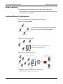
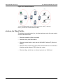
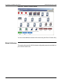
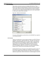
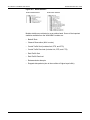
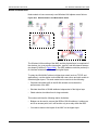
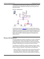
Standard Models User Guide
28—Wireless LAN Model User Guide
28 Wireless LAN Model User Guide
This document describes the Wireless LAN (WLAN) simulation model shipped
as part of standard OPNET model release. Note that the Wireless Module is
required for any simulations that use the WLAN model suite. This document
assumes that you are familiar with the WLAN protocol, however, for your
convenience, a brief overview of the protocol is included in section Wireless
LAN Background on page STM-28-14.
Model Features
This model is intended primarily for MAC performance estimation and is based
on information contained in the following documents:
• IEEE Std 802.11, 1999—Wireless LAN Medium Access Control (MAC) and
Physical Layer Specifications
• IEEE Std 802.11b, 1999—Wireless LAN Medium Access Control (MAC) and
Physical Layer Specifications: Higher-Speed Physical Layer Extension in the
2.4 GHz Band
Important features of the WLAN model are listed in Table 28-1.
Table 28-1 Wireless LAN Model Features (Part 1 of 3)
Model Feature
Description
Access mechanism
Carrier sense multiple access and collision avoidance
(CSMA/CA) distributed coordinating function (DCF) access
scheme as defined in the standard.
The point coordination function (PCF) access scheme, which
can be used in infrastructure network configurations, is also
supported.
Roaming
Mobile IP
Frame exchange
sequence
Data and Acknowledgment frame exchange to ensure the
reliability of data transfer. Optional RTS/CTS frame exchange
for media reservation.
Deference and backoff
Interframe spacing: DIFS, SIFS, EIFS for DCF, and PIFS for
PCF implementation. The values of the intervals are selected
based on the physical characteristics.
Binary exponential backoff.
Data rate
Modeler/Release 10.5
Data rates supported by the WLAN protocol are: 1 Mbps, 2
Mbps, 5.5 Mbps, and 11 Mbps.
STM-28-1
28—Wireless LAN Model User Guide
Standard Models User Guide
Table 28-1 Wireless LAN Model Features (Part 2 of 3)
Model Feature
Description
Recovery mechanisms
Retransmission mechanism for data frames used when the
acknowledgment frame is not received. Short and Long retry
counters as defined in the standard.
Fragmentation and
reassembly
Optional data frame fragmentation based on the size of the
data packet received from the higher layer. The fragments are
reassembled at the destination station.
Duplicate packet
detection
Tuple cache to store the information of the received packet so
that duplicate packets are discarded by the MAC layer.
Physical layer
Physical layer-dependent parameters (such as timing
intervals and backoff slots) are modeled in the WLAN MAC.
The following physical layer technologies from the IEEE
802.11 specification are modeled:
• Frequency hopping spread spectrum (FHSS)
• Direct sequence spread spectrum (DSSS)
• Infrared
The radio pipeline stages have the following modifications:
• Radio receiver—The receiver group of the station is
restricted to its subnet and the transmitting station does not
receive its transmitted packets. (wlan_rxgroup.ps.c)
• Channel match—The transmitter and receiver data rate
should match to successfully transmit a packet.
(wlan_chanmatch.ps.c)
• Power Stage—Packets with a received signal power below
the threshold (which is configurable) do not make the
receiver busy and the receiver treats such packets as noise
packets. This pipeline stage computes the received signal
power and considers the results of the channel match stage
when determining which packets are considered noise.
(wlan_power.ps.c)
• Error correction—If the receiving packet contains more
errors than permitted by the error threshold, the pipeline
stage marks it as a corrupted packet and the MAC layer
discards it. (wlan_ecc.ps.c)
STM-28-2
Modeler/Release 10.5
Standard Models User Guide
28—Wireless LAN Model User Guide
Table 28-1 Wireless LAN Model Features (Part 3 of 3)
Model Feature
Description
Communication Distance
and Spatial reuse
The maximum communication distance between two WLAN
nodes is a function of three parameters: the transmission
power of the sending node, the path-loss propagation model,
and the reception power threshold (receiver sensitivity) of the
receiving node. Based on the configured values of these
parameters, you can model WLAN networks in which the
communication distance is more than 300 meters. The IEEE
802.11 standard limits the distance between WLAN nodes to
300 meters. Therefore, WLAN networks that extend beyond
300 meters might incur a performance degradation in the
WLAN MAC algorithm.
The receiver sensitivity concept that is implemented through
the reception power threshold attribute enables spatial reuse
modeling with WLAN models. Packets with a reception power
that is lower than the threshold cannot make the receiver lock
onto their signal and will be treated as noise packets. When
the signal of these packets is very weak, the receiver can
simultaneously receive another packet with a strong signal
from a nearby neighbor. This means that if two sets of WLAN
nodes are far away from each other, they can act as two
different LANs but still use the same BSS ID and frequency
band (and therefore double the total available bandwidth).
Access Point
functionality
A station can be configured as an access point in an
infrastructure BSS network. All stations are capable of being
an access point, however, only WLAN bridges, switches, or
routers can connect a BSS to the distribution system—use
these nodes when you are configuring an ESS.
Radio IP auto-addressing
All WLAN nodes can be configured for IP auto-addressing. All
WLAN nodes in the same BSS belong to the same IP network.
If there is a static assignment, this assignment will be the
network address of all the nodes in the subnet. However, if
there is more than one static assignment and they have
different network addresses, the first static assignment that is
encountered becomes the network address of all the nodes in
the subnet.
Note: Wireline nodes use a different procedure for
auto-addressing that is independent of wireless IP
auto-addressing.
Buffer size
Data that the WLAN MAC received from a higher layer is
stored in a buffer. The buffer size is limited to the maximum
value set by the user. Higher layer packets are dropped after
the maximum buffer size is reached.
End of Table 28-1
Modeler/Release 10.5
STM-28-3
28—Wireless LAN Model User Guide
Standard Models User Guide
Model Limitations
The following protocol features are not included in the WLAN model.
• Roaming and PCF. Both of these features are implemented separately, but
they cannot be used together.
Supported Network Configurations
The WLAN model supports the following configurations:
Figure 28-1 Ad-hoc Network
This is an adhoc network of several stations. The workstations
can have peer-to-peer connections with other stations in the
BSS, but communication is limited to within the BSS.
Figure 28-2 Infrastructure BSS
Workstations communicate with each other
through the Access Point (AP).
Figure 28-3 Extended Service Set
Workstations communicate with each other and with nodes
outside their LAN through the Access Point (AP).
STM-28-4
Modeler/Release 10.5
Standard Models User Guide
28—Wireless LAN Model User Guide
Figure 28-4 Wireless Backbone
You can set a BSS Identifier for each router interface. Here, Router_1, Router_2,
Router_3, and AP form a wireless backbone, BSS 1.
wireless_lan Object Palette
The wireless_lan and wireless_lan_adv object palettes contain the node models
of the WLAN model suite.
• Wireless workstation (fixed and mobile)
• Wireless server (fixed and mobile)
• Wireless terminal station, which has the WLAN MAC without IP (fixed and
mobile)
• Wireless routers, which have one wireless interface and one or more wireline
interface such as ethernet, FDDI, token ring, or atm
• Wireless bridge, which has one ethernet port and one WLAN port
Modeler/Release 10.5
STM-28-5
28—Wireless LAN Model User Guide
Standard Models User Guide
Figure 28-5 wireless_lan Object Palette
You can create additional wireless LAN routers using the Device Creator utility.
Model Attributes
This section discusses the WLAN-related configurable parameters available as
part of WLAN model suite.
STM-28-6
Modeler/Release 10.5
Standard Models User Guide
28—Wireless LAN Model User Guide
Local Attributes
Each wireless node has the same set of wireless LAN attributes. These
attributes are grouped under the Wireless LAN Parameters compound attribute.
There is also a Wireless LAN MAC Address parameter, which is an internal
station address that is usually set as auto assigned unless specific configuration
is required. You can configure the WLAN parameters on a per-interface basis
for nodes with multiple wireless interfaces.
Figure 28-6 Wireless LAN Parameters
.
The various WLAN attributes and their effect on the WLAN MAC are explained
in the following sections.
RTS Threshold
Specifies a threshold that is used to determine whether or not RTS/CTS frame
exchange is required for a particular data frame. If the MAC service data unit
(MSDU), received from higher layers in the protocol stack, is larger than the
RTS threshold, RTS/CTS exchange is needed for medium reservation. The
default value for this attribute is NONE, which means that no RTS/CTS
exchange takes place regardless of the MSDU size. Note that although
RTS/CTS exchange is optional in the protocol, all stations should be able to
respond to the CTS sent by the remote station when necessary.
Enabling RTS/CTS frame exchange introduces additional overhead, which is for
the successful transmission of data frames. Although, RTS/CTS exchange
improves the reliability of data transmissions, the channel reservation time per
data frame might increase, which would lower the overall throughput in the LAN.
Modeler/Release 10.5
STM-28-7
28—Wireless LAN Model User Guide
Standard Models User Guide
Fragmentation Threshold
This attribute specifies a threshold that is used to determine if an MSDU needs
to be fragmented before transmission. If the size of the MSDU received from a
higher layer exceeds the threshold, the MDSDU is fragmented. The number of
fragments to be transmitted is calculated based on the MSDU size and the
fragmentation threshold. The default value for this attribute is NONE, which
means that fragmentation does not occur regardless of the MSDU size. The
destination station receives these fragments and stores them in the reassembly
buffer until all fragments have been received. Fragmentation and reassembly is
implemented using OPNET’s built-in SAR (segmentation and reassembly)
package.
Using fragmentation for larger sized packets improves the reliability of data
exchange between the stations. Since every data fragment requires an
acknowledgement, the overall frame exchange per MSDU is higher than it
would be without fragmentation. This additional overhead can reduce the overall
throughput of the LAN.
Data Rate
The WLAN model supports data transfer at 1 Mbps, 2 Mbps, 5.5 Mbps, and 11
Mbps. These data rates are modeled as the speed of the transmitter and
receiver connected to the WLAN MAC process. Each data rate is associated
with a separate channel stream, from the MAC process to the transmitter and
from the receiver to the MAC process. A station can transmit data packets only
at the configured data rate. However, it can receive data at any of the supported
data rates (1 Mbps, 2 Mbps, 5.5 Mbps, or 11 Mbps). Finally, all control packets
are transmitted at a data rate of 1 Mbps as specified by the standard.
Physical Characteristics
The IEEE 802.11 standard specifies three physical layer technology options:
Frequency Hopping, Infrared, and Direct Sequence. Frequency Hopping is the
default setting. The following MAC parameters are set based on the technology
selected for the physical layer:
• Backoff slot duration
• All interframe spacing values: SIFS, DIFS, EIFS, and PIFS
• Minimum and maximum contention window size (to select number of backoff
slots)
The sizes of the PLCP Preamble and Header are also based on the physical
layer technology selected.
STM-28-8
Modeler/Release 10.5
Standard Models User Guide
28—Wireless LAN Model User Guide
Packet Reception-Power Threshold
This attribute defines the received power threshold value (in Watts) for WLAN
packets that arrive at the radio receiver. Packets with received signal power
below the threshold do not make the receiver busy and the receiver treats these
packets as noise packets. These packets act as a source of interference to valid
packets, which are packets whose power is above the threshold. This attribute
enables you to model the clear channel assessment approach in a WLAN
network model.
Unless the default transmission power of 1mW is changed, all WLAN packets
should reach at their destinations with enough power to be considered a valid
packet, as long as the propagation distance between the source and destination
is less than 300 meters. This 300m limit is defined by the IEEE 802.11 WLAN
standard.
The value of the “high threshold trigger” of the statwires between the radio
receiver and the MAC module in the surrounding node model are overwritten by
the value of this attribute.
Short Retry Limit
This attribute indicates the maximum number of transmission attempts before a
data frame is discarded. This retry limit applies to a data frame whose MSDU
size is less than or equal to the RTS threshold (such as a frame for which
RTS/CTS exchange is not needed). The default value is 7 attempts.
Long Retry Limit
This attribute indicates the maximum number of transmission attempts before a
data frame is discarded. This retry limit applies to a data frame whose MSDU
size is greater than or equal to the RTS threshold (such as a frame for which
RTS/CTS exchange is needed). The default value is 4 attempts.
Access Point Functionality
This attribute toggles the on/off switch of the MAC’s access point functionality.
A WLAN node with an access point MAC acts as a relay for stations in the BSS.
If this WLAN node is also capable of routing, it can connect a BSS to the
distribution system. Note that there can be only one AP in a BSS. If you
configure more than one AP in a BSS, the simulation will terminate and a
message will be written to the simulation log indicating that multiple APs are
configured in BSS.
Channel Settings
This attribute specifies the minimum frequency and bandwidth of the four
transmitting and receiving channels. Each channel is associated with one of the
supported data rates (1Mbps, 2Mbps, 5.5Mbps, or 11 Mbps). The settings
specified in this attribute are used for all four channels, since they belong to the
same station.
Modeler/Release 10.5
STM-28-9
28—Wireless LAN Model User Guide
Standard Models User Guide
Buffer Size
This attribute specifies the maximum length of the higher-layer data arrival
buffer. After the buffer limit is reached, data received from the higher layer is
discarded until some packets are removed from the buffer.
Max Receive Lifetime
This attribute indicates the maximum time after which attempts to reassemble
the MSDU at the destination station are terminated. The timer starts when the
first fragment of the fragmented MSDU is received.
Large Packet Processing
This attribute is used when the MAC receives a higher-layer packet that is
bigger than the maximum allowed data size of 2304 bytes (18432 bits). This can
happen if MAC is running directly below a traffic source module (and not below
an IP layer). When the default value “Drop” is used, these large packets are
dropped and a message is written to the simulation log.
If this attribute is set to “Fragment,” the large packets are not dropped, but are
fragmented prior to transmission. When you set this attribute to “Fragment,” you
should also set the Fragmentation Threshold attribute to a value other than
NONE but smaller than 2304 bytes. Although the model supports fragmentation
for packets that exceed the maximum permitted data size, this feature is not part
of the IEEE 802.11 standard.
BSS Identifier
This attribute specifies the BSS that this node, WLAN interface, or WLAN port
belongs to. The default value for all WLAN nodes is “Not Used,” which means
that the entire subnet belongs to the same BSS. Either all or none of the nodes
in a network model can specify the value “Not Used” for this attribute. If you
configure a BSS Identifier for one node, you must also do so for the other WLAN
nodes in the network. Use this attribute when configuring a wireless backbone
network configuration as depicted in Figure 28-4 on page STM-28-5.
PCF Parameters
This compound attribute configures PCF functionality in the WLAN MAC layer.
If PCF functionality is disabled and the Access Point Functionality attribute is
enabled, this node’s BSS operates only in DCF mode. When this attribute and
the Access Point Functionality attribute are both disabled, this node will not be
a pollable MAC even if its BSS is configured to operate in PCF mode with
periodic occasions. Note that only the PCF Functionality sub-attribute affects
nodes that are not access points—the remaining sub-attributes apply only when
access point functionality and PCF functionality are enabled.
STM-28-10
Modeler/Release 10.5
Standard Models User Guide
28—Wireless LAN Model User Guide
Roaming Capability
This attribute indicates if this node can roam (that is, switch) to another access
point (AP) when the signal from the connected AP gets weak. Roaming is not
supported in an ad-hoc BSS or in a BSS that has PCF enabled. For these types
of BSSs, set this attribute to disabled.
When roaming is enabled, the node keeps track of the average number of
beacons received from its AP. When this number gets too low, it begins
searching for another AP by listening for beacons on another channel. When it
successfully receives two consecutive beacons from an AP, it switches to that
AP. If it cannot receive two consecutive beacons from an AP, it changes
channels and again starts listening for beacons and continues this process until
a new AP is located.
Simulation Attributes
WLAN AP Connectivity Check Interval
This attribute is used when the Roaming Capability attribute and the WLAN
Beacon Efficiency Mode simulation attribute are enabled. It determines when
the
Available Statistics
To analyze the performance of the WLAN protocol, several statistics can be
collected during simulation execution. Statistics can be collected on a per-node
or a per-module basis. The available node statistics are:
• Delay: End-to-end delay of all packets received by the node’s wireless LAN
MAC and forwarded to the higher layer.
• Load: Total number of bits received from the higher layer. Packets arriving
from the higher layer are stored in the higher layer queue.
• Media Access Delay: Total time (in seconds) that the packet is in the higher
layer queue, from arrival to the point when it is removed from the queue for
transmission.
• Throughput: Total number of bits sent to the higher layer from the MAC
layer. The data packets received at the physical layer are sent to the higher
layer if they are destined for this station.
Modeler/Release 10.5
STM-28-11
28—Wireless LAN Model User Guide
Standard Models User Guide
Figure 28-7 WLAN Statistics
WLAN Global Statistics
WLAN Node Statistics
Module statistics are collected on a per station basis. Some of the important
statistics available from the WLAN MAC module are:
• Backoff Slots
• Channel Reservation (NAV counter)
• Control Traffic Sent (includes Ack, RTS, and CTS)
• Control Traffic Received (includes Ack, RTS, and CTS)
• Data Traffic Sent
• Data Traffic Received
• Retransmission attempts
• Dropped data packets (due to the overflow of higher-layer buffer)
STM-28-12
Modeler/Release 10.5
Standard Models User Guide
28—Wireless LAN Model User Guide
Node Architecture
Node models of some commonly used Wireless LAN objects are as follows:
Figure 28-8 Wireless Station and Workstation Nodes
?
The Wireless LAN modeling of the MAC and the physical layer is comprised of
the wireless_lan_mac process, transmitter, receiver, and the channel streams
(as shown by the box in Figure 28-8). The ARP (address resolution protocol) is
an interface between the MAC and the higher layers.
To study the WLAN MAC without a higher-layer stack (such as TCP/IP and
applications), use the station node model that uses source and sink models to
simulate higher layers. This node model can be used to do the following:
• Generate controlled traffic in the WLAN network and evaluate the
performance of the MAC
• Simulate the effect of WLAN attributes independent of the higher layer
• Obtain shorter simulation time for large networks
This node model has the following station limitations:
• Bridges can be used to connect the BSSs of WLAN stations. A station can
act as an access point, but it will function only as a relay within the BSS.
• You cannot observe the impact of the MAC on the higher layer
Modeler/Release 10.5
STM-28-13
28—Wireless LAN Model User Guide
Standard Models User Guide
The higher layers are replaced by a bursty source and a sink process. There is
a MAC interface that is equivalent to the ARP in the client/server model. The
WLAN MAC process is independent of the higher layer as long as it has an
appropriate interface.
Figure 28-9 Wireless Router
The WLAN router shown in Figure 28-9 has one wireless interface and one
ethernet interface. When it is configured as an access point, which is the default
configuration, it can connect a BSS with a wireline distribution system. Do not
configure a WLAN interface as an access point if it is part of a WLAN backbone
network. When the wireless interface receives a data frame that does not
belong to the same BSS, it will send the data frame to the higher layer for
address resolution.
Wireless LAN Background
The wireless LAN protocol is based on the IEEE 802.11 and 802.11b standards.
The standard defines a medium access control (MAC) sublayer and three
physical (PHY) layers. The goal of the IEEE 802.11 protocol is to describe a
wireless LAN that delivers services commonly found in wired networks, such as
throughput, reliable data delivery, and continuous network connections.
The architecture of the IEEE 802.11 WLAN is designed to support a network
where most decision-making is distributed across the mobile stations. Some of
the basic components of the 802.11 based network are described below:
• Station: In IEEE 802.11 network a station is the component that connects to
the wireless medium. The station may be mobile, portable, or stationary.
Every station supports all station services, which include authentication,
deauthentication, privacy, and delivery of the data (MAC service data unit).
STM-28-14
Modeler/Release 10.5
Standard Models User Guide
28—Wireless LAN Model User Guide
• Basic Service Set (BSS): The IEEE 802.11 WLAN architecture is built around
a BSS. A BSS is a set of stations that communicate with each another. When
all of the stations in the BSS can communicate with each other directly and
there is no connection to a wired network, the BSS is called an independent
BSS (IBSS). An IBSS, which is also know as an adhoc network, is typically
a short-lived network with small number of stations that are in direct
communication range.
When a BSS includes an access point (AP), the BSS is no longer
independent and is called an infrastructure BSS, or simply a BSS. In an
infrastructure BSS, all mobile stations communicate with the AP. The AP
provides the connection to the wired LAN, if there is one, and the local relay
function within the BSS.
• Extended Service Set (ESS): An ESS is a set of infrastructure BSSs, where
the APs communicate among themselves to forward traffic from one BSS to
another. The APs perform this communication via a distribution system (DS).
The DS is the backbone of the WLAN and can be composed of wired or
wireless networks.
The IEEE 802.11b standard is an amendment to 802.11 that adds support for a
high-speed physical layer (PHY) extension in the 2.4 GHz band.
Medium Access Control
The IEEE 802.11 medium access control (MAC) supplies the functionality
needed to provide a reliable delivery mechanism for user data over wireless
media.
The first function of the WLAN MAC is to provide a reliable data delivery service
to the users. This is achieved through a frame exchange protocol at the MAC
level.
The second function of the WLAN MAC is to provide a fair mechanism to control
access to shared wireless media. The WLAN MAC performs this function
through two different access mechanisms:
• a contention-based mechanism, called the distributed coordination function
(DCF)
• a centrally controlled access mechanism, called the point coordination
function (PCF)
The third function of the WLAN MAC is to protect the data it delivers. This is
done through a privacy service, called Wired Equivalent Privacy (WEP), that
encrypts the data sent over the wireless medium.
Modeler/Release 10.5
STM-28-15
28—Wireless LAN Model User Guide
Standard Models User Guide
MAC Frame Exchange
The minimal MAC frame exchange consists of two frames: a data frame sent
from the source to the destination and an acknowledgement (Ack) frame sent
from the destination to the source. If the source doesn’t receive an
acknowledgment, it tries to retransmit the data frame after it observes
appropriate deference. There are retry limits associated with the frame
retransmission.
The protocol also suggests an optional use of request to send (RTS) and clear
to send (CTS) frame exchange between source and destination stations for
media reservation. RTS is transmitted from the source station to the destination
station and CTS is a response initiated by the destination station to the source
station. This initial handshake is followed by the minimal MAC frame exchange.
Basic Access Mechanism
The basic access mechanism is carrier sense multiple access with collision
avoidance (CSMA/CA) with binary exponential backoff. In this type of access
mechanism, a station listens to the medium before beginning a transmission. If
the medium is already carrying a transmission, the station that is listening does
not begin its own transmission. This is the CSMA portion of the access
mechanism. If two or more stations begin transmitting at the same time, there
will be a collision, which can cause one or more frames to be corrupted.
To avoid a collision, a station listens to the medium before beginning its own
transmission. If it detects an existing transmission, it enters a deferral period,
which is determined by binary exponential backoff algorithm. The binary
exponential backoff mechanism chooses a random number that represents the
amount of time that must elapse while the medium is idle—that is, until the
listening station can try to start transmitting again.
The IEEE 802.11 MAC uses collision avoidance rather than collision detection
for simultaneous transmissions and receptions. For this reason, the IEEE
802.11 MAC implements a network allocation vector (NAV). The NAV is a value
that indicates to a station the amount of time that remains before the medium
becomes available. The NAV is kept current through duration values, which are
transmitted in all frames. By combining the virtual carrier sensing mechanism
(using NAV) with the physical carrier sensing mechanism, the MAC implements
the collision avoidance portion of the CSMA/CA access mechanism.
Distributed coordination function (DCF) is a basic access mechanism described
in the protocol. It uses physical and virtual carrier sense mechanisms. If both
mechanisms indicate that the medium is not in use for an interval of DIFS
(distributed interframe space), the station starts transmitting the frame. If the
medium is busy, however, the backoff algorithm is applied. The transmission is
considered unsuccessful if no acknowledgement is received from the
destination. This may result in the retransmission of the frame.
STM-28-16
Modeler/Release 10.5
Standard Models User Guide
28—Wireless LAN Model User Guide
Centrally Controlled Access Mechanism
The centrally controlled access mechanism uses a poll and response protocol
to eliminate the possibility of contention for the medium. This access
mechanism is called the point coordination function (PCF). A point coordinator
(PC) controls the PCF. The PC is always located in an AP. In PCF operation,
stations ask the PC to register them on a polling list. The PC then regularly polls
the stations for traffic while delivering traffic to the stations. The PCF is an
optional part of the IEEE 802.11 standard that is built over the DCF and
operates simultaneously with DCF.
Modeler/Release 10.5
STM-28-17
28—Wireless LAN Model User Guide
STM-28-18
Standard Models User Guide
Modeler/Release 10.5