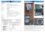
Download Tankmate 2 & Tankmate 160 Tank Contents Gauge User Guide
Transcript
User Guide
EUROGAUGE
...the level people
Tankmate 2 & Tankmate 160
Tankmate 2 & Tankmate 160
Tank Contents Gauge
User Guide
1/8
User Guide
EUROGAUGE
...the level people
Tankmate 2 & Tankmate 160
Tankmate Contents Gauge Head
Specification
Gauge Head:Flange
Bezel
Depth
Range
Materials
Accuracy
Zero Adjust
Calibration
Marks
Protection
Position
Fixing:
196mm dia.
160mm dia
59mm
0.6 - 10m W.G. at S.G 1.00
Case, Bezel & Back Plate:
Type 304 Stainless Steel
(Bezel Polished).
Gauge ± 2% of full scale.
Approximately 10% of F.S.D.
Major max.10 , Minor max.30.
IP65 (BS5490/IEC529).
Vertical Mounting.
3 holes 5.8mm dia.
equispaced on 178mm pcd.
TG Internal Transmitter:Diameter
178mm
Height
140mm
Housing
Mild or Stainless Steel
AG External Transmitter:Diameter
178mm
Height
100mm
Housing
Mild or Stainless Steel
Maximum Distance from Transmitter
to Gauge Head: 100 metres
Zero
Adjustment
Screw
1
/2”BSP Connection for
4mm o.d Copper Tube
1
/8”BSP Connection for
4mm o.d Nylon Tube
3
/4” or 1”
BSP Connection to
Tank
1
/2”BSP Tank Adaptor
for use with TG Internal
Tank Transmitter
AG External Tank Transmitter
Lifting
Cable
Air Bag
TG Internal Tank Transmitter
2/8
User Guide
EUROGAUGE
...the level people
Tankmate 2 & Tankmate 160
Questionaire for Tankmate Gauges
Name:
Contact:
Addr:
Date:
Ref:
Tank Dimensions
Rectangular Tank
Horizontal Cylindrical Tank
Vertical Cylindrical Tank
Length:
m
Diameter:
m
Diameter:
m
Width:
m
Straight Length:
m
Straight Height:
m
Height:
m
Dished End Depth:
or
Spherical Radius:
m
Dish Depth:
or
Spherical Radius:
m
Width
m
m
Length
mm
Knuckle Radius:
Knuckle Radius:
Straight Length
mm
Diameter
Height
Spherical
Radius
Diameter
Knuckle
Radius
Straight
Height
'An accurate gauge
depends on accurate
information'
Dish Depth
Position of Tank Gauge Connection
from Low End of Tank:
mm or
degrees
Tank Slope:
Knuckle
Radius
Spherical
Radius
m
Dish Depth
Contents:
Specific Gravity:
kg/l
Gauge Scale
Gauge Scale in:
litres
percent
tonnes
gallons
fractions
Full Mark @ 90%
or
%
Refill Mark @ 30%
or
%
Empty Mark @ 10%
or
%
m3
metres
other
(may incur extra charge)
Dial Marking:
Gauge Selection
Dial Diameter
TankMate 2
(Nylon Tube)
m
TG Internal Transmitter
(requires min. 200mm dia access into tank)
100mm
Tube Length:
Additional Information
Mild Steel:
160mm
Stainless Steel:
TankMate 160
(Copper or Stainless Tube)
AG External Transmitter
Copper Tube Length:
10m
15m
20m
30m
50m
100m
Stainless Tube
(6m minimum length then in 6m increments)
Connection Size
3
/4" BSP
Transmitter
Connection
Height:
1" BSP
Transmitter
Connection
Height
mm
Tank Base
3/8
User Guide
EUROGAUGE
...the level people
Tankmate 2 & Tankmate 160
Installation Schematic
Tankmate Gauge with
TG Internal Transmitter
40
50 60 70
80
90
30
100
20
110
10
0
120
Push-on fitting
1/ " BSP Taper
8
Part No. 963709
1/ " BSP Tank Adaptor
2
Part No. 000160001
Hook for Lifting Cable
Tank Top or Manhole Cover
Lifting Cable (St/Steel)
Part No. 952513
Length according
to tank height/
diameter
(Fix to tank top or
manhole cover)
Nylon tube. 4mm o.d.
Part No. 963708
Push-on fitting
1
/8" BSP Taper
Part No. 963709
Flange: 178mm dia. x 20mm
Mild Steel Part No.15013401
Stainless Steel Part No.15013402
Alternative
Solder Joint Connection
4mm o.d Copper Tube
Part No.
10m 9542 03
15m 9542 04
20m 9542 05
30m 9542 06
50m 9542 07
100m 9542 08
Brass Cap Nut
Part No. 1542 4501
Brass Solder Nipple
Part No. 1541 4501
Soft solder to tube
Nitrile Airbag
Part No. 15163001
10mm
Spigot Assy.
Part no. 152100102
Mounting Pillar
15mm dia x 50mm
Mild Steel Part No. 15014401
Stainless Steel Part No. 15014402
4/8
Rubber Compression Washer
Part No. 9231 4001
User Guide
EUROGAUGE
...the level people
Tankmate 2 & Tankmate 160
Installation - Tankmate Gauge with TG Internal Transmitter
1.
Check the gauge dial for correct calibration, depth and specific gravity
and check whether pointer is on zero.
If pointer is not on zero, carefully remove the front bezel from the gauge
and re-set the pointer to zero via the adjustment screw on the gauge dial.
2.
Mount the gauge in the required position. If mounting outdoors, the gauge
should be protected from direct sunlight.
3.
Remove the manhole cover from the tank and mount the tank adaptor
close to the manhole or in the cover itself. Attach the lifting cable to a
suitable fixing point at the top of the tank.
4.
Pass the nylon tube through the tank adaptor and connect it to the TG
external transmitter (if using copper tube then make connection in
accordance with diagram on page 4).
Important: This must be a 100% airtight connection.
5.
Run the tube to the gauge ensuring that there are no sharp bends or kinks
6.
Connect the tube to the gauge (if using copper tube then make
connection in accordance with diagram on page 4).
Important : This must be a 100% airtight connection.
7.
Lower the TG transmitter using the lifting cable (DO NOT USE THE TUBE)
to the bottom of the tank. Provided that airtight connections have been
made at both the transmitter and gauge ends, a correct indication will be
obtained and the gauge will maintain a constant reading of the liquid level.
8.
Attention: If for any reason the tube has to be disconnected, the
transmitter must be first removed from the tank to prevent the airbag in
the transmitter from collapsing.
If the airbag of the transmitter collapses due to an air leak in the system,
ensure that the airbag is re-inflated and assumes its normal rounded
shape with the tube disconnected. (Blow down the inlet on top of the
transmitter until resistance is felt).
Reconnect the tube to both transmitter and the gauge before the
transmitter is lowered back to the tank bottom.
5/8
User Guide
EUROGAUGE
...the level people
Tankmate 2 & Tankmate 160
Installation Schematic
Tankmate Gauge with
AG External Transmitter
40
50 60 70
30
80
90
100
20
110
10
0
130
Push-on fitting
/8" BSP Taper
Part No. 963709
1
Bleed Screw
Nylon tube
4mm o.d.
Part No. 963708
Side Wall
of Tank
Stop Cock
Alternative
Solder Joint Connection
4mm o.d Copper Tube
Part No.
10m 9542 03
15m 9542 04
20m 9542 05
30m 9542 06
50m 9542 07
100m 9542 08
3
/4 or 1" BSP
Spigot
Brass Cap Nut
Part No. 1542 4501
Spigot Assembly
Part no. 152100102
Brass Solder Nipple
Part No. 1541 4501
Soft solder to tube
Nitrile Airbag
Part No. 15163001
10mm
Rubber Compression Washer
Part No. 92314001
6/8
User Guide
EUROGAUGE
...the level people
Tankmate 2 & Tankmate 160
Installation - Tankmate Gauge with AG External Transmitter
1. Check the gauge dial for correct calibration, depth and specific gravity
and check whether pointer is on zero.
If pointer is not on zero, carefully remove the front bezel from the gauge and
re-set the pointer to zero via the adjustment screw on the gauge dial.
2.
Mount the gauge in the required position. If mounting outdoors, the gauge
should be protected from direct sunlight.
3.
Ensure that the stopcock on the tank is fully closed. Connect the AG transmitter to the stopcock. Ensure that the transmitter bleed screw is positioned
vertically at the top of the transmitter.
xxxxxxxxxxx
4.
Connect the nylon tube to the AG Transmitter (if using copper tube then
make connection in accordance with diagram on page 4).
Important : This must be a 100% airtight connection.
5.
Run the tube to the gauge ensuring that there are no sharp bends or
kinks.
6.
7.
Connect the tube to the gauge (if using copper tube then make
connection in accordance with diagram on page 6).
Important : This must be a 100% airtight connection.
Loosen bleed screw located in the top of the AG Transmitter.
8.
Open stopcock slowly until liquid begins to run out of the bleed hole.
9.
Retighten the bleed screw.
10. Turn the stop-cock fully on.
Provided that 100% airtight connections have been made at both the transmitter and gauge ends, a correct indication will be obtained, and the gauge
will maintain a constant reading of the liquid level.
11. Attention:
If the airbag of the transmitter collapses due to an air leak in the system,
ensure that the airbag is re-inflated and assumes its normal rounded
shape with the tube disconnected. (Turn off the stopcock, disconnect the
transmitter, drain out the liquid, blow down the inlet on top of the transmitter until resistance is felt).
Reconnect the tube to both transmitter and the gauge before the transmitter is lowered back to the tank bottom.
7/8
User Guide
EUROGAUGE
...the level people
Tankmate 2 & Tankmate 160
Troubleshooting
Problem
Cause
Action
No reading
Air Leak
Check that capillary tubing has been correctly fitted.
Constant reading
regardless of tank
contents
Diaphragm in
transmitter has
collapsed.
Make sure that the transmitter diaphragm has been
correctly inflated (blow down inlet on top of transmitter until resistance is felt). Then release pressure
and the diaphragm will assume its correct shape.
Slowly decreasing
gauge reading
Minute air leaks.
Check for splits or twists in the capillary tube.
Remake the capillary tube connections to the
gauge and to the transmitter.
Incorrect tank calibration.
Check calibration details against:
Diaphragm in transmitter
partially deflated.
1.
2.
3.
Gauge reading too low
Gauge dial.
Original order.
Eurogauge advice note.
Check diaphragm inflation (see above).
Gauge reading too high
Incorrect tank calibration.
Check the tank calibration as above.
Gauge in direct sunlight.
Re-mount gauge in a position where it is
not exposed to direct sunlight.
If in any doubt about any of the above please contact us on 01293 658360.
Do not attempt to dismantle gauge head as this is a factory adjustment only.
AFRISO EUROGAUGE LTD
Part Numbers
TM160
Capsule Range
A=100mbar (1m) D=400mbar (4m) G=Other
B=160mbar (1.6m) E=600mbar (6m) X=NA
C=250mbar (2.5m) F=1000mbar (10m)
Gauge Head Connector
1=4mm Nylon 2=4mm Brass 3=4mm St/Steel
Transmitter Type
·
·
·
·
·
·
·
·
·
·
·
·
·
RADAR and MICROPULSE
ULTRASONICS
PRESSURE TRANSMITTERS
VIBRATION SWITCHES
CAPACITANCE
Float Level Switches
Conductivity
Rotary Paddle
Magnetostrictive
Self-powered gauges
Oil/water Alarms
Leak Detectors
Pressure and Temperature
A=M/Steel Internal 4mm Nylon Connection
B=St/Steel Internal 4mm Nylon Connection
C=M/Steel Internal 4mm Brass Connection
D=St/Steel Internal 4mm St/Steel Connection
E=St/Steel External 1" BSP 4mm Nylon Connection
F=St/Steel External ¾" BSP 4mm Nylon Connection
G=St/Steel External 1" BSP 4mm Brass Connection
H=St/Steel External ¾" BSP 4mm Brass Connection
X=No Transmitter Required
Tank Adaptor
0=No Tank Adaptor
1=½" BSP Brass Tank Adaptor
2=1" BSP St/Steel tank Adaptor
TM160
Note: We reserve the right to amend specifications without prior notice.
8/8
User Guide
EUROGAUGE
...the level people
Tankguard 3 Fillpoint Tank Management System
The TankGuard 3 must be mounted on a flat vertical surface.
All wiring must be in suitable cable for the application conditions and must comply with the relevant electrical supply
authority regulations, together with any other statutory requirements which may affect the installation.
The 4-20mA signal cables should, if possible, be run separately from any cables carrying mains voltages.
It is recommended that cable with polyethylene or PVC insulation with a conductor size of at least 1.5mm2 is used.
If the 4-20mA signal cables are to be run through areas of high electrical interference it is recommended that screened
cable is used with the screens being terminated to the earth terminal in the TankGuard 3 unit.
Refer to the user guides for the tank level sensor and overfill alarm switch for their individual connection details.
Isolate Mains
Supply Before
Servicing !
Tankguard 3 External Wiring Connections
L N E
+ - + -
100-265Vac
In
Out
4 - 20mA
Remote
Alarm
or BMS
Overfill
Switch
Volt free contact to BMS or external alarm
Mains
Supply
4-20mA re-transmission to BMS
Tank Mounted
Overfill Alarm Switch
Voltage free
Tank Mounted
Level Sensor
4-20mA two wire
Declaration of Conformity
AFRISO EUROGAUGE LTD
Unit 4, Satellite Business Village
Fleming Way, Crawley
West Sussex. RH10 9NE
Tel: +44 (0)1293 658360
Fax: +44 (0)1293 528270
www.eurogauge.co.uk
[email protected]
Tankguard 3
This is to certify that the above named product(s) fully complies with the
Electromagnetic Compatability Directive 89/336/EEC and the Low Voltage Directive
73/23/EEC of the European Union and with the requirements of the normative
sections of the following harmonised European Standards.
EN50081-1:
EN50082-1:
EN 61010-1:
·
·
·
·
·
·
·
·
·
·
·
·
·
RADAR and MICROPULSE
ULTRASONICS
PRESSURE TRANSMITTERS
VIBRATION SWITCHES
CAPACITANCE
Float Level Switches
Conductivity
Rotary Paddle Switches
Magnetostrictive
Self-powered gauges
Oil/water Alarms
Leak Detectors
Pressure and Temperature
Electromagnetic Compatibility - Generic Emission Standard.
Part 1 : Residential, Commercial and Light Industry.
Electromagnetic Compatibility - Generic Immunity Standard.
Part 1 : Residential, Commercial and Light Industry.
Safety requirements for electrical equipment for measurement,
control and laboratory use.
Signed :
D. C Ward
Position:
Date:
Technical Services Manager
01/04/2009
This declaration applies to the following part number(s):
200130000
EUROGAUGE
...the level people
User Guide
Tankguard 3 Fillpoint Tank Management System
The TankGuard 3 is a Fillpoint Tank Management System.
Originally designed to comply with all Health and Safety
Standards relating to Fuel Oil Installations, the system has
been extended to incorporate specific requirements of the
various Military, Health and Local Authority users as well
as Government and modern Industry. X
The system complies with M & E III and other related
specifications and can be used with any level measuring
device powered by a 4-20mA current loop. The unit may
also be configured for use with any other non looppowered level measuring device which provides a 420mA output.
X
This makes TankGuard 3 a universally applicable system
providing the user with total flexibility to apply the most
reliable type of level sensor element such as capacitance,
ultrasonic, pressure, float, intrinsically safe or standard to perform a reliable measuring task.
The TankGuard 3 features an attractive wall-mounting weatherproof housing to IP65 and requires no other
cabinet or housing enclosure. It incorporates an easy to read % analogue dial trend indicator to give 'at-aglance' information of the level in the tank. The red LED digital display provides the user with the current tank
volume and an internal sounder and large LED lamps give warnings of re-order, high level and overfill alarm
conditions. XThe overfill alarm input is via a separate level sensor such as a float or capacitance level switch for
safety.XXXX
System TEST and MUTE buttons are purposely situated for easy operation and the added REFILL VOLUME
button is particularly useful for re-ordering purposes and also provides the delivery driver with a check facility to
tell him that he can safely discharge the full delivery load into the tank.X
The system provides a 4-20mA re-transmission output and also voltage free contacts for connection to a BMS
system. A version with GSM monitoring is also available.
The Tankguard 3 is supplied factory calibrated to suit any tank shape.
Typical Tankguard 3 Installation
Tank
Overfill
Alarm
(Floatswitch)
Tank Level
Indicator/
High & Refill
Alarms
(DMU08 Pressure
Transmitter)
Tank
FillPoint
Digital indication and control instruments
VarioFox 12 / 14 in wall mounting enclosures
01
• Compact and ready-to-connect
Screw connector set
Junction box with
pressure relief port
• 5-digit graphic LCD display
• Text-orientated menu user guide
02
Digital
indicator
VarioFox
• Freely selectable measurement
units
• Integrated transducer supply
03
• 2 or 4 relay switching outputs
Alarm
instrument
• Data logger function
04
05
06
07
08
09
10
11
12
13
14
15
Pressure transducer
DMU 08
Description
Compact, ready-to-connect indication and control instrument with
digital display, housed in a robust
wall mounting enclosure. With integrated transducer supply and 2
relay outputs. VarioFox forms in
conjunction with an electronic measurement transducer (e.g. for pressure, temperature, level, etc.) a
stand-alone measurement and control system. VarioFox is universally
applicable and can be freely configured.
Operating temperature range
Ambient:
-10 °C/+55 °C
Technical specifications
Visual alarm
1 red LED
Display
5-digit graphic LCD display with
white background lighting and textorientated menu guide.
Selectable operating and display
languages: German / English / French.
Also freely selectable measurement
units.
Measuring range
99,999...- 9.999 (start and end of
scale values as well as decimal
point freely adjustable)
Linearity
±0,1 % of measuring range
Resolution
10 Bit,
decimal point freely adjustable
Response time
< 0,2 secs, filter facility
38 Division II
Supply voltage
AC 50 –253 V
DC 20 –253 V
Sensor supply
Integrated, galvanically isolated
power supply for transducer:
DC 20 V/20 mA
Sensor inputs
All standard analogue signals,
e.g. 4 – 20 mA, 0 – 20 mA, 0 –10 V.
Transistor (PNP, e.G. for VibraFox GVG)
Audible alarm
Integrated piezo buzzer, can be
muted
Analogue output 1
0/4 –20 mA, galvanically isolated
Analogue output 2
0–10 V, galvanically isolated
Switching outputs
Relay contacts: 2 voltage-free
changeover
(adjustable hysterisis)
Contact rating: AC 250 V
2A 100 VA
For the complete range of 'Digital
Indication Instruments', see pages
519 to 521.
Housing
Robust wall mounting housing from
impact resistant plastic (ABS)
W x H x D: 100 x 188 x 65 mm
Protection: IP 54 (EN 60529)
Linearisation
Customer specific linearisation with
maximum 24 points, e.g. for volume
display (litres) in non-linear vessels.
Dip charts for horizontally installed
cylinders as well as for spherical
tanks are pre-programmed.
Min./Max. value memory
The highest and lowest values reached during operation can be called
up.
Data storage and clock
Data memory for long-term monitoring on memory card (SD/MMC).
Memory card is not part of scope of
supply.
Optional
• 4 relay output contacts
DG: H
Part no. Price €
VarioFox 12
(2 relay contacts)
31235
VarioFox 14
(4 relay contacts)
31236
SD memory card
31237 on request


