1
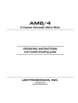
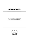
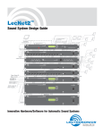
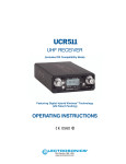
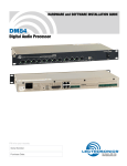
UDR200C
RATIO DIVERSITY UHF RECEIVER
OPERATING INSTRUCTIONS
and troubleshooting guide
LECTROSONICS, INC.
Rio Rancho, NM
www.lectrosonics.com
Table of Contents
GENERAL TECHNICAL DESCRIPTION ............................................................... 4
FRONT PANEL CONTROLS AND FUNCTIONS ................................................... 7
REAR PANEL CONTROLS AND FUNCTIONS ..................................................... 8
INSTALLATION AND OPERATING INSTRUCTIONS ............................................ 9
USING THE LED INFORMATION DISPLAY ....................................................... 10
UDRPANEL SOFTWARE ..................................................................................... 12
ANTENNA USE AND PLACEMENT ................................................................... 17
TROUBLESHOOTING .......................................................................................... 18
UDR200C REPLACEMENT PARTS and ACCESSORIES ................................. 19
LecNet COMPUTER INTERFACE ....................................................................... 20
LecNet SOFTWARE PROTOCOL ........................................................................ 21
SPECIFICATIONS AND FEATURES .................................................................. 24
SERVICE AND REPAIR ....................................................................................... 25
RETURNING UNITS FOR REPAIR ..................................................................... 25
WARRANTY ............................................................................................ Back cover
GENERAL TECHNICAL DESCRIPTION
The UDR200C consists of two high performance, triple-conversion receivers operating simultaneously. The audio outputs of
the receivers are blended in a ratio controlled by the comparative RF levels in the receivers. The multistage RF front end is
a unique design that is tuned by a microprocessor to the
selected frequency. The RF and audio performance is extremely stable over a very wide temperature range, making the
UDR200C perfectly suited to mounting in studio equipment
racks. The proprietary audio processing includes a dual-band
compandor and dynamic noise filter for very low distortion and
a superior signal to noise ratio. The squelch system is operated by a separate pilot tone and mutes the audio output
directly at the output connector. The audio output is calibrated
for exact level matching, with wide range, peak responding
LED indicators.
RF SECTION
The problem posed to the design staff was to retain the RF
reliability of the Lectrosonics’ fixed frequency designs but add
the frequency flexibility of a frequency agile design. The universal (and poor) way to build frequency agile systems is to
design a wide open front end that will pass any frequency
within the tuning range of the system. This leads to very poor
RF performance with lots of interference, driving the user to
switch frequencies in an attempt to sidestep the interference.
This makes frequency agile receivers a self fulfilling system;
you have to use the frequency agility to get away from the
problems caused by the frequency agile design compromises.
The problem of frequency agility is further compounded when
you realize that frequency changes “on the fly” cannot be
made on any type of wireless system. For example, if there is
suddenly an interference problem with a system in use, on
stage for instance, a frequency change cannot be made
without interrupting the program. Basically, the show must go
on. In multichannel applications, changing the frequency of
one system will usually produce all kinds of new
intermodulation problems with the other systems operating in
the same location. Frequency agility is not the universal
panacea for interference problems. It is only another tool and
RF Module
Amp
71 MHz
IF Amp
Amp
Filter
FREQUENCY TRACKING FRONT-END
Our solution to the wide open front end problem was to design
a selective front end that can be tuned to the frequency in use.
Since we wanted this front end to be equivalent to our fixed
frequency front ends, this was a daunting task. Lectrosonics
has always used front ends with more sections and much
more selectivity than any other wireless manufacturer. The
final design consisted of a total of 12 transmission line resonators with variable capacitance applied to each resonator by a
microprocessor. This allows each resonator to be individually
tuned by the microprocessor for any user selected frequency
in a 25 MHz band. This sophistication produced a front end
that was as selective as fixed frequency designs, yet could
cover the entire 25 MHz range.
HIGH CURRENT LOW NOISE AMPLIFIERS
The gain stages in the front end use some rather special
transistors in a feedback regulated high current circuit that
combine three parameters that are generally at odds with one
another. These are: low noise, low gain and relatively high
power. It is easy to understand the advantages of low noise
and high power capability but why is low gain desirable? The
answer is that in a receiver, low gain allows the front end to
handle stronger RF signals without output overload, which is
“increased headroom,” so to speak. The result of a design that
takes all three of these parameters into consideration at once,
is a low noise RF amplifier with a sensitivity rating equal or
better than the best conventional design with a hundred times
less susceptibility to intermodulation interference.
Combining the high power gain stages with the tracking front
end produces a receiver that is unusually immune to single
and multiple interfering signals close to the operating frequency and in addition strongly rejects signals that are much
farther away.
UDR200C
BLOCK DIAGRAM
RF Level
LEDs
Saw
Filter
Filter
a limited tool at that. The first line of defense must be the
system’s basic immunity to interference. That required a new
look at frequency agile receiver design.
2nd Mixer
10.7 MHz
3rd Mixer
& IF Amp
300kHz
Counting
Detector
Center
Frequency
Detector
Filter
uP
Headphone
Out
50KHz
LP Filter
Tri-Mode
Dynamic
Hi-Level
Diode Mixer
uP
uP
Filter
1st Local
Oscillator
E2 PROM
Freq
Select
RF
Only
uP
Synthesizer
2nd Local
Oscillator
Filter
Xtal
Controlled
3rd
Oscillator
Ratio
Combiner &
Opti-Blend
2:1
Expander
Treble
Variable
Cut-Off
LP Filter
23KHZ
LP
Filter
Audio
Amp
2:1
Expander
Bass
Amp
Amp
Filter
Filter
Filter
71 MHz
IF Amp
uP
4
uP
50KHz
LP Filter
HI-LEVEL
DIODE MIXER
Saw
Filter
2nd Mixer
10.7 MHz
RF Level
LEDs
3rd Mixer
& IF Amp
300kHz
Center
Frequency
Detector
Counting
Detector
uP
Output
Level
Adjust
XLR
Out
Pilot
Tone
Mute
uP
To Data
Display
Wireless Diversity Receiver
DOUBLE BALANCED DIODE MIXERS
In all wireless receivers, a mixer is used to convert the carrier
frequency to the IF frequency where most of the filtering and
gain in the receiver takes place. After doing all the right things
in the front end, it would be a shame to waste the performance
with a second rate mixer. In other designs that is exactly what
happens since mediocre mixers cause more intermodulation
problems than mediocre front ends. The only solution was a
high power, double balanced diode mixer driven by a local
oscillator with more output power than most wireless transmitters (100 mW). The mixer in the UDR200C produces output at
only the sum and difference signals, with minimal spurious
signals. This mixer offers a very high overload threshold. The
IF output of this mixer is at 71 MHz which is unusually high for
a wireless receiver. This high frequency was chosen to increase the image rejection in the front end to as high as our
fixed frequency designs. The mixer is followed by low noise
amplifiers and SAW filters to preserve the superior RF performance.
SURFACE ACOUSTIC WAVE FILTER
The UDR200C is unique in that it uses a state of the art SAW
filter in the IF section. The SAW filter is the only filter that can
combine sharp skirts, constant group delay, and wide bandwidth in one filter. Though expensive, this special type of filter
allows us to follow the basic receiver rule of doing the primary
filtering as early as possible, at as high a frequency as possible and before high gain is applied to the signal. Since these
filters are made of quartz, they are very temperature stable.
Conventional LC filters at these frequencies don’t begin to
perform as well and in addition would drift unacceptably in the
elevated temperatures of an equipment rack. After following
the rule in a rigorous way, and due to the sharp filtering action
of the SAW filters, the 71MHz signal is converted to 10.7Mhz
and then to the low frequency of 300 kHz. Lots of gain is then
applied in a conventional IC and the signal is then converted to
audio. 300 kHz is very unconventional for a second IF in a
wide deviation (±75 kHz) system. We chose to use 300 kHz to
obtain an outstanding AM rejection figure over a very wide
range of signal strengths and to produce an excellent noise
improvement at low signal strengths (capture ratio). To use an
IF at 300 kHz requires an unusual circuit to convert the IF to
audio.
DIGITAL PULSE COUNTING DETECTOR
The UDR200C receiver uses an advanced digital pulse detector to demodulate the FM signal, rather than a conventional
quadrature detector. The common problem with quadrature
detectors is thermal drift, particularly those that operate at
higher frequencies like 10.7 MHz. Though the quadrature
detectors may work well at room temperature, if they are not
carefully compensated, they will produce amplitude changes
and audio distortion in the elevated temperatures of an equipment rack. Some manufacturers try to get around the problem
by tuning their systems at higher temperatures after they’ve
been on for some time. This just means that for the first hours
in a cool room the receiver is well out of specification or after a
few hours in a hot rack.
The UDR200C design presents an elegantly simple, yet highly
effective solution to this age old problem. The UDR200C
detector basically works like this: A stream of precision pulses
is generated at 300KHz locked to the FM signal coming from
the 300 kHz IF section. The pulse width is constant, but the
timing between pulses varies with the frequency shift of the FM
signal. The integrated voltage of the pulses within any given
time interval varies in direct proportion to the frequency modulation of the radio signal. Another way of describing it is that
as the FM modulation increases the frequency, the circuit
produces more pulses and as the modulation decreases the
frequency, the circuit produces fewer pulses. More pulses
produces a higher voltage and fewer pulses a lower voltage.
The resultant varying voltage is the audio signal.
This type of detector eliminates the traditional problems with
quadrature detectors and provides very low audio distortion,
high temperature stability and stable audio level. The counting
detector also adds additional AM rejection, in addition to the
limiting in the IF section. The amplitude of the pulses is constant, so level differences in the IF signal do not affect the
pulse. The two resulting audio signals from the A and B receiver channels are then combined to achieve the maximum
benefits of diversity reception.
RATIO COMBINING DIVERSITY WITH OPTIBLENDTM
Instead of the usual audio switching between the two receivers, we blend the audio outputs of the receivers in a ratio
controlled by the RF level of the received signals in the two
receivers. This totally eliminates any of the switching noise
sometimes heard in other designs and improves the signal to
noise ratio an additional 6 dB under weak signal conditions
and 3 dB in strong signal conditions.
TRI MODE DYNAMIC FILTER
After being combined in the Opti-Blend circuit, the audio signal
is passed through a “dynamic noise reduction circuit”. The
cutoff frequency of this filter is varied automatically by measuring the amplitude and frequency of the audio signal and the
quality of the RF signal. The audio bandwidth is held only to
that point necessary to pass the highest frequency audio
signal present at the time. If the RF level is weak, then the
filter becomes more aggressive. This results in a dramatic
reduction of “hiss” at all times. During passages with a high
frequency content, this filter gets completely “out of the way”
and passes the signal with no decrease in high-frequency
response. Keep in mind that if hiss is added to a signal, there
is a psycho acoustic effect that makes the sound seem
brighter. The other side of this is that if hiss is removed from a
signal it will sound duller. Basically the ear’s detection apparatus is pre-sensitized to high frequency sounds by small
amounts of high frequency hiss. Consider this effect when
making a judgment about the sound quality of various wireless
systems and this particular filter. We have satisfied ourselves
through elaborate tests that this filter is totally transparent.
There is one circumstance where a good argument can be
made for bypassing this filter, so a switch is provided to do just
that.
Rio Rancho, NM – USA
5
RF ONLY NOISE FILTER
A small switch on the rear of the receiver will allow the noise
filter to be set for RF ONLY. In this mode the filter is held out
of the audio frequency range unless the RF level drops to very
low levels. At weak RF levels, the filter operates in the TRI
MODE state until the RF level rises back to acceptable levels.
This has the desirable effect of softening dropouts. We recommend using the RF ONLY setting when it is desirable to pick
up high frequency background noise, such as for a location
shot for a movie. This might be machinery noise, compressed
air, etc. If the desirable background noise is at a low level, the
Tri Mode Dynamic Filter will identify this as undesirable hiss
and effectively remove it.
2:1 EXPANDER (Dual–Band Compandor)
“Dual-band Companding” is a complimentary system, that is,
whatever is done in the transmitter must be exactly mirrored in
the receiver. The transmitter compresses the audio signal in
two separate audio bands using four separate time constants
to avoid the inevitable trade-offs in attack and decay times that
occur in a single-band compandor. The companion circuit in
the receiver then re-expands this compressed signal restoring
the original dynamic range and frequency characteristics of the
signal.
The mixed audio signal leaves the Opti-Blend circuit and is fed
through a 23 kHz low pass filter where all the high frequency
noise (including the 32 kHz pilot tone) is filtered out. After the
23 kHz low pass filter, the signal is split into two parts via a 1
kHz low pass filter and a 1 kHz high pass filter. The separated
signals are then processed in separate channels of the 2:1
expander. Each channel of the 2:1 expander is optimized for
its respective frequency band. By optimizing the compandors
for high and low frequencies we can handle sounds such as
clicks, sibilants and fast transients produced by plucked or
struck instruments in the high frequency section without compromising the performance in the main voice range. The two
outputs of the 2:1 expander are then summed in an op-amp
and sent to an audio amplifier as one signal.
PILOT TONE MUTE (SQUELCH)
The 200 system utilizes a separate ultrasonic tone modulation
of the basic carrier to operate the receiver squelch. In the
transmitter, a 32.765 kHz tone is injected into the audio signal
after the microphone preamp, just after the compandor. The
supersonic pilot tone is filtered out of the audio signal immediately after the detector in the receiver so that it does not
influence the compandor or various gain stages.
The basic benefit of the pilot tone squelch system is that the
receiver will remain squelched (muted) until it receives the pilot
tone from the matching transmitter, even if a strong RF signal
is present on the carrier frequency of the system. Once a pilot
tone is detected, the receiver will remain open during all signal
conditions. If the transmitter signal degrades to the point
where hiss and noise may become objectionable, the Opti-
6
Blend circuitry and Tri Mode Dynamic Filter will work to reduce
or eliminate the unwanted noise. Since the pilot tone keeps
the receiver audio output open, as soon as the transmitter
signal returns to normal, the audio signal is instantly available
with no delays. A conventional squelch system, on the other
hand, can briefly interrupt the audio during a near dropout
condition.
The pilot tone mute circuit drives a relay which physically
disconnects the output amplifier from the output audio transformer. The relay then connects the transformer primary to
ground to prevent hum pickup in the transformer due to an
open primary winding. This provides complete muting of the
audio and the noise. The pilot tone function may be bypassed
with a rear panel push button. Once pushed, the pilot tone
mute is “latched” in a disabled condition until the receiver is
powered off then back on. When the pilot tone is disabled,
there is still a “squelching” function provided by the Opti-Blend
circuitry and Tri Mode Dynamic Filter. These circuits can
provide approximately 50 dB of muting during weak or no
signal conditions when the pilot tone is disabled. If you hear
moderate hiss when the transmitter is off, the pilot tone has
probably been bypassed.
AUDIO OUTPUT
The audio is a fully floating, transformer coupled, balanced
signal. Pin 2 is “high” or in phase with the transmitter input. A
precision attenuator allows you to adjust the output level from
+15 to -40 dBu. The output always runs “wide open” and is
only attenuated by this output level control. Neither the noise
level in the receiver nor headroom is affected. You can, however, over drive or under drive attached audio equipment.
A ground lift switch is available to disconnect pin 1 of the 3 pin
XLR if a hum loop is encountered. Never, never cut off the
ground plug on the AC cable. The ground lift switch will accomplish the same audio results without the safety hazard.
If a single ended output is necessary, pin 3 (or pin 2) must be
tied to ground, preferably at the end of the cable with the
single ended connector. Other Lectrosonics equipment is not
transformer coupled and will work without the pin 3 ground
connection. This fully floating output will not.
The headphone output is a high quality signal derived from 4
high current op amps operating in parallel to provide a low
noise, low distortion signal. This output can be used as an
unbalanced output if needed. Unlike the rear panel balanced
output, this output can be overdriven if the headphone volume
control is set too high. As with any headphone output, keep
the sound levels in the headphones at a moderate level.
When the output is not being used, turn it all the way down.
Be careful to not turn up the headphone gain if the receiver is
muted or squelched. As with any output that is muted, there is
no way of knowing what the level will be when the receiver
audio is opened.
Wireless Diversity Receiver
FRONT PANEL CONTROLS AND FUNCTIONS
TRANSMITTER AUDIO LEVEL
PILOT INDICATOR
The modulation (audio level) of the incoming signal is indicated
by a fast responding LED strip. The strip is calibrated in 6dB
steps over an expanded scale (54dB) which provides an
extremely accurate visual “picture” of the signal dynamics,
even at a distance away from the receiver. The LED strip is
fast enough to track even brief transients, easily exceeding the
response time of conventional VU meters.
The audio output muting (squelch) function of the UDR200C is
controlled by a 33kHz tone modulation of the RF carrier. The
audio output is muted until this tone is present. The muted
condition is indicated by a blinking TX switch setting in the
LED display.
RF LEVEL INDICATORS
Two separate LED strips are provided to indicate the level of
the incoming RF signals. The LED strips are calibrated to
provide accurate indications from 1uV to 1mV. The LEDs are
highly visible from a distance, making antenna set up more
accurate. The dual LED strips are especially useful in “troubleshooting” difficult antenna installations.
OPTI-BLEND LEDs
The UDR200C receiver operates with a method of audio ratio
blending of two audio outputs. RF level in each receiver is
compared and the audio signals from the two receivers are
mixed together in a ratio that favors the quieter receiver. As
this blending action occurs, the brightness of the two OPTIBLEND LEDs will vary. The brighter the LED, the more audio
is being mixed in from that receiver.
FULL INFORMATION DISPLAY
The UDR200C receiver includes a 16-segment LED character
strip that provides information about the selected frequency,
group, required transmitter setting, TV channel, assigned user
name, locked/unlocked status and pilot tone status.
The pilot tone function can be defeated by pressing a switch
on the rear panel. The PILOT indicator, however, operates the
same regardless of whether or not the defeat switch is
pressed. The PILOT indicator strictly indicates the presence of
the pilot tone carrier from the transmitter.
DIVERSITY MODE
This switch is set to the DIVERSITY position for normal operation. For troubleshooting or when the receiver is used with a
single antenna, the switch can be set to select a single antenna only.
MONITOR
This is an audio output to drive a wide variety of different types
of headphones. It is also usable as a second high quality
audio output to drive recorders or external audio devices.
POWER
Pressing the upper half of the rocker switch applies power to
the receiver. At turn on, there are various relays and delays
built into the receiver to allow various stages to stabilize before
the audio output is activated. This will prevent an audio
“thump” when powering up the receiver and/or the transmitter.
The UDR200C has a universal switching power supply which
will operate on AC voltages from 95 to 240Volts, 50 or 60Hz.
A
1uV
2
5
10
25
50 100
RF LEVEL
6 6 8 . 1 0 0
1uV
2
5
10
250
500 1mV
8 . 7 V
RF LEVEL
25
50 100
OPTI
BLEND
-48
-42
-36
-30
-24
-18
-12
-6
0
LIM
TX AUDIO LEVEL dB
FREQ
SELECT
1 9
DIVERSITY
250
500 1mV
OPTI
BLEND
A
B
B
MODE
MENU
MONITOR
POWER
UDR200C Front Panel
Rio Rancho, NM – USA
7
REAR PANEL CONTROLS AND FUNCTIONS
AUDIO OUTPUT
ANTENNA JACKS
A calibrated control on the rear panel adjusts the output level
in 5 dB steps, referenced in dBu. This control knob adjusts the
absolute output level at the XLR connector. The AUDIO OUTPUT level control is located after the output transformer. This
allows the signal to noise ratio to remain constant regardless
of the setting of the control. As the audio level is reduced, the
noise is also reduced maintaining the same ratio.
These are standard 50 Ohm BNC terminals for the RF input to
the receiver.
PHASE REV
This switch reverses the polarity of the audio output signal.
The "0" setting corresponds to a positive signal at the transmitter input producing a positive output on pin 2 of the XLR audio
output connector.
AC POWER SUPPLIES
The UDR200C has a universal switching power supply which
will operate on AC voltages from 95 to 240 Volts, 50 or 60 Hz.
There is no external fuse since the power supply is self protected against line transients, short circuits, and over current
conditions.
EXPANSION OUT, EXPANSION IN
These miniature jacks provide the serial port interface for
multichannel systems in a “daisy chain” manner. The receiver
that connects to the computer uses the IN jack to receive
signals and information from the OUT jack on the next receiver
in the chain.
See the interconnect diagram on the next page.
PILOT TONE BYPASS
This switch defeats the audio output muting and triggering
action of the pilot tone. When the pilot tone is bypassed, the
Opti-Blend and the Variable Cutoff Low Pass Filter will still
provide a squelching action during weak signal conditions.
These circuits will still provide approximately 50 dB of muting
when the pilot tone is bypassed. When bypassed, a warning
message is displayed on the front panel LED character strip.
NOISE FILTER
EXT DC IN
The primary purpose of this jack is to provide battery backup in
case of a loss of normal AC power. The receiver will accept
power from this jack under two conditions. The first is whenever the front panel power switch is in the OFF position and
the second is when the front panel power switch is in the ON
position and the normal AC power fails or is removed. This
jack can also be used to provide normal DC power to the
receiver, if desired, although the power switch OFF position
will not function as expected. When using this jack to provide
normal DC power the receiver will always be ON regardless of
the position of the front panel power switch.
The external DC source can be 11 to 17 VDC. Pin 4 is positive
and pin 1 is ground. This jack will accept a standard 4-pin
female XLR connector. The relays and power supply stage
are fully protected by automatic reset poly fuses. The ground
side of the power supply is protected with a self resetting poly
fuse in case the UDR200C is connected to a positive ground
device through the audio cabling. The poly fuse will trip to
protect the receiver and the offending ground path can then be
removed.
LecNet (RS232) JACK
This 3.5mm stereo mini jack provides the serial connection
between the receiver and the computer. A stereo mini to DB9
cable is supplied with the receiver.
A sophisticated dynamic noise reduction filter can be switched
to operate in two different modes. The most effective mode is
the “TRI MODE DYNAMIC”. This mode derives a signal that is
proportional to the high frequency content of the desired audio
signal multiplied by the amplitude of the desired audio signal
and divided by the RF noise level. This derived signal controls
a proportional low pass noise filter that responds to transient
high frequency signals in less than a millisecond; this speed is
commonly accepted as much faster than the human ear can
resolve. Basically, the filter gets out of the way of high frequency audio information so quickly that the ear cannot detect
its operation. In addition this filter reduces high frequency
room noise and also the electronic microphone noise that is
present to some extent in all small electret microphones.
It may sound as if the filter is dulling the sound but this is a
well known psycho acoustic effect of reducing high frequency
noise. The ear is sensitized or fooled by hiss to “hear” more
high frequencies. The second mode, “LOW RF ONLY”, operates the filter only when the RF link between transmitter and
receiver is unusually weak, less than 5uV at the receiver
antennas. This is a relatively rare circumstance and so the
noise filter is effectively out of the circuit except when absolutely needed.
8
M
1
2
1
2
dBu
-5 0
5
-10
3
3
PHASE
-15
4
0 180
AUDIO OUTPUT
2
3
8
LecNet
6
7
4
5
2
3
PILOT
TONE
1
(RS232)
BYPASS
EXPANSION
10
15
NOISE FILTER
-25 -30 -35
ANT B
UDR200C Rear Panel
8
1
-40
-20
90 - 240 VAC
6
7
5
GND LIFT
4
IN
OUT
EXT DC IN
+11 TO 17V
TRI MODE
DYNAMIC
LOW RF
ONLY
ANT A
Wireless Diversity Receiver
INSTALLATION AND OPERATING INSTRUCTIONS
1) Locate a suitable operating location where the receiver will
not be subjected to extreme temperature variations and
possible bumps and drops. Try to route all wiring so it will
not cross walkways or isles.
6) Turn the unit on with the front panel POWER switch and
check to see that the PILOT indicator is blinking indicating
that the pilot tone is not being received (be sure the transmitter is turned off.)
2) Connect the power. For AC operation, connect the power
cord to the AC input jack on the rear panel and plug the
other end into a suitable electrical outlet. If 11 to 17V DC
operation/battery backup is desired, a power cord will need
to be fabricated. Use a standard 4-pin female XLR connector for the receiver end. Pin 4 is positive and pin 1 is
ground. Make the length of the DC cable long enough to
suit your installation and prepare and connect the source
end of the cable.
7) Set the operating frequency on the transmitter and receiver. (See “Using the LED Information Display” below.)
3) Attach the antenna cables to the BNC jacks on the rear of
the UDR200C and place the antennas. Best performance
will be obtained if the antennas are placed at least 3 feet
from each other. Try to mount them as high as possible
with a direct line of sight path to the transmitter if possible.
4) Set the Audio Output level control to minimum (CCW) and
connect the Audio Output XLR jack to the mixer input. Pins
2 and 3 of the XLR jack are HI and LO and can be reversed with the Phase switch, pin 1 is common.
5) Preset the following controls:
MODE (front panel) to DIVERSITY
MONITOR (front panel) to minimum (CCW)
PHASE (rear panel) to 0
AUDIO OUTPUT (rear panel) to -40 (full CCW)
8) Turn on the transmitter and adjust the transmitter gain.
This is the most important step
in the setup procedure!
Adjust the transmitter so that voice peaks will light the 0
LED on the receiver front panel Transmitter Audio Level dB
strip. The red "0" or LIMIT LED on the transmitter may
flash occasionally. This is normal but it should not happen
continuously. See your transmitter manual (Operating
Instructions section) for specific directions on how to adjust
the gain of your particular transmitter.
9) After adjusting the transmitter gain, set the rear panel
Audio Output level control to the desired level. The -40
setting is approximately equal to 10mV, the 0 position will
give 0.775VRMS, and the +15 setting will allow up to 4.4
VRMS. This setting will depend on the requirements of
your system.
10) Operate the system and readjust the receiver output level
as required for your equipment. The input levels on different VCR’s and PA equipment vary, which may require that
you set the Audio Output control in an intermediate position. Try different settings and listen to the results. If the
output of the receiver is too high, you may hear distortion
or a loss of the natural dynamics of the audio signal. If the
output is too low, you may hear steady noise (hiss) along
with the audio.
Note: If two or more UDR200C receivers are used together
and the LecNet computer interface is used, a unique
LecNet address must be entered into each receiver. See
page 10 under Set LecNet Address.
Rio Rancho, NM – USA
9
USING THE LED INFORMATION DISPLAY
A
1uV
2
5
10
25
50 100 250 500 1mV
RF LEVEL
6 6 8 . 1 0 0
1uV
2
5
10
8 . 7 V
RF LEVEL
25
50 100 250 500 1mV
OPTI
BLEND
-48
-42
-36
-30
-24
-18
-12
-6
0
LIM
TX AUDIO LEVEL dB
FREQ
SELECT
1 9
DIVERSITY
OPTI
BLEND
A
B
B
MONITOR
MODE
POWER
MENU
The UDR200C has two power up options and four operating
modes which control all aspects of the receiver operation.
OPERATING MODES
The UDR200C has four display pages, or operating modes.
POWER UP OPTIONS
Set/Reset Hard Lock Mode - Holding down the MENU button
while powering on the receiver will switch the receiver between
the UNLOCKED mode and the HARD LOCKED mode.
•
•
•
•
Frequency and Battery Voltage
Frequency and TV Channel
Frequency Name
Active Group and Lock Status
The MENU key may be used to cycle through the four modes.
Tuning Modes
FREQ
SELECT
MENU
POWER
In the UNLOCKED mode, all receiver menu options may be
adjusted. In the HARD LOCKED mode, the MENU button may
be used to scroll through the menus, but no adjustments may
be made.
Set LecNet Address - Holding down the DOWN button while
powering on the receiver allows the LecNet address of the
receiver to be set.
In all but the Active Group and Lock Status mode, the receiver displays tuning information and the UP and DOWN
buttons change the tuning.
The UDR200C can tune to 256 channels in all, but special
groups of channels may be programmed for quick, convenient
access. The UDR200C has four groups or banks of selected
frequencies. At any given time, one of these groups is selected or active. Each group contains up to 16 named frequencies. As shipped from the factory, these groups are
preprogrammed with selected intermod-free frequencies, but
these can be changed with the accompanying UDRpanel
software to suit individual needs.
FREQ
SELECT
FREQ
SELECT
MENU
POWER
Setting each UDR200C to a unique address is required when
more than one receiver is connected to a PC. The address
setting should be accomplished before using the UDRpanel
software. UDR200Cs are shipped from the factory with a
LecNet address of 150. Multiple UDR200Cs in a system
should be assigned unique addresses. You will see the following displayed on the LED display of the UDR200C in the
address setting mode:
L E C N E T
A D D R
POWER
Pressing the UP or DOWN buttons causes the receiver to jump
up or down to the next named frequency in the active group.
The buttons auto-repeat if held down. An attempt to tune up
from the highest named frequency in the group, or down from
the lowest named frequency, will do nothing. If the active
group has no named frequencies in it, the receiver will tune to
the next higher or lower adjacent channel.
1 5 0
Use the UP and DOWN buttons to set the receiver to an
unused address. Then press the MENU button. This will store
the new address, and put the UDR200C in its normal operating
mode.
10
MENU
FREQ
SELECT
MENU
POWER
Holding down the MENU key while pressing the UP or DOWN
buttons causes the receiver to tune to the next higher or lower
adjacent channel, regardless of any named frequencies in the
active group. The buttons auto-repeat if held down. An attempt to tune down from 00 or up from FF does nothing.
Wireless Diversity Receiver
Frequency and Battery Voltage
6 6 8 . 1 0 0
8 . 7 V
Active Group and Lock Status
1 9
In this mode, the frequency in MHz is displayed on the left side
of the display and the hexadecimal transmitter channel code is
displayed on the right. Whenever valid transmitter battery
voltage information is available, it is displayed in the center. A
stable, moderately strong signal must be maintained for at
least 30 seconds in order to get a good battery voltage indication.
Tuning controls operate as described under Tuning Modes,
above.
Frequency and TV Channel
6 6 8 . 1 0 0
T V 4 7
1 9
In this mode, the frequency in MHz is displayed on the left side
of the display and the hexadecimal transmitter channel code is
displayed on the right. In the center is the UHF TV channel
associated with this frequency. On UDR200C models, U.S. TV
channels are shown, and on UDR300C models, European TV
channels are used.
Tuning controls operate as described under Tuning Modes,
above.
Frequency Name
L E C T R O
1
G R O U P 1 :
U N L O C K E D
G R O U P 1 :
L O C K E D
G R O U P 1 :
H R D
L O C K
This mode permits selection of the active group and adjustment of the receiver’s lock status. Use the UP and DOWN
buttons to browse among the four possible active group settings.
The lock status has three possible settings, Unlocked,
Locked, and Hard Locked. The normal setting is Unlocked,
which permits full control of the receiver from the front panel.
In the Locked or Hard Locked states, the MENU key can still
change between the four display modes, but the UP and
DOWN buttons cannot tune the receiver or otherwise alter any
settings. The difference between the Locked and Hard Locked
states is that a Hard Locked receiver can only be unlocked
with a special power-up button sequence or with the
UDRpanel software. A receiver that is merely Locked can be
unlocked from the front panel.
Receivers may be freely toggled between the Locked and
Unlocked states in this operating mode. To lock, hold down
the MENU key and press the UP button. To unlock, hold down
the MENU key and press the DOWN button.
1 9
In this mode, the frequency name (from the active group) is
displayed along with the hexadecimal transmitter channel
code. If the current channel has no name associated with it in
the active group, the display looks like this.
G R P 1
S E L E C T
2 0
Tuning controls operate as described under Tuning Modes,
above.
Rio Rancho, NM – USA
11
UDRPANEL SOFTWARE
The UDR series receivers are supplied with a PC software
control program called UDRpanel. With UDRpanel is it possible to do things with the receiver that cannot be accomplished from the front panel. These special capabilities
include:
Startup Window
• One-person walk test with audio playback and RF level strip
chart.
• Spectrum analyzer to find unused frequencies.
• Cohesive real-time monitoring of one to more than forty
receivers.
Hardware Connection
Included in your receiver package is a LecNet serial cable,
with a DB-9F connector on one end and a 3.5mm tip-ringsleeve (TRS) connector on the other. Connect the DB-9F end
to a COM port on your PC and the TRS connector to one of
your receivers. If you have additional receivers, use the
LecNet expansion cables (8-pin mini-DIN on both ends) to
“chain” all the receivers together. It does not matter exactly
how this chaining is accomplished, nor does the TRS connection have to be connected to any particular node, so long as all
receivers are connected together. Power on all receivers
before starting the UDRpanel software.
Software Installation
In order to use the UDRpanel software, it is necessary to first
install it on your PC. To do this, simply insert the CD that
came with the receiver, run SETUP.EXE if necessary, and
follow the installation instructions.
Starting UDRpanel
To start the UDRpanel software, run “UDRpanel” from the
LecNet Master Pro program group. Usually this is accomplished by accessing the Windows Start menu, then selecting
Programs, LecNet Master Pro, UDRpanel.
12
When the UDRpanel software starts, it offers four choices as
to how to begin.
• I would like to open a previously saved configuration.
Choose this option if you have run UDRpanel previously and
saved a configuration that you would now like to restore.
• I would like to scan for connected receivers. This is the
default selection. UDRpanel will detect any connected
receivers and allow you to configure and operate them.
• I would like to begin with a blank configuration. This may
be used to create a configuration manually when no receivers are connected.
• I would like a demonstration. This places UDRpanel in a
special demonstration mode, allowing you to experiment with
the software on simulated receivers.
Once you make and confirm your selection, the Main window
will appear.
Wireless Diversity Receiver
Main Window
The Pilot indicator is green when a pilot tone is present, red
when no pilot tone is present, and yellow when the pilot tone
detection feature of the receiver has been bypassed.
RF A and RF B give a relative indication of RF signal strength
at the two antennas. When the signal is weak, the indicator
background changes to yellow, or red for very weak signals.
Diversity operation means that received audio quality is not
degraded unless both antennas receive a weak signal.
Aud gives a relative indication of received audio level. The
indicator background turns red when the audio at the transmitter is in limiting. This may indicate that the transmitter volume
control is set too high, though it doesn’t mean that the received
audio will not be usable. The analog limiter in the transmitter
introduces only a small amount of distortion.
The Main window provides an at-a-glance view of all of your
receivers. The window may be resized to any number of rows
and columns, and the panes representing the individual receivers may be arranged any way you wish by dragging them with
the mouse. To work with a receiver, you may right-click or
double-click its pane.
The Name Indicator shows the name of the receiver, which is
also displayed on the front panel of the receiver. The name
may be changed with menu options described below.
Popup Menu
Each receiver is represented by a small pane that displays
important status information in real time. In general, indicators
are green or colorless when everything is working properly.
Yellow indicates a warning condition and red means something
needs attention.
If a receiver stops responding (e.g. if it is accidentally unplugged), its pane will appear disabled or “grayed out” and the
other panes will continue to operate normally. Double-clicking
a disabled pane attempts to reconnect with the receiver.
Batt shows the transmitter battery voltage whenever this
information can be ascertained. Generally the transmitter
battery information appears about 30 seconds after the radio
link is established and remains valid thereafter. The battery
indicator may go blank if the received signal strength is too
weak to provide a reliable indication. The background turns
yellow and then red as the battery voltage drops to critical
levels.
If you right-click a receiver pane, this popup menu appears.
Set Up Receiver opens the Receiver Setup window on that
receiver. (Double-clicking on a receiver’s pane opens the
Receiver Setup window directly, without the popup menu.)
Reconnect Receiver may be used to reconnect with a receiver after serial communications have been lost (e.g. if a
cable is replaced after being accidentally removed). Name
Receiver lets you change the name displayed in the receiver’s
pane and also on the receiver’s display. Delete Receiver lets
you remove that receiver from the configuration, so it will no
longer be displayed and monitored.
Temp shows the temperature inside the receiver. In the
unlikely event that a rack full of poorly ventilated gear in a hot
location becomes hot enough that reliable operation cannot be
guaranteed, the indicator background will turn red. A yellow
background means that the temperature is almost hot enough
to cause reliability problems. Temperature may be displayed
in Fahrenheit or Celsius degrees, as selected in the options
window.
Rio Rancho, NM – USA
13
File Menu
Options Window
The file menu lets you create, save and load
configurations, as well as exit the program.
Edit Menu
The edit menu lets you make changes to the current configuration. Scan LecNet clears the configuration, scans for attached
receivers, and adds any that it finds. Add Receiver manually
adds a receiver to the configuration. This is useful if no receivers are currently connected or if a receiver is currently missing
but will be reattached later. Name All Receivers systematically renames all receivers in the configuration. Either LecNet
addresses or channel names can be used. To use specific
names, you’ll need to use the popup menu (described above)
to name each receiver individually. Options invokes the
Options window (described later).
Help Menu
The help menu may be used to invoke online help or view the
About UDRpanel about box. This about box displays information about the UDRpanel program. The Receiver Setup window has its own about box that displays information about a
receiver.
14
The Options window lets you customize UDRpanel for your
individual use. The COM Port connected to your LecNet serial
cable is specified here. The Scan Limits controls can be used
to reduce scanning time by limiting the address range
scanned. By default, the entire range of valid LecNet addresses is scanned (128-254). The Temperature Scale
controls allow temperatures to be displayed as either Fahrenheit or Celsius.
Wireless Diversity Receiver
was invoked.
Receiver Setup Window
The Receiver Setup window is invoked by double-clicking or
right-clicking on a receiver pane in the Main window. It permits detailed configuration, monitoring and control of an
individual receiver.
The Meters and Status frame contains large RF and Audio
meters which behave the same way as the smaller ones in
the panes on the Main window. The Opti indicators indicate
diversity status in the same way as the LEDs on the receiver
itself. The Limit indicator lights whenever the audio at the
transmitter is in limiting. The Block indicator shows the frequency block to which the receiver is tuned. The Batt and
Temp indicators show battery voltage and receiver internal
temperature just like the similar controls in the panes on the
Main window. The Pilot indicator has three states: ON (green),
OFF (red), and BYPASS (yellow). Double-clicking the Pilot
indicator allows the pilot tone bypass mode to be turned on or
off.
The Tuning and Groups frame shows the receiver’s current
tuning and allows it to be tuned in real time. Each receiver
has four groups of up to 16 named frequencies each. The
controls in this frame can be used to view and change the
programming of these groups. The small drop-down list is
used to select a group, 1 through 4. If the current channel is
already stored in the current group as a named frequency, the
name will be displayed in the large drop-down list, and the
Rename and Delete buttons will be enabled. If the current
channel is not stored in the current group, the large dropdown list will be blank and the Add button is enabled. The
large drop-down list may be used to tune to a named frequency directly. To add a named frequency to a group, use
the spin button control to select the desired frequency, then
click Add and supply a name. To rename a named frequency,
tune to it, click Rename, and supply a new name. To remove
a named frequency from a group, tune to it and click Delete.
The Restore button may be used to quickly retune to the
frequency that was tuned before the Receiver Setup window
The Walk Test Recorder
enables one person to
perform a complete system
walk test. A “strip chart”
style recording of RF signal
strength versus time is
combined with recorded
audio from the PC’s sound
card. The result is an ability
to “play back” a walk test,
monitoring RF performance
as well as judging audio
quality. If the audio contains
clues about the walker’s
route, it is possible to determine the location and severity of dropouts at playback
time. Button controls resemble traditional tape
recorder controls. From left
to right, they are Record, Seek Start, Seek End, Play, Stop,
and Clear. If the length of the recording is longer than will fit
in the window, dragging the mouse in the window will cause it
to scroll. To play only a portion of the recording, the mouse
may be clicked at the starting location prior to pressing the
Play button. In order to use the audio portion of the Walk Test
Recorder, it is necessary to connect an audio cable from the
headphone jack of the receiver to the PC sound card audio
input (line input preferred).
The Spectrum Analyzer is useful for finding clear frequencies. To use, click Run and let it accumulate data for a while.
The tallest peak on each frequency is saved. Once the spectrum analyzer has been run, the receiver can be tuned by
clicking the mouse inside the spectrum display.
The UDR200C is capable of running the spectrum analyzer
twice as fast as older versions of the receiver. The UDRpanel
software will detect which version of the receiver is being used
and automatically adjust the scan speed. It is perfectly normal
for the older UDR200B to scan half as fast as the UDR200C.
File Menu
The file menu lets you save and load sets of named frequency
groups, or exit back to the Main window. The Load Groups
command loads settings from a disk file into the receiver.
Save Groups As writes the receiver’s current named frequency group settings to a disk file. Exit to UDRpanel closes
the Receiver Setup window and returns to the Main window.
Rio Rancho, NM – USA
15
Receiver Menu
The receiver menu lets you change the pilot bypass status or
lock status of a receiver. If Pilot Bypass is enabled, the
receiver audio is never muted, even when a valid pilot tone is
not present. There are three choices for Lock Status: not
locked, locked, and hard locked. The lock feature protects the
receiver from accidental retuning from the front panel switches
when the UDRpanel software is not in use, but it has no effect
on operation from UDRpanel. (The front panel switches are
always disabled when the UDRpanel is actively communicating with the receiver.)
Help Menu
The help menu may be used to invoke online help or view the
About Receiver about box. This about box displays product
and revision information about the receiver. The Main window
has its own about box which displays information about the
UDRpanel software.
16
Wireless Diversity Receiver
ANTENNA USE AND PLACEMENT
like “hiss” or a “swishing” sound. Moving the transmitter even
a few inches will change the sound of the hum or hiss, or
eliminate it. A dropout situation may be either better or worse
as the crowd fills and/or leaves the room, or when the transmitter or receiver is operated in a different location.
When using a remote antenna with this receiver, position the
antennas at least three or four feet apart and so that they are
not within 3 or 4 feet of large metal surfaces. If this is not
possible, try to position the antennas so that they are as far
away from the metal surface as is practical. It is also good to
position the receiver so that there is a direct “line of sight”
between the transmitter and the receiver antenna. In situations where the operating range is less than about 100 feet,
the antenna positioning is much less critical. The antennas
can also be configured with one whip mounted directly onto
the rear panel of the UDR200C receiver, and the other one
mounted remotely.
The UDR200C receiver offers a sophisticated diversity design
which overcomes dropout problems in almost any imaginable
situation. In the event, however, that you do encounter a
dropout problem, first try moving the antenna at least 3 or 4
feet from where it was. This may alleviate the dropout problem
on that antenna. If dropouts are still a problem, try moving the
antenna to an entirely different location in the room or moving
the antennas in closer to the transmitter location. By observing the OPTI-BLEND LEDs on the front panel, you can determine which antenna is suffering weak signals.
A wireless transmitter sends a radio signal out in all directions.
This signal will often bounce off nearby walls, ceilings, etc. and
a strong reflection can arrive at the receiver antenna along
with the direct signal. If the direct and reflected signals are out
of phase with each other a cancellation may occur. The result
would be a “dropout.” A dropout sounds like either audible
noise (hiss), or in severe cases, may result in a complete loss
of the carrier and the sound when the transmitter is positioned
in certain locations in the room. A dropout normally sounds
Lectrosonics transmitters radiate power very efficiently, and
the receivers are very sensitive. This reduces dropouts to an
insignificant level. If, however, you do encounter dropouts
frequently, call the factory or consult your dealer. There is
probably a simple solution.
REFLECTIVE SURFACE
I ND
DI
RE
S
CT
IG
N
I RE
CT
SI G
NA
AL
L
TRANSMITTER
DIRECT SIGNAL
OPTI
BLEND
RF LEVEL
6 1 5 . 1
T X : B 3
RF LEVEL
T V 2 3
TX AUDIO LEVEL dB
FREQ
SELECT
OPTI
BLEND
MODE
MENU
LECTROSONICS
RECEIVER
MONITOR
POWER
PHASE
CANCELLATION
MULTI-PATH DROPOUT
INDIRECT SIGNAL
Rio Rancho, NM – USA
17
TROUBLESHOOTING
POWER SUPPLY AND FUSE
Display not lit or dimly lit
• AC power cord disconnected.
• External power supply disconnected or inadequate.
• Main power supply defective.
• The External DC power input is protected by an auto-reset polyfuse.
Disconnect power and wait about 10 seconds for the fuse to reset.
Receiver won’t turn off
• This is normal when the unit is being operated from external DC power.
PILOT TONE SQUELCH
The pilot indicator is the transmitter switch settings display. When solid on, it indicates that the audio has been turned on at the
transmitter, and that the audio output on the receiver is enabled. (When the indicator is solid on, the audio is on.) When the
indicator is blinking, the audio is muted.
PILOT indicator solid on, but no sound
• Audio output cable bad or disconnected. Try monitoring at the headphone output on the front panel. The
headphone output signal is taken just ahead of the output transformer.
• AUDIO OUTPUT level set too low.
PILOT indicator blinking, but sound still comes through
• PILOT TONE BYPASS switch may have been pressed. Turn receiver power off and then back on again to
reset the audio output relays.
PILOT indicator does not stop blinking when transmitter audio switch is turned on
• It takes several seconds for the relay to actuate the PILOT lamp. Turn the transmitter power and audio
switches on and wait 2 to 5 seconds for the lamp to come on.
ANTENNAS AND RF SIGNAL STRENGTH
RF LEVEL is weak on one (or both) channels
• Antenna is disconnected or there is a bad connection
• Antenna may need to be moved or reoriented
• Improper length of antenna, or wrong antenna. UHF whip antennas should be about 3 to 5 inches long.
• Transmitter is 100kHz (one switch position) off from the receiver frequency.
One OPTI BLEND LED does not come on or is dimly lit
• DIVERSITY switch is set to one or the other channels. Needs to be in the center position for
normal operation.
• Reverse the antennas on the rear panel inputs. If the opposite OPTI-BLEND LED now indicates the same
problem, there may be an antenna or cabling problem. Try repositioning the antenna(s).
AUDIO SIGNAL QUALITY
Poor signal to noise ratio
• Transmitter gain set too low
• Noise may not be in wireless system. Mute the audio signal at the transmitter and see if noise remains. If
the noise remains, then turn the power off at the transmitter and see if it remains. If the noise is still present,
then the problem is not in the transmitter.
• If noise is still present when the transmitter is turned off, try lowering the audio output level on the UDR200C
rear panel and see if the noise lowers correspondingly. If the noise remains, the problem is not in
the receiver.
• Receiver output does not match the input of the device it is feeding. Try increasing the output level of the
UDR200C and lowering the input gain on the device the UDR200C is feeding.
Distortion
• Transmitter input gain too high. Check and/or readjust input gain on transmitter according to the LEDs on the
transmitter and then verify the setting with the transmitter audio level LED strip on the UDR200C front
panel.
• Audio output level too high for the device the UDR200C is feeding.
• Transmitter is 100kHz (one switch position) off from the receiver frequency.
18
Wireless Diversity Receiver
SOFTWARE
UDRpanel software does not detect any connected receivers.
• Be sure receivers are powered on and properly connected. Select default scan limits and check COM port
settings in Options window. Check each receiver to make sure all receivers have unique LecNet
address settings.
UDRpanel detects some receivers but not others.
• Select default scan limits in Options window. Check each receiver to make sure all receivers have unique
LecNet address settings.
A pane in the main window appears “gray” and unresponsive.
• Communication with receiver was temporarily lost. Double-click the pane to attempt a reconnect. If reconnect
fails, check that receiver is powered on and connected. If you have exchanged receivers, rescan to
detect the new receiver(s).
Spectrum analyzer leaves “gaps” in coverage, even after repeated sweeps.
• Receiver has been programmed at the factory or dealer to have fewer than 256 channels.
Walk test recorder fails to play back audio.
• First, make sure your PC can play sounds. You should see a speaker icon in the system tray. If there is no
speaker icon, your PC’s sound system is not active and the audio capability will not work. When windows
starts, it normally plays a musical wave file. If you can hear it, the playback part of your windows sound
system is working. Confirm with headphones that audio is arriving at the receiver’s headphone jack. Connect
an audio cable (pn: 21675) from the receiver’s headphone jack to the PC sound card’s line or mic input, and
make sure that the receiver headphone volume is not turned all the way down. Double-click the speaker icon in
the windows system tray to access the Volume Control dialog. Select “Properties” from the Options menu,
choose the Recording controls and click OK. Be sure mic and line inputs are selected with moderate volume
settings and leave the Recording Control dialog displayed. Now switch to the UDRpanel receiver setup window
and start a walk test recording. Switch back to the Recording Control dialog and check the meters. Audio from
the wireless receiver should move the meters. Adjust the volume controls for a good meter indication. Return to
the UDRpanel receiver setup window, stop the recording, seek to the beginning and play.
I got all the panes just the way I wanted them, and now they’re back to their original positions and the receiver names
are back to the defaults.
• When you’re happy with a configuration, you must save it to a disk file. The next time you start UDRpanel,
ask to open a previously saved configuration instead of scanning.
I asked for a demonstration and now I want to leave demonstration mode and use the software on real receivers.
• The only way to do this is to exit the program and run it again.
When I tune the receiver from the setup dialog, it takes a second or so for some of the controls to update.
• The controls in the windows dialog can work much more quickly than the real receiver, so the program intro
duces a delay deliberately. When no retuning command has been issued for a half second, the actual tuning
command is sent over the LecNet so the receiver can “catch up”.
Sometimes when I exit UDRpanel, not all of my receivers are reset from “remote mode”.
• If you are using a mix of UDR200B and 200C receivers, occasionally minor timing conflicts can arise. The
erroneous remote mode can be cleared by running UDRpanel again or cycling the power on the affected
receiver(s).
The transmitter battery status is slow to appear and sometimes vanishes for no apparent reason.
• Transmitter battery status can only be reliably indicated if the signal strength has remained moderately strong
for at least 30 seconds. The software is trying to keep from displaying unreliable information.
UDR200C REPLACEMENT PARTS and ACCESSORIES
Part No.
Description
A500RA
21499
RMP200-1
RMP200-2
AY3U-550
AY3U-650
AGPU
21529
MC65
Right angle, flexible whip UHF antenna
Replacement AC power cord
Rack mount kit for single UDR200C receiver
Rack mount kit for two UDR200C receivers
Optional Remote Antenna, 3-element YAGI, +4.5dBD, 500 to 600 MHz range
Optional Remote Antenna, 3-element YAGI, +4.5dBD, 600 to 700 MHz range
Optional Remote Antenna, UHF ground plane, 470 to 608 MHz range
LecNet RS-232 cable
Cable, 1/4” stereo phono to 3.5mm stereo phono, 10ft
Rio Rancho, NM – USA
19
LecNetTM COMPUTER INTERFACE
Lectrosonics’ LecNet system is a unique implementation of
standard RS-232 serial communications. Since it is compatible with RS-232 serial ports found on all PCs, no extra interface cards are necessary to add computer control to your
LecNet equipment. The figure below shows a representation
of a LecNet setup. Unlike standard RS-232 equipment, where
one serial port connects to only one device, as many as 127
LecNet devices may be simultaneously connected to a single
serial port.
As the figure shows, LecNet devices can always receive
Host TX
Host
RX
Device
RX
Device
RX
Device
TX
While Lectrosonics has made every effort to make the serial
communications software as compatible as possible with a
wide range of serial ports, some serial ports are not well
behaved. Some problems occur with older serial ports, because they may not be reliable at 9600 bps or higher. Software is available (from Norton, for example) which will test
serial ports and determine the highest reliable data rate.
In addition, Windows video drivers sometimes interfere with
com port operation. For example, the custom video driver
supplied with the Toshiba 1900/1910 series laptop computers
will crash the com port when it is used for LecNet operation.
The fix for this situation is simply to use the generic VGA video
driver (chosen from the Windows Setup application). Watch
for video driver interactions any time a nonstandard video
driver is used.
Device
TX
Device
RX
Device
TX
LecNet Device to PC
information from the host. In this way, each LecNet device
“listens” for its unique network address “broadcast” from the
host PC. When a device “hears” its address, it closes its
Device Tx switch to reply to the host. The Device Tx switch is
held closed until the data exchange with the host is complete.
The device then opens its Device Tx switch. In this way,
device contention is avoided. Each LecNet device must have
a unique address between 128 and 254. Any device address
is reassignable using the LecNet Master Pro application (supplied free with every LecNet device).
The LecNet runs at a fixed rate of 9600 bps, which is not user
adjustable. This is fast enough to provide quasi-real time
response to the control panels while insuring reliable communications over reasonable distances (100 feet from host to
LecNet device). The serial communications parameters used
are 8 data bits, no parity, 1 stop bit.
S
R
T
3.5MM
Stereo Plug
Wiring Diagram, 9 Pin D-Sub
20
CD
RX
TX
DTR
Gnd
DSR
RTS
CTS
RI
1
2
3
4
5
6
7
8
9
Host
Serial
Port
(PC)
RX
TX
Sig Gnd
Chassis Gnd
RTS
CTS
DSR
DTR
3
2
7
1
4
5
6
20
Host
Serial
Port
(PC)
N/C
Tip
Ring
Sleeve
LecNet Device Transmit
LecNet Device Receive
Gnd
LecNet Port
N/C
LecNet HARDWARE HINTS
Connecting LecNet devices to a host using the LecNet is
straightforward. Using the special LecNet RS-232 cable
(Lectrosonics Part #21529), simply connect Com1, 2, 3 or 4 on
the host to the LecNet 3.5mm input on one of the LecNet
devices. If a custom length cable is necessary, the figure to
the right shows the cable connection schematic. The host-todevice connection assumes that multiple LecNet devices (if
more than one are used) are interconnected using the 8 pin
expansion cable (Lectrosonics Part #21551).
9 or 25 Pin Female
D-Subminiature
Wiring Diagram, 25 Pin D-Sub
Tip
Ring
Sleeve
LecNet Device Transmit
LecNet Device Receive
Gnd
LecNet Port
Wireless Diversity Receiver
LecNet SOFTWARE PROTOCOL
Note: This section is for development of custom control applications and is not necessary for general operation of the receiver
and the LecNet control software provided by the factory.
All LecNet devices use a modification of the typical one-to-one connection between two RS-232 compatible devices.
LecNet devices have both an RS-232 transmitter and receiver section. The transmitter section is “tri-stated”, or
placed in a high impedance mode, until the particular device is addressed. To facilitate the simple parallel connection of multiple devices on a single RS-232 port, an addressing scheme is employed to route commands from the
host to the proper LecNet device. When a device receives its address from the host computer, it temporarily turns
on its RS-232 transmitter long enough to send whatever data is requested by the host. In this way, multiple devices
may drive a single transmit signal back to the host, because only the addressed device will turn on its transmitter.
Valid address values are 128-254 (80 hex-FE hex). 255 (FF hex) is an invalid address and must not be used.
Because a LecNet device will interpret any single data byte whose value is greater than 127 as an address, single
byte data (as opposed to addresses) sent from the host must be in the range of 0-127. If a data value needs to be
sent from the host that exceeds 127, the host must format two bytes of output such that the first byte is the lower 7
bits of the 8 bit value, and the second byte is 1 if the MSB of the data byte is 1, or 0 if the MSB of the data byte is 0.
All interchange of commands and data with any LecNet device should be done in hex rather than ASCII. The only
exception to this is the return data on the Get Device Name command (see command description below).
Each LecNet command must be preceded by the address of the device to be controlled. If a device with the requested address exists on the system, it will respond by sending a 0 (0 hex, not ASCII) back to the host. Some
serial controller devices may simply send commands and data to a LecNet device and have no need to receive data.
In this case, step 2 below is replaced by a minimum 25 millisecond wait. This wait is necessary to insure that the
addressed LecNet device is “listening” and can respond to the command. Thus, each interchange with a LecNet
device follows this pattern:
1)
2)
3)
4)
Host
Host
Host
Host
sends device address in hex (1 byte);
receives byte of 0 hex from the LecNet device as acknowledgment;
sends command (1 byte, hex) to the LecNet device;
and LecNet device exchange data based on particular command sent.
Note that some LecNet commands cause LecNet devices to return an additional acknowledgment byte of data to
confirm the end of a transaction. This is most typical of commands that cause the LecNet device to be busy for
more than a few milliseconds processing the command. The additional acknowledgment byte lets the host know
that the LecNet device is no longer busy and can receive more commands. If a command does return an additional
acknowledgment byte, this will be explicitly stated in the command description.
As an example of a specific interchange between a host and a LecNet device the following general procedure would
be used to get a name string back from a UDR200C:
Set up the communications parameters of the device which will be the host. The correct parameters for all LecNet
devices are 9600 baud, no parity, 8 data bits, 1 stop bit. This must only be done once when the host is initialized.
1)
2)
3)
4)
Host sends device address. For a factory default UDR200C, this would be 150, or 96 hex (1 byte);
Host receives byte of 0 hex from the UDR200C as acknowledgment;
Host sends command 1 hex (1 byte) to the UDR200C to get the name data;
The LecNet device sends to the host 8 bytes. The first byte is 7 hex, which is the number of bytes in the
UDR200C’s name string. The UDR200C will then send the ASCII characters “U”, “D”, “R”, “2”, “0”, “0”,
and “C” to the host.
The following section is a listing of available commands grouped based on the UDR200C function to which the
commands are related. The word “Host” in the command descriptions means the IBM PC or compatible, AMX
controller, or Crestron controller to which the UDR200C is connected. For AMX control of LecNet equipment, use
the Lectrosonics PT3 Protocol Translator. For Crestron control, you’ll find macros for LecNet equipment on the
Crestron web site, http://www.crestron.com.
The following commands are described from the perspective of the host. A “Get” command allows the host to receive
information from the receiver. A “Set” command allows the host to send information to set some parameter in the
receiver. All commands and data have both the decimal values and hex values noted in the command description.
Rio Rancho, NM – USA
21
LECNET COMMANDS
Poll Receiver - Retrieves a block of dynamic receiver status information, useful for polling from a control system.
Host sends command - 0 (0 hex)
Host receives 6 bytes - This is a packet of data reflecting the current status of the receiver. The contents
are as follows.
byte 1 - RF meter, antenna A (0=<1uV, 255=1mV)
byte 2 - RF meter, antenna B (0=<1uV, 255=1mV)
byte 3 - audio meter (0-255, 160 = clip level)
byte 4 - pilot tone detect status (0=absent, 1=present)
byte 5 - receiver internal temperature (30=46F,40=81F,50=116F)
byte 6 - tx battery voltage in tenths of volts, 0=not available
Get Device Name - Causes the receiver to send its “name” string back to the host.
Host sends command - 1 (1 hex)
Host receives length byte - 7 (decimal) This is the length of the string to follow.
Host receives name string - The 7-byte ASCII string, “UDR200C” or “UDR300C”.
Get Receiver Block - Retrieves the frequency block information for the receiver.
Host sends command - 4 (4 hex)
Host receives 1 or 2 data bytes - If the radio is on a standard block numbered 20-33, that number (decimal) is returned as a one-byte response. If the radio is on a nonstandard three-digit block (e.g. 733), the
response is split into two bytes. To reconstruct the three-digit block, multiply the value of the first byte
received by 256 and then add the value of the second byte. Note that it is always possible to determine
from the first byte whether or not it will be necessary to receive a second byte. If the first byte is 20 or
greater, the radio is on a standard block and no further byte will be sent.
Set Channel - Tunes the receiver to the selected channel number.
Host sends command - 5 (5 hex)
Host sends channel as 2 bytes - Valid channel numbers are 0-255 (00-FF hex).
Because the
LecNet protocol only permits data values in the range 0-127 to be sent from the host, the channel number is
sent as two bytes, as follows.
byte 1 - For channel numbers from 0 to 127 decimal, this byte gets the channel number, unaltered.
For channel numbers 128 decimal or greater, this byte gets the channel number minus 128.
byte 2 - For channel numbers from 0 to 127 decimal, this byte is 0.
For channel numbers 128 decimal or greater, this byte is 1.
Host sends data byte - If this byte is nonzero, the new tuning will be remembered and restored if power is
lost. This is the normal behavior. If this byte is zero, the new tuning is temporary and will be lost if the radio
is powered off. This is useful for software that scans, since the tuning can proceed faster and the nonvolatile
channel memory is not unduly stressed.
Get Channel - Reads the currently tuned channel number.
Host sends command - 6 (6 hex)
Host receives data byte - This is the channel number (0-255 decimal, 00-FF hex).
22
Wireless Diversity Receiver
Set Lock Status - Sets the front panel lock status of the receiver.
Host sends command - 7 (7 hex)
Host sends data byte - 0=hard locked, 1=not locked, 2=locked
Get Lock Status - Gets the front panel lock status of the receiver.
Host sends command - 8 (8 hex)
Host receives data byte - 0=hard locked, 1=not locked, 2=locked
Set Channel Group - Selects the active channel group.
Host sends command - 9 (9 hex)
Host sends data byte - 1-4 selects group 1 thru 4
Get Channel Group - Reads the active channel group.
Host sends command - 10 (A hex)
Host receives data byte - 1-4 indicates group 1 thru 4
Get Firmware Revision - Reads the firmware revision.
Host sends command - 25 (19 hex)
Host receives data byte - firmware revision times ten (e.g. 10 for rev 1.0)
Get Optiblend Status - Retrieves dynamic diversity system status information.
Host sends command - 28 (1C hex)
Host receives 2 bytes - analog optiblend values (0-255) for antennas A and B
Set Remote Mode - Places receiver in a mode suitable for serial remote control (or restores normal operation
afterwards). In remote mode, a text message is displayed on the receiver’s front panel display and the front
panel buttons will not operate the receiver.
Host sends command - 30 (1E hex)
Host sends byte - 0 for normal mode, 3 for remote mode
If remote mode is selected, Host Sends 13 more bytes containing the text to be displayed on the receiver’s
alphanumeric display.
Get Pilot Bypass - Retrieves the status of the pilot tone bypass feature.
Host sends command - 53 (35 hex)
Host receives data byte - 0=not bypassed, 1=bypassed
Set Pilot Bypass - Sets the status of the pilot tone bypass feature.
Host sends command - 54 (36 hex)
Host sends data byte - 0=not bypassed, 1=bypassed
Rio Rancho, NM – USA
23
SPECIFICATIONS AND FEATURES
Operating Frequencies:
537.600 to 865.000 MHz
Frequency Adjustment Range:
Receiver Type:
Frequency Stability:
Front end selectivity:
25.5 MHz
Triple conversion, superheterodyne, 71MHz, 10.7MHz and 300kHz
±0.002 %
>22 dB at ±4 MHz
Sensitivity
20 dB Sinad:
60 dB Quieting:
Squelch quieting:
0.707 uV (-110 dBm), A weighted
1.0 uV (-107 dBm), A weighted
Greater than 125 dB
AM rejection:
Modulation acceptance:
Image and spurious rejection:
Third order intercept:
Greater than 60 dB, 2 uV to 1 Volt (Undetectable af ter processing)
>85 kHz
>100 dB
+12 dBm
Diversity technique:
Ratio diversity. Dual simultaneous receivers with
dynamic audio combining (Opti-blend).
Digital Pulse Counting Detector operating at 300kHz
Dual BNC female; 50 Ohm impedance
FM Detector:
Antenna inputs:
Audio outputs
Rear Panel XLR:
600 Ohm Balanced, transformer isolated, adjustable from -40 dBu
to +15 dBu in 5 dB steps, at 75 kHz deviation
Front panel ¼” Phone jack, adjustable from 0 to 110 mV RMS into
8 Ohms at 60 kHz deviation; 0 to 3V RMS into 600 Ohms at
60 kHz deviation.
Power on/off switch and LED; Dual 10 segment RF signal level
display; 10 segment transmitter audio level display; Multifunction
LED graphic display; Up/Down/Menu buttons; Diversity operation
selector switch; Opti-Blend operation LEDs; Monitor output jack
and level control.
Ant A and Ant B BNC connectors; Pilot tone bypass switch; Audio
phase reversal switch; Noise filter mode switch; XLR audio output
jack and 12-step audio attenuator; External DC input; 95 to
240 VAC input jack.
95 to 240 VAC, 50/60 Hz, 10 Watts
11 to 17 VDC, 10W total
3 lbs, 14 ozs
8.2" wide x 1.73" high x 10.6" deep
Monitor out:
Front Panel Controls and Indicators:
Rear Panel Controls and features:
Power Options:
Weight:
Dimensions:
Overall System THD + Noise
Overall System Frequency Response
3.0%
+6
+3
2.0%
0dB
1.0%
-3
-6
0.5%
-9
Adjustable LF Roll-off
0%
-12
30
100
1kHz
10k
30
100
20k
Specifications subject to change without notice
24
1kHz
10k
20k
Wireless Diversity Receiver
SERVICE AND REPAIR
If your system malfunctions, you should attempt to correct or isolate the trouble before concluding that the equipment needs repair. Make sure you have followed the setup procedure
and operating instructions. Check out the interconnecting cords and then go through the
TROUBLE SHOOTING section in the manual
We strongly recommend that you do not try to repair the equipment yourself and do not
have the local repair shop attempt anything other than the simplest repair. If the repair is
more complicated than a broken wire or loose connection, send the unit to the factory for
repair and service. Don’t attempt to adjust any controls inside the units. Once set at the
factory, the various controls and trimmers do not drift with age or vibration and never require
readjustment. There are no adjustments inside that will make a malfunctioning unit
start working.
LECTROSONICS service department is equipped and staffed to quickly repair your equipment. In-warranty repairs are made at no charge in accordance with the terms of the warranty. Out of warranty repairs are charged at a modest flat rate plus parts and shipping.
Since it takes almost as much time and effort to determine what is wrong as it does to make
the repair, there is a charge for an exact quotation. We will be happy to quote approximate
charges by phone for out of warranty repairs.
RETURNING UNITS FOR REPAIR
You will save yourself time and trouble if you will follow the steps below:
A. DO NOT return equipment to the factory for repair without first contacting us by letter or by
phone. We need to know the nature of the problem, the model number and the serial
number of the equipment. We also need a phone number where you can be reached 8 am
to 4 pm (Mountain Standard Time).
B. After receiving your request, we will issue you a return authorization number (R.A.). This
number will help speed your repair through our receiving and repair departments. The
return authorization number must be clearly shown on the outside of the shipping container.
C. Pack the equipment carefully and ship to us, shipping costs prepaid. If necessary, we can
provide you with the proper packing materials. UPS is usually the best way to ship the
units. Heavy units should be “double-boxed” for safe transport.
D. We also strongly recommend that you insure the equipment, since we cannot be responsible for loss of or damage to equipment that you ship. Of course, we insure the equipment when we ship it back to you.
Mailing address:
Lectrosonics, Inc.
PO Box 15900
Rio Rancho, NM 87174
USA
Shipping address:
Lectrosonics, Inc.
581 Laser Rd.
Rio Rancho, NM 87124
USA
World Wide Web: http://www.lectrosonics.com
Telephones:
Regular: (505) 892-4501
Toll Free (800) 821-1121
FAX:
(505) 892-6243
Email: [email protected]
Rio Rancho, NM – USA
25
LIMITEDONE
ONE YEAR
WARRANTY
LIMITED
YEAR
WARRANTY
The equipment is warranted for one year from date of purchase against defects in
materials or workmanship provided it was purchased from an authorized dealer. This
warranty does not cover equipment which has been abused or damaged by careless
handling or shipping. This warranty does not apply to used or demonstrator equipment.
Should any defect develop, Lectrosonics, Inc. will, at our option, repair or replace any
defective parts without charge for either parts or labor. If Lectrosonics, Inc. cannot
correct the defect in your equipment, it will be replaced at no charge with a similar new
item. Lectrosonics, Inc. will pay for the cost of returning your equipment to you.
This warranty applies only to items returned to Lectrosonics, Inc. or an authorized
dealer, shipping costs prepaid, within one year from the date of purchase.
This Limited Warranty is governed by the laws of the State of New Mexico. It states the
entire liablility of Lectrosonics Inc. and the entire remedy of the purchaser for any
breach of warranty as outlined above. NEITHER LECTROSONICS, INC. NOR
ANYONE INVOLVED IN THE PRODUCTION OR DELIVERY OF THE EQUIPMENT
SHALL BE LIABLE FOR ANY INDIRECT, SPECIAL, PUNITIVE, CONSEQUENTIAL,
OR INCIDENTAL DAMAGES ARISING OUT OF THE USE OR INABILITY TO USE
THIS EQUIPMENT EVEN IF LECTROSONICS, INC. HAS BEEN ADVISED OF THE
POSSIBILITY OF SUCH DAMAGES. IN NO EVENT SHALL THE LIABILITY OF
LECTROSONICS, INC. EXCEED THE PURCHASE PRICE OF ANY DEFECTIVE
EQUIPMENT.
This warranty gives you specific legal rights. You may have additional legal rights which
vary from state to state.
LECTROSONICS, INC.
581 LASER ROAD
RIO RANCHO, NM 87124 USA
www.lectrosonics.com
February 4, 2002