1
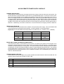
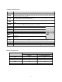
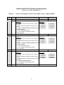
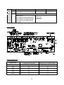
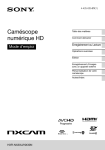
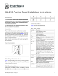
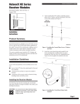
NX-320 REMOTE POWER SUPPLY
INSTALLATION MANUAL
TABLE OF CONTENTS
Page
General Description................................................................................................. 2
Installing the NX-320 ............................................................................................... 2
Enrolling the NX-320 ............................................................................................... 2
Understanding the LEDs ......................................................................................... 2
Terminal Descriptions.............................................................................................. 3
Programming the NX-320 ....................................................................................... 4
Programming Outputs A - C ..............................................................................4 - 6
Programming Codes 1 - 99 ...............................................................................6 - 7
Programming Worksheets ...............................................................................8 - 10
NX-320 Layout .......................................................................................................10
Specifications and Warranty..................................................................................12
1-800-727-2339
NX-320 REMOTE POWER SUPPLY MODULE
GENERAL DESCRIPTION
The NX-320 is a microprocessor controlled remote power supply module for the NX-8 control panel. The
NX-320 has three (3) programmable outputs and one (1) dedicated bell output. A maximum of four (4) NX320 power supply modules can be added to the NetworX control panel for a total output count of 16, of
which 12 are programmable and 4 are dedicated bell outputs. These 12 programmable outputs can be used
as auxiliary power, smoke detector power, siren driver power, etc. (see chart on page 4). Each NX-320 has
a Tamper terminal that can be used to supervise the metal enclosure. When the NX-320 is connected to
the NX-8 control panel, the maximum total wire run from the panel to all devices, including the NX-320, is
2500 feet. Additionally, the maximum total wire run from the NX-320 to all outgoing devices is 2500 feet.
INSTALLING THE NX-320
The first thing that must be decided is the address of this particular power supply. This is the address that
will be selected when programming the NX-320. To set the address, use the table below.
Dip Switch 4 is used to disable the Tamper feature of the NX-320 (“On = enabled / “Off” = disabled).
Address
Dip switch 1
Dip switch 2
Dip switch 3
84
OFF
OFF
NA
85
ON
OFF
NA
86
OFF
ON
NA
87
ON
ON
NA
ENROLLING THE NX-320 REMOTE POWER SUPPLY
The NX-8 has the ability to automatically find and store in its memory the presence of all keypads, zone
expanders, wireless receivers and any other module connected to the data terminal. This allows these
modules to be supervised by the control panel. To enroll the modules enter the Program Mode of the NX-8
control panel, and when the Program Mode is exited, it will automatically enroll the devices. The enrolling
process takes about 12 seconds, during which time the “Service” LED will illuminate. User codes will not be
accepted during the enrolling process. Once a module is enrolled, if it is not detected by the control, the
“Service” LED will illuminate.
UNDERSTANDING THE LEDS
The NX-320 has four (4) red LEDs, which provide valuable information about the status of the NX-320. The
following chart furnishes the indications of each LED.
LED
Description
DS1
Flashes when data is transmitted out from the NX-320.
DS2
Flashes when data is transmitted into the NX-320.
DS3
Flashes during normal operation.
DS4
Used for hardware, and will only glow dimly when connected to the NX-8 control panel.
2
TERMINAL DESCRIPTIONS
Terminal
Description
DATA
Connect to the NX-8 control panel Data terminal. This terminal is the incoming data-signaling
terminal to the NX-320. The maximum total wire run from the control panel to all devices,
including the NX-320, is 2500 feet.
COM
Connect to the NX-8 control panel COMMON terminal. This terminal supplies the common
side of the power to the NX-320 board.
POS
Connect to control panel AUX POWER + terminal. This terminal supplies power to the NX-320
board.
DATA
This terminal is the outgoing data-signaling terminal for buss extension. The maximum total
wire run from the NX-320 to all outgoing devices is 2500 feet.
COM
Common terminal for any device powered from the NX-320.
OUT A
Programmable output current limited to 1.5 Amps.
OUT B
Programmable output current limited to 1.5 Amps.
Common terminal for any device powered from the NX-320.
COM
OUT C
BELL +
BELL TAM
EARTH
NOTE: The total
current of the
NX-320 is 2.0
Positive of bell output current limited to 2.5 Amps. Connect as in diagram
Amps.
on page 10.
Programmable output current limited to 1.5 Amps.
Negative of bell output current limited to 2.5 Amps. Connect as in diagram
on page 10.
This is an optional tamper terminal. To use this feature, connect the normally closed tamper
switch between this terminal and COM. If switch 4 is off, this feature is not used.
Earth Ground.
AC
AC Input. Connect to a 16.5V 25, 40, or 50 VA Class II UL approved transformer.
AC
AC Input. Connect to a 16.5V 25, 40, or 50 VA Class II UL approved transformer.
WIRING REQUIREMENTS
LENGTH
WIRE GAUGE
(MEASURED IN FEET)
WHEN CONNECTED
TO NX-8
WHEN CONNECTED
TO ANOTHER NX-320
400
24
24
500
24
22
1000
24
20
2000
22
18
2500
20
16
3
PROGRAMMING THE NX-320
The Program Mode is accessed by entering [rr]-[8] (all of the function key LEDs will begin to flash). Enter
the "Go To Program" code (default is [9]-[7]-[1]-[3]). If the code was valid, the Service LED will flash, and
the function LEDs will illuminate steady, indicating the device to program should be entered. Next, enter the
address of the NX-320 (see chart on page 2) followed by [#]. At this point, the Armed LED will illuminate
while it is waiting for a programming location to be entered. Enter the desired programming location. The
Armed LED will begin to flash while a programming location is being entered. Enter the [#] key. If this is a
valid location, the Armed LED will extinguish, the Ready LED will illuminate, and the binary data for the first
segment of this location will be shown on the zone LEDS. To change the data, enter the data followed by
[rr]. The data will be entered, and the location will automatically increment to the next segment. The data
for that segment will be displayed. This procedure is repeated until the last segment is reached. Pressing
the [#] key will exit from this location. To review the data, repeat the above procedure, pressing the [rr] key
without entering data first. Each time the [rr] key is pressed, the next segment is displayed. Programming
data is always one of two types of data. The first type is numerical, and can take on values from 0-255 or
0-15 depending on the segment size. The second type is a feature selection type. Feature selection data
is used to turn features on or off. LCD Keypad Users Note: All steps required for programming are the
same as the aforementioned LED keypad. The LCD keypad display will prompt you for the data required.
While in the programming mode, and not in a location, the number in parenthesis is the location you were
previously changing. For example, if the display reads "Enter location, then # (5)", it is reminding you that
location 5 was the last location you programmed. In feature selection data, the numbers of the enabled
features will be displayed. However, the features not enabled will display a hyphen (-).
LOCATION 0
PROGRAMMING THE EVENT & TIME FOR OUTPUT A (1 segment of numerical data)
Segment 1 is used to select the particular event that will trigger Output A. See following chart for the
specific events that can be selected.
Segment 2 is used to select the amount of time an output will remain activated when an output triggers.
If this location is programmed as a zero, the output will follow the particular event.
#
0
1
Event
Always On
AC Fail (control or exp.) Does
not follow AC Fail delay time
#
11
Event
Smoke Power Reset
#
22
Event
Disarmed
12
Yelping Siren
23
Ready to Arm
2
Low Battery (control or exp.)
13
Steady Siren
24
Not Ready to Arm
3
Dynamic Battery Test Time
14
Any Siren
25
Fire
4
Listen In
15
Steady Siren (temporal)
26
Fire Trouble
5
Line Seizure
16
Any Siren (temporal)
27
Chime
6
Telephone Line Fault
17
Alarm Memory
28
Beeping Keypad
7
Program Mode
18
Entry
29F
F Aux 1 Keypad Function
8
Over-current (control or exp.)
19
Exit
30F
F Aux 2 Keypad Function
9
Box Tamper (control or exp.)
20
Entry or Exit
10
Siren Tamper (control or exp.)
21
Armed
31F
F Panic Keypad Function
Code Entry (set codes in loc
32F
F
8 – 17)
F If set to follow condition, these events will be one second.
4
LOCATION 1
data)
PROGRAMMING SPECIAL FEATURES FOR OUTPUT A (8 segments of feature selection
Segment 1 selects the following special conditions:
1=
2=
3=
4=
5=
6=
7=
8=
"On" if output should time in minutes; "Off" if output times in seconds.
"On" if output should latch until a code is entered; “Off” for timed.
"On" if output should stop time when a code is entered.
“On” for inverted output.
“On” disables output during listen-in (only events 12-16).
Reserved.
Reserved.
Reserved.
Segment 2 selects the following partitions:
1
2
3
4
5
6
7
8
=
=
=
=
=
=
=
=
"On" if the event should activate when it occurs in Partition 1.
"On" if the event should activate when it occurs in Partition 2.
"On" if the event should activate when it occurs in Partition 3.
"On" if the event should activate when it occurs in Partition 4.
"On" if the event should activate when it occurs in Partition 5.
"On" if the event should activate when it occurs in Partition 6.
"On" if the event should activate when it occurs in Partition 7.
"On" if the event should activate when it occurs in Partition 8.
LOCATION 2
PROGRAMMING THE EVENT & TIME FOR OUTPUT B (1 segment of numerical data)
Segment 1 is used to program the particular event that will trigger Output B. See chart on page 4 for the
specific events that can be selected.
Segment 2 is used to select the amount of time an output will remain activated when an output triggers. If
this location is programmed as a zero, the output will follow the particular event.
LOCATION 3
data)
PROGRAMMING SPECIAL FEATURES FOR OUTPUT B (8 segments of feature selection
Segment 1 selects the following special conditions:
1
2
3
4
5
6
7
8
=
=
=
=
=
=
=
=
"On" if output should time in minutes; "Off" if output times in seconds.
"On" if output should latch until a code is entered; “Off” for timed.
"On" if output should stop time when a code is entered.
"On" for inverted output.
“On” disables output during listen-in (only events 12-16).
Reserved.
Reserved.
Reserved.
Segment 2 selects the following partitions:
1
2
3
4
5
6
7
8
=
=
=
=
=
=
=
=
"On" if the event should activate when it occurs in Partition 1.
"On" if the event should activate when it occurs in Partition 2.
"On" if the event should activate when it occurs in Partition 3.
"On" if the event should activate when it occurs in Partition 4.
"On" if the event should activate when it occurs in Partition 5.
"On" if the event should activate when it occurs in Partition 6.
"On" if the event should activate when it occurs in Partition 7.
"On" if the event should activate when it occurs in Partition 8.
5
LOCATION 4
PROGRAMMING THE EVENT & TIME FOR OUTPUT C (1 segment of numerical data)
Segment 1 is used to program the particular event that will trigger Output C. See chart on page 4 for the
specific events that can be selected.
Segment 2 is used to select the amount of time an output will remain activated when an output triggers. If
this location is programmed as a zero, the output will follow the particular event.
LOCATION 5
data)
PROGRAMMING SPECIAL FEATURES FOR OUTPUT C (8 segments of feature selection
Segment 1 selects the following special conditions:
1
2
3
4
5
6
7
8
=
=
=
=
=
=
=
=
"On" if output should time in minutes; "Off" if output times in seconds.
"On" if output should latch until a code is entered; “Off” for timed.
"On" if output should stop time when a code is entered.
"On" for inverted output.
“On” disables output during listen-in (only events 12-16).
Reserved.
Reserved.
Reserved.
Segment 2 selects the following partitions:
1
2
3
4
5
6
7
8
=
=
=
=
=
=
=
=
"On" if the event should activate when it occurs in Partition 1.
"On" if the event should activate when it occurs in Partition 2.
"On" if the event should activate when it occurs in Partition 3.
"On" if the event should activate when it occurs in Partition 4.
"On" if the event should activate when it occurs in Partition 5.
"On" if the event should activate when it occurs in Partition 6.
"On" if the event should activate when it occurs in Partition 7.
"On" if the event should activate when it occurs in Partition 8.
LOCATIONS 6 & 7
RESERVED
LOCATION 8
CODES 1-10 OUTPUT ENABLE (10 segments of feature selection data)
When activating outputs with a user code (event #30), location 8 can be used to restrict certain codes from
activating certain outputs. Location 8 contains 10 segments. Segment 1 corresponds to user 1; Segment
10 corresponds to user 10. The LEDs correspond to outputs A - C.
LED
DESCRIPTION
1
"On" if code will activate Output A; "Off" if it will not.
2
"On" if code will activate Output B; "Off" if it will not.
3
"On" if code will activate Output C; "Off" if it will not.
Reserved.
4
LOCATION 9
CODES 11-20 OUTPUT ENABLE (10 segments of feature selection data)
When activating outputs with a user code (event #30), location 9 can be used to restrict certain codes from
activating certain outputs. Location 9 contains 10 segments. Segment 1 corresponds to user 11; Segment
10 corresponds to user 20. The LEDs correspond to outputs A - C (see chart above).
LOCATION 10
CODES 21-30 OUTPUT ENABLE (10 segments of feature selection data)
When activating outputs with a user code (event #30), location 10 can be used to restrict certain codes from
activating certain outputs. Location 10 contains 10 segments. Segment 1 corresponds to user 21; Segment
10 corresponds to user 30. The LEDs correspond to outputs A - C (see chart above).
6
LOCATION 11
CODES 31-40 OUTPUT ENABLE (10 segments of feature selection data)
When activating outputs with a user code (event #30), location 11 can be used to restrict certain codes from
activating certain outputs. Location 11 contains 10 segments. Segment 1 corresponds to user 31; Segment
10 corresponds to user 40. The LEDs correspond to outputs A - C (see chart above).
LOCATION 12
CODES 41-50 OUTPUT ENABLE (10 segments of feature selection data)
When activating outputs with a user code (event #30), location 12 can be used to restrict certain codes from
activating certain outputs. Location 12 contains 10 segments. Segment 1 corresponds to user 41; Segment
10 corresponds to user 50. The LEDs correspond to outputs A - C (see chart above).
LOCATION 13
CODES 51-60 OUTPUT ENABLE (10 segments of feature selection data)
When activating outputs with a user code (event #30), location 13 can be used to restrict certain codes from
activating certain outputs. Location 13 contains 10 segments. Segment 1 corresponds to user 51; Segment
10 corresponds to user 60. The LEDs correspond to outputs A - C (see chart above).
LOCATION 14
CODES 61-70 OUTPUT ENABLE (10 segments of feature selection data)
When activating outputs with a user code (event #30), location 14 can be used to restrict certain codes from
activating certain outputs. Location 14 contains 10 segments. Segment 1 corresponds to user 61; Segment
10 corresponds to user 70. The LEDs correspond to outputs A - C (see chart above).
LOCATION 15
CODES 71-80 OUTPUT ENABLE (10 segments of feature selection data)
When activating outputs with a user code (event #30), location 15 can be used to restrict certain codes from
activating certain outputs. Location 15 contains 10 segments. Segment 1 corresponds to user 71; Segment
10 corresponds to user 80. The LEDs correspond to outputs A – C (see chart on page 6).
LOCATION 16
CODES 81-90 OUTPUT ENABLE (10 segments of feature selection data)
When activating outputs with a user code (event #30), location 16 can be used to restrict certain codes from
activating certain outputs. Location 16 contains 10 segments. Segment 1 corresponds to user 81; Segment
10 corresponds to user 90. The LEDs correspond to outputs A - C (see chart on page 6).
LOCATION 17
CODES 91-99 OUTPUT ENABLE (9 segments of feature selection data)
When activating outputs with a user code (event #30), location 17 can be used to restrict certain codes from
activating certain outputs. Location 17 contains 9 segments. Segment 1 corresponds to user 91; Segment
9 corresponds to user 99. The LEDs correspond to outputs A - C (see chart on page 6).
LOCATION 18
A/C DELAY AND DYNAMIC BATTERY TEST (2 segments of feature selection data)
Location 18 is used to enable the A/C delay and the Dynamic Battery Test, both of which are timed in
minutes. The factory default is 5-0, meaning the A/C power will be off for 5 minutes before a report is sent
or a Service light will illuminate, and the Dynamic Battery Test is disabled (“0” minutes). If you desire the
A/C delay to be 8 minutes and the Dynamic Battery Test to be 3 minutes, you would program [8]-[3].
LOCATION 19
DEVICE OPTIONS (8 segments of feature selection data)
Location 19 is used to enable various system features of the NX-320 power supply.
LED
1
2
3
4
5-8
Description
On for AC report always sent; Off follows control
§ If enabled, an AC Fail report will be sent if power is lost for the time programmed in
Location 18. If “off”, the report will only be sent if the control panel has not sent an AC
Power Lost report, and AC Fail report is enabled in Location 37.
On enables periodic Battery Test
§ Enables Battery Missing every 30 seconds.
On enables Low Battery reporting
§ If enabled, the NX-320 will report Low Battery to the central station.
On enables Siren Tamper/Trouble reporting
§ If enabled, the NX-320 will report a Siren Tamper to the central station.
Reserved
7
NetworX NX-320 Programming Worksheets
(Defaults are printed in bold italics text.)
At Default:
Output A = AUX POWER, Output B = AUX POWER, Output C = SMOKE POWER
LOC
PAGE
DESCRIPTION
DEFAULT
DATA
0
1
4
5
OUTPUT A EVENT & TIME
OUTPUT A SPECIAL FEATURES
Segment 1
1 = "On" if timed in minutes; "Off" if timed in
seconds.
2 = "On" if latched until code is entered; “Off” for
timed.
3 = "On" if output should stop time when a
code is entered.
4 = "On" for inverted output.
5 = “On” disables output during listen-in.
6-8 = Reserved
0 10
_ _
2
4
3
5
4
6
5
6
6&7
6
OUTPUT B EVENT & TIME
OUTPUT B SPECIAL FEATURES
Segment 1
1 = "On" if timed in minutes; "Off" if timed in
seconds.
2 = "On" if latched until code is entered; “Off” for
timed.
3 = "On" if output should stop time when a
code is entered.
4 = "On" for inverted output.
5 = “On” disables output during listen-in.
6-8 = Reserved.
OUTPUT C EVENT & TIME
OUTPUT C SPECIAL FEATURES
Segment 1
1 = "On" if timed in minutes; "Off" if timed in
seconds.
2 = "On" if latched until code is entered; “Off” for
timed.
3 = "On" if output should stop time when a code
is entered.
4 = "On" for inverted output.
5 = “On disables output during listen-in.
6-8 = Reserved.
RESERVED.
8
Segment 2
1 = Partition 1
2 = Partition 2
3 = Partition 3
4 = Partition 4
0 10
Segment 2
1 = Partition 1
2 = Partition 2
3 = Partition 3
4 = Partition 4
11 8
Segment 2
1 = Partition 1
2 = Partition 2
3 = Partition 3
4 = Partition 4
5 = Partition 5
6 = Partition 6
7 = Partition 7
8 = Partition 8
_ _
5 = Partition 5
6 = Partition 6
7 = Partition 7
8 = Partition 8
_ _
5 = Partition 5
6 = Partition 6
7 = Partition 7
8 = Partition 8
LOC
8
9
10
11
12
13
14
15
16
17
PAGE
6
6
6
7
7
7
7
7
7
7
DESCRIPTION
Codes 1-10 Output Enable (Circle the numbers to program)
User
1
2
3
4
5
6
7
Output #A
1
1
1
1
1
1
1
Output #B
2
2
2
2
2
2
2
Output #C
3
3
3
3
3
3
3
Codes 11-20 Output Enable (Circle the numbers to program)
User
11
12
13
14
15
16
17
Output #A
1
1
1
1
1
1
1
Output #B
2
2
2
2
2
2
2
Output #C
3
3
3
3
3
3
3
Codes 21-30 Output Enable (Circle the numbers to program)
User
21
22
23
24
25
26
27
Output #A
1
1
1
1
1
1
1
Output #B
2
2
2
2
2
2
2
Output #C
3
3
3
3
3
3
3
Codes 31-40 Output Enable (Circle the numbers to program)
User
31
32
33
34
35
36
37
Output #A
1
1
1
1
1
1
1
Output #B
2
2
2
2
2
2
2
Output #C
3
3
3
3
3
3
3
Codes 41-50 Output Enable (Circle the numbers to program)
User
41
42
43
44
45
46
47
Output #A
1
1
1
1
1
1
1
Output #B
2
2
2
2
2
2
2
Output #C
3
3
3
3
3
3
3
Codes 51-60 Output Enable (Circle the numbers to program)
User
51
52
53
54
55
56
57
Output #A
1
1
1
1
1
1
1
Output #B
2
2
2
2
2
2
2
Output #C
3
3
3
3
3
3
3
Codes 61-70 Output Enable (Circle the numbers to program)
User
61
62
63
64
65
66
67
Output #A
1
1
1
1
1
1
1
Output #B
2
2
2
2
2
2
2
Output #C
3
3
3
3
3
3
3
Codes 71-80 Output Enable (Circle the numbers to program)
User
71
72
73
74
75
76
77
Output #A
1
1
1
1
1
1
1
Output #B
2
2
2
2
2
2
2
Output #C
3
3
3
3
3
3
3
Codes 81-90 Output Enable (Circle the numbers to program)
User
81
82
83
84
85
86
87
Output #A
1
1
1
1
1
1
1
Output #B
2
2
2
2
2
2
2
Output #C
3
3
3
3
3
3
3
Codes 91-99 Output Enable (Circle the numbers to program)
User
91
92
93
94
95
96
97
Output #A
1
1
1
1
1
1
1
Output #B
2
2
2
2
2
2
2
Output #C
3
3
3
3
3
3
3
9
8
1
2
3
9
1
2
3
10
1
2
3
18
1
2
3
19
1
2
3
20
1
2
3
28
1
2
3
29
1
2
3
30
1
2
3
38
1
2
3
39
1
2
3
40
1
2
3
48
1
2
3
49
1
2
3
50
1
2
3
58
1
2
3
59
1
2
3
60
1
2
3
68
1
2
3
69
1
2
3
70
1
2
3
78
1
2
3
79
1
2
3
80
1
2
3
88
1
2
3
89
1
2
3
90
1
2
3
98
1
2
3
99
1
2
3
LOC
18
PAGE
7
19
7
DESCRIPTION
DEFAULT
A/C Delay (in minutes)
5
Dynamic Battery Test (in minutes)
0
Device Options (Circle the numbers to program)
1=On for AC report always sent; Off
5=Reserved
follows control
6=Reserved
2=On enables periodic battery test
7=Reserved
3=On enables low battery reporting
8=Reserved
4=On enables siren tamper/trouble
reporting
DATA
___
___
NX-320 LAYOUT
MAXIMUM WIRE RUNS
Length in Feet
Wire Gauge
From NX-8 Control Panel
Wire Gauge
Daisy Chain to another NX-320
400
24
24
500
24
22
1000
24
20
2000
22
18
2500
20
16
10
ENCLOSURE DIAGRAM
Inside the can, several 2-holed insertion points have been constructed.
This allows for either vertical or horizontal placement of the modules.
Notice that the insertion points have two sizes of holes -- a larger
hole and a smaller hole.
Diagram 1: The black plastic PCB guides are grooved on one edge
where the PC Board will be seated. The end with the half-moon protrusion
fits into the larger hole. The smaller hole is for the screw.
Diagram 2: Place the first black plastic PCB guide in the top insertion
point, grooved edge downward. The half-moon protrusion will be in the
large hole. It does not require force. Insert one of the provided screws
into the smaller hole (from inside the can) to secure it in place. A
screwdriver should reach through the notch that runs the length of the
guide to tighten the screw. The second PCB guide should be positioned
opposite of the first (grooved edge up) and placed in the lower insertion
point, using the same procedures described above. Once mounted, screw
it in securely.
Diagram 3: The PC board should slide freely in the grooves of both
guides.
SYSTEM NOTES
11
SPECIFICATIONS
NX-320 DIMENSIONS
2” Wide
9” High
4” Deep
CURRENT DRAW
10 mA Standby
16.5 VAC 40 or 50 VA Transformer
AUXILIARY POWER
Limited to 2.0 Amps with 50 VA
Limited to 1.5 Amps with 40 VA
OPERATING TEMPERATURE
32 to 120 degrees F
SHIPPING WEIGHT
8 lbs.
FIVE YEAR LIMITED WARRANTY
CADDX CONTROLS, INC. GUARANTEES THIS PRODUCT AGAINST DEFECTIVE PARTS AND
WORKMANSHIP FOR TWENTY-FOUR (24) MONTHS FROM DATE OF MANUFACTURING. IF ANY
DEFECT APPEARS DURING THE WARRANTY PERIOD, RETURN IT TO CADDX, POSTAGE PREPAID.
THE UNIT WILL BE REPAIRED AND RETURNED WITHOUT CHARGE.
FOR THE REMAINING 36 MONTHS OF WARRANTY, THE CHARGE TO REPAIR OR REPLACE THIS
MODULE WILL NOT EXCEED $10.00 PLUS SHIPPING AND HANDLING.
CADDX ASSUMES NO LIABILITY FOR CONSEQUENTIAL OR INDIRECT DAMAGE AND ACCEPTS NO
RESPONSIBILITY FOR REPAIRING DAMAGE TO THE PRODUCT CAUSED BY MISUSE, CARELESS
HANDLING, OR WHERE REPAIRS HAVE BEEN MADE BY OTHERS.
NO OTHER GUARANTEE, WRITTEN OR VERBAL, IS AUTHORIZED BY OR ON BEHALF OF CADDX
CONTROLS, INC., GLADEWATER, TEXAS.
CADDX CONTROLS, INC.
1420 NORTH MAIN STREET
GLADEWATER, TEXAS 75647
TOLL FREE 800-727-2339
FAX 903-845-6811
www.caddx.com
NX-320 INSTALLATION MANUAL
NX320IB98 REV B (9-20-98)