1
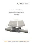
Brief Installation Manual GTTS-2000B V1.3
GTTS-2000B Iridium Global Tracking & Tracing System
Prior to mechanical installation the GTTS unit shall be activated in the Iridium Satellite Network.
Send an email to [email protected] with a list of IMEI numbers from the units that needs to be
activated. Only activation requests from authorized dealers will be processed. The IMEI numbers can be
found on 2 different barcode labels on the bottom of the unit and also on a barcode label on the carton
packing. IMEI nr. always starts with 300034………. or 300234………..
Activation is normally realized the same day during GTTSystems B.V. business hours.
Your subscription starts from this day.
The GTTS-2000B is very easy to install. It shall be installed in horizontal position onto a (ferro) steel surface
with no obstructions to the sky above.
As soon as the GTTS-2000B is mounted onto ferrous metal, it will be switched on automatically.
Make sure that bottom center touches steel. The ferro sensor is located at this position.
If the GTTS is provided with magnets, be aware. These magnets are very strong!!!
The GTTS-2000B will send a first GPS position immediately to confirm the unit is switched on and working
properly. Please note that it can take several minutes before a message from the unit is received (depending
on satellites in sight). GPS takes typically 40..50 seconds for a cold start fix.
Latency in the Iridium Network is very low. Typical values measured 12 .. 15 seconds
When the GTTS-2000B is removed from ferrous metal, it will be triggered to send a ‘sabotage message’. As
soon as the ‘sabotage message’ is sent, the GTTS-2000B will switch into the power-down state again
(factory power-down state).
When not in power-down mode, the GTTS-2000B will send a battery status message every 10080 minutes
(1 week).
The complete Installation and User’s manual can be found on http://www.gtts.eu/products.php in pdf format.
Installation with magnet mounting
Holding the GTTS-2000B with both hands, hold it over the area where it shall be placed. Tilt the GTTS2000B appr. 45 degrees as shown in figure 3 below. Then lower it onto the steel surface and turn the GTTS2000B until the magnets make contact with the steel surface. Try to do this as controlled as possible to avoid
a ‘slam’ and keep your fingers free from the GTTS-2000B surface contact area. Slamming the unit onto the
steel surface could cause damage due to extreme G-forces that might occur.
Reverse this procedure to remove an unit.
Never try to slide a unit. This will damage the magnetic’s corrosion protective coating and the steel (paint)
surface it is mounted on.
GTTSystems B.V. Herfordstraat 16 7418 EX Deventer T 0570 605075 F 0570 677755 E [email protected] W www.gtts.eu
2.3.2 Installation with screw mounting
If the GTTS-2000B should be installed using 4 pieces M5 bolts, the bolts shall not be longer then 18mm plus
the steel surface thickness.
Drill 4 holes Ø 5,5 mm according the drill plan. See figure below
X is steel surface thickness
Bolt M5 maximum length is X+18 mm
Make sure that bottom center touches steel. The ferro sensor is located at this position.