1
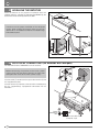
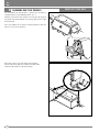
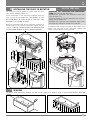
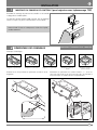
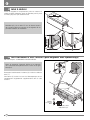
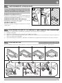
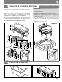
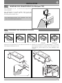
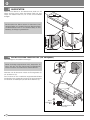
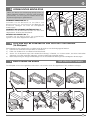
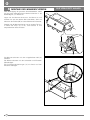
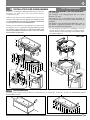
INSTALLATION MANUAL FOR BATHTUBS
MANUEL D’INSTALLATION DES BAIGNOIRES
HANDBUCH FÜR DIE INSTALLATION
GB
IMPORTANT: Before installing the bathtub, read this manual carefully.
Keep it for future reference together with the other documents.
This manual contains assembly instructions for bathtubs with and without whirlpool.
IMPORTANT
STANDARDS:
Teuco whirlpool bathtubs are manufactured and tested in accordance with European standards to guarantee maximum user safety.
HANDLING THE BATHTUB:
When removing the tub from its packaging and handling it in general, lift it by grasping the edges or the frame.
CHECKS:
After removing the bathtub from its packaging, check for any damage or defects.
ONCE THE UNIT HAS BEEN INSTALLED, THE WARRANTY NO LONG COVERS DAMAGE CAUSED BY BUMPS OR
ABRASIONS.
Make sure that plumbing and electrical connectors correspond to those indicated on the pre-installation chart.
The product must be installed against finished walls and floor.
All Teuco products are tested, approved and packaged on the company premises before shipping. Any water in the
bathtub is a result of test procedures. However, before proceeding with installation where masonry work is required,
check the system again, as described in the section "OPERATING TESTS", making sure that the unit functions
properly.
In the event of malfunction, contact a qualified Teuco service centre.
The company will not be liable for any damage caused by improper use.
The data and specifications given are not binding on Teuco Guzzini Spa, which reserves
the right to carry out any changes deemed appropriate without prior notice or obligation to update.
RULES ON INSTALLATION (for bathtubs with whirlpool)
See INSTALLATION STANDARDS manual attached.
2
GB
INSTALLATION GUIDE
1
MOUNTING THE CONTROL PANEL (for bathtubs with whirlpool TOP)
Mount the control panel onto the edge of the bathtub using the
pre-drilled hole.
Since the control panel can be rotated up to about 90°, make
sure that it is positioned at the right angle when being fastened
in place.
Tighten the nut firmly and lock it in place with a threadlocking liquid.
2
DISASSEMBLING THE PANELS
PANELLED TUBS ONLY
Examples of Panel Types:
Bathtub panelled
on 3 sides
Bathtub with 2 panels
Bathtub with 2 panels
Bathtub with front panel
Corner bathtub with
front panel
Remove the screws (Z) that secure the panels to the bath- Disassemble the panels in the following order: 1, 2, 3,
grasping them at the bottom and pulling them outwards to
tub frame.
release the clips (Y).
3
GB
3
LEVELLING THE BATHTUB
Place the bathtub in the prepared installation area and
proceed to level it, adjusting the perimeter feet followed by the
central feet until all are firmly level on the floor.
In order to ensure proper ventilation of the whirlpool
system, when making adjustments leave a minimum
distance of 15 mm between the floor and the bottom edge
of the bathtub panel.
4
ELECTRICAL CONNECTIONS (for bathtubs with whirlpool)
See INSTALLATION STANDARDS manual attached.
Before connecting the product to the mains power
supply, check that the ratings given on the data plate
correspond with those of the mains power supply.
Use the cable (T) to connect the taps to the terminal (S) for
the equipotential node.
Use the terminal (S) located at the base of the electropump
for the supplementary equipotential connection for the
bathroom.
Brown
Yellow/Green
Blue
Connection box with wire
clamp PG 13,5.
4
GB
5
PLUMBING CONNECTIONS
In the event of extremely hard mains water, it is
recommended that a water-conditioning unit be installed
to safeguard proper functioning of the whirlpool system.
a
b
c
BATHTUB WITH FILLER TAPS (Fig. a)
Connect the taps to the hot and cold water supplies. (see
enclosed instructions for tap assembly).
BATHTUB WITH COMBINED OVERFLOW AND FILLER SPOUT
(Fig. b)
Connect the mixer hose to the filler spout on the overflow.
BATH WASTE CONNECTION (Fig. c)
Connect the bath waste using the siphon supplied.
6
OPERATING AND WATERTIGHT TEST (for bathtubs with whirlpool)
On completion of plumbing and electrical connections, proceed as follows to test the system:
1) Clean the bathtub thoroughly.
2) Fill the bathtub to the overflow level.
3) Start the whirlpool system on and check to make sure there are no leaks.
4) Having completed these steps, proceed with the installation of the bathtub.
7
FIXING THE TUB TO THE FLOOR
PANELLED TUBS ONLY
Fix the tub to the floor by securing the feet as indicated in the illustration, using the screws and plugs provided.
Bathtub panelled on three sides
Bathtub with two panels
Bathtub with one panel
Corner Bathtub
5
GB
8
ASSEMBLING THE PANELS
PANELLED TUBS ONLY
On completion of connections, replace the previously
removed panels in the following order: 3, 2, 1.
Position the panel to the bathtub and clip the top edge of
the panel into place between the springs (M) and the edge
of the bathtub.
Press the bottom of the panel in correspondence with the
clips (Y) until it fits into place.
Raise the panels using the wedge (A) provided.
Secure the panels with the screws and collars (B).
Snap the concealers (C) onto the collars.
B
C
A
6
GB
9
BUILT-IN TUBS ONLY
INSTALLING THE BUILT-IN BATHTUB
To install the bathtub, follow the above steps and then
carry out the following procedures.
Place the bathtub in the prepared installation area and
level it using the adjustable feet. THE WEIGHT OF THE
BATHTUB MUST BE SUPPORTED BY THE FEET AND
NEVER BY THE PERIMETER EDGE.
Build the perimeter wall so that internally it extends a
maximum of 15 mm under the perimeter edge of the tub.
THIS IS TO ALLOW THE BATHTUB TO BE REMOVED FOR
FUTURE MAINTENANCE WITHOUT BEING DAMAGED.
MOUNTING THE INSPECTION AND VENTILATION
PANEL (for bathtubs with whirlpool)
Separate the inspection and ventilation panel (D)
from its frame (T).
Insert the frame (T) into the perimeter wall near the
pump and the power unit.
Remount the inspection and ventilation panel onto
the frame (T) and fasten it with the screws (Z).
In order to enable maintenance work on the bathtub, disassembly and inspection of the connection between the
siphon and bath waste must be possible.
550 50
ART.554
16
00
10
SEALING
To prevent water penetrating between the wall and the edge of the bathtub, apply a bead of NON-ACETIC, NEUTRAL
silicone.
7
F
IMPORTANT : Lisez la notice avant de procéder à l’installation de la baignoire
et mettez-la de côté avec les autres documents.
Ce manuel est valable pour le montage des baignoires avec et sans hydromassage.
CONSEILS
NORMATIVE :
Les baignoires d’hydromassage Teuco sont réalisé et testé conformément aux normes Européennes pour garantir un
maximum de sécurité à l’utilisateur.
MANUTENTION DE LA BAIGNOIRE :
Pour sortir la baignoire de son emballage et pour la déplacer, soulevez-la en la saisissant par le bord ou par son châssis.
NE SOULEVEZ JAMAIS LA BAIGNOIRE EN LA SAISISSANT PAR LES TUYAUX.
CONTRÔLES :
Après avoir déballé la baignoire, contrôlez qu’il n’y ait pas de défauts éventuels.
UNE FOIS QUE L’INSTALLATION A ÉTÉ EFFECTUÉE, LA GARANTIE N’EST PLUS APPLICABLE EN CAS DE DOMMAGES DUS À
DES CHOCS OU À DES ABRASIONS.
Vérifiez si les raccordements hydrauliques et électriques correspondent bien à ceux qui sont indiqués dans la fiche de préinstallation.
Procédez à l’installation une fois le plancher et les parois terminés.
Tous nos articles sont testés, contrôlés et emballés dans notre établissement. Suite au test, il se peut qu’il reste de l’eau à l’intérieur de
la baignoire; toutefois, avant de procéder à l’installation définitive de la baignoire par des travaux de maçonnerie, effectuez un essai
supplémentaire comme décrit dans la procédure “ESSAI DE FONCTIONNEMENT” pour vérifier le bon fonctionnement de l’appareil.
En cas de panne ou de mauvais fonctionnement de l’installation, faites appel à un technicien qualifié Teuco.
Notre Maison ne répond pas des dommages provoqués par des interventions non appropriées sur ses appareils.
Les données et les caractéristiques fournies par cette notice n’engagent aucunement Teuco Guzzini S.p.A. qui se réserve le droit d’apporter toutes les modifications qu’elle jugera nécessaires sans aucun préavis ni remplacement.
MODE D’INSTALLATION (pour baignoires avec hydromassage)
Voir manuel joint : CONSIGNES D’INSTALLATION.
8
F
INSTALLATION
1
MONTAGE DU PANNEAU DE CONTROLE (pour baignoires avec hydromassage TOP)
Procédez au montage du panneau de contrôle sur le bord de
la baignoire à l’endroit prévu.
Le panneau pouvant pivoter à 90° environ, lors du montage
veillez à ce que l’on puisse l’orienter dans le sens désiré.
Serrez à fond l’écrou en le bloquant à l’aide d’un liquide
antidesserrement.
2
UNIQUEMENT BAIGNOIRES AVEC PANNEAUX
DÉMONTAGE DES PANNEAUX
Exemples d’habillages
Baignoire à 3 panneaux
Baignoire à 2 panneaux
Baignoire à 2 panneaux
Enlevez les vis (Z) qui fixent les panneaux au châssis de la
baignoire.
Baignoire à panneau
frontal
Baignoire d’angle à
panneau frontal
Démontez les panneaux en suivant l’ordre 1, 2 , 3 en les
saisissant par le bas et en les tirant vers vous de manière à
ce que les clips (Y) sortent de leurs emplacements.
9
F
3
MISE À NIVEAU
Placez la baignoire à l’emplacement prévu et mettez-la à
niveau en réglant d’abord les pieds du périmètre puis les pieds
du milieu jusqu’à ce qu’ils touchent le sol.
Contrôlez qu’il y ait au moins 15 mm de distance entre le
sol et le bord inférieur du panneau de la baignoire afin de
permettre l’aération de l’installation.
4
RACCORDEMENTS ÉLECTRIQUES (pour baignoires avec hydromassage)
Voir manuel joint : CONSIGNES D’INSTALLATION.
Avant de connecter l’appareil, vérifiez si les données
de la plaquette correspondent bien à celles de la ligne
électrique.
Raccordez la robinetterie à la borne (S) à l’aide du câble de
terre (T).
Une borne (S) située à la base de l’électropompe sert au
raccordement équipotentiel supplémentaire dans la salle
de bains.
Marron
Jaune vert
Bleu
Boîtier avec serrecâble PG 13,5.
10
F
5
RACCORDEMENTS HYDRAULIQUES
Si l’eau de l’installation hydraulique est très dure, nous
conseillons l’installation d’un adoucisseur d’eau pour
garantir un bon fonctionnement de l’appareil.
a
b
c
BAIGNOIRES AVEC ROBINETTERIE (Fig.a)
Raccordez la robinetterie au réseau d’alimentation eau
chaude et eau froide (Pour le montage de la robinetterie,
consultez les instructions ci-jointes).
BAIGNOIRES AVEC DÉBIT PAR LE TROP-PLEIN (Fig.b)
Raccordez le tuyau de l’eau mitigée sur le raccord
correspondant de la colonne de vidage.
RACCORD DE VIDAGE (Fig.c)
Effectuez le raccord de vidage à l’endroit prévu à l’aide du
siphon fourni.
6
PROCÉDURE D’ESSAI ET D’ÉTANCHÉITÉ (pour baignoires avec hydromassage)
Une fois que les raccordements hydrauliques et électriques sont terminés, testez l’installation:
1) Nettoyez la baignoire.
2) Remplissez la baignoire jusqu’au trop-plein de la colonne de vidage.
3) Mettez en marche l’hydromassage (voir mode d’emploi) afin de vérifier qu’il n’y ait pas de fuites d’eau ou de signal de
panne sur le panneau de contrôle.
4) Après avoir effectué ces opérations, procédez à l’installation de la baignoire comme décrit dans les phases suivantes.
7
FIXATION AU SOL
UNIQUEMENT BAIGNOIRES AVEC PANNEAUX
Fixer la baignoire au sol sur les pieds indiqués sur le dessin, à l'aide des vis munies de chevilles d'arrêt fournies.
Baignoire trois panneaux
Baignoire deux panneaux
Baignoire un panneau
Baignoire d’angle
11
F
8
MONTAGE DES PANNEAUX
UNIQUEMENT BAIGNOIRES AVEC PANNEAUX
Après avoir effectué tous les raccordements, remontez les
panneaux enlevés auparavant en suivant l’ordre 3, 2, 1.
Appliquez le panneau contre la baignoire en appuyant sur
le bord supérieur du panneau de façon à ce qu’il aille se
glisser entre les ressorts (M) et le bord de la baignoire.
Appuyez dans le bas du panneau près des clips (Y) afin
que celles-ci entrent dans leurs sièges respectifs.
Soulevez les panneaux en utilisant le coin (A) fourni.
Fixez les panneaux à l'aide des vis et des cales (B).
Montez les bouchons (C) à pression sur les cales.
B
C
A
12
F
9
INSTALLATION DE LA BAIGNOIRE ENCASTRABLE UNIQUEMENT BAIGNOIRES ENCASTRABLES
Pour l’installation de la baignoire, respectez les indications
des phases précédentes et effectuez les opérations
suivantes.
Positionnez la baignoire à l’endroit voulu et mettez-la à
niveau en ajustant les pieds réglables; LA BAIGNOIRE
DOIT ÊTRE APPUYÉE AU SOL SUR LES PIEDS
RÉGLABLES ET NON PAS SUR SON PÉRIMÈTRE.
Réalisez le mur en maçonnerie 15 mm max. en retrait par rapport
au bord de la baignoire DE FAÇON À CE QUE, PAR LA SUITE, ON
PUISSE ENLEVER LA BAIGNOIRE POUR TOUTE OPÉRATION
DE MAINTENANCE SANS ENDOMMAGER LE MUR.
MONTAGE DU PANNEAU D’INSPECTION ET DE
VENTILATION (pour baignoires avec hydromassage)
Séparez le panneau d’inspection et de ventilation (D)
de son châssis (T).
Montez le châssis (T) sur le mur en maçonnerie à
proximité de la pompe et de l’unité de puissance.
Remontez le panneau d’inspection et de ventilation(D) sur le châssis (T),encastré au mur, en le fixant
à l’aide des vis (Z).
Les opérations d’entretien de la baignoire exigent que le
raccordement entre le siphon et le vidage au sol soit
démontable et inspectionnable.
550 50
ART.554
16
00
10
APPLICATION DE SILICONE
Pour éviter toute infiltration d’eau entre le mur et le bord de la baignoire, appliquez du silicone NEUTRE NON ACÉTIQUE.
13
D
WICHTIG: Lesen Sie dieses Handbuch vor der Installation der Wanne aufmerksam durch und
bewahren Sie es zusammen mit den übrigen Unterlagen auf.
Diese Anleitungen gelten für die Montage von Wannen mit sowie ohne Hydromassage.
HINWEISE
NORMEN:
Die TEUCO Whirlpools sind gemäß europäischen Normen für höchste Anwendersicherheit hergestellt und getestet.
HANDLING DER WANNE:
Heben Sie die Wanne bei Entfernen der Verpackung oder beim übrigen Handling NIEMALS AN DEN ROHRLEITUNGEN an,
sondern ausschließlich an den Rändern oder am Rahmen.
PRÜFUNGEN:
Überprüfen Sie die Wanne nach Abnahme der Verpackung auf eventuell vorhandene Schäden. DIE ERFOLGTE
INSTALLATION SCHLIESST DIE GARANTIE FÜR DURCH STÖSSE ODER REIBUNG VERURSACHTE SCHÄDEN AUS.
Überprüfen Sie, daß die hydraulischen und elektrischen Anschlüsse mit denen der Vorinstallationskarte übereinstimmen.
Bevor Sie die Wanne installieren, müssen Fußboden und Wände fertiggestellt sein.
Unsere gesamten Artikel werden in unserem Werk überprüft, inspiziert und verpackt. Eventuell vorhandene
Wasserrückstände sind auf diese Prüfungsphase zurückzuführen; bevor Sie jedoch eventuelle Mauerarbeiten für die
Installation der Wanne vornehmen, empfehlen wir, mittels einer weiteren Prüfung gemäß Abschnitt "PRÜFEN DER
FUNKTIONSWEISE" die ordnungsgemäße Betriebsweise zu kontrollieren.
Im Falle von Störungen oder schlechter Funktionsweise der Anlage wenden Sie sich bitte an das Teuco-Fachpersonal.
Die Firma haftet nicht für eventuelle Schäden, die durch unsachgemäße Behandlung der Anlage entstanden sind.
Die in diesem Handbuch angegebenen Daten und Eigenschaften sind für Teuco Guzzini S.p.A. nicht bindend; die Firma
behält sich das Recht vor, ohne Vorankündigung oder Ersatzleistungen, zweckmäßig erachtete Veränderungen vorzunehmen.
RICHTLINIEN ZUR INSTALLATION (für Whirlpools)
Siehe beiliegende INSTALLATIONSANLEITUNGEN.
14
D
INSTALLATION
1
MONTAGE DES SCHALTDISPLAY (für Whirlpools TOP)
Das Schaltdisplay an der
Stelle montieren.
am Wannenrand vorgesehenen
Das Schaltdisplay ist um 90˚ drehbar, daher ist bei der
Montage darauf zu achten, daß es in die gewünschte
Richtung gedreht werden kann.
Die Befestigungs-mutter fest anziehen
Gewindearretierflüssigkeit blockieren.
2
und
mit
ABNAHME DER WANNENSCHÜRZEN
NUR VERKLEIDETE WANNEN
Verkleidungsbeispiele
Wanne mit 3 Schürzen
Wanne mit 2 Schürzen
Wanne mit 2 Schürzen
Wanne mit
Frontschürze
Eckwanne mit
Frontschürze
Nehmen Sie die Schrauben (Z), mit denen die Schürzen am Nehmen Sie die Schürzen in der Reihenfolge 1, 2, 3 heraus,
Wannengestell befestigt sind, ab.
fassen Sie diese hierzu am unteren Teil an und ziehen Sie sie
so zu sich hin, daß die Clips (Y) aus ihren jeweiligen Sitzen
springen.
15
D
3
AUSRICHTEN
Stellen Sie die Wanne an der vorbestimmten Stelle auf und
richten Sie diese zuerst mittels der äußeren Füße und dann
mittels der mittleren Füße aus, bis sie fest auf dem Boden
aufliegen.
Bei Ausrichten der Wanne achten Sie bitte darauf, daß
zwischen Boden und unterem Rand der Wannenschürze
ein Mindestabstand von 15 mm bestehen bleibt, um eine
Belüftung der Anlage zu gewährleisten.
4
ELEKTRISCHER ANSCHLUSS (für Whirlpools)
Siehe beiliegende Installationsanleitungen.
Bevor die Anlage angeschlossen wird, überprüfen Sie
bitte, daß die auf dem Datenschild angegebenen
Daten mit denen des Stromnetzes übereinstimmen.
Verbinden Sie die Armaturen mittels des Erdungskabels (T)
mit der Klemme (S).
Zum Anschluß an den zusätzlichen äquipotentialen Knoten
des Badezimmers verwenden Sie bitten die entsprechende,
am Unterteil der Elektropumpe befindliche Klemme (S).
Braun
Gelb/Grün
Blau
Dose mit Kabelklemme
PG 13,5.
16
D
5
HYDRAULISCHE ANSCHLÜSSE
Sollte das Wasser der Versorgungsanlage einen zu
hohen Kalkgehalt aufweisen, raten wir, einen Enthärter
einzubauen, um eine gute Funktionsweise der
Hydromassageanlage zu gewährleisten.
a
b
c
WANNEN MIT ARMATUREN (Abb. a)
Schließen Sie die Armaturen an das Warm- und
Kaltwassernetz an. (Hinsichtlich der Montage der
Armaturen befolgen Sie bitte die beiliegenden
Anweisungen).
WANNEN MIT WASSERABGABE VOM ÜBERLAUF (Abb. b)
Verbinden Sie das Mischwasserrohr mit dem dazu
vorgesehenen Anschluß der Ablaufsäule.
ANSCHLUSS DES ABLAUFS (Abb. c)
Schließen Sie den Ablauf mittels des mitgelieferten
Syphons an der dafür vorgesehenen Stelle an.
6
PRÜFUNG DER BETRIEBSWEISE UND DICHTHEIT DER ANLAGE
(für Whirlpools)
Nach Herstellung der hydraulischen und elektrischen Anschlüsse muß die Anlage geprüft werden:
1) Entfernen Sie eventuelle Schmutzstellen an der Wanne.
2) Füllen Sie die Wanne bis zum Überlauf der Ablaufsäule.
3) Setzen Sie die Hydromassage (siehe Gebrauchsanleitung) in Betrieb, um sicherzustellen, daß keine Leckstellen
vorhanden sind, oder eventuelle Störungen auf dem Schaltdisplay angezeigt werden.
4) Nach Überprüfung der Anlage vervollständigen Sie die Installation der Wanne gemäß nachfolgender Anweisungen.
7
BEFESTIGUNG AM BODEN
NUR VERKLEIDETE WANNEN
Den Whirlpool anhand der mitgelieferten Schrauben und Scheiben durch die abgebildeten Füße am Boden befestigen.
Wanne mit 3 Schürzen
Wanne mit 2 Schürzen
Wanne mit 1 Schürze
Eckwanne
17
D
8
MONTAGE DER WANNENSCHÜRZEN
NUR VERKLEIDETE WANNEN
Nach Beendigung der gesamten Anschlußarbeiten setzen
Sie die zuvor abgenommenen Wannenschürzen in der
Reihenfolge 3, 2, 1 wieder ein.
Legen Sie die Wannenschürze an die Wanne an und
drücken Sie auf den oberen Rand derselben, damit sie
zwischen den Federn (M) und dem Wannenrand einrastet.
Drücken Sie die Wannenschürze nun am unteren Teil, d.h.
in Höhe der Clips (Y) so an, daß letztere in ihre
entsprechenden Sitze einrasten.
Die Wannenschürzen mit dem mitgelieferten Keil (A)
anheben.
Die Wannenschürzen mit den Schrauben und Einsätzen
(B) befestigen.
Die Schraubenabdeckungen (C) mit Druck auf den
Einsätzen anbringen.
B
C
A
18
D
9
NUR EINBAUWANNEN
INSTALLATION DER EINBAUWANNE
Führen Sie die folgenden Montageanweisungen durch und
beachten Sie dabei auch die zuvor beschriebenen
Installationsphasen.
Stellen Sie die Wanne an ihrem vorbestimmten Platz auf und
richten Sie diese mittels der dazu vorgesehenen Stellfüßchen eben
aus; DIE WANNE MUSS MIT DEN FÜSSCHEN AUF DEM BODEN
STEHEN UND NICHT MIT DEM WANNENRAND.
Errichten Sie die Außenwand, die gegenüber dem Wannenrand
um höchstens 15 mm zurückstehen soll, UND ZWAR SO, DASS
DIE WANNE FÜR EVENTUELLE WARTUNGSARBEITEN
HERAUSGENOMMEN WERDEN KANN, OHNE DIE WAND
BESCHÄDIGEN ZU MÜSSEN.
MONTAGE DER KONTROLL- UND LÜFTUNGSKLAPPE
(für Whirlpools)
Die Kontroll- und Lüftungsklappe (D) aus ihrem
Rahmen (T) lösen.
Den Rahmen (T) in die Außenmauer der Wand in
unmittelbarer Nähe der Pumpe und der Steuereinheit
einbauen.
Die Kontroll- und Lüftungsklappe (D) wieder in den in
die Mauer eingebauten Rahmen (T) einsetzen und
mit den Schrauben (Z) befestigen.
Um die Wartung der Wanne zu ermöglichen, muß der
Anschluß zwischen Siphon und Ablauf am Boden so vorgenommen werden, daß eine Demontage und Inspektion desselben jederzeit möglich ist.
550 50
ART.554
16
10
00
SILIKONIEREN
Um Wasserinfiltrationen zwischen Mauer und Wannenrand zu vermeiden, verwenden Sie bitte ein NEUTRALES NICHT
ESSIGSAURES Silikon.
19
Teuco Guzzini S.p.A.
Via Avogadro, 12 - Zona industriale Enrico Fermi - 62010 Montelupone (MC) - Italy
Tel.0733/2201 - Fax 0733/220391 - NUMERO VERDE 800-270270
United Kingdom: Teuco U.K.
Suite 314 - Business Design Centre - 52 Upper Street -London N 1 0QH
Tel. 020 77042190 - Fax 020 77049756
www.teuco.co.uk - E-mail: [email protected]
Deutschland: Teuco Deutschland GmbH
Industriestraße 161c - 50999 Köln-Rodenkirchen
Tel. 02236 74780 - Fax 02236 747829 - Freecall: 0800 100 8826
www.teuco.de - E-mail: [email protected]
67001634000 (2007.00)
France: Teuco France
Z.I.Les Algorithmes 141-145, Rue Michel Carré - 95100 Argenteuil
Téléphone (1)39615042 - Télécopie (1)39473940
www.teuco.fr
España: Teuco España s.l.
Pol. Ind. “Can Jardi” - c/Strauss s/n - 08191 Rubi (Barcelona)
Tel. (93) 6999162 - Fax (93) 5883253
www.teuco.es - E-mail: [email protected]
Russia: “TEUCO 000”
23, Novoslobodskaya Ul. - Meyerhol Centre - 127055 Moscow
E-mail: [email protected] - Internet: http://www.teuco.com