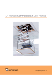
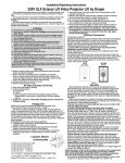
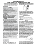
1
LP Morgan Auditorium Lift user manual
www.lpmorgan.com.au
LP Morgan Auditorium Lift Instructions
Table of contents
Hanging Unit
3
Electrical Connections
4
Operation
5-6
Installing Projector
7-8
Installing Optional
Projector Mount
9 - 10
Installing Optional
Ceiling Closure
11-12
Installing Optional
Ceiling Trim Kit
13
Connecting Controls
14 - 15
Clear Show Position
16
Auditorium Lift
Dimensions
18 - 19
CAUTION:
• Read instructions completely before proceeding.
• Unpack & Test lift prior to installation - ensure ALL packaging
material has been removed.
• Follow instructions carefully - Incorrect installation VOIDS WARRANTY.
• DO NOT obstruct operation of Scissor Lift, as serious injury or
damage may result.
• Test lift prior to installation
• Maximum lifting capacity is 159kg.
• Installed Lift MUST BE ‘levelled’
• Unit operates on 220V AC.
CAUTION:
Before servicing unit, disconnect hardwired control and any
remote control.
Note: Unit has been thoroughly inspected and tested at factory and
found to be operating correctly prior to shipment.
Information in this document is subject to
change without notice.
© Herma Technologies. All rights reserved.
This document is protected against
unauthorised copying electronic or otherwise.
Trademarks used in this text: Herma, the
Herma Logo, Galleria, LP Morgan and
2 | LP Morgan user manual
LP Morgan logo are registered trademarks of
Herma Technologies.
Other trademarks and trade names used in this
document remain the property
of the relevant owners.
October 2011 Version 1
LP Morgan Auditorium Lift Instructions
Hanging Unit
Note: If using Environmental Air Space Housing option, go to Environmental
Air Space Housing (instructions on page 3)
The Scissor Lift may be installed in a variety of ways; recessed above the
ceiling, or suspended below the ceiling. The lift should be supported by four
12.7 threaded mounting rods. If ceiling recessed, the entire unit (including
the projector) should set approximately 38mm above the finished ceiling
in its ‘stored’ position. The threaded rods should pass through the corner
mounting flanges and be secured by nuts above and below. The unit should
then be secured with guide wire or blocked to prevent swinging.
All installations should observe the following guidelines:
1. If installing above a hard ceiling, please ensure there is access available
for future maintenance to the unit.
2. Installer must ensure that all fasteners and supports are of adequate
strength to securely support Scissor Lift and projector.
3. F
astening methods must be suitable for mounting surface, and securely
anchored so that vibration or abusive pulling on unit will not weaken
installation
4. U
nit should be level, with weight shared more or less equally by all four
threaded mounting rods.
5. B
ottom of unit must be unobstructed after installation. Sufficient clearance
must be allowed below projector or optional ceiling closure.
6. Do not use unit to support adjacent ceiling, light fixtures, etc.
7. D
o not complete the ceiling below unit until electrical connections have
been completed and unit has been operated successfully.
8. S
afety cables should be attached to the Scissor Lifts for added security
(a sound installation practice with overhead equipment).
9. W
hen the Scissor Lift is to be installed in ‘other space used for
environmental air’ the optional environmental air space housing must be
installed per instructions to isolate the lift from the ‘other space used for
environmental air.’
LP Morgan user manual | 3
LP Morgan Auditorium Lift Instructions
Electrical Connections
• Unit operates on 220V AC.
• Opening the electrical box exposes terminals for field connections.
• The unit is shipped with internal wiring complete.
• Wire to connect unit to power supply should be supplied by the installer.
• Connections should be made in accordance with wiring diagram, and
wiring should comply with national and local electrical codes.
• All operating switches should be ‘OFF’ before power is connected.
Caution: Make sure electrical supply has been disconnected before attempting to connect Scissor Lift to electricity.
Scissor Lift should be operated and checked prior to installing projectors
and/or optional ceiling closure.
Low Voltage Control Switch shown below comes with 22.8 meters of cable
and should be plugged in to Control Panel on top frame of lift for control
of the ‘Closed’ and ‘Show’ positions. Momentary Key Switch shown below
comes with 22.8 meters of cable and should be plugged in to Control Panel
on top frame of lift for control of the ‘Service’ position.
LVC-S
Up & Show
SP-KSM
Service
OFF
OFF
UP
UP
Figure 1
4 | LP Morgan user manual
DOWN
DOWN
LP Morgan Auditorium Lift Instructions
Operation
Before operating or testing the unit, make sure the packaging has been
completely removed from the unit. This can be accomplished by removing
the eight screws, (four on each side) holding the packing frame to the lift.
Once the packaging is all removed, operate the lift in the ‘up’ direction, so the
lift’s control encoder will recognize its ‘home’ location. Until you do this, the
Down function will not work.
When unit is first operated, be cautious! If the unit fails to operate properly,
press ‘off’ and re-check electrical connections before proceeding. Cycle the
unit down and up several times to confirm satisfactory operation.
Caution: Do not pull on or touch safety belt when unit is in motion. If belt
locks, the cables will unspool.
Caution: Obstructing bottom pan may cause cables to unspool.
Standard Single Station Control, (See Fig. 1) (CE Approved)—One threebutton switch with ‘up’, ‘down’, and ‘off’ buttons. Lift starts up or down when
appropriate button is pressed, and may be stopped by pressing ‘off’ button.
Factory set limit switches stop lift automatically when projector is in ‘show’
position. One momentary key switch lowers lift from ‘show’ to ‘service’
position.
Optional Multiple Station Control (Not CE Approved)—Optional, moves lift
from ‘stored’ to ‘show’ position only. Each switching station has a threebutton switch with ‘up’, ‘down’, and ‘off’ buttons. Lift starts up or down when
appropriate button is pressed, and may be stopped by pressing ‘off’ button.
Factory set limit switches stop lift automatically when projector is in ‘show’
position.
Optional Key Operated Switch (Not CE Approved)—If ordered, the standard
LVC-S can be replaced with a second single station, momentary keyoperated three position (up/off/down) switch. ‘Multiple Station Control’
required for this option. Moves lift from ‘stored’ to ‘show’ position only.
LP Morgan user manual | 5
LP Morgan Auditorium Lift Instructions
Operation
Optional Infrared or Radio Frequency Remote Control (CE Approved) - If
ordered, a three-button transmitter is provided, with ‘up’, ‘down’, and ‘stop’
buttons. Unit starts up or down when appropriate button is pressed, and
may be stopped by pressing ‘off’ button. Factory set limit switches stop unit
automatically when projector is in ‘show’ position. Only controls ‘show’ and
‘stored’ positions.
Optional RS232 Control (CE Approved) - For Serial communication an R2D7
Serial Communications Interface is optionally available.
Low Voltage Trigger (CE Approved) - Input provided for Low Voltage Trigger
from projector, (see diagram on page 4).
Note: Scissor Lift must be installed in accordance with the requirements
of the Local Building Codes. An appropriate disconnect device shall be
provided as part of the building installation.
6 | LP Morgan user manual
LP Morgan Auditorium Lift Instructions
Installing Projector
Generally, the video projector should be suspended from the Projector
Pan according to projector manufacturer’s instructions and recommended
standard ceiling mounting hardware. The Scissor Lift has a grounded 220V
AC power cord for projector power supply. The power cord is laced down the
back scissor and is “hot” at all times.
Control cables should be laced through our Cable Management System.
Make sure to use flexible cables, and to allow enough cable at each turn
so cables do not stretch or kink. This will ensure that cords do not become
tangled and damaged during Scissor Lift operation.
Unit and projection system should be operated, checked and adjusted as
necessary at this time.
Note: Immediately upon completion of the surrounding ceiling, units should
be operated to confirm that optional ceiling closure panel stops just short of
touching ceiling in closed position.
Warning: Keep fingers and other objects away from automatic ceiling
closure and scissor mechanisms when unit is operating. Serious injury or
damage could result.
Adjusting for Level or Centre of Gravity
Preferred Method - Adjusting Projector Pan
1. The Projector Pan can be moved forward or back.
2. Make sure Bottom Pan is supported.
3. Remove the Lifting Cable Bar (see Fig. 2).
4. Remove screws holding Projector Pan on Bottom Pan (see Fig. 2).
5. Move Bottom Pan forward or back.
6. Replace screws.
7. Replace Lifting Cable Bar.
LP Morgan user manual | 7
LP Morgan Auditorium Lift Instructions
Installing Projector
Secondary Method - Adjusting Lifting Cable Bar
(If primary method does not work)
Run the unit to its ‘Service’ position and make sure pan is level. Try and set so
that pan is not more than 19mm out of level. However, the pan does not have
to be perfectly level, as long as the positioning is consistent and repeatable in
‘Show’ and ‘Closed’ positions.
1. Make sure Bottom Pan is supported.
2. Remove screws holding Lifting Cable Bar to the Bottom Pan (see Fig. 2).
3. Move Lifting Cable Bar forward or back (see Fig. 2).
4. Replace screws.
5. Check level again. If still not level, repeat.
Attachment points
for Lifting Cables
Lifting Cable Bar
¼"-20 x ¾" (19mm) hex head
cap screws for attaching
Projector Pan to Bottom Pan
Figure 2
Figure 2
8 | LP Morgan user manual
3
/8"-18 x 1" (25.4mm) hex head
cap screws for attaching Lifting
Cable Bar to Bottom Pan
LP Morgan Auditorium Lift Instructions
Installing Optional Universal Projector Mount
If you ordered the unit with optional Universal Projector Mount pre-installed,
disregard these instructions.
If you did not order the mount pre-installed, you will need to install a new
Projector Pan, which includes the Universal Projector Mount’s rectangular plate.
1. Maximum weight capacity for the Universal Projector Mount is 11.7 kg.
2. L
ower unit until the Bottom Pan is resting on a tabletop or other stable and
sturdy surface.
3. Remove Lifting Cable Bar from Bottom Pan (see Fig. 2).
4. Remove bolts holding Projector Pan to Bottom Pan (see Fig. 2).
5. Remove Projector Pan and set aside.
6. Place new Projector Pan with Universal Mount into place.
7. Re-attach Projector Pan to Bottom Pan.
8. Re-attach Lifting Cable Bar to Bottom Pan.
7"
21/16"
315/16"
12"
Figure 3
LP Morgan user manual | 9
LP Morgan Auditorium Lift Instructions
Installing Projector Using Universal Projector Mount
The universal projector mount includes:
- 2 x long arms
- 4 x short arms
- 4 x M3, 4 x M4, 4 x M5 and 4 x M6 mounting bolts (30mm in length)
- 4 spacers (½” [13 mm], 5/8” [16 mm], ¾” [19 mm], 7/8” [22 mm])
1. D
etermine which size mounting bolts suit your projector, and set others
aside. They are no longer required. If your projector has only three
mounting holes, set aside one of the mounting arms (see Fig. 3).
2. A
ttach the appropriate mounting arms to the rectangular plate via canter
bolt. Spread out the arms so each end is over one of the mounting holes.
3. Connect projector mounting arms.
4. Tighten the mounting bolts.
5. U
se the ¼” (6.35 mm)-20 bolts and springs which hold the rectangular
plate to the bottom pan to adjust roll and tilt (the springs will ensure that
the projector is held still during motion). The centre 5/16” (8 mm) bolt
provides Yaw adjustment (see Fig. 4).
Detail: ¼" (6.35 mm)-20
bolts and Spring
Spring
¼" (6.35 mm)-20
Bolt and Washer
Figure 4
10 | LP Morgan user manual
LP Morgan Auditorium Lift Instructions
Installing Optional Ceiling Closure
If your Scissor Lift SLX is equipped with optional ceiling closure, it can be
used as is, or in conjunction with a square of existing ceiling tile (see Fig. 5).
1. If installing with ceiling tile, you may need to cut tile so that its overall
dimensions are the same as (or slightly less than) the closure panel. Place
tile into trim frame. Lay closure panel on top (back side) of ceiling tile, and
tighten screws to hold in place.
2. A
ttach provided angle brackets to side of Bottom Panel of Scissor Lift.
3. Attach 5/16” (8mm) threaded rods to angle bracket.
4. R
un unit ‘up’ until bottom pan stops at highest position. Mark position on
5/16” rods even with ceiling level and cut to length (remove from pan if
convenient).
5. R
un unit ‘down’ until bottom pan stops at ‘show’ position.
6. A
ttach closure to lower end of 5/16” (8mm) rods by slipping into four
corner slots and secure with nuts above and below slots.
Caution: Make sure nuts are completely tightened.
7. R
un unit ‘up’ again to highest position. Measure distance by which panel
fails to reach required “closed” height for surrounding ceiling.
8. R
un unit ‘down’ then re-adjust mounting of 5/16” (8mm) rods in traveling
grid to raise panel required distance.
9. T
est unit operation to confirm that panel will stop in closed position just
before touching ceiling.
Caution: DO NOT hang from, ‘ride’ or pull down on the unit. This could
create a failure and cause damage and/or injury.
Note: Immediately upon completion of the surrounding ceiling, unit should
be operated to confirm that optional ceiling closure panel stops 1/8” (3mm)
short of touching ceiling in closed position. If closure panel touches, the
motor may continue operating after the lift is closed. If it continues to cycle
once the lift is closed, a motor failure may occur.
LP Morgan user manual | 11
LP Morgan Auditorium Lift Instructions
Installing Optional Ceiling Closure
8
2
9
3
7
4
6
7
5
1
Item Qty
1
1
2
4
8
Part Number
C028.546
C044.181.07SA
C002.845.07SA
C077.035.49
C013.050
8
C020.082
16
4
4
C018.027
C020.322
C018.045
Description
Frame, Auditorium Lift Closure Trim
Panel, Auditorium Lift Assembled Closure
Bracket, Auditorium Lift Closure
Rod 3/8"-16 x 17 7/8" L Threaded , Zinc
Washer .375 I.D. x .875" O.D.
x .064" TK GRD 2 Zinc Flat
Screw, 10-16 X ½" 6 Lobe
Truss Head AB E-White
Nut, 3/8"-16 Hex GRD 2 NSF
Screw, 5/16"-18 x ¾" Long Grade 5 HH Zinc
Nut, 5/16"-18 Zinc Hex KEPS
Figure 5
12 | LP Morgan user manual
LP Morgan Auditorium Lift Instructions
Installing Optional Ceiling Trim Kit
The Scissor Lift is available with a ceiling trim kit, which consists of the lower
section of the Environmental Air Space Housing and the optional closure
panel (see Fig. 6).
1. Install Scissor Lift as previously described in these instructions.
2. Install bottom section of Environmental Air Space housing and Trim Ring
in opening. This can be accomplished by suspending with wire, or by
mounting directly to the ceiling joists (if space permits).
3. Install projector and attach optional ceiling closure to Scissor Lift,
according to the instructions included in this document.
Lower section of
Environmental Air
Space Housing
Trim Ring
Ceiling tile
(by others)
Figure 6
LP Morgan user manual | 13
LP Morgan Auditorium Lift Instructions
Connecting Controls
Controls plug into the data cable inputs on the Control Panel which is located
on the Top Frame on the front side of the lift using RJ14 connectors. For IR or
RF Remote Control, use data cable with RJ14 connectors on both ends.
For serial control of ‘Show’ position, use data cable with RJ14 connectors on
both ends and an R2D7 Serial Control Interface. Plug into the ‘RP/RQ’ input.
LVT
RP/RQ
RP/RQ
WALL
KEY
Function Indicator
Low Voltage Trigger
(6-24 VDC)
(Polarity Independent)
Pin
123456
YGRB
Pin
123456
YGRB
RP/RQ Bus Ports for
remote controls such as
IR Eye, RF Receiver, LED
Wall Switch and RS232
LVC-S
KS-3
Red - Down
Black - Com
Black - Com
Blue - Up
Pin
123456
YGRB
Green
Black
DCU
Yellow
Green
Black
Yellow
Pin
654321
B R GY
To RS232 Port:
Yellow = Rx (Data from control system)
Green = Tx (Data to control system)
Red = Unused
Black = Gnd (Signal Ground)
Figure 6
14 | LP Morgan user manual
LP Morgan Auditorium Lift Instructions
Note: Data cable connections must be made using electrically straight
4-conductor modular cable (RJ14). If making your own cables, this means
colours do not cross over: blue leads to blue, green to green, etc.
(see diagram below).
Pin
123456
YGRB
Pin
123456
YGRB
Figure 7
Adjustments
CAUTION: Be sure all switches are in ‘off’ position before adjusting limit
switch. Always be pre pared to shut lift off manually when new adjustments
are being tested. Please refer to wiring diagram.
Limit switches for the Scissor Lift are preset at the factory. The ‘Up’ limit
switch is set for fully closed. The ‘Down’ limit switch is set for the fully down
(maintenance) position for the size lift you have ordered.
The limit switch assembly is located inside the lift and behind the Lifting
Cable Drum.
Set Show Position (can only be set if it is cleared, i.e. it cannot be re-set)
1. Use Main UP/DN to get lift to desired Show Position.
2. Press and hold Key in the ‘down’ position.
3. C
ontinue holding until lift starts moving up (approx. 5 sec, Key can be
released anytime after movement starts). The lift will move up for 2 seconds,
then stop for 1 second, then go down for 1 second and stop. This action is
used to measure the amount of coast that happens near the Show Position.
4. T
he coast is now calculated and the Show Position set. The lift now goes
down to the Show Position, which should be where the process started.
LP Morgan user manual | 15
LP Morgan Auditorium Lift Instructions
Clear Show Position (Method 1)
1. Put the lift at the show position using the Main Down button.
2. Press and hold Key in the Up position.
3. C
ontinue holding until lift starts moving up (approx. 5 sec,Key can be
released anytime after movement starts).
The lift will move up for 0.75 seconds then stop. This indicates the Show
Position is cleared.
Note: Once the Show Position is cleared, the Key Switch no longer works!
(See the operation above where Show Position is not yet set.)
Clear Show Position (Method 2)
1. Press and hold Key in Down position to get lift to bottom limit.
2. Release the Key.
3. Again, press and hold Key in the Down position.
4. C
ontinue holding until lift starts moving up (approx. 5 sec, Key can be
released anytime after movement starts). The lift will move up for 0.7
seconds then stop. This indicates the Show Position is cleared.
Note: Once the Show Position is cleared, the Key Switch no longer works!
Down
Up
Up
Limit
Switch
Down
Limit
Switch
16 | LP Morgan user manual
RD
WH
BK WH
RP/RQ Bus Ports for remote controls such as
Eye Port for IR Eye, RF Receiver, LED Wall Switch
and RS232.
RD
Key Switch
Wall Switch
WH
RD
RD
BN
WH
YL
BK
YL/GN
BN
RD
RD
BK
RD
WH
BK
RD
BK
Motor
Encoder
Low voltage wiring by others
Low Voltage Trigger (6-24 VDC)
DOWN Limit Switch
BN
UP Limit Switch
BL
BK
BL
WH
WH
WH
220V Outlet
N
Dashed wiring by electrician
BK
GN
WH
LP Morgan Auditorium Lift Instructions
LP Morgan user manual | 17
220 Vac Supply
LP Morgan Auditorium Lift Instructions
Auditorium Lift Dimensions
Auditorium Lift Dimensions
973.14
mm
919.16
mm
Auditorium Lift
903.29mm
957.26mm
47-538cm
3.175
mm
889mm
920.75mm
1008mm
1066.8mm
527mm
41.275
mm
1060mm
1054mm
127mm
1231.9mm571.5mm
482.6
mm
18 | LP Morgan user manual
900.1mm
941.39mm
1066.8mm
Closed
Height
Extended
Height
47cm
538cm
LP Morgan Auditorium Lift Instructions
11
11
11
7
11
11
11
1
11
e
3
Sid
3
11
8
5
4
Front/Back
3
9
5
3
6
4
10
Do not use
electrical knockouts
on bottom sections
9
2
Item
Qty
1
1
4
4
2
2
1
28
40
12
24
Part Number
Description
C028.544.02SA
Frame, Auditorium Lift Plenum
C028.545.07SA
Frame, Auditorium Lift Trim Ring
C044.178SA
Panel, Auditorium Lift Plenum Side
C044.180SA
Panel, Auditorium Lift Plenum End
C044.179SA
Panel, Auditorium Lift Middle End
C044.177SA
Panel, Auditorium Lift Plenum Middle Side
C095.123SA
Cover, Auditorium Lift Plenum
C020.325
Screw, 8-32 x 3/8" Type 1 HWH
C018.051
Nut #8-32 Zinc Hex KEPS
C013.070 Washer, .188 I.D. x .5 O.D. x .07" TK Nylon Flat
C020.112
Screw, 8-32 x 3/8" Type F HWH
Caution: Be careful when handling Environmental Air Space Housing
Panels. The panels could have sharp edges.
LP Morgan user manual | 19
For more information on our range of products,
please visit www.lpmorgan.com.au, or contact
your local LP Morgan Retailer.
Factory 4a, 6 Albert Street Preston Vic 3072
Phone: +61 3 9480 6233 Fax: +61 3 9480 6533
Email: [email protected] www.lpmorgan.com.au
October 2011 Version 1