1
SICS User Manual for Small
Angle Scattering. Quokka Edition
DRAFT ANSTO version 0.1
Mark Koennecke
Heinz Heer
Ferdi Francheschini
Nick Hauser
SICS User Manual for Small Angle Scattering. Quokka Edition:
DRAFT ANSTO version 0.1
Mark Koennecke
Heinz Heer
Ferdi Francheschini
Nick Hauser
Table of Contents
I. INTRODUCTION ...................................................................................................... 1
1. SICS - The Instrument Control Server ................................................................... 3
Safety ......................................................................................................... 3
What is SICS ............................................................................................... 3
Should I read further? .................................................................................... 4
Where is SICS? ............................................................................................ 4
Starting and stopping SICS using runsics .......................................................... 4
Login to SICS .............................................................................................. 5
Starting SICS from the command line ............................................................... 5
SICS Directory Structure ................................................................................ 5
SICS Configuration ....................................................................................... 6
2. Control, interrupt and system commands ............................................................... 7
Introduction ................................................................................................. 7
System Commands and Concepts ..................................................................... 7
Authorisation ........................................................................................ 7
General Structure .................................................................................. 7
SICS Command Syntax ........................................................................ 8
SICS Variables ..................................................................................... 8
Commonly Used SICS Commands ........................................................... 8
SICS System Commands ...................................................................... 10
Deprecated commands .......................................................................... 11
Logging your activity ................................................................................... 12
LogBook command ............................................................................. 12
The Commandlog ................................................................................ 12
GetLog Command ............................................................................... 13
Connection Configuration Commands ............................................................. 14
Config command ................................................................................. 14
3. Interrupting SICS ............................................................................................ 16
Safety ........................................................................................................ 16
stopexe command ........................................................................................ 16
Interrupting SICS ........................................................................................ 16
4. File commands ................................................................................................ 18
Introduction ................................................................................................ 18
Filenames .......................................................................................... 18
File Format. NeXus ............................................................................. 18
File Content ....................................................................................... 18
File Locations ..................................................................................... 19
File Commands. Single Files ......................................................................... 19
newfile command ................................................................................ 19
save command .................................................................................... 20
Other single file commands ................................................................... 20
File Collection Commands ............................................................................ 20
newfile_collection command ................................................................. 20
save_collection command ..................................................................... 21
II. QUOKKA SPECIFIC COMMANDS .......................................................................... 22
5. Ordela Detector Voltage Control ........................................................................ 24
Commands ................................................................................................. 24
Parameters ................................................................................................. 24
6. Beamstops ...................................................................................................... 26
Commands ................................................................................................. 26
Troubleshooting .......................................................................................... 26
7. Astrium Velocity Selector ................................................................................. 27
Commands ................................................................................................. 27
Parameters ................................................................................................. 28
8. Julabo Temperature Control ............................................................................... 30
iv
SICS User Manual for Small
Angle Scattering. Quokka Edition
Commands ................................................................................................. 30
Parameters ................................................................................................. 30
III. COMMANDS IN DETAIL ...................................................................................... 33
9. SICS Overview ............................................................................................... 35
Introduction ................................................................................................ 35
SICS Overall Design .................................................................................... 35
SICS Clients ............................................................................................... 35
The SICS Server ......................................................................................... 35
The SICS Server Kernel ............................................................................... 37
The SICS Interpreter .................................................................................... 38
SICS Objects .............................................................................................. 38
SICS Working Examples .............................................................................. 39
The Request for a new Client Connection ................................................ 39
A Simple Command ............................................................................ 39
A "drive" Command in Blocking Mode ................................................... 40
A "drive" Command Interrupted ............................................................. 40
A "run" Command in Non Blocking Mode ............................................... 41
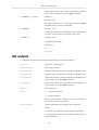
10. Motor Controls & Drive ................................................................................. 43
Drive commands ......................................................................................... 43
Commands ................................................................................................. 43
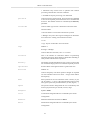
Parameters ................................................................................................. 44
list output ................................................................................................. 46
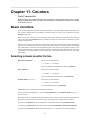
11. Counters ....................................................................................................... 49
Beam monitors ........................................................................................... 49
Selecting a beam monitor for bm ........................................................... 49
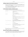
Setting modes for the beam monitors ...................................................... 50
Active beam monitor commands (bm) ..................................................... 50
Specific beam monitor commands (bm1) ................................................. 50
Commands used on both active (bm) and specific (bm1) beam monitors ......... 51
Configuring counters .................................................................................... 52
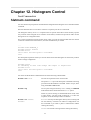
12. Histogram Control .......................................................................................... 53
histmem command ...................................................................................... 53
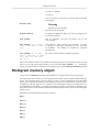
Histogram memory object ............................................................................. 55
13. Simple Scans ................................................................................................. 57
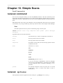
runscan command ...................................................................................... 57
runscan options .................................................................................. 57
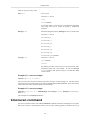
bmonscan command .................................................................................... 58
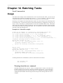
14. Batching Tasks .............................................................................................. 61
Usage ........................................................................................................ 61
Commands ................................................................................................. 62
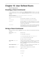
15. User Defined Scans ........................................................................................ 64
Creating a Scan Command ............................................................................ 64
Using a Scan Command ............................................................................... 64
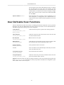
User Definable Scan Functions ...................................................................... 67
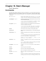
16. Batch Manager .............................................................................................. 68
Commands ................................................................................................. 68
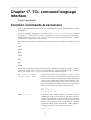
17. TCL command language interface ..................................................................... 70
Common commands & exclusions .................................................................. 70
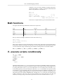
Math functions ............................................................................................ 71
if - execute scripts conditionally .................................................................... 71
for - "for" loop ........................................................................................... 72
while - execute script repeatedly as long as a condition is met .............................. 72
IV. CONFIGURATION AND TROUBLESHOOTING ...................................................... 73
18. Personal configuration .................................................................................... 75
Personalised configuration. extraconfig.tcl ....................................................... 75
Adding a procedure ............................................................................. 75
Adding a variable ................................................................................ 75
19. Motor Configuration ....................................................................................... 77
v
SICS User Manual for Small
Angle Scattering. Quokka Edition
Configuration example .................................................................................
Configuration checklist .................................................................................
For each axis with an absolute encoder ...................................................
For each axis without an absolute encoder ...............................................
For all axes ........................................................................................
Slits ..................................................................................................
Testing ..............................................................................................
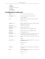
Configuration reference ................................................................................
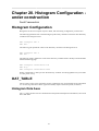
20. Histogram Configuration - under construction .....................................................
Histogram Configuration ..............................................................................
OAT_TABLE .............................................................................................
Histogram Data Axes ...........................................................................
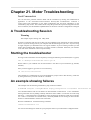
21. Motor Troubleshooting ....................................................................................
A Troubleshooting Session ............................................................................
Starting the troubleshooter ............................................................................
An example showing failures ........................................................................
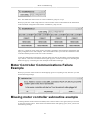
Motor Controller Communications Failure Example ...........................................
Missing motor controller subroutine example ...................................................
Motor controller thread not running example ....................................................
Final status display ......................................................................................
Using sicsclient for troubleshoot ....................................................................
vi
77
78
78
78
78
78
78
79
81
81
81
81
82
82
82
82
83
83
84
84
84
List of Figures
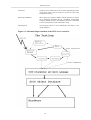
9.1. Schematic Representation of the SICS server structure ................................................ 36
vii
List of Examples
13.1.
13.2.
13.3.
14.1.
17.1.
17.2.
17.3.
19.1.
runscan example .................................................................................................
runscan example .................................................................................................
bmonscan example ...............................................................................................
Batch file example ...............................................................................................
"if" ....................................................................................................................
"for" ..................................................................................................................
"while" ..............................................................................................................
Motor configuration example .................................................................................
viii
58
58
60
61
72
72
72
77
Part I. INTRODUCTION
Table of Contents
1. SICS - The Instrument Control Server .......................................................................... 3
Safety ................................................................................................................. 3
What is SICS ....................................................................................................... 3
Should I read further? ............................................................................................ 4
Where is SICS? .................................................................................................... 4
Starting and stopping SICS using runsics .................................................................. 4
Login to SICS ...................................................................................................... 5
Starting SICS from the command line ...................................................................... 5
SICS Directory Structure ........................................................................................ 5
SICS Configuration ............................................................................................... 6
2. Control, interrupt and system commands ....................................................................... 7
Introduction ......................................................................................................... 7
System Commands and Concepts ............................................................................. 7
Authorisation ................................................................................................ 7
General Structure .......................................................................................... 7
SICS Command Syntax ................................................................................ 8
SICS Variables ............................................................................................. 8
Commonly Used SICS Commands ................................................................... 8
SICS System Commands .............................................................................. 10
Deprecated commands .................................................................................. 11
Logging your activity ........................................................................................... 12
LogBook command ..................................................................................... 12
The Commandlog ........................................................................................ 12
GetLog Command ....................................................................................... 13
Connection Configuration Commands ..................................................................... 14
Config command ......................................................................................... 14
3. Interrupting SICS .................................................................................................... 16
Safety ................................................................................................................ 16
stopexe command ................................................................................................ 16
Interrupting SICS ................................................................................................ 16
4. File commands ........................................................................................................ 18
Introduction ........................................................................................................ 18
Filenames .................................................................................................. 18
File Format. NeXus ..................................................................................... 18
File Content ............................................................................................... 18
File Locations ............................................................................................. 19
File Commands. Single Files ................................................................................. 19
newfile command ........................................................................................ 19
save command ............................................................................................ 20
Other single file commands ........................................................................... 20
File Collection Commands .................................................................................... 20
newfile_collection command ......................................................................... 20
save_collection command ............................................................................. 21
2
Chapter 1. SICS - The Instrument
Control Server
Ferdi Franceschini
Safety
SICS is NOT a safety system! It will allow you to do tasks that may damage persons and the
instruments.
DO use the STAR principle. STOP. THINK. ACT. REVIEW
Familiarise yourself the location of the Emergency Stop buttons located near the cabin exit, or in
several places within the instrument enclosure.
Familiarise yourself with the instrument and its safe operation.
DO NOT do anything with SICS that may risk damage to persons or the instrument.
DO NOT rely on these commands to stop motors or close shutters. If in any doubt, use the Emergency
Stop button.
The commands in this chapter may fail for a variety of reasons.
• SICS has crashed
• Your network connection to the SICS is blocked, due to network congestion or failure
• The motor controller is no longer accepting connections or has a rogue process running
What is SICS
Neutron scattering experiments require control of motors for instrument configuration, control of
histogram memory for counting neutrons, and control of sample environment. SICS is a program that
accepts human readable commands, and converts these to commands that devices understand. For
simplicity, much of the control for an experiment is done in a sequence (synchronously), requiring
that an operation completes successfully before the next is commenced. SICS can also be used
asynchronously, but more care has to be exercised by the operator to ensure the desire result.
Instrument control is based on a client server architecture, each instrument has a dedicated server,
called SICS, which receives commands from client applications and then executes them by issuing
control sequences to the hardware. SICS was originally developed at PSI to control the SINQ
spallation source instruments. Drivers and site specific extensions have been developed at ANSTO
to control and provide status information for motors, sample environment and histogrammed neutron
event data from the detectors.
Driving a device synchronously is done using the drive command. The device could be a motor or
sample environment e.g. temperature controller.
Driving a devices asychronously is done using the run command.
Stopping the device is done using the stopexe command.
Counting of histogrammed neutron events is done using the histmem command.
3
SICS - The Instrument
Control Server
Running scans that are a linear sequence of driving, counting and file saving tasks is done using the
runscan command.
Creating a new file is done using the newfile command, and saving data to the file is done using the
save command.
Detail for using each of these commands is provided in the next chapter. SICS provides many other
functions, but we won't cloud the issue at this stage.
Should I read further?
In general, the Bragg Institute instrument scientists manage SICS for the instrument users. SICS should
be running when you come to the instrument, and you should only need to run the Gumtree program.
You should read further if you think that SICS is not running and you want to start it, you want to
command a device directly with SICS (the first half of this manual), or you would like to change the
instrument configuration (the second half).
Where is SICS?
SICS runs on an ICS computer (instrument control server). All ICS computers run the Linux operating
system, and have a name that looks like ics1-echidna.nbi.ansto.gov.au. If you have an account on the
NBI network, you can use that username and password to login. You must login using ssh from a unix
computer, or using an ssh client on a Microsoft Windows computer like putty or F-Secure
Starting and stopping SICS using runsics
To control the instrument, the SICS software must be running on the instrument control computer.
First, check to see if SICS is already running by calling the runsics status command as shown
below. Note: the "echidna@ics1-echidna:~>" is just the command line prompt.
echidna@ics1-echidna:~> runsics status
SICServer running
SICS script validator running
This example shows SICS is already running. In this case, you should proceed to login to SICS.
If the reply is
echidna@ics1-echidna:~> runsics status
SICServer NOT running
SICS script validator NOT running
then use the runsics start command
echidna@ics1-echidna:~> runsics start
Starting SICS
29087
SUCCESS
Starting SICS Script Validator
4
SICS - The Instrument
Control Server
29091
SUCCESS
Login to SICS
Most users won't want to login to SICS. However, if you do need to get to the SICS command line,
then use the sicsclient command at the Linux prompt.
echidna@ics1-echidna:~> sicsclient
OK
Now you'll have to login to SICS with your role and password. The role is spy, user or
manager, and the instrument scientist will provide you with the password.
myusername mypassword
Login OK
When a correct username and password is entered, SICS announces that the login was successful.
SICS commands can now be entered.
Starting SICS from the command line
To start SICS you have to log on to the instrument control computer and then
cd /usr/local/sics/server
and launch the server in the background with a command similar to the one shown below
cd /usr/local/sics/server
nohup ./SICServer xxx_configuration.tcl &
where xxx is the instrument name.
Note
The '&' is important, it runs the server in the background, nohup logs output from SICS to a
file called nohup.out and ensures that SICS continues running when you logout.The .tcl file
specified on the command line is the configuration file for your instrument, replace the xxx
with your instrument's ID. The configuration file may source other .tcl files.
SICS Directory Structure
SICS is installed on the /usr/local/sics/ directory of the instrument control computer. It has the
following subdirectories
/server
This contains the SICServer and the *.tcl configuration files
/data
Data files are stored here
/log
Server log files are stored here along with the status.tcl file. The
status.tcl file preserves variable settings and some parameter
values from the last session with the SICServer
/tmp
The server keeps temporary files here
5
SICS - The Instrument
Control Server
SICS Configuration
SICS is configured via *.tcl files which initialise the command objects which clients use to control
the hardware. Also, the server's functionality can be extended by defining new commands in the
configuration files, we can do this because SICS embeds a Tcl interpreter (hence the .tcl extension).
6
Chapter 2. Control, interrupt and
system commands
Mark Koennecke
Introduction
In the previous chapter, you learnt how to start and stop SICS, and how to login. Now you'll learn
how to control the instrument.
The first part of this chapter deals with some of the most used commands in SICS. This includes
system commands and control commands. This provides you with a soft start.
The second part of the chapter deals with logging activity and configuring your connection to SICS.
The next chapter will go more deeply into the how SICS executes those commands, through a sequence
of states. You may want to skip the next chapter if you don't require a deeper understanding of SICS.
This chapter and the next are from the master user manual for SICS. It gives an overview over all
commands implemented, independent of a specific instrument. This is to be used as the source for
more instrument specific user manuals and gives an overview of the commands available within SICS.
Please note, that many instruments have special commands realized as scripts in the SICS built in
scripting language. Only the most common of such commands are listed here.
System Commands and Concepts
Authorisation
A client server system is potentially open to unauthorised hackers who might mess up the instrument
and your valuable measurements. A known problem in instrument control is that less knowledgeable
user accidentally change instrument parameters which ought to be left fixed. In order to solve these two
problems SICS supports authorisation on a very fine level. As a user you have to specify a username
and password in order to able to access SICS. Some clients already do this for you automatically. SICS
support four levels of access to an instrument:
Roles
Spy
may look at everything, request any value, but may not actually change anything. No
damage potential here.
User
is privileged to perform a certain amount of operations necessary to run the instrument.
Manager
has the permission to mess with almost everything. A very dangerous person.
Internal
is not accessible to the outside world and is used to circumvent protection for internal
uses. However some parameters are considered to be so critical that they cannot be
changed during the runtime of the SICS-server, not even by Managers.
All this is stated here in order to explain the common error message: You are not authorised to do that
and that or something along these lines.
General Structure
SICS is a client server system. The application the user sees is usually some form of client. A client
has two tasks: the first is to collect user input and send it to the SICS server which then executes the
7
Control, interrupt and
system commands
command. The clients second task is to listen to the server messages and display them in a readable
format. This approach has two advantages: clients can reside on machines across the whole network
thus enabling remote control from everywhere in the world. The second advantage is that new clients
(such as graphical user interface clients) can be written in any feasible language without changes to
the server.
SICS Command Syntax
SICS is an object oriented system. This is reflected in the command syntax. SICS objects can be
devices such as motors, single counters, histogram memories or other hardware variables such as
wavelength or Title and measurement procedures. Communication with these objects happens by
sending messages to the target object. This is very simply done by typing something like: object
message par1 par2 .. parn. For example, if we have a motor called A1:
A1 list
will print a parameter listing for the motor A1. In this example no parameters were needed. There exist
a number of one-word commands as well. For compatibility reasons some commands have a form
which resembles a function call such as:
drive a1 26.54
This will drive motor a1 to 26.54. All commands are ASCII-strings and usually in english. SICS is in
general CASE INSENSITIVE. However, this does not hold for parameters you have to specify. On a
unix system for instance file names are case sensitive and that had to be preserved. Commands defined
in the scripting language are lower case by convention.
Most SICS objects also hold the parameters required for their proper operation. The general syntax
for handling such parameters is:
objectname parametername
prints the current value of the parameter
objectname parametername newvalue
sets the parameter value to newvalue if you are properly authorized.
SICS Variables
Most of the parameters SICS uses are hidden in the objects to which they belong. But some are
separate objects of their own right and are accessible at top level. For instance things like Title or
wavelength. They share a common syntax for changing and requesting their values. This is very simple:
The command objectname will return the value, the command objectname newvalue will change the
variable. But only if the authorisation codes match.
Commonly Used SICS Commands
The most used commands in SICS are:
8
Control, interrupt and
system commands
sicslist interface drivable
prints a list of all drivable objects. This is more than motors
and includes virtual motors, sample environment devices and
wavelength
run device value
run a device to a value
runs any object listed using dir inter driv in non-blocking/
asynchronous mode
drive device value
drive a device to a value
drives any object listed using dir inter driv in blocking/
synchronous mode
stopexe device
interrupts a drive or run command. In the case of motors, the
motor will decelerate. It won't stop immediately, as this can
cause damage to the instrument
Warning
This will not interrupt a scan e.g. runscan.
SICS will continue to accept commands from a client
stopexe all
interrupts all devices. In the case of motors, the motor will
decelerate. It won't stop immediately, as this can cause damage
to the instrument
Warning
This will not interrupt a scan e.g. runscan.
SICS will continue to accept commands from a client
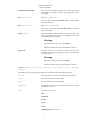
runscan scanvar start stop numpoints mode preset [force datatype
savetype]
Arguments must be in the order described. See more detail in the "Simple Scans" chapter.
scanvar
a drivable device, ie a motor or temperature controller etc
start
the start position for the scan variable
stop
the stop position for the scan variable
numpoints
the number of scan points (the start and stop positions will be
included in the scan)
mode
Allowed mode one of:
time
unlimited
period
count
frame
MONITOR_n (where n=1,2,3 ...)
9
Control, interrupt and
system commands
If you set the mode to MONITOR_1 then the histogram
server will stop when MONITOR_1 reaches the preset number
of counts which has been set with the following preset
parameter
the acquisition duration at each scan point, this is in second
if the mode is time, or counts if the mode is count or
MONITOR_n
preset
INT1712 3
interrupts a runscan command. In the case of motors, the motor will decelerate. It
won't stop immediately, as this can cause damage to the instrument
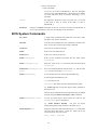
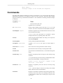
SICS System Commands
sics_exitus
A single word commands which shuts the server down. Only
managers may use this command.
wait time
waits time seconds before the next command is executed. This
does not stop other clients from issuing commands.
resetserver
resets the server after an interrupt.
sicslist
Prints a list of all SICS objects.
sicslist server
Prints a list of all server options.
sicslist sicsobject
Prints all the metadata associated with the SICS object
sicsobject.
sicslist sicsobject key
Prints the value of the key associated with the SICS object
sicsobject.
sicslist setatt sicsobject key
value
Sets a user defined attribute with the name key and the value
value for the SICS object sicsobject.
sicslist metadatakey
List all unique entries for the specified metadata key.
System supplied metadata keys are:
type The object class
interface The object interfaces implemented by SICS
e.g. sicslist type will print all the objects classes available in
the SICS server
This list may be augmented with user generated keys as defined
through using the sicslist setatt obj key value command
sicslist metadatakey value
List all the SICS objects which match the value for the
metadatakey given as parameters.
e.g. sicslist interface drivable
will print all objects
implementing the drivable interface in the SICS server.
sicslist objstatus obj
Will query the current state of the SICS object obj. This makes
sense for things like motors, counter etc. which can be run
asynchronously. The result can be:
idle, fault, busy etc.
10
Control, interrupt and
system commands
sicslist match mask
Will print the names of all SICS objects where the name
matches the wildcard given as mask
status
A single word command which makes SICS print its current
status.
Possible return values can be:
Eager to execute commands
Scanning
Counting
Running
Halted
Note that if a command is executing which takes some time to
complete the server will return an ERROR: Busy message
when further commands are issued.
status interest
initiates automatic printing of any status change in the server.
This command is primarily of interest for status display client
implementors.
backup
saves the current values of SICS variables and selected motor
and device parameters to the disk file specified as parameter.
If no file parameter is given the data is written to the system
default status backup file. The format of the file is a list of SICS
commands to set all these parameters again. The file is written
on the instrument computer relative to the path of the SICS
server. This is usually /home/INSTRUMENT/bin.
backup motsave
toggles a #ag which controls saving of motor positions. If this
#ag is set, commands for driving motors to the current positions
are included in the backup file. This is useful for instruments
with slipping motors.
restore
reads a file produced by the backup command described above
and restores SICS to the state it was in when the status was
saved with backup. If no file argument is given the system
default file gets read.
restore listerr
prints the list of lines which caused errors during the last
restore.
killfile
decrements the data number used for SICS file writing and
thus consequently overwrites the last datafile. This is useful
when useless data files have been created during tests. As this
is critical command in normal user operations, this command
requires managers privilege.
sicsidle
prints the number of seconds since the last invocation of a
counting or driving operation. Used in scripts.
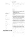
Deprecated commands
dir
DEPRECATED: use sicslist a command which lists objects
available in the SICS system. Without any options prints a list
of all objects. The list can be restricted with:
11
Control, interrupt and
system commands
dir var
DEPRECATED: use sicslistprints all SICS primitive
variables
dir mot
DEPRECATED: use sicslistprints a list of all motors
dir inter driv
DEPRECATED: use sicslistprints a list of all drivable objects.
This is more than motors and includes virtual motors such as
environment devices and wavelength as well.
dir inter count
DEPRECATED: use sicslistShows everything which can be
counted upon.
dir inter env
DEPRECATED: use sicslistShows all currently configured
environment devices.
dir match wildcard
DEPRECATED: use sicslistlists all objects which match the
wildcard string given in wildcard - doesn't work
Logging your activity
SICS offers not less then three different ways of logging your commands and the SICS server’s
responses
• You may create a similar per client log file on the computer running the SICS server through the
logbook command.
• Then there is a way to log all activity registered from users with either user or manager privilege
into a file. This means all commands which affect the experiment regardless from which client they
have been issued. This is accomplished with the commandlog command.
• the GetLog command receives messages from all active clients. This allows you to view all events
on your connection, and is intended for debugging.
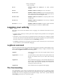
LogBook command
Some users like to have all the input typed to SICS and responses collected in a file for further review.
This is implemented via the LogBook command. LogBook is actually a wrapper around the config
file command. LogBook understands the following syntax:
LogBook
alone prints the name of the current logfile and the status of
event logging.
LogBook file filename
sets the filename to which output will be printed. Please note
that this new filename will only be in effect after restarting
logging.
LogBook on
This command turns logging on. All commands and all answers
will be written to the file defined with the command described
above. Please note, that this command will overwrite an
existing file with the same name.
LogBook off
This command closes the logfile and ends logging.
The Commandlog
The Commandlog is a file where all communication with clients having user or manager privilege
is logged. This log allows to retrace each step of an experiment. This log is normally configured in
the startup file or can be configured by the instrument manager. There exists a special command,
Commandlog, which allows to control this log file.
12
Control, interrupt and
system commands
Commandlog new filename
starts a new commandlog writing to filename. Any prior
files will be closed. The log file can be found in the directory
specified by the ServerOption LogFileDir. Usually this is the
log directory.
Commandlog
displays the status of the commandlog.
Commandlog close
closes the commandlog file.
Commandlog auto
Switches automatic log file creation on. This is normally
switched on. Log files are written to the log directory of the
instrument account. There are time stamps any hour in that file
and there is a new file any 24 hours.
Commandlog tail n
prints the last n entries made into the command log. n is
optional and defaults to 20. Up to 1000 lines are held in an
internal buffer for this command.
Commandlog intervall
minutes
Queries and configures the intervall in minutes at which time
stamps are written to the commandlog.
It is now possible to have a script executed whenever a new log file is started. In order to make this
work a ServerOption with the name logstartfile must exist in the instrument configuration file. The
value of this option must be the full path name of the file to execute.
Note: with the command config listen 1 you can have the output to the command log printed into
your client, too. With config listen 0 you can switch this off again. This is useful for listening into
a running instrument.
GetLog Command
The SICS server logs all its activities to a logfile, regardless of what the user requested. This logfile
is mainly intended to help in server debugging. However, clients may register an interest in certain
server events and can have them displayed. This facility is accessed via the GetLog command. It
needs to be stressed that this log receives messages from all active clients. GetLog understands the
following messages:
GetLog All
achieves that all output to the server logfile is also written to
the client which issued this command.
GetLog Kill
stops all logging output to the client.
GetLog OutCode
request that only certain events will be logged to the client
issuing this command. Enables only the level specified.
Multiple calls are possible.
Possible values for OutCode are:
Internal internal errors such as memory errors etc.
Command all commands issued from any client to the server.
HWError all errors generated by instrument hardware. The
SICS server tries hard to fix HW errors in order to achieve
stable operations and may not generate an error message if it
was able to fix the problem. This option may be very helpful
when tracking dodgy devices.
InError All input errors found on any clients input.
13
Control, interrupt and
system commands
Error All error messages generated by all clients.
Status some commands send status messages to the client
invoking the command in order to monitor the state of a scan.
Value Some commands return requested values to a user.
These messages have an output code of Value.
Connection Configuration Commands
SICS has a command for changing the user rights of the current client server connection, control the
amount of output a client receives and to specify additional logfiles where output will be placed. All
this is accessed through the following commands:
Config command
The config command configures various aspects of the current client server connection. Basically
three things can be manipulated: The connections output class, the user rights associated with it, and
output files.
config OutCode val
sets the output code for the connection. By default all output
is sent to the client. But a graphical user interface client might
want to restrict message to only those delivering requested
values and error messages and suppressing anything else. In
order to achieve this, this command is provided.
Possible values: Values for val are
Internal
Command
HWError
InError
Status
Error
Value
This list is hierarchical. For example specifying InError for
val lets the client receive all messages tagged InError,
Status,
Error and Value, but not HWError,
Command and Internal messages.
config Rights Username
Password
Each connection between a client and the SICS server has user
rights assocociated with it. These user rights can be configured
at runtime with the command config Rights Username
Password. If a matching entry can be found in the servers
password database new rights will be set.
config File name
Scientists are not content with having output on the screen. In
order to check results a log of all output may be required. The
command config File name makes all output to the client to be
written to the file specified by name as well. The file must be
a file accessible to the server, i.e. reside on the same machine
14
Control, interrupt and
system commands
as the server. Up to 10 logfiles can be specified. Note, that a
directly connected line printer is only a special filename in unix.
config close num
closes the log file denoted by num again.
config list
lists the currently active values for outcode and user rights.
config myname
returns the name of the connection.
config myrights
prints the rights associated with your connection.
config listen val
switches listening to the commandlog on or off for this
conenction. If this on, all output to the commandlog, i.e.
all interesting things happening in SICS, is printed to your
connection as well.
val = 0 is off
val = 1 is on
15
Chapter 3. Interrupting SICS
Ferdi Franceschini
Safety
SICS is NOT a safety system! It will allow you to do tasks that may damage persons and the
instruments.
DO use the STAR principle. STOP. THINK. ACT. REVIEW
Familiarise yourself the location of the Emergency Stop buttons located near the cabin exit, or in
several places within the instrument enclosure.
Familiarise yourself with the instrument and its safe operation.
DO NOT do anything with SICS that may risk damage to persons or the instrument.
DO NOT rely on these commands to stop motors or close shutters. If in any doubt, use the Emergency
Stop button.
The commands in this chapter may fail for a variety of reasons.
• SICS has crashed
• Your network connection to the SICS is blocked, due to network congestion or failure
• The motor controller is no longer accepting connections or has a rogue process running
stopexe command
The stopexe command will stop drivable objects. It will NOT stop scans or batch files. For that you'll
have to use an interrupt as found in the next section.
stopexe device
interrupts a drive or run command. In the case of motors, the
motor will decelerate. It won't stop immediately, as this can
cause damage to the instrument
Warning
This will not interrupt a scan e.g. runscan.
SICS will continue to accept commands from a client
stopexe all
interrupts all devices. In the case of motors, the motor will
decelerate. It won't stop immediately, as this can cause damage
to the instrument
Warning
This will not interrupt a scan e.g. runscan.
SICS will continue to accept commands from a client
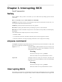
Interrupting SICS
On occasion, you as the user, or a SICS object may come to the conclusion that an error is so bad that
the measurement needs to be stopped. Clearly a means is needed to communicate this to upper level
16
Interrupting SICS
code. This means is setting an interrupt on the connection. The current active interrupt is located at the
connection object (note for SICS programmers, this can be retrieved with SCGetInterrupt and set with
SCSetInterrupt. Interrupt codes are defined in interrupt.h). These codes are ordered into a hierarchy
INT1712 0
Continue. Everything is just fine. eContinue
INT1712 1
Abort Operation.
Stop the current scan point or whatever is done, but do not stop altogether.
eAbortOperation
INT1712 2
Abort Scan.
Abort the current scan, but continue processing of further commands in buffers or
command #les. eAbortScan
INT1712 3
Abort Batch.
Aborts everything, operations, scans and batch processing and leaves the system
ready to enter new commands. eAbortBatch
INT1712 4
Halt System.
As eAbortBatch, but lock the system. eHaltSystem
INT1712 5
Free System
Unlocks a system halted with eHaltSystem. eFreeSystem
INT1712 6
Warning
For internal usage only
Makes the SICS server run down and exit. .
Higher level SICS objects may come to the conclusion that the error reported by lower level code is
actually not that critical and clear any pending interrupts by setting the interrupt code to eContinue
and thus consume the interrupt.
17
Chapter 4. File commands
Ferdi Franceschini
Introduction
Filenames
SICS provides methods to create and save files. You can create a single file, and save either a single
dataset, or multiple datasets to the one file. You can also create and manage collections of files, and
save single or multiple datasets to files in the collection
SICS automatically creates the filename. The filenames have the form
xxxnnnnnnn.nx.hdf
where xxx is a 3 letter abbreviation of the instrument
QKK - quokka
ECH - echidna
WOM - wombat
KOW - kowari
PLA - platypus
nnnnnnn is a 7 numeral sequence number, starting at 0000000 when the
facility commenced operation, and is automatically incremented by SICS.
The file /usr/local/sics/DataNumber is used to keep track of the number.
DO NOT edit this file.
.nx denotes that the file is a NeXus file.
.hdf denotes the file is an hdf5 (binary) file.
e.g. QKK0001234.nx.hdf
File Format. NeXus
Files are saved using the ANSTO interpretation of the NeXus standard.
SICS support both the xml and hdf5 form. For performance of reading and writing, by default we
write hdf5 binary.
SICS can also be configured to write xml. This is set in nxscripts_common_1.tcl. Set the
file,format element of the state array to "xml"
File Content
This section will give only a very brief overview of NeXus. Further reading can be found at the NeXus
webite, www.nexusformat.org
NeXus is a hierachical data format; data is saved in groups and these groups live under entries. It
a similar structure to directories on a file system. We have made a policy decision at the Bragg
Institute to have only one entry per file. This entry may contain a variable parameter or scan, where
e.g. temperature is varied. If you use the runscan command, histogram data is taken at discrete
18
File commands
temperatures. Temperature will be a vector in the file, and the histogram data may be a data cube of
2 dimensional x,y or 3 dimensional x,y,t histogram arrays.
There are 4 groups in NeXus. User, Sample, Instrument and Data. SICS will write the data it acquires
to one of these groups. The content that is saved, and where in the file it is saved to is controlled by
configuration files.
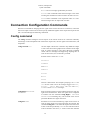
/usr/local/sics/server/config/nexus contains *.dic dictionary files. These files tell
SICS how to map a SICS object to a location in a NeXus file, and what type the data will be, and its
attributes e.g units. Below is an example from nexus.dic
samphi = /entry1,NXentry/sample,NXsample/SDS sample_phi
-type NX_FLOAT32 -rank 1 -dim {-1}
-attr {units,degrees}
-attr {long_name,sample_phi}
Changes to configurations are done by the facility. Dictionaries can be checked with check_instdict.tcl
and check_sicsobj_attributes.tcl.
By default, if the SICS object exists and there is an entry in the dictionary, then it will be saved to
the data file. There is a second hierarchy of SICS objects which is used by Gumtree for control. This
is called hipadaba. We won't go into detail about hipadaba in this manual, but it is important for this
discussion to know how hipadaba controls saving of SICS objects. Hipadaba has the same structure
as NeXus. The hipadaba tree when initially created by SICS is a complete NeXus tree, which is then
pruned to contain only those nodes that exist for that instrument. This allows any node to be added
to nexus.dic for an instrument without having to change hipadaba. There are dictionary files for
hipadaba found at /usr/local/sics/server/config/hipadaba/. In general, there is no
instrument specific information in these files. Every node in hipadaba has data and nxsave attributes.
By default, nxsave is set to true, and if the node contains data, data is set to true. If either of these is
set to false, then the data will not be saved.
File Locations
File are written to /usr/local/sics/data of the ics1-australian_fauna computer. This
path is configured in server_config.tcl by setting the SicsDataPath variable. Posix
symbolic links are used to link the directory to the appropriate directory on filer.nbi.ansto.gov.au,
under the /experiments mount point. You can mount this directory on the MS Windows machine
dav1-australian_fauna.
File Commands. Single Files
newfile command
newfile file_type [scratch]
creates a new file of type file_type ready to write to. The
command does write any information to disk.
To save data, use the save command.
You can only hold a reference to one file. If you need to
reference a number of files, then use newfile_collection.
Only use the optional [scratch] if you want to write data
to a scratch file. The file will be overwritten with the next
invocation of this option
file_type may have the following values:
BEAM_MONITOR Saves data from the configured beam
monitors, histogram memory data is not saved.
19
File commands
HISTOGRAM_T Saves histogram total time data and beam
monitor data.
HISTOGRAM_X Saves histogram x data and beam monitor
data.
HISTOGRAM_XT Saves histogram x,t data and beam monitor
data.
HISTOGRAM_Y Saves histogram y data and beam monitor
data.
HISTOGRAM_YT Saves histogram y,t data and beam monitor
data.
HISTOGRAM_XY Saves histogram x,y data and beam monitor
data.
HISTOGRAM_XYT Saves histogram total x,y,t data and beam
monitor data.
save command
save index
saves data to disk.
index is the index of data to be saved, starting with 0. To save
your first slice of data you would save 0. This provides you with
a complete NeXus file. You may be doing After you acquire
you next slice of data, you would save 1, then save 2 etc.
Other single file commands
killfile
decrements the data number used for SICS file writing and thus consequently overwrites
the last datafile. This is useful when useless data files have been created during tests.
As this is critical command in normal user operations, this command requires managers
privilege.
File Collection Commands
newfile_collection command
newfile_collection -labels
{sample1 sample2} filetype file_type savetype save_type
Whereas newfile creates one file, newfile_collection will create
as many files as there are labels. The command does write any
information to disk.
To save data, use the save_collection command
Example: You have a multi-sample changer or robot. You want
to do a measurement on each sample at multiple temperatures.
Your experimental sequence has the sample changer as the
fastest varying parameter (inner loop), and temperature change
as the slowest varying parameter (outer loop). You want to
record all temperature data for a sample in one file.
-savetype save_type may have the following values:
data writes to a normal data file
20
File commands
scratch writes to a scratch file. The file will be overwritten
with the next invocation of this option. Used mainly for testing.
-filetype file_type may have the following values:
BEAM_MONITOR Saves data from the configured beam
monitors, histogram memory data is not saved.
HISTOGRAM_T Saves histogram total time data and beam
monitor data.
HISTOGRAM_X Saves histogram x data and beam monitor
data.
HISTOGRAM_XT Saves histogram x,t data and beam monitor
data.
HISTOGRAM_Y Saves histogram y data and beam monitor
data.
HISTOGRAM_YT Saves histogram y,t data and beam monitor
data.
HISTOGRAM_XY Saves histogram x,y data and beam monitor
data.
HISTOGRAM_XYT Saves histogram total x,y,t data and beam
monitor data.
save_collection command
save_collection -index val labels sample1
saves data to disk within a collection (multiple files)
-indexval is the index of data to be saved, starting with 0. To
save your first slice of data you would save 0. This provides
you with a complete NeXus file. You may be doing After you
acquire you next slice of data, you would save 1, then save 2 etc.
-labels sample1 will save to the file referenced by the label
sample1. You would put all data relating to a sample into this
one file.
21
Part II. QUOKKA
SPECIFIC COMMANDS
Table of Contents
5. Ordela Detector Voltage Control ................................................................................
Commands .........................................................................................................
Parameters .........................................................................................................
6. Beamstops ..............................................................................................................
Commands .........................................................................................................
Troubleshooting ..................................................................................................
7. Astrium Velocity Selector .........................................................................................
Commands .........................................................................................................
Parameters .........................................................................................................
8. Julabo Temperature Control .......................................................................................
Commands .........................................................................................................
Parameters .........................................................................................................
23
24
24
24
26
26
26
27
27
28
30
30
30
Chapter 5. Ordela Detector Voltage
Control
Ferdi Franceschini
Commands
The High Voltage controller for the Ordela detector has been implemented as a standard SICS
environment controller object with a driveable interface. It has been configured differently to other
SICS objects in several ways. Firstly, you use up and down commands to drive the voltage to its
upper and lower limits. This is a blocking task i.e. no other task can started until this is complete.
Secondly, the instrument has been configured with the SICS anticollider to prevent you from moving
the detector when the voltage is above a certain threshold, which will lead to damage of the detector.
This is important for Quokka as the detector is moved frequently.
dhv1 up
Raise the voltage
dhv1 down
Lower the voltage
Note
NOTE This command blocks until the power supply reaches the
"upper" or "lower" running voltages, see below.
INT1712 1
If this commands hang SICS you can interrupt it with by entering this at
the SICS command line, or by pressing the interrupt button at the bottom
of GumTree
dhv1 reset
Reset the controller
dhv1 list
Displays the values of the various parameters
dhv1 send command
Sends a command to the unit and displays the response
dhv1 off
Drives the output voltage to zero
Parameters
dhv1 upper voltage
Sets the running voltage for the up command. This would normally be
the operating voltage for the equipment to which the power supply is
connected.
dhv1 lower voltage
Sets the standby voltage for the down command. This would normally
be the standby voltage for the equipment to which the power supply is
connected.
dhv1 max voltage
Sets the hardware maximum for the power supply. For the Ordela power
supplies, it is important that this is the correct full-scale value of the
power supply itself. This is used to convert between the voltage step and
voltages and to calculate the step period from the voltage slew rate.
dhv1 rate voltage
The volts per second at which the power supply slews between voltages.
For the Ordela power supplies, this is used to calculate the time between
voltage steps based on the max parameter
dhv1 debug val
Allowed val
24
Ordela Detector Voltage Control
0 No debug information in log
1 Debug information in log
dhv1 lock
This locks the device from being set by users. Users can use up down
and off commands to set voltages
dhv1 unlock
Managers may unlock the device
25
Chapter 6. Beamstops
Ferdi Franceschini
Commands
Raising and lowering of beamstops is implemented via action objects, you control them via the action
and waitaction commands.
action bs1 position
Will send beamstop bs1 either up or down
Allowed position
up
down
bs1 status
this will report one of the following:
bs1 = up,
bs1 = down
bs1 = inbetween
Note
Currently there is no automatic notification when a
move is complete
waitaction bs1
If you want to sequence some commands in a batch file, you
can use the waitaction command
e.g. If you put these lines in a batch file the histogram memory
won't start counting until the beamstop is up
waitaction bs1 up
histmem start
Troubleshooting
Beamstop position can be checked visually (by eyes) from the vessel port with touch. To do this, you
should drive the detector to position 9300mm, and view from the middle vessel port.
26
Chapter 7. Astrium Velocity Selector
Nick Hauser
Commands
The Astrium velocity selector is a SICS script context object. There are 2 parts, the script context
object, which has the name /instrument/velocity_selector and the 2 driveable interfaces to the object,
which have the names nvs_speed and nvs_lambda. Hence you can drive and run nvs_speed and
nvs_lambda. To get and set other parameters use hget or hset /instrument/velocity_selector/
run nvs_lambda wavelength
Units: Angstroms
Runs the velocity selector to wavelength
drive nvs_lambda
wavelength
Units: Angstroms
Is the same as run but it blocks the client that requested the
drive from issuing commands until the task has finished.
hset /instrument/
velocity_selector/setstate brake
Set the state. The state can be read using hget /instrument/
velocity_selector/state
If the state is set to brake , then hget /instrument/
velocity_selector/state will return BRAKING even when the
rotor has stopped.
You can use run nvs_speed to run the rotor again
Allowed values:
brake
hget /instrument/
velocity_selector/state
Get the state. The normal operating state under SICS control
is CONTROL
hlist /instrument/
velocity_selector
Lists all the velocity_selector nodes
hset /instrument/
velocity_selector/node val
Set val on a node
hget /instrument/
velocity_selector/node
Get the value of a node
hset /instrument/
velocity_selector/setspeed val
Privilege = User
Units = rpm
Set the rotor set speed.
Once this is set, the velocity selector will attempt to run to this
speed.
If called with no argument, will return an error
The velocity selector is under the /instrument/velocity_selector node in hipadaba, which
is where it will be found when using the Gumtree TableTree. This complies with the NeXus standard.
27
Astrium Velocity Selector
Parameters
For more detailed description of these parameter, please see the ASTRIUM velocity selector
manual on ANSTOnet.
hget /instrument/
velocity_selector/wvalv
Privilege = User
Get the state of the water valve. The water valve will open in
once the velocity selector has reached 3000 rpm. The valve will
close again and the selector will brake to 0 rpm if the water
flow is not within tolerance.
open Water valve open
clos Water valve closed
hget /instrument/
velocity_selector/rtemp
Privilege = User
Units = Celsius
Get the rotor temperature.
hget /instrument/
velocity_selector/state
Privilege = User
Get the state.
IDLING Is not being controlled. Should be at zero rpm.
RESET A reset has been issued by the velocity selector client
program
CONTROL Control has been requested by SICS or the velocity
selector client program
BRAKING The velocity selector has the brake applied due to
an hset setstate brake request, the Brake button applied on the
velocity selector client program, or due to a fault condition
POWERLOSS MEASUREMENT Powerloss measurement button
applied on the velocity selector client program
EMERGENCY STOP Emergency stop button applied on the
velocity selector client program
hget /instrument/
velocity_selector/aspeed
Units = rpm
Get the actual speed
hget /instrument/
velocity_selector/sspeed val
Privilege = User
Units = rpm
No idea ???
hget /instrument/
velocity_selector/winlt
Units = Celsius
Get the cooling water inlet temperature
hget /instrument/
velocity_selector/wflow
Units = litres/min
Get the cooling water flow rate
28
Astrium Velocity Selector
hget /instrument/
velocity_selector/ploss
Units = Watts
Get the last measured power loss
hget /instrument/
velocity_selector/splos
Units = rpm
Get the speed of the last measured power loss
hget /instrument/
velocity_selector/rspeed
Units = rpm
Get the requested speed, set using run nvs_speed
hget /instrument/
velocity_selector/woutt
Units = Celsius
Get the cooling water outlet temperature
hget /instrument/
velocity_selector/vacum
Units = 10-3bar
Get the vacuum
hget /instrument/
velocity_selector/bcuun
Get the BCU units
hget /instrument/
velocity_selector/ttang
Units = degrees
Get the turntable angle. 999.99 if not initialised
hget /instrument/
velocity_selector/vibrt
Units = mm/s
Get the vibration
hget /instrument/
velocity_selector/vvalv
Get the vacuum valve state
Returned values:
open
closed
hget /instrument/
velocity_selector/aveto
Get the veto state
Returned values:
nok not OK
ok OK
29
Chapter 8. Julabo Temperature
Control
Nick Hauser
Commands
The Julabo temperature controller is a SICS script context object. There are 2 parts, the script context
object, which has the name /sample/tc1 and the driveable interface to the object, which has the name
tc1_driveable ie. "tee-cee-one". Note this name can change in the configuration. Hence you can drive
and run tc1_driveable. To get and set other parameters use hget or hset /sample/tc1
run tc1_driveable temp1
Runs the temperature controller tc1 to temp1
drive tc1_driveable temp1
Is the same as run but it blocks the client that requested the
drive from issuing commands until the task has finished.
hlist /sample/tc1
Lists all the tc1 nodes. Nodes can be get and set using hget and
hset
The temperature controller is usually put under the /sample node in hipadaba, which is where it will
be found when using the Gumtree SICS. This complies with the NeXus standard.
Parameters
Use hget and hset on these parameters. Parameter without val are read only and therefore cannot
be set.
/sample/tc1/setpoint val
Privilege = User
Units = Celsius
Get/Set the temperature setpoint. If the setpoint is set, the
controller will change the temperature to this value, subject
to constraints including operate remote_ctrl hitemp lotemp
upperlimit lowerlimit
/sample/tc1/overtemp_warnlimit
val
Privilege = User
Units = Celsius
Get/Set the controller's temperature upper limit. When the
temperature is > val, SICS will veto counters until the
temperature fall below val .
/sample/tc1/subtemp_warnlimit
val
Privilege = User
Units = Celsius
Get/Set the controller's temperature lower limit. When the
temperature is < val, SICS will veto the histogram memory
and counters until the temperature rises above val .
/sample/tc1/sensor/value
Units = Celsius
Get the controller's temperature sensor value
30
Julabo Temperature Control
/sample/
tc1/heating_power_percent val
Units = percent
Get the controller's current heating power
/sample/tc1/operate val
Privilege = User
Get/Set the operate state.
Allowed val:
0 Controller doesn't control temperature. Will still report
parameters
1 Controller provides control.
/sample/tc1/status
Get the controller's operate state
Allowed val:
Busy Equivalent to tc1 operate 1
Idle Equivalent to tc1 operate 0
/sample/tc1/remote_ctrl val
Privilege = User
Get/Set remote control enable/disable
Allowed val:
True tc1 remote control enabled
False tc1 remote control disabled
/sample/tc1/lh45_lasterror
Get the last error recorded on the controller. Note that this error
condition is not cleared if the error no longer exists. This value
is only overwritten by another error state.
Example of an error state:
-04 LOW TEMPERATURE WARNING
/sample/tc1/tolerance val
Privilege = User
Units = Celsius
Get/Set tolerance.
overtemp_warnlimit and subtemp_warnlimit will be set
when you use the run or drive tc1
temp1.
Control is dependent on the overtemp_warnlimit and
subtemp_warnlimit values, not on tolerance. Setting
overtemp_warnlimit or subtemp_warnlimit will override
tolerance
/sample/tc1/apply_tolerance
val
Privilege = User
Get/Set apply_tolerance Don't know what this does
Allowed val:
0
1
31
Julabo Temperature Control
/sample/tc1/lowerlimit val
Privilege = Manager
Get/Set the lower limit for setpoint. If you try to set setpoint
below this value, will return.
ERROR: setpoint violates limits
/sample/tc1/upperlimit val
Privilege = Manager
Get/Set the lower limit for setpoint. If you try to set setpoint
above this value, will return.
ERROR: setpoint violates limits
/sample/tc1/emon/monmode
Get emon's monitor mode Don't know what this does
Returned values:
monitor
???
/sample/tc1/emon/isintol
Get if the value is within tolerance (but which tolerance?)
hitemp lotemp or tolerance
Returned values:
0 out of tolerance
1 in tolerance
/sample/tc1/emon/errhandler
Get if the value is within tolerance (but which tolerance?)
hitemp lotemp or tolerance
Returned values:
pause ???
??? ???
32
Part III. COMMANDS IN DETAIL
Table of Contents
9. SICS Overview ....................................................................................................... 35
Introduction ........................................................................................................ 35
SICS Overall Design ........................................................................................... 35
SICS Clients ....................................................................................................... 35
The SICS Server ................................................................................................. 35
The SICS Server Kernel ....................................................................................... 37
The SICS Interpreter ............................................................................................ 38
SICS Objects ...................................................................................................... 38
SICS Working Examples ...................................................................................... 39
The Request for a new Client Connection ........................................................ 39
A Simple Command .................................................................................... 39
A "drive" Command in Blocking Mode ........................................................... 40
A "drive" Command Interrupted .................................................................... 40
A "run" Command in Non Blocking Mode ....................................................... 41
10. Motor Controls & Drive ......................................................................................... 43
Drive commands ................................................................................................. 43
Commands ......................................................................................................... 43
Parameters ......................................................................................................... 44
list output ......................................................................................................... 46
11. Counters ............................................................................................................... 49
Beam monitors ................................................................................................... 49
Selecting a beam monitor for bm ................................................................... 49
Setting modes for the beam monitors .............................................................. 50
Active beam monitor commands (bm) ............................................................. 50
Specific beam monitor commands (bm1) ......................................................... 50
Commands used on both active (bm) and specific (bm1) beam monitors ................. 51
Configuring counters ............................................................................................ 52
12. Histogram Control .................................................................................................. 53
histmem command .............................................................................................. 53
Histogram memory object ..................................................................................... 55
13. Simple Scans ........................................................................................................ 57
runscan command .............................................................................................. 57
runscan options .......................................................................................... 57
bmonscan command ............................................................................................ 58
14. Batching Tasks ...................................................................................................... 61
Usage ................................................................................................................ 61
Commands ......................................................................................................... 62
15. User Defined Scans ................................................................................................ 64
Creating a Scan Command .................................................................................... 64
Using a Scan Command ....................................................................................... 64
User Definable Scan Functions .............................................................................. 67
16. Batch Manager ...................................................................................................... 68
Commands ......................................................................................................... 68
17. TCL command language interface ............................................................................. 70
Common commands & exclusions .......................................................................... 70
Math functions .................................................................................................... 71
if - execute scripts conditionally ............................................................................ 71
for - "for" loop ................................................................................................... 72
while - execute script repeatedly as long as a condition is met ..................................... 72
34
Chapter 9. SICS Overview
Introduction
SICS, the SINQ Instrument Control System, meets the following specifications:
• Control the instrument reliably.
• Good remote access to the instrument via the internet.
• Portability across operating system platforms.
• Enhanced portability across instrument hardware. This means that it should be easy to add other
types of motors, counters or other hardware to the system.
• Support authorization on the command and parameter modification level. This means that certain
instrument settings can be protected against random changes by less knowledgeable users.
• Good maintainability and extendability.
• Be capable to accommodate graphical user interfaces.
• One code base for all instruments.
• Powerful macro language.
A suitable new system was implemented using an object oriented design which matches the above
criteria.
SICS Overall Design
In order to achieve the design goals stated above it was decided to divide the system into a client
server system. This means that there are at least two programs necessary to run an instrument: a client
program and a server program. The server program, the SICS server, does all the work and implements
the actual instrument control. The SICS server usually runs on the ics (instrument control server)
computer. The client program may run on any computer on the world and implements the user interface
to the instrument. Any numbers of clients can communicate with one SICS server. The SICS server
and the clients communicate via a simple ASCII command protocol through TCP/IP sockets. With
this design good remote control through the network is easily achieved. As clients can be implemented
in any language or system capable of handling TCP/IP the user interface and the functional aspect are
well separated. This allows for easy exchange of user interfaces by writing new clients.
SICS Clients
SICS Clients implement the SICS user interface. The Gumtree client is implemented in Java for
platform independence. This is a real concern where MS Windows, Macintosh and Unix users have
to be satisfied. As many instrument scientists still prefer the command line for interacting with
instruments, the most used client is a visual command line client. Status displays are another kind of
specialized client programs.
The SICS Server
The SICS server is the core component of the SICS system. The SICS server is responsible for doing all
the work in instrument control. Additionally the server has to answer the requests of possibly multiple
clients. The SICS server can be subdivided into three subsystems:
35
SICS Overview
The kernel
The SICS server kernel takes care of client multitasking and the
preservation of the proper I/O and error context for each client
command executing.
SICS Object Database
SICS objects are software modules which represent all aspects
of an instrument: hardware devices, commands, measurement
strategies and data storage. This database of objects is initialized
at server startup time from an initialization script.
The Interpreter
The interpreter allows to issue commands to the objects in the
objects database.
Figure 9.1. Schematic Representation of the SICS server structure
36
SICS Overview
The SICS Server Kernel
In more detail the SICS server kernel has the following tasks:
• Accept and verify client connection requests.
• Read and execute client commands.
• Maintain the I/O and error context for each client connection.
• Serialize data access.
• Serialize hardware access.
• Monitor HW operations.
• Monitor environment devices.
Any program serving multiple clients has the problem how to organize multiple clients accessing the
same server and how to prevent one client from reading data, while another client is writing. The
approach used for the SICS server is a combination of polling and cooperative multitasking. This
scheme is simple and can be implemented in an operating system independent manner. One way to
look at the SICS server is as a series of tasks in a circular queue executing one after another. The servers
main loop does nothing but executing the tasks in this circular buffer in an endless loop. There are
several system tasks and one such task for each living client connection. Thus only one task executes
at any given time and data access is efficiently serialized.
One of the main system tasks, and the one which will be always there, is the network reader. The
network reader has a list of open network connections and checks each of them for pending requests.
What happens when data is pending on an open network port depends on the type of port: If it is the
servers main connection port, the network reader will try to accept and verify a new client connection
and create the associated data structures. If the port belongs to an open client connection the network
reader will read the command pending and put it onto a command stack existing for each client
connection. When it is time for a client task to execute, it will fetch a command from its very own
command stack and execute it. This is how the SICS server deals with client requests.
The scheme described above relies on the fact that most SICS command need only very little
time to execute. A command needing time extensive calculations may effectively block the server.
Implementations of such commands have to take care that control passes back to the task switching
loop at regular intervals in order to prevent the server from blocking.
Another problem in a server handling multiple client requests is how to maintain the proper execution
context for each client. This includes the clients I/O-context (socket), the authorisation of the client
and possible error conditions pending for a client connection. SICS does this via a connection object,
a special data structure holding all the above information plus a set of functions operating on this data
structure. This connection object is passed along with many calls throughout the whole system.
Multiple clients issuing commands to the SICS server may mean that multiple clients might try to
move motors or access other hardware in conflicting ways. As there is only one set of instrument
hardware this needs to be prevented. This is achieved by a convention. No SICS object drives hardware
directly but registers it's request with a special object, the device executor. This device executor starts
the requested operation and reserves the hardware for the length of the operation. During the execution
of such an hardware request all other clients requests to drive the hardware will return an error. The
device executor is also responsible for monitoring the progress of an hardware operation. It does so
by adding a special task into the system which checks the status of the operation each time this tasks
executes. When the hardware operation is finished this device executor task will end. A special system
facility allows a client task to wait for the device executor task to end while the rest of the task queue
is still executing. In this way time intensive hardware operations can be performed by drive, count or
scan commands without blocking the whole system for other clients.
37
SICS Overview
The SICS server can be configured to support another security feature, the token system. In this scheme
a client can grab control of the instrument. With the control token grabbed, only the client which has
the token may control the instrument. Any other client may look at things in the SICS server but does
not have permission to change anything. Passing the control token requires that the client which has
the token releases the token so that another client may grab it. There exists a password protected back
door for SICS managers which allows to force the release of a control token.
Most experiments do not happen at ambient room conditions but require some special environment
for the sample. Mostly this is temperature but it can also be magnetic of electric fields etc. Most of
such devices can regulate themselves but the data acquisition program needs to monitor such devices.
Within SICS, this is done via a special system object, the environment monitor. A environment device,
for example a temperature controller, registers it's presence with this object. Then a special system
task will control this device when it is executing, check for possible out of range errors and initiates
the proper error handling if such a problem is encountered.
The SICS Interpreter
When a task belonging to a client connection executes a command it will pass the command along with
the connection object to the SICS interpreter. The SICS interpreter will then analyze the command and
forward it to the appropriate SICS object in the object database for further action. The SICS interpreter
is very much modeled after the Tcl interpreter as devised by John Ousterhout
For each SICS object visible from the interpreter there is a wrapper function. Using the first word of
the command as a key, the interpreter will locate the objects wrapper function. If such a function is
found it is passed the command parameters, the interpreter object and the connection object for further
processing. An interface exists to add and remove commands to this interpreter very easily. Thus the
actual command list can be configured easily to match the instrument in question, sometimes even at
run time. Given the closeness of the design of the SICS interpreter to the Tcl interpreter, the reader
may not be surprised to learn that the SICS server incorporates Tcl as its internal macro language. The
internal macro language may use Tcl commands as well as SICS commands.
SICS Objects
As already said, SICS objects implement the true functionality of SICS instrument control. All
hardware, all commands and procedures, all data handling strategies are implemented as SICS objects.
Hardware objects, for instance motors deserve some special attention. Such objects are divided into
two objects in the SICS system: A logical hardware object and a driver object. The logical object is
responsible for implementing all the nuts and bolts of the hardware device, whereas the driver defines
a set of primitive operations on the device. The benefit of this scheme is twofold: switching to new
hardware, for instance a new type of motor, just requires to incorporate a new driver into the system.
Internally, independent from the actual hardware, all hardware object of the same type, for example
motors look the same and can be treated the same by higher level objects. No need to rewrite a scan
command because a motor changed.
In order to live happily within the SICS system SICS object have to adhere to a system of protocols.
There are protocols for:
• Input/Output to the client.
• Error handling.
• Interaction with the interpreter.
• For identification of the object to the system at run time.
• For interacting with hardware, see device executor above.
38
SICS Overview
• For checking the authorisation of the client who wants to execute the command.
SICS objects have the ability to notify clients and other objects of internal state changes. For example
when a motor is driven, the motor object can be configured to tell SICS clients or other SICS objects
about his new position.
SICS uses NeXus, the upcoming standard for data exchange for neutron and xray scattering as its raw
data format.
SICS Working Examples
In order to get a better feeling for the internal working of SICS the course of a few different requests
through the SICS system is traced in this section. The examples traced will be:
• A request for a new client connection.
• A simple command.
• A command to drive a motor in blocking mode.
• A command to drive a motor which got interrupted by the user.
• A command to drive a motor in non blocking mode.
For the whole discussion it is assumed that the main loop is running, executing cyclically each single
task registered in the server. Task switching is done by a special system component, the task switcher.
The Request for a new Client Connection
• The network reader recognizes pending data on its main server port.
• The network reader accepts the connection and tries to read an username/password pair.
• If such an username/password pair comes within a suitable time interval it is checked for validity.
On failure the connection is closed again.
• If a valid connection has been found: A new connection object is created, a new task for this client
connection is introduced into the system and the network reader registers a new client port to check
for pending commands.
• Control is passed back to the task switcher.
A Simple Command
• The network reader finds data pending at one of the client ports.
• The network reader reads the command, splits it into single lines and put those on top of the client
connections command stack. The network reader passes control to the task switcher.
• In due time the client connection task executes, inspects its command stack, pops the command
pending and forwards it together with a pointer to itself to the SICS interpreter.
• The SICS interpreter inspects the first word of the command. Using this key the interpreter finds
the objects wrapper function and passes control to that function.
39
SICS Overview
• The object wrapper function will check further arguments, checks the clients authorisation if
appropriate for the action requested. Depending on the checks, the wrapper function will create an
error message or do its work.
• This done, control passes back through the interpreter and the connection task to the task switcher.
• The next task executes.
A "drive" Command in Blocking Mode
• The network reader finds data pending at one of the client ports.
• The network reader reads the command, splits it into single lines and put those on the top of the
client connections command stack. The network reader passes control to the task switcher.
• In due time the client connection task executes, inspects its command stack, pops the command
pending and forwards it together with a pointer to itself to the SICS interpreter.
• The SICS interpreter inspects the first word of the command. Using this key the interpreter finds
the drive command wrapper function and passes control to that function.
• The drive command wrapper function will check further arguments, checks the clients authorisation
if appropriate for the action requested. Depending on the checks, the wrapper function will create
an error message or do its work.
• Assuming everything is OK, the motor is located in the system.
• The drive command wrapper function asks the device executor to run the motor.
• The device executor verifies that nobody else is driving, then starts the motor and grabs hardware
control. The device executor also starts a task monitoring the activity of the motor.
• The drive command wrapper function now enters a wait state. This means the task switcher will
execute other tasks, except the connection task requesting the wait state. The client connection and
task executing the drive command will not be able to process further commands.
• The device executor task will keep on monitoring the progress of the motor driving whenever the
task switcher allows it to execute.
• In due time the device executor task will find that the motor finished driving. The task will then
finish executing. The clients grab of the hardware driving permission will be released.
• At this stage the drive command wrapper function will awake and continue execution. This means
inspecting errors and reporting to the client how things worked out.
• This done, control passes back through the interpreter and the connection task to the task switcher.
The client connection is free to execute other commands.
• The next task executes.
A "drive" Command Interrupted
• The network reader finds data pending at one of the client ports.
• The network reader reads the command, splits it into single lines and put those on the top of the
client connections command stack. The network reader passes control to the task switcher.
40
SICS Overview
• In due time the client connection task executes, inspects its command stack, pops the command
pending and forwards it together with a pointer to itself to the SICS interpreter.
• The SICS interpreter inspects the first word of the command. Using this key the interpreter finds
the drive command wrapper function and passes control to that function.
• The drive command wrapper function will check further arguments, checks the clients authorisation
if appropriate for the action requested. Depending on the checks, the wrapper function will create
an error message or do its work.
• Assuming everything is OK, the motor is located in the system.
• The drive command wrapper function asks the device executor to run the motor.
• The device executor verifies that nobody else is driving, then starts the motor and grabs hardware
control. The device executor also starts a task monitoring the activity of the motor.
• The drive command wrapper function now enters a wait state. This means the task switcher will
execute other tasks, except the connection task requesting the wait state.
• The device executor task will keep on monitoring the progress of the driving of the motor when
it is its turn to execute.
• The network reader finds a user interrupt pending. The interrupt will be forwarded to all tasks in
the system.
• In due time the device executor task will try to check on the progress of the motor. It will recognize
the interrupt. If appropriate the motor will get a halt command. The task will then die. The clients
grab of the hardware driving permission will be released.
• At this stage the drive command wrapper function will awake and continue execution. This means
it finds the interrupt, tells the user what he already knows: an interrupt was issued.
• This done, control passes back through drive command wrapper, the interpreter and the connection
task to the task switcher.
• The next task executes.
A "run" Command in Non Blocking Mode
• The network reader finds data pending at one of the client ports.
• The network reader reads the command, splits it into single lines and put those on the top of the
client connections command stack. The network reader passes control to the task switcher.
• In due time the client connection task executes, inspects its command stack, pops the command
pending and forwards it together with a pointer to itself to the SICS interpreter.
• The SICS interpreter inspects the first word of the command. Using this key the interpreter finds
the drive command wrapper function and passes control to that function.
• The "run" command wrapper function will check further arguments, checks the clients authorisation
if appropriate for the action requested. Depending on the checks, the wrapper function will create
an error message or do its work.
• Assuming everything is OK, the motor is located in the system.
• The "run" command wrapper function asks the device executor to run the motor.
41
SICS Overview
• The device executor verifies that nobody else is driving, then starts the motor and grabs hardware
control. The device executor also starts a task monitoring the activity of the motor.
• The run command wrapper function passes control through the interpreter and the clients task
function back to the task switcher. The client connection can handle new commands.
• The device executor task will keep on monitoring the progress of the motor driving whenever the
task switcher allows it to execute.
• In due time the device executor task will find that the motor finished driving. The task will then die
silently. The clients grab of the hardware driving permission will be released. Any errors however,
will be reported.
All this seems to be pretty complex and time consuming. But it is the complexity needed to do so many
things, especially the non blocking mode of operation requested by users. Tests have shown that the
task switcher manages +900 cycles per second through the task list on a DigitalUnix machine and 500
cycles per second on a pentium 2GHz machine running linux. Both data were obtained with software
simulation of hardware devices. With real SINQ hardware these numbers drop to as low as 4 cycles
per second if the hardware is slow in responding. This shows clearly that the communication with the
hardware is the systems bottleneck and not the task switching scheme.
42
Chapter 10. Motor Controls & Drive
Ferdi Franceschini
Drive commands
Many objects in SICS are drivable . This means they can run to a new value. Obvious examples are
motors. Less obvious examples include composite adjustments such as setting a wavelength or an
energy. Such devices are alos called virtual motors. This class of objects can be operated by the drive,
run, Success family of commands. These commands cater for blocking and non-blocking modes of
operation.
Commands
run mot1 pos1 mot2
pos2 ...
runs mot1 to pos1, mot2 to pos2, ...
success
waits and blocks the command connection until all pending
operations have finished (or an interrupt occured).
drive mot1 pos1 mot2
pos2 ...
is the same as run but it blocks the client that requested the
drive from issuing commands until the motion has finished.
Can be called with one to n pairs of object new value pairs.
This command will set the variables in motion and wait until
the driving has finished. A drive can be seen as a sequence
of a run command as stated above immediatly followed by a
Success command
mot OR mot position
prints the current position of the motor. All zero point and sign
corrections are applied
mot hardposition
prints the current position of the motor. No corrections are
applied. Should read the same as the controller box
mot list
Lists all the motor's parameters.
mot reset
resets the motor parameters to default values. This is software
zero to 0.0 and software limits are reset to hardware limits
mot interest
initiates automatic printing of any position change of the motor.
This command is mainly interesting for implementors of status
display clients.
mot uninterest
disables interest
mot homerun 1 or 0
homerun with no arguments reports the current status, a value
of "1" means that the motors have been homed.
homerun 1 will run the homing routine. Used on motors with
relative encoders e.g. slit motors.
list mot type
Returns the motor's type.
Warning
Appears to be broken.
Configurable virtual motors do not have a list
subcommand.
43
Motor Controls & Drive
Parameters
mot absenc
Privilege = User
Get the absolute encoder reading. (Only implemented by
motors that have absolute encoders.)
mot accel val
Privilege = User
Get/Set the acceleration along/about the axis controlled by this
motor in physical units per square second, ie mm/s^2, deg/s^2
mot accesscode val (persists)
Default = 2 i.e. user
Privilege = Manager
Controls which type of user is allowed to control the motor
Allowed val
0 Internal. Motor is reserved for internal use by SICS
1 Manager. Only users who logon as managers are allowed to
move the motor. Usually just instrument scientists
2 User
3 Spy. Anyone is allowed to move the motor
mot blockage_check_interval
val
Privilege = Manager
Units = seconds
Get/Set the interval at which the motor driver checks the axis
for significant changes in position
mot decel val
Privilege = User
Get/Set the deceleration along/about the axis controlled by this
motor in physical units per second, ie mm/s2, deg/s2.
mot failafter val
Privilege = Manager
This is the number of consecutive failures of positioning
operations this motor allows before it thinks that something is
really broken and aborts the experiment
mot fixed val (persists)
Default = 1.0
Privilege = User
Set to -1.0 to prevent the motor from being moved, set to 1.0
to allow movement.
NOTE: The instrument manager can set the accesscode to
prevent users from moving a motor.
mot home val
Warning
subject to change. This may be changed to a
configuration only parameter
44
Motor Controls & Drive
Privilege = Manager
Get/Set the home position for the axis which the motor controls,
(ie phi, chi, two-theta, x, y). So it is the physical home
position in the units given by the units parameter below, (ie
mm, degrees, ...)
mot ignorefault val (persists)
Position faults will be ignored if this is greater than zero
mot interruptmode val
(persists)
Default = 0 (continue)
Privilege = Manager
Controls what effect a motor failure has on operations
Allowed val one of:
0 Continue. A motor failure will not affect other operations
1 AbortOperation. Stop current hardware operation but no
scans or batchfiles
2 AbortScan. Stop current scan or operation but continue
processing of batch files with next command
3 AbortBatch. Stop all processing, even batch files
mot maxretry val
Default = 3
Privilege = Manager
The number of times that SICS will retry a move if a motor has
not reached the target position to within the required precision
mot movecount val (persists)
Default=10
Privilege = Manager
Controls frequency with which position changes are reported
if a user subscribes interest to a motor. A larger value reduces
the frequency
mot precision val (persists)
Privilege = Manager
Controls precision of movements. If a motor has not completed
a move to the required precision then the move command will
be resent. The number of retries is controlled by the maxretry
parameter.
mot sign val (persists)
Default = 1
Privilege = Manager
Controls direction of motion, set to -1 to reverse.
mot softlowerlim val (persists)
Privilege = User
Get/set lower software limit. This is automatically adjusted
when you set the softzero or use the setpos command.
mot softupperlim val (persists)
Privilege = User
45
Motor Controls & Drive
Get/set upper software limit. This is automatically adjusted
when you set the softzero or use the setpos command.
mot softzero val (persists)
Default = 0
Privilege = User
Sets the zero position to val. You probably want to use setpos
described below, it's easier to understand.
mot speed val
Privilege = User
Get/Set the speed of motion along/about the axis controlled by
this motor in physical units per second, ie mm/s, deg/s.
mot units val
Privilege = User
Get/Set the physical units
Preferred val:
mm
degrees
list output
mot list shows the values of the parameters listed below, in the order listed below.
Position
Reports the current positon
TargetPosition
Shows target position
hardlowerlim
Hardware lower limit for motor set in SICS configuration file
hardupperlim
Hardware upper limit for motor set in SICS configuration file
softlowerlim
Lower software limit. This is automatically adjusted when you
set the softzero or use the setpos command.
softupperlim
Upper software limit. This is automatically adjusted when you
set the softzero or use the setpos command.
softzero
The zero position.
fixed
-1.0 prevents movement
1.0 allows movement.
NOTE: The instrument manager can set the accesscode to
prevent users from moving a motor.
interruptmode
Controls what effect a motor failure has on operations
Values:
0 Continue. A motor failure will not affect other operations
1 AbortOperation. Stop current hardware operation but no
scans or batchfiles
46
Motor Controls & Drive
2 AbortScan. Stop current scan or operation but continue
processing of batch files with next command
3 AbortBatch. Stop all processing, even batch files
precision
Controls precision of movements. If a motor has not completed
a move to the required precision then the move command will
be resent. The number of retries is controlled by the maxretry
parameter.
accesscode
Controls which type of user is allowed to control the motor
Allowed values:
0 Internal. Motor is reserved for internal use by SICS
1 Manager. Only users who logon as managers are allowed to
move the motor. Usually just instrument scientists
2 User
3 Spy. Anyone is allowed to move the motor
sign
Default = 1
Privilege = Manager
Controls direction of motion, set to -1 to reverse.
failafter
This is the number of consecutive failures of positioning
operations this motor allows before it thinks that something is
really broken and aborts the experiment
maxretry
The number of times that SICS will retry a move if a motor has
not reached the target position to within the required precision
ignorefault
Position faults will be ignored if this is greater than zero
movecount
Default=10
Controls frequency with which position changes are reported
if a user subscribes interest to a motor. A larger value reduces
the frequency
home
home position for the axis which the motor controls, (ie phi,
chi, two-theta, x, y). So it is the physical home position in the
units given by the units parameter below, (ie mm, degrees, ...)
speed
The speed of motion along/about the axis controlled by this
motor in physical units per second, ie mm/s, deg/s.
maxSpeed
Speed in units/s
accel
Acceleration along/about the axis controlled by this motor.
Configurable
maxAccel
Maximum allowed acceleration in units/s2
decel
Deceleration along/about the axis controlled by this motor.
Configurable
47
Motor Controls & Drive
maxDecel
Maximum allowed deceleration in units/s2
motOffDelay
Number of msec to wait before switching off a motor after a
move
Default = 0
Debug
Settle
Blockage_Check_Interval
Blockage_Thresh
Blockage_Ratio
Blockage_Fail
Backlash_offset
Protocol
absEncoder
Allowed values:
0 no absolute encoder
1 absolute encoder enabled
absEncHome
The calibrated "home" position in encoder counts
Required if absEncoder = 1
cntsPerX
Number of absolute encoder counts per unit of movement
along/about the axis of motion
Creep_Offset
Creep_Precision
posit_count
posit_1
posit_2
posit_3
stepsPerX
Number of motor steps per unit of movement along/about the
axis of motion
48
Chapter 11. Counters
Ferdi Franceschini
Beam monitors have not been documented completely in either the PSI source code or on the
Bragg Institute Plone CMS. Therefore, this document is a standalone document, not edited
from another source.
Beam monitors
When you are doing an experiment with the main detector, you don't address beam monitors directly.
You would normally select and configure the beam monitor to control your experiment using the
histmem command.
However, you may want to use a scan command with a beam monitor and without the main detector.
This can be done with bmonscan which is a SICS scan object. For more detail on bmonscan, see the
chapter "Simple Scans".
Instruments often have more than one beam monitor. SICS has a multicounter interface named bm,
which is a list of all the beam monitors on the instrument, usually 2 or 3 beam monitors with names
bm1, bm2 and bm3. You must select which beam monitor will control your experiment. When you run
the experiment using bm, all the beam monitors on the instrument will count, and with most instrument
configurations, the values will be saved to the data file - you should check this is the case if you need
these values.
Selecting a beam monitor for bm
bmonscan setchannel n
Sets the active beam monitor.
n = 0 is bm1, n =1 is bm2 etc.
This is the preferred command when doing a bmonscan
bm setchannel n
Sets the active beam monitor.
n = 0 is bm1, n =1 is bm2 etc.
This is the alternate command when using bmonscan
histmem mode MONITOR_n
Sets the active beam monitor.
n = 1 is bm1, n =2 is bm2 etc.
Use this command when using histmem
runscan also has an argument to select the beam monitor.
Do not use these interchangably e.g. do not use bm setchannel n to set histmem mode MONITOR_n.
It will not work.
Since there are four commands for selecting beam monitor, you have to be careful to use the right one.
Be explicit with your selection of beam monitor when using these commands. Don't assume.
If you are using histmem to control the detector, set the beam monitor using histmem mode.
If you are using bmonscan set the beam monitor using bm setchannel or bmonscan setchannel
If you are using runscan set the beam monitor with the mode setting in the runscan arguments.
49
Counters
Setting modes for the beam monitors
The mode for a beam monitor, either Timer or Monitor can be set using bm mode, where bm
can be bm, bm1, bm2 etc. The mode of the mulitcounter bm may be different from the mode of the
selected beam monitor e.g. bm1 mode.
Even if you select bm1 using bm setchannel 0 or bmonscan setchannel 0, changing the mode of
bm1 e.g. bm1 mode monitor will not change bm mode.
bm mode is set by the most recent bmonscan run.
Active beam monitor commands (bm)
The active beam monitor bm has the following commands. These commands are get only
bm_preset
scalar value at which an acquisition will be stopped. Used in
conjunction with mode
get only
tree interface /monitor/preset
bm_mode
mode to stop acquisitions, either Timer or Counter
get only
Return values:
Timer will stop acquisition preset seconds after the
acquisition is started
Monitor will stop acquisition preset counts after the
acquisition is started
tree interface /monitor/mode
tree interface only
gets the scalar value for the instantaneous time of the beam
monitor selected to control the experiment.
get only
Units: seconds
tree interface /monitor/time
tree interface only
gets the scalar value for the instantaneous counts of the beam
monitor selected to control the experiment.
get only
Units: counts
tree interface /monitor/data
bm is available in the tree interface under the /monitor node, and attributes can be set and get using
the hget and hset commands.
Specific beam monitor commands (bm1)
Each beam monitors are accessible as SICS objects, and in the tree interface under the /monitor node.
They can be addressed by name, or using the hget commands when using the tree interface. There are
generally either 1, 2 or 3 monitor per instrument, and the commands are of the form
50
Counters
bm1_...
where 1 can be 1, 2 or 3
For simplicity, all the command descriptions below will use bm1
bm1_counts
returns the instanteous value of the number of counts
Units: counts
tree interface /monitor/bm1_counts
bm1_event_rate
returns the instanteous value of the count rate
Units: counts per second
tree interface /monitor/bm1_event_rate
bm1_time
return the instantaneous time on this beam monitor. Each beam
monitor can have a unique time value.
Units: seconds
tree interface /monitor/bm1_time
bm1_status
Return values:
RUNNING Beam monitor is enabled
DISABLED Beam monitor is disabled
tree interface /monitor/bm1_status
Commands used on both active (bm) and specific
(bm1) beam monitors
Use the commands on either bm or bm1
Please replace bm1 with the beam monitor you want to control.
A setting on bm will not change the setting on the selected beam monitor e.g. bm1
bm1 preset value
get or set a preset value for bm1. This is the value at which the acquisition
will be stopped. Used in conjunction with mode
bm1 mode value
get or set the mode to stop acquisitions, either timer or monitor
value must be one of these options
timer will stop acquisition preset seconds after the acquisition is started
monitor will stop acquisition preset counts after the acquisition is started
bm1 status
returns the monitor status. e.g.
bm1.CountStatus = 10000 0 Beam: 0 E6
= preset, current control value, current counts.
The current counts may be high by 10 times. To be tested and fixed.
bm1 count value
Sets the preset to value and runs the counter to the preset.
51
Counters
Use hget with the tree interface e.g. hget /monitor/bm1_counts.
hget /monitor/bm1_counts will return the same value as bm1_counts
These attributes are get only e.g. hget /monitor/bm1_counts
The next section refers to histmem which is most commonly used. The second section will refer to
bm, and how it interacts with histmem
Configuring counters
Counters must be configured into the SICS server with the MakeCounter command, they cannot be
added dynamically to a running server. The MakeCounter command has the following syntax
MakeCounter name type [parameters]
The list of parameters depends on the type of counter that is being created.
52
Chapter 12. Histogram Control
Ferdi Franceschini
histmem command
You can start and stop acquisitions and do limited configuration the histogram server with the histmem
command.
Note that histmem does not save data. You have to explicitly use the save command.
The histogram memory server is a component that is separate from SICS. SICS currently exposes
only a subset of the histogram server interface. In the future, Gumtree will provide an editor for the
histogram server configuration files.
For a simple experiment in beam monitor mode, where you want to histogram data until one million
counts are counted in the beam monitor, from the command line you would
...
histmem mode MONITOR_1
histmem preset 1000000
histmem start
"wait until the histogram is finished"
save
For subsequent acquisitions where you want to do fast starts of the histogram server because you don't
need to change configuration
histmem pause
do something in SICS like change the sample or temperature
histmem start
"wait until the histogram is finished"
save
You must call the histmem command with one of the following subcommands
histmem start block
will start an acquisition in the current mode
The option block prevents subsequent commands from being
processed until the histmem is finished. Used in scripts, when
using the count or time modes
histmem stop
will stop the histogram memory if it is running in unlimited
mode that has been started without the block option.
NOTE: If you are running in 'unlimited & block' mode, count
or time modes, you must send an INT1712 1 to abort the
acquistion or hit the Interrupt button in Gumtree.
histmem veto enable/
disable
disable will stop the histogram memory from counting and
not clear memory. It will have no effect on configuration. Use
this command if you need to pause a measurement without
clearing the memory.
enable will resume counting without clearing the memory.
53
Histogram Control
histmem pause
if MULTIPLE_DATASETS=ENABLE mode (default - but
check)
use pause instead of stop for a 'fast' start. Use this if you
don't have to change the histogram memory configuration.
Clears histograms and counters, but doesn't reinitialisation the
histogram server.
if MULTIPLE_DATASETS=DISABLE mode
use pause instead of veto. Does not clear histograms and
counters, does not reinitialise the histogram server. Data is
accumulated.
Note that the MULTIPLE_DATASETS mode is set in the
SICS hmm configuration files and/or on the histogram memory
server. SICS does not report this value. To view this value, you
must look at the config tab on the histogram server web client.
histmem mode mode
Allowed mode one of:
MONITOR_n (where n=1,2,3 ...). If you set the mode to
MONITOR_1 then the server will stop when MONITOR_1
reaches the preset counts
time will stop at the preset time after start
unlimited will stop when it receives a histmem stop or
INT1712 1
count will stop when the total histogram counts reaches preset
counts
frame will stop when the preset number of TOF (time of flight)
frames. e.g. when there's no TOF, there is an internal frame
frequency which by default is 50Hz. So if you have a preset of
1000 frames you will get a 20 second acquisition
period will stop when it reaches preset number of periods. A
histogram period contains some number of frames averaged
together - this is controlled by the BAT (base address table) and
its attributes. The mapping can be fairly complex (e.g. timeaveraged, time-history and stroboscopic acquisition) so there's
not always a simple relationship between number-of-periods
acquired and the DAQ time, but it can be worked out from the
BAT setup
count_roi
Not supported. Will stop when the total histogram counts
reaches preset counts in a region of interest defined in the
histogram server configuration.
histmem preset val
the acquisition will terminate after the val period. This is
seconds if the mode is time, and counts if the mode is count or
MONITOR_n.
histmem freq val
val is the frame frequency (Hz) for time resolved data. If
you set a frequency of zero then this will default to 50Hz.
histmem fsrce frame_source
Allow values of frame_source are:
54
Histogram Control
EXTERNAL (default)
INTERNAL
You can set this to INTERNAL if you don't have an external
frame signal
histmem status
Warning
This doesn't report anything
Started, Stopped, or Paused
histmem loadconf
this uploads configuration tables (e.g. OAT for setting bins) to
the histogram memory
OAT_TABLE
with no arguments will print out SICS's copy of the
OAT_TABLE
OAT_TABLE -set X { bb0
bb1 } Y {bb0 bb1 } T {bb0
bb1 }
will generate a table starting at bin boundary bb0 with
a spacing of (bb1-bb0) extrapolated to the maximum
bin boundary. The numbers of channels are calculated
automatically.
OAT_TABLE -set X { bb0
bb1 } Y {bb0 bb1 } T {bb0
bb1 } NTC val1 NXC val2
NYC val3
this version sets the number of channels explicitly
SICS cannot read the current OAT_TABLE from the histogram server, the only way to make sure that
SICS is in sync with the histogram memory is to use the SICS OAT_TABLE -set command to
change your table and then to upload it to the histogram server with the histmem loadconf command
Histogram memory object
In most cases, the histmem command will be sufficient to configure and control an experiment.
This section describes a richer level of configuration and control, using the SICS histogram memory
object. The histogram memory object in SICS is used to set the configuration of the histogram
memory server (described in detail in a later chapter), and to get the current histogram memory server
configuration and data. Note that it is possible to for the histogram memory's configuration to be
set independently from SICS e.g. through the histogram memory's web interface. Therefore, care
must taken to ensure synchronisation between the SICS histogram memory object and the histogram
memory server.
SICS has seven histogram-memory objects as follows:
hmm
hmm_xy
hmm_xt
hmm_yt
hmm_x
hmm_y
hmm_t
55
Histogram Control
which you can use to fetch xyt, xy, xt, yt, x, y and t data.
For simplicity, we will use hm to refer to any of the 7 histogram memory objects. Make sure you use
the one appropriate to your measurement.
hm get 1
gets the current histogram memory data ie. 'live' data
hm zipget 1
gets the current histogram memory data in binary zip form
hm configure rank
gets the rank of the current histogram memory
hm configure dimn
gets the current histogram memory data in binary zip form
56
Chapter 13. Simple Scans
Ferdi Franceschini
runscan command
You can run a histogram memory scan with the runscan command. With this command you can
acquire data with the histogram memory server while scanning against a "drivable" device, eg motors,
temperature controllers. By default this saves time resolved, ie HISTOGRAM_XYT data at each scan
point.
Multi-dimensional scans, where you would like to scan say temperature and a motor, have to be done
in a batch file, or by using a tcl for loop, which may contain a runscan. See Chapter5. Batch Manager
Note
The data acquired at each scan point is saved before going to the next point.
runscan scanvar start stop numpoints mode preset [force datatype
savetype]
Arguments must be in the order described
scanvar
a drivable device, ie a motor or temperature controller etc
start
the start position for the scan variable
stop
the stop position for the scan variable
numpoints
the number of scan points (the start and stop positions will be
included in the scan)
mode
Allowed mode one of:
time
unlimited
period
count
frame
MONITOR_n (where n=1,2,3 ...)
If you set the mode to MONITOR_1 then the histogram
server will stop when MONITOR_1 reaches the preset number
of counts which has been set with the following preset
parameter
preset
the acquisition duration at each scan point, this is in second
if the mode is time, or counts if the mode is count or
MONITOR_n
runscan options
These parameters must be supplied as a name-value pair, e.g. datatype HISTOGRAM_Y
57
Simple Scans
They can be given in any order.
force val
Force a scan
Allowed val one of:
true
false (default)
If you really want to, you can force a scan when the instrument
isn't ready. This can be useful for getting a background
reference.
datatype val
Select the histogram memory datatype to save in your data file.
Allowed val one of:
HISTOGRAM_T
HISTOGRAM_X
HISTOGRAM_XT
HISTOGRAM_Y
HISTOGRAM_YT
HISTOGRAM_XY
HISTOGRAM_XYT (default)
savetype val
Allowed val one of:
save (default)
nosave
By default your data will be saved in a file with a three letter
instrument prefix and a run number. If you use savetype
nosave then the data will be written to a scratch file called
scratch.nx.hdf
Example 13.1. runscan example
runscan sphi 0 2 4 time 5
This will run a four point scan with the sphi motor starting at 0 and stopping at 2. The data will be
acquired over five seconds at each point, with the default datatype HISTOGRAM_XYT, and saved in
a file with a three letter instrument prefix and run number.
Example 13.2. runscan example
runscan mom 69.000 75 2 MONITOR_2 3000 savetype nosave datatype HISTOGRAM_Y
force true
This example sets all runscan parameters
bmonscan command
You can run a beam monitor scan with the bmonscan command. With this command you can acquire
data with a counter in the histogram memory server while scanning against a "drivable" device, eg
58
Simple Scans
motors. The main detector is not required. Generally this would be used to align an instrument, e.g.
alignment of a monochromator or sample crystal.
Additional information can be found in the chapters "Counters", "User Defined Scans" and "Batch
Manager".
bmonscan will create a data file of type BEAM_MONITOR.
Multi-dimensional scans have to be done in a batch file, or by using a tcl for loop, which may contain
a runscan. See the chapter "Batch Manager".
Unlike runscan, bmonscan is a standard SICS scan object. This means you can configure, interrogate
and control bmonscan using the commands in the chapter "User Defined Scans". This section has only
a summary of the most used commands, which allows you to do a one variable scan.
Note
The data acquired at each scan point is saved before going to the next point.
bmonscan run NP mode
preset
Executes a scan.
NP is the number of scan points
mode is the counter mode, either timer or monitor
preset is the preset value for the counter
Scan data is written to an output file.
tree interface /commands/scan/bmonscan/NP
tree interface /commands/scan/bmonscan/mode
tree interface /commands/scan/bmonscan/preset
bmonscan clear
Clears the list of scan variables. Must be called before each scan
that has different parameters.
bmonscan add variable
start increment
Adds the variable specified by the argument variable to
the list of variables scanned in the next scan. The arguments
start and increment define the starting point and the step
width for the scan on this variable.
bmonscan getvarpar i
tree
interface
scan_variable
/commands/scan/bmonscan/
tree
interface
scan_start
/commands/scan/bmonscan/
tree
interface
scan_increment
/commands/scan/bmonscan/
Prints the name, start and step of the scan variable number i
tree
interface
scan_variable
bmonscan setchannel n
/commands/scan/bmonscan/
Sets the beam monitor to collect data from, where n is an
integer ID for the beam monitor to use. setchannel uses zerobased counting, so 0 is bm1 etc.
tree interface /commands/scan/bmonscan/channel
59
Simple Scans
Example 13.3. bmonscan example
bmonscan clear clears the list of scan variables
bmonscan add stth 0 0.1 adds the motor stth to the scan, with a starting value of 0 degrees and
an increment value 0.1 degrees
bmonscan getvarpar 0 lets you check the variable you are scanning, its start and step value. In this
case it returns bmonscan.stth = 0.000000 = 0.100000
bmonscan setchannel 0 selects the first beam monitor, aka bm1. You'll need to check physically
where this beam monitor is on the instrument you're driving
bmonscan run 10 monitor 10000 runs the scan with 10 scan points, in counter mode with a
preset of 10000 counts.
60
Chapter 14. Batching Tasks
Ferdi Franceschini
Usage
The SICS batch manager reads commands from a Tcl script and executes them, you can use Tcl
loops and logical constructs in the batch file, see the Tcl command reference. The batch manager
command is exe. Refer to the command reference section below for syntax and usage.
Following is an example of an advanced batch file which runs some twotheta scans and omega scans
several times each. The batch execution has been made dynamically configurable by using two tcl
arrays, "scan()" and "batch()", to hold parameters for the scan commands and the loops. This means
that the user can change the number of points per scan or the number of iterations in the loops from
the command line before executing the batchfile. The 'if' statements at the start of the file initialise
the arrays if they don't already exist.
Example 14.1. Batch file example
# This is an example of a dynamically configurable batch file.
# Set default values for the batch and scan parameters.
if { [info exists scan(np)] == 0 } { set scan(np) 5 }
if { [info exists scan(mode)] == 0 } { set scan(mode) timer }
if { [info exists scan(preset)] == 0 } { set scan(preset) 1.0 }
if { [info exists batch(repeatnum)] == 0 } { set batch(repeatnum) 3 }
clientput "Starting batch of twotheta scans"
MyScan add twotheta 50 0.01
for {set i 0} {$i < $batch(repeatnum)} {incr i} {
clientput "twotheta scan: $i"
MyScan run $scan(np) $scan(mode) $scan(preset)
}
MyScan clear
clientput "Starting batch of omega scans"
MyScan add omega 50 0.01
for {set i 0} {$i < $batch(repeatnum)} {incr i} {
clientput "omega scan: $i"
MyScan run $scan(np) $scan(mode) $scan(preset)
}
Assuming that the file is called batch.tcl, the user could execute it as follows
set scan(np) 100
exe batch.tcl
Warning about the run command
The run command does not wait for a move to complete before it returns, this means that
the batch manager will execute any following commands straight away. If you want move
an axis and then perform some action after the move is completed you should use the drive
command instead of run. The following batch file will print the message after the move is
complete.
61
Batching Tasks
drive omega 5
clientput "omega is has reached five degrees"
Commands
The batch buffer manager handles the execution of batch files. It can execute batch files directly.
Additionally, batch files can be added into a queue for later processing. The batch buffer manager
supports the following commands described below. The command for controlling the batch manager
is called exe
exe append 'tcl
commands'
Note
don't know the syntax. nha
Append some tcl commands.
exe buffername
directly load the buffer stored in the file buffername and
execute it. The file is searched in the batch buffer search path.
exe batchpath newpath
Without an argument, this command lists the directories which
are searched for batch files.
newpath sets a new search path. It is possible to specify
multiple directories by separating them with colons.
exe clear
Clears the queue of batch buffers. For safety, use in conjuction
with exe clearupload
exe clearupload
Clears partially uploaded batch buffers.
exe enqueue buffername
Appends buffername to the queue of batch buffers to
execute.
exe forcesave filename
Will overwrite an existing batch file without warning.
exe info
prints the name of the currently executing batch buffer
exe info stack
prints the stack of nested batch files (i.e. batch files calling each
other).
exe info range name
Without an argument prints the range of code currently being
executed.
name prints the range of code executing in named buffer within
the stack of nested buffers. The reply looks like:
number of start character = number of end
character = line number
exe info text name
Without an argument prints the code text currently being
executed.
name prints the range of code text executing in the named
buffer within the stack of nested buffers.
exe interest
Switches on automatic notification about starting batch files,
executing a new bit of code or for finishing a batch file. This
is most useful for SICS clients watching the progress of the
experiment.
62
Batching Tasks
exe print buffername
Prints the content of the batch buffer buffername to the
screen.
exe queue
Prints the content of the batch buffer queue.
exe run
Starts executing the batch buffers in the queue.
exe save filename
Save the commands to a batch file. Returns an error if you try
to overwrite an existing batch file
exe syspath newpath
Without an argument, this command lists the system directories
which are searched for batch files.
newpath sets a new system search path. It is possible to
specify multiple directories by separating them with colons.
exe upload
Prepare the batch manager to upload a new set of commands
from the client
63
Chapter 15. User Defined Scans
Ferdi Franceschini
Creating a Scan Command
A scan command must first be initialised with MakeScanCommand command in the SICS
configuration file before it can be used. MakeScanCommand initialises the SICS internal scan
command.
MakeScanCommand name countername headfile recoverfil
Arguments must be in the order described
name
The scan will be accessible as name in the system.
countername
The name of a valid counter object to use for counting
headfile
The full pathname of a header description file. This file
describes the contents of the header of the data file. The format
of this file is described below
recoverfil
The full pathname of a file to store recover data. The internal
scan command writes the state of the scan to a file after each
scan point. This allows for restarting of aborted scans.
Using a Scan Command
The scan command (named here MyScan, but may have another name) understands the following
commands:
MyScan run NP mode
preset
Executes a scan.
NP is the number of scan points
mode is the counter mode, either timer or monitor
preset is the preset value for the counter
Scan data is written to an output file.
MyScan add name start
step
Adds the variable specified by the argument name to the list
of variables scanned in the next scan. The arguments start
and step define the starting point and the step width for the
scan on this variable.
MyScan appendvarpos i pos
Append pos to the array of positions for scan variable i. To
be used from user defined scan functions.
MyScan callback status
Triggers callbacks configured on the scan object.
Allow status one of:
scanstart
scanpoint
scanend
64
User Defined Scans
May be used by user functions implementing own scan loops.
MyScan clear
Clears the list of scan variables. Must be called before each scan
that has different parameters.
MyScan configure mode
Configures the scan mode
Allowed mode one of:
standard (default). Writing ASCII files
script Scan functions are overriden by the user.
soft The scan stores and saves software zero point corrected
motor positions. The standard is to save the hardware positions
as read from the motor controller.
MyScan continue NP mode
preset
Continues an interrupted scan.
Used by the recovery feature.
MyScan function list
Lists the available configurable function names. The calling
style of these functions is described in the next section about
stdscan.
MyScan function
functionname
Returns
the
currently
functionname
MyScan function
functionname
newfunctionname
Sets a new function to be called for the function
functionname in the scan.
MyScan getcounts
Retrieves the counts collected during the scan.
MyScan getfile
Returns the name of the current data file
MyScan getmonitor i
Prints the monitor values collected during the scan for monitor
i
MyScan gettime
Prints the counting times for the scan points in the current scan.
MyScan getvardata n
Retrieves the values of a scan variable during the scan (the x
axis). n is the ID of the scan variable to retrieve data for. ID is
0 for the first scan variable added, 1 for the second etc.
MyScan getvarpar i
Prints the name, start and step of the scan variable number i
MyScan interest
A SICS client can be automatically notified about scan
progress. This is switched on with this command. Three types
of messages are sent:
configured
function
for
a string NewScan on start of the scan
a string ScanEnd after the scan has finished
a string scan.Counts = {109292 8377 ...} with
the scan values after each finished scan point.
MyScan uuinterest
As for interest but the array of counts is transferred in UU
encoded format.
65
User Defined Scans
MyScan dyninterest
As for interest but scan points are printed one by one as a list
containing:
point number first_scan_var_pos counts.
MyScan uninterest
Uninterest switches automatic notification about scan progress
off.
MyScan integrate
Calculates the integrated intensity of the peak and the variance
of the intensity for the last scan.
Returns either an error when insufficient scan data is available,
or a pair of numbers. Peak integration is performed along the
method described by Grant and Gabe in J. Appl. Cryst. (1978),
11, 114-120.
MyScan log var
Adds var to list of variables logged during the scan. Can be
slave motors such as stt, om, chi, phi during four
circle work. These variables are not driven, just logged. var
is the SICS variable to log. Only drivable parameters may be
logged in such a way.
MyScan noscanvar
Prints the number of scan variables
MyScan np
Prints the number of points in the current scan.
MyScan setchannel n
Sometimes it is required to scan not the counter but a monitor.
This command sets the channel to collect data from. n is an
integer ID for the channel to use.
MyScan simscan pos FWHM
height
Warning
BROKEN
This is a debugging command. It simulates scan data with a
hundred points between an x axis ranging from 10 to 20. A
gaussian peak is produced from the arguments given:
pos the position of the peak maximum
FWHM is the full width at half maxxximum for the peak
height is its height
MyScan silent NP mode
preset
Executes a scan.
Does not produce an output file
MyScan storecounts counts time
mon1 mon2 ...
Warning
Don't understand the syntax nha.
This stores an entry of count values into the scan data structure.
To be used from user defined scan functions. The scan pointer
is incremented by one.
MyScan storecounter
Store the counts and monitors in the counter object configured
for the scan into the scan data structure. Increments the scan
pointer by one.
MyScan recover
Recovers an aborted scan.
66
User Defined Scans
The scan object writes a file with all data necessary to continue
the scan after each scan point. If for some reason a scan has
been aborted due to user intervention or a system failure, this
scheme allows to continue the scan when everything is alright
again. This works only if the scan has been started with run,
not with silent
MyScan window newval
Peak Integration uses a window in order to determine if it is
still in the peak or in background. This command allows to
request the size of this window (without argument) or set it with
newval
User Definable Scan Functions
The last commands in the last section allow overloading functions that implement various operations
during the scan with user defined functions. This section is the reference for user defined functions.
The following operations during a scan can be configured:
count MyScan
userobjectname point
mode preset
Called at each scan point to perform the counting operation
collect MyScan
userobjectname point
Called for each scan point. This function stores the scan data
into the scan data structure.
drive MyScan
userobjectname point
drive to the next scan point
finish MyScan
userobjectname
Called after the scan finishes and may be used to dump a data
file or perform other clean up operations after a scan.
prepare MyScan
userobjectname
Does operations before a scan starts.
userdata
This is the name of a user defined object which may be used to
store user data for the scan.
writeheader MyScan
userobjectname
Write the header of the data file
writepoint MyScan
userobjectname point
Called for each scan point. Prints information about the scan
point to the data file and to the user.
MyScan is the name of the scan object invoking the function. This can be used for querying the scan
object. userobjectname is the name of a entity as specified as userdata in the configuration. point
is the number of the current scan point.
67
Chapter 16. Batch Manager
Ferdi Franceschini
Commands
The batch buffer manager handles the execution of batch files. It can execute batch files directly.
Additionally, batch files can be added into a queue for later processing. The batch buffer manager
supports the following commands described below. The command for controlling the batch manager
is called exe
exe buffername
directly load the buffer stored in the file buffername and
execute it. The file is searched in the batch buffer search path.
exe batchpath newpath
Without an argument, this command lists the directories which
are searched for batch files.
newpath sets a new search path. It is possible to specify
multiple directories by separating them with colons.
exe syspath newpath
Without an argument, this command lists the system directories
which are searched for batch files.
newpath sets a new system search path. It is possible to
specify multiple directories by separating them with colons.
exe info
prints the name of the currently executing batch buffer
exe info stack
prints the stack of nested batch files (i.e. batch files calling each
other).
exe info range name
Without an argument prints the range of code currently being
executed.
name prints the range of code executing in named buffer within
the stack of nested buffers. The reply looks like:
number of start character = number of end
character = line number
exe info text name
Without an argument prints the code text currently being
executed.
name prints the range of code text executing in the named
buffer within the stack of nested buffers.
exe enqueue buffername
Appends buffername to the queue of batch buffers to
execute.
exe clear
Clears the queue of batch buffers
exe queue
Prints the content of the batch buffer queue.
exe run
Starts executing the batch buffers in the queue.
exe print buffername
Prints the content of the batch buffer buffername to the
screen.
exe interest
Switches on automatic notification about starting batch files,
executing a new bit of code or for finishing a batch file. This
68
Batch Manager
is most useful for SICS clients watching the progress of the
experiment.
exe upload
exe append 'tcl
commands'
Prepare the batch manager to upload a new set of commands
from the client
Note
don't know the syntax. nha
Append some tcl commands.
exe save filename
Save the commands to a batch file. Returns an error if you try
to overwrite an existing batch file
exe forcesave filename
Will overwrite an existing batch file without warning.
69
Chapter 17. TCL command language
interface
Ferdi Franceschini
Common commands & exclusions
From the PSI SANS documentation by Dr. Joachim Kohlbrecher and Dr. Mark Könnecke with slight
modifications.
The macro language implemented in the SICS server is John Ousterhout Tool Command
Language TCL . Tcl has control constructs, variables of its own, loop constructs, associative arrays
and procedures. Tcl is well documented by several books, online tutorials and manuals. All SICS
commands are available in the macro language.
Some potentially harmful Tcl commands have been deleted from the standard Tcl interpreter. These
are:
exec
source
puts
vwait
exit
gets
socket
Below only a small subset of the most important Tcl commands like assigning variables, evaluating
expressions, control and loop constructs are described. For complete description of Tcl commands
have a look on the manual pages or on one of the many books about Tcl/Tk.
set varName value set
arrName(index) value
Set/get scalar variables or array elements. Arrays in Tcl are
actually associative arrays, this means that their indices are
not restricted to integers. The following examples demonstrate
setting a scalar variable and a couple of array elements. Note
the third array example which shows that the same array can
have mixed indices (the number 1 and 'one') as well as mixed
data types (the number 10 and 'ten') in the same array.
set a 3
set arr(1) 10
set arr(one) ten
expr arg arg arg
Concatenates arg’s (adding separator spaces between them),
evaluates the result as a Tcl expression, and returns the value.
The operators permitted in Tcl expressions are a subset of the
operators permitted in C expressions, and they have the same
meaning and precedence as the corresponding C operators.
Expressions almost always yield numeric results (integer or
floating-point values). For example, the expression
expr 8.2 + 6
70
TCL command language interface
evaluates to 14.2. For some examples of simple expressions,
suppose the variable a = 3 and b = 6. Then the commands shown
below will produce the value after the ->
set a 3
set b 6
expr 3.1 + $a
-> 6.1
expr 2 + "$a.$b"
-> 5.6
expr [ splitreply [omega] ] / 2.0 ->
omega axis position / 2.0
Note the use of square brackets [] for command substitution.
Math functions
Tcl supports the following mathematical functions in expressions:
acos
cos
hypot
sinh
asin
cosh
log
sqrt
atan
exp
log10
tan
atan2
floor
pow
tanh
ceil
fmod
sin
Note you must use the expr command to invoke these functions eg,
expr cos(0)
set pi [expr acos(-1)]
expr sin($pi)
Each of these functions invokes the math library function of the same name; see the manual entries
for the library functions for details on what they do. Tcl also implements the following functions for
conversion between integers and floating-point numbers and the generation of random numbers:
abs(arg), double(arg) , int(arg), rand(arg), round(arg), srand(arg).
if - execute scripts conditionally
if expr1 then
body1
elseif expr2 then
body2
elseif...
else
bodyN
The if command evaluates expr1 as an expression (in the same way that expr evaluates its argument).
The value of the expression must be a boolean (a numeric value, where 0 is false and anything is true,
or a string value such as "true" or "yes" for true and "false" or "no" for false); if it is true then body1
is executed by passing it to the Tcl interpreter. Otherwise expr2 is evaluated as an expression and if
it is true then body2 is executed, and so on. If none of the expressions evaluates to true then bodyN
is executed. The then and else arguments are optional "noise words" to make the command easier to
read. There may be any number of elseif clauses, including zero. BodyN may also be omitted as long
as else is omitted too. The return value from the command is the result of the body script that was
executed, or an empty string if none of the expressions was non-zero and there was no bodyN.
71
TCL command language interface
Example 17.1. "if"
set a 3
if {$a == 3} {puts "a equals three"}
for - "for" loop
for start test
next
body
for is a looping command, similar in structure to the C for statement. The start, next, and body
arguments must be Tcl command strings, and test is an expression string. If a continue command
is invoked within body then any remaining commands in the current execution of body are skipped;
processing continues by invoking the Tcl interpreter on next, then evaluating test , and so on. If a
break command is invoked within body or next , then the for command will return immediately.
The operation of break and continue are similar to the corresponding statements in C. for returns
an empty string.
Example 17.2. "for"
for {set x 0} {$x<10} {incr x} {puts "x is $x"}
while - execute script repeatedly as long as a
condition is met
while test
body
The while command evaluates test as an expression (in the same way that expr evaluates its
argument). The value of the expression must be a proper boolean value; if it is a true value then body
is executed by passing it to the Tcl interpreter. Once body has been executed then test is evaluated
again, and the process repeats until eventually test evaluates to a false boolean value. continue
commands may be executed inside body to terminate the current iteration of the loop, and break
commands may be executed inside body to cause immediate termination of the while command. The
while command always returns an empty string.
Example 17.3. "while"
set x 0
while {$x<10} {
puts "x is $x"
incr x
}
72
Part IV. CONFIGURATION
AND TROUBLESHOOTING
Table of Contents
18. Personal configuration ............................................................................................
Personalised configuration. extraconfig.tcl ...............................................................
Adding a procedure .....................................................................................
Adding a variable ........................................................................................
19. Motor Configuration ...............................................................................................
Configuration example .........................................................................................
Configuration checklist .........................................................................................
For each axis with an absolute encoder ...........................................................
For each axis without an absolute encoder .......................................................
For all axes ................................................................................................
Slits ..........................................................................................................
Testing ......................................................................................................
Configuration reference ........................................................................................
20. Histogram Configuration - under construction .............................................................
Histogram Configuration ......................................................................................
OAT_TABLE .....................................................................................................
Histogram Data Axes ...................................................................................
21. Motor Troubleshooting ............................................................................................
A Troubleshooting Session ...................................................................................
Starting the troubleshooter ....................................................................................
An example showing failures ................................................................................
Motor Controller Communications Failure Example ..................................................
Missing motor controller subroutine example ...........................................................
Motor controller thread not running example ............................................................
Final status display ..............................................................................................
Using sicsclient for troubleshoot ............................................................................
74
75
75
75
75
77
77
78
78
78
78
78
78
79
81
81
81
81
82
82
82
82
83
83
84
84
84
Chapter 18. Personal configuration
Nick Hauser
Personalised configuration. extraconfig.tcl
You can add your own variables and functions to sics. Start by opening /usr/local/sics/extraconfig.tcl
in a text editor (this is on the ics computer).
The purpose of the extraconfig.tcl file is to allow instrument scientists and users to create personal
configurations, that can be stored in the user's home directory and reused later if required. It also
allows users to experiment with additional features, that once proven, can be migrated to an appropriate
configuration file
Edit the file using the patterns provided below.
For the changes to take effect, you'll need to save the file and stop and restart sics.
Adding a procedure
To add a procedure to SICS. Say you want to add the procedure movdet to sics and set by a user,
proc movedet {pos} {
drive dhv1 600
drive det $pos
drive dhv1 2350
}
publish movedet user
This function will drive the high voltage controller to 600 volts, move the motor det to position pos
and drive the high voltage controller to 2350 volts
publish is a SICS manager command which makes a Tcl command or procedure visible in the SICS
interpreter. publish provides a special wrapper for a Tcl command, which first checks the user rights
of the client connection which wants to execute the Tcl command. If the user rights are appropriate
the command is invoked in the Tcl–interpreter.
Adding a variable
To add a variable, use the mkVar procedure. mkVar is a Tcl wrapper for the SICS function VarMake.
These 2 functions share the same first 3 parameters.
To view these settings, use hlistprop name
::utility::mkVar name type access_privilege long_name nxsave class control
data
name
name on the sics command line
type
text, int, float
access_privilege
spy, user, manager, internal, readonly
long_name
long name
nxsave
saves to NeXus file
75
Personal configuration
true, false (default).
class
node under which this variable is saved and controlled
e.g. instrument, sample
control
will appear in the Gumtree table tree if this is set to true
true, false (default)
data
will appear in the data node of NeXus file if this is set to true. nxsave must
also be set to true.
true, false (default)
Example
::utility::mkVar starttime Text user start true experiment true true
creates a variable called starttime, which is a text variable requiring user privilege to set. The
long_name is start, it will be saved to the NeXus file under the 'experiment' node and appear in the
Gumtree table tree.
76
Chapter 19. Motor Configuration
Ferdi Franceschini
Configuration example
Motors are configured by following this pattern
• Setup the host and port of the controller
• Make the motor queue
• Set the home value for the absolute encoder
• Set the motor configuration parameters
Example 19.1. Motor configuration example
from
ics1-echidna.nbi.ansto.gov.au:/usr/local/sics/server/config/
motors/motor_configuration.tcl
# Setup addresses of Galil DMC2280 controllers.
set dmc2280_controller1(host) mc1-$animal
set dmc2280_controller1(port) pmc1-$animal
...
MakeAsyncQueue mc1 DMC2280 $dmc2280_controller1(host) \
$dmc2280_controller1(port)
...
#Measured absolute encoder reading at home position
set mphi_Home 7781389
...
# Monochromator phi, Tilt 1, upper
Motor mphi $motor_driver_type [params \
asyncqueue mc1\
absEnc 1\
absEncHome $mphi_Home\
axis A\
cntsPerX -8192\
hardlowerlim -2\
hardupperlim 2\
maxSpeed 1\
maxAccel 1\
maxDecel 1\
stepsPerX -25000\
units degrees]
setHomeandRange -motor mphi -home 0 -lowrange 2 -uprange 2
mphi speed 1
mphi movecount $move_count
mphi precision 0.05
mphi part crystal
mphi long_name phi
77
Motor Configuration
Configuration checklist
Always use a positive number for the motor steps conversion multiplier.If the encoder counts decrease
when the motor steps increase then the encoder counts conversion multiplier must be negative.
For each axis with an absolute encoder
1. How many motor steps are there per degree or mm?
2. How many encoder counts are there per degree or mm?
3. Move the motor a positive number of steps.If the encoder counts has increased then set the
stepsPerX positive otherwise negative.
4. If encoder counts decrease when motor steps increase then set the sign of cntsPerX to the opposite
sign of stepsPerX, otherwise the sign should be the same.
5. What is the encoder reading at the home position?
For each axis without an absolute encoder
1. How many motor steps are there per degree or mm?
2. Move the motor a positive number of steps.If the axis moved in the positive direction according to
the coordinate conventions then set the stepsPerX positive otherwise negative.
3. Set axis home position.
a. Make sure the axis HOME routine has been run. The axis should be at the lower limit and the
motor defined position should be zero, ie TDx returns zero.
b. Drive the axis to the home position and set motorHome to TDx
For all axes
1. Check that maxSpeed, maxAccel, and maxDecel are sane. NOTE: The initial speed, accel and decel
will be set to the maximum values.
2. If an axis should not be powered down after each move then set noPowerSave=1.
Slits
The zero position for the slits is defined when the slits are closed but not overlapping. Since the slit
motors don't have absolute encoders we need to define a zero reference for counting motor steps, we
will call this reference the motorHome. The motorHome is set when the slits are fully open, there
is a home subroutine (called #HOME) on the DMC2280 controller which can be called to set this
position for you.
The homing code on the controller fully opens the slits and then sets the position as zero.
1. Run #HOME command on controller, ie XQ #HOME,1Useu
2. Check that the command has completed with MG _XQ1, a value of -1 means the command has
finished otherwise it displays the current line number.
3. After the #HOME command has completed check that the defined motor positions has been set to
zero by executing TDEFGH
4. run gap to zero, set lowerlims to -ve val if there is a gap, then run gap to -ve witdh.
5. Read position for each slit and set it as the "motorHome" parameter in the sics configuration file.
Testing
1.
2.
3.
4.
Check communications to all four controllers.
Try to run motor past limits.Does SICS reject the command?
Run motors to limits.Does it move in the right direction?Does it stop where expected?
Run motor to home position.Does it stop where expected?
78
Motor Configuration
5. Set limits
6. Set home
7. Set softzero
8. Set sign (direction of motion)
9. Set speed
10.Set acceleration
11.Set deceleration
Configuration reference
absEnc integer
Set to 1 if the axis has an absolute encoder
absEncHome integer
The calibrated "home" position in encoder counts
Required if absEnc = 1
axis val
The DMC2280 motor controller can control up to eight axes
Allowed val one of:
A B C D E F G H
cntsPerX integer
Number of absolute encoder counts per unit of movement
along/about the axis of motion
hardlowerlim integer
Hardware lower limit for motor
hardupperlim integer
Hardware upper limit for motor
maxAccel val
Maximum allowed acceleration in units per second2
maxDecel val
Maximum allowed deceleration in units per second2
maxSpeed val
Speed in units per second
motorHome integer
The calibrated "home" position in motor steps. You only need
to set this if the axis does not have an absolute encoder
motOffDelay integer
Number of msec to wait before switching off a motor after a
move
Default = 0
noPowerSave val
By default a motor will switch off after a move. If you set this
to 1 the motor will stay on.
Allowed val one of:
0 (default)
1
stepsPerX val
Number of motor steps per unit of movement along/about the
axis of motion
units val
The units of motion for the axis, eg degrees for phi or twotheta, mm for translation
Allowed val one of:
degrees
79
Motor Configuration
mm
80
Chapter 20. Histogram Configuration under construction
Ferdi Franceschini
Histogram Configuration
Histograms are the most complex objects in SICS, and when doing configuration you must have
The following uploads the text in the hmconfigscript dictionary variable as well as the other dictionary
variables to the histogram server.
hmm configure init 1
hmm init
The following just uploads the values in the dictionary variables to the histogram server
hmm configure init 0
hmm init
The following simply updates the values of the dictionary variables listed in the http://localhost:8080/
admin/textstatus.egi page.
hmm configure statuscheck true
hmm stop
hmm configure statuscheck false
Setting "statuscheck" to false prevents the dictionary variables from being updated every time there
is a start, pause or stop.
OAT_TABLE
The oat_table is setup in the instrument specific configuration, the current default for all instruments
is to set one large time bin with the upper bin boundary equal to the frame period (ie 20msec).
Histogram Data Axes
The x, y, theta, and time axes are calculated from the spatial and temporal bin boundaries, and a scale
factor and offset.
81
Chapter 21. Motor Troubleshooting
Ferdi Franceschini
You can check for problems between SICS and the instrument by running the troubleshoot.tcl
application in the /usr/local/sics/server/common directory.The trouble-shooter constructs a
control panel from information in the SICS configuration file and from information in the
troubleshoot_setup.tcl file. The trouble-shooter setup file specifies the expected configuration for the
motor controllers, this file should be updated whenever the motor controller configuration is changed.
A Troubleshooting Session
Warning
This chapter requires testing. nha. 1 May 2009
If you have a computer with an X server then you can troubleshoot your instrument via remote terminal
session. If you are running linux on your computer then the following will just work. If you are using
an Apple computer you should have the X11 support installed. If you are running windows you will
need to have something like X-Win32 or or Cygwin (with X11) installed. Otherwise you will have
to run this on the instrument control computer locally.
Starting the troubleshooter
First log on to the instrument control computer by entering the following in a terminal (linux or cygwin)
ssh -Y [email protected]
Where uname is your ANSTO user id and instname is the name of your instrument (eg echidna,
wombat).
Once you have logged in, go to the sics server directory,
cd /usr/local/sics/server
There should be a troubleshoot.tcl script and troubleshoot_setup.tcl file in this directory, check this
by listing the directory contents with the 'ls' command.
An example showing failures
This example uses the following troubleshoot_setup.tcl file for Echidna.
# ECHIDNA setupset configFileName "hrpd_configuration.tcl"# These subroutines sh
Two simulated failures and one real failure are demonstrated in what follows. I have simulated a
missing subroutine error by adding a dummy subroutine name "#ABC" to controller one in the setup
file above. A network failure is simulated by simply unplugging the ethernet cable from controller
two. There is a real failure on controller three, a necessary thread was not running on that controller
because a command failed in the auto start subroutine.
Start the troubleshooter with the following command
common/troubleshoot.tcl
You will see this dialog box which lets you specify the name of your instrument's configuration file.
82
Motor Troubleshooting
Note: The default file name can be set in the "troubleshoot_setup.tcl" script.
When you press the "Load config" button a control window will be constructed from the information
in the instrument configuration file and the "troubleshoot_setup.tcl" file.
There is a column for each of the motion controllers specified in the instrument configuration file
(hrpd_configuration.tcl in this example). The control buttons allow you to test the connection to each
controller and then perform some tests on the controllers.
To test the communications and motor controller status just click on the buttons in each column from
top to bottom. If the test succeeds the button lights up green, if it fails a message box describing the
failure will pop-up. Following are some examples of the failure messages.
Motor Controller Communications Failure
Example
When you press the connect button it should light up green if everything is OK, otherwise you will
see the following message.
Missing motor controller subroutine example
Assuming that the connection has succeeded (ie the "connect" button is now green) then you can click
on the "Check subs" button. If the check succeeds the button will light up green, if not you will see
the following message.
83
Motor Troubleshooting
This means the a required subroutine named "#ABC" was not found on controller one.
Motor controller thread not running example
You can if necessary threads are running on the motor controller by clicking on the "Check threads"
button. If the check succeeds then the button should now be green. On failure you will see the
following message.
This means that something should be running in thread zero but it's not. Typically the #AUTO
subroutine will be running an empty loop in thread zero to trigger trip points in the controller software.
Final status display
After completing all the tests for this example you will see the following display. This means that
controller one is missing one or more subroutines, the connection failed on controller two, one or more
required threads are not running on controller three, and all the tests succeeded on controller four.
Using sicsclient for troubleshoot
The sicsclient command line can be used for troubleshooting motors.
There can be circumstances when a third party, such as the handle-held wireless Galil controller, or
a terminal client is used to control motors. In these cases, the values in SICS can be out of sync with
those on the controller. The Galil controller can be interrogated using send.
84
Motor Troubleshooting
mot1 send "MG _SP`"
In this example, the controller and axis of motor mot1 will the sent a command which will return
the speed _SP of the motor. Note that a substitution is made in SICS of the controller and axis using
the backtick character `
The values from the controller can be compared manually with the values from SICS
mot1 list
85