1
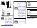
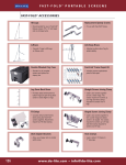
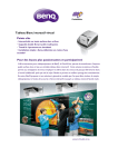
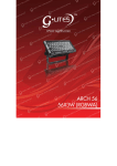
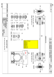
AC Motor Installation Instructions
step of motor installation
【Characteristic】
☺Meet for E-class insulation of UL
☺Can be protected while over-temperature.
☺ Work voice is less than 43dB.
☺ Precision mechanic travel setting.
☺In-phase transmission so speed invariable.
☺Can be used for drapery and canopy.
☺Can be used with straight and curve track.
【Specification】
Rated voltage:
Rated power:
Rated torque:
Rated speed:
Insulation class:
Protection class:
Work method:
Main motor:
Secondary motor:
Track length:
1
AC220V 50Hz
45W
1.2N.m
88.6r/min
E
IP41
S3
800-45A
800-45B (the secondary motor need not
setting the travel, but it should be used
with the main motor.)
15meter max
【General Layout】
Single motor drapery system
Tandem motor drapery system
800-45A
800-45A+800-45B
Drapery weight (Kg)120
Make the output axis aim at the driver unit and push it,
then rotate the motor to the position where buckle is parallel
to the side of driver unit.
2
Rotate the motor to the position that buckle is straight to
the side of driver unit.
3
Push the lock buckle into the driver unit.
KM45A+KM45B
step of motor disassembly
60
KM45A
4
8
Press the lock buckle
12
16 track length (m)
Single motor canopy system
800-45A
Tandem motors canopy system 800- 45A+ 800- 45B
Four motors canopy sysytem
800- 45A+ 800- 45B*3
Canopy weight ( Kg) 60
User Manual
3
6
9
12 track length (m)
-1Thanks for your choice. To insure you can use the product
correctly, firstly, please read the manual carefully.
1
2
3
4
5
KM45A+KM45B*3
【Installation】
■Assemble the track system before you install the motor.
Use the screwdriver press the lock buckle and pull it, then
rotate the motor to the position where buckle is parallel to the
side of driver unit, then pull down the motor.
-2【Connection】
Single motor system
Connection method
Tandem motors system
Connection method
6
White
5
Gray
4
Y/G
3
Brown
2
Black
1
Green
Empty
Empty
L
N
6
White
Empty
5
Gray
Empty
4
Y/G
3
Brown
2
Black
1
Green
again, then pull the button A and let the
travel setting pole to Button A. Up to
now, the A travel setting is finished.
And you are ready for travel setting of
Button B
KM45B
6
White
5
Gray
-3-
control
4
Y/G
3
Brown
2
Black
1
Green
3
Push the travel setting pole to
Button A, then press the button B
and rotate it to the position where
the switch (red, white, and red
round rings) is connected with their
small holes together in a line and
turn it clockwise for two or three
rounds and then running the motor
by receiver. While the glider is on
the position where you want it stop
(reached the either end of the
track), you quickly stop the motor
by receiver and then turn the switch
counter-clockwise to the position
where the switch (red, white, and
red round rings) is connected with
their small holes together in a line
once again, then pull the button B
and let the travel setting pole to the
middle between Button A and
Button B. Up to now, the B travel
setting is finished.
L
N
control
【Travel setting】
■Before travel setting, you should finished the track and motor
assembly.
■If the motor is disassembly, you should setting the
travel again.
1 Remove the travel setting
travel setting cover
Button A travel setting
2
The travel settin pole
Button B travel setting
Button A travel setting
Push the travel setting pole to
Button B, then press Button A and
rotate it to the position where the
switch (red, white, and red round
rings) is connected with their small
holes together in a line and turn it
clockwise for two or three rounds and
then running the motor by receiver.
While the glider is on the position
where you want it stop (reached either
end of the track), you quickly stop the
motor by receiver and then turn the
switch counter-clockwise to the
position where the switch (red, white,
and red round rings) is connected with
their small holes together in a line once
4 Travel setting inspection
Middle
Running the motor and look the stop
position is right or not. If have error,
repeat the step 2 and step 3.
5
If the travel setting is ok,
fixing the cover with three screw.
Button B travel setting
Travel setting finished
-4【Malfunction analyses】
phenomena
analyses
No travel setting
No power supply
No working
Controller
failure
belt
running
suffocate
Drape over load
Librations
Stop not on
the right
position
Power supply is
not right
Travel
setting
wrong
Motor had been
disassembly
operation
Travel setting again
Check the wire connection
Instead or maintain the
controller
Check the track system
check the system is
suitable or not
Check the wire connection
Travel setting again
Travel setting again
If the malfunction can not be solved or have some other
malfunction, please contact with the agent.
-5-