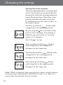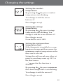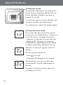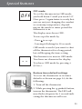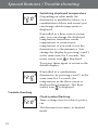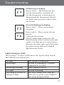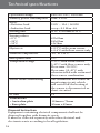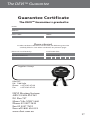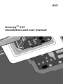
1
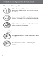
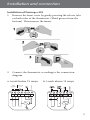
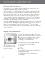
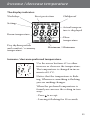
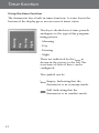
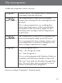
AUS
DeviregTM 535
Installation and user manual
1
Congratulations with…
... your DEVI floor heating system
Your property has been installed with a DEVI heating system.
DEVI is Europe’s leading floor heating manufacturer, with over
45 years experience. We are confident that you will be satisfied
with your new system.
DEVI brings you…
An Invisible heating solution - A concealed heat source opens
up greater opportunities for decorating and furnishing.
Optimum comfort - DEVI brings you the luxury and comfort
of a warm floor as well as a pleasant room temperature. Floor
heating is the most comfortable type of heating because it
is based on the fact that warmth travels upwards; pleasant
warmth for your feet, body and head.
Low running costs – Thanks to the precise DEVI thermostat
and the placement of the heating elements right under the
floor surface the heat can be controlled optimally in order for
you to have the comfort you desire with minimal energy use.
Moreover electric floor heating and ceiling heating is practically
maintenance free, in total keeping down the running costs.
A long lasting solution - We back-up our floor heating solutions with a ten year guarantee on all our mats and cables, and
a two year warranty on our thermostats. Practically speaking
you can count on DEVI heating cables and mats lasting as long
as the house in which they are installed – and that is without
having to maintain them.
Hygiene - As DEVI produces only very gentle air circulation,
the amount of travelling dust particles is reduced considerably;
a great relief for people with allergies or asthma. There are also
no dangerous fumes such as carbon monoxide generated by the
system.
2
Table of content
Table of content
Install & configure the thermostat . . . . . . . . . . . . . . . . . . . . . . . . 4
Placement of DeviregTM 535 . . . . . . . . . . . . . . . . . . . . . . . . . . . 4
Installation of DeviregTM 535 . . . . . . . . . . . . . . . . . . . . . . . . . . 5
Choose sensor combination . . . . . . . . . . . . . . . . . . . . . . . . . . 6
Configuration - Max. floor temp . . . . . . . . . . . . . . . . . . . . . . 8
User’s guide to DeviregTM 535 . . . . . . . . . . . . . . . . . . . . . . . . . . 10
Introduction . . . . . . . . . . . . . . . . . . . . . . . . . . . . . . . . . . . . . . 10
Display, icons and buttons . . . . . . . . . . . . . . . . . . . . . . . . . . . 10
Increase / decrease preferred temperature. . . . . . . . . . . . . . 11
Using the timer function . . . . . . . . . . . . . . . . . . . . . . . . . . . . 12
Settings . . . . . . . . . . . . . . . . . . . . . . . . . . . . . . . . . . . . . . . . . . . 14
Setting the time . . . . . . . . . . . . . . . . . . . . . . . . . . . . . . . . 17
Setting the weekday . . . . . . . . . . . . . . . . . . . . . . . . . . . . . 17
Setting the timer periods . . . . . . . . . . . . . . . . . . . . . . . . 18
Setting the comfort temperature . . . . . . . . . . . . . . . . . . 19
Setting the savings temperature . . . . . . . . . . . . . . . . . . 19
Setting the minimum floor temperature limit . . . . . . . 19
Special features . . . . . . . . . . . . . . . . . . . . . . . . . . . . . . . . . . . . 20
Childproof mode . . . . . . . . . . . . . . . . . . . . . . . . . . . . . . . 20
Frost protection mode . . . . . . . . . . . . . . . . . . . . . . . . . . 20
OFF mode . . . . . . . . . . . . . . . . . . . . . . . . . . . . . . . . . . . . . 21
Restore timer default settings . . . . . . . . . . . . . . . . . . . . . 21
Switching displayed temperature . . . . . . . . . . . . . . . . . 22
Trouble shooting . . . . . . . . . . . . . . . . . . . . . . . . . . . . . . . . . . . 23
Technical Specifications . . . . . . . . . . . . . . . . . . . . . . . . . . . . . . . 24
The DEVITM Guarantee . . . . . . . . . . . . . . . . . . . . . . . . . . . . . . . . 25
3
Install & configure the thermostat
Placement of DeviregTM 535
When DeviregTM 535 is used as a room sensor,
installation height should typically be between
80-150 cm.
In wet rooms it should be installed on an even
surface, according to local building regulations.
At least 50 cm away from windows/doors that
will be left open occasionally.
Not on a wall where it will be subjected to direct
sunlight.
Not on the inner side of a wall facing the
outside.
4
Installation and connection
Installation of DeviregTM 535
1. Remove the front cover by gently pressing the release tabs on both sides of the thermostat. (Third groove from the
bottom). Then remove the frame.
2. Connect the thermostat according to the connection
diagram
Max.Load
15 A
NL
N
N
LOAD
L
L
LOAD
b. Loads above 15 amps
NO CONNECT
Mains
180-250V~
Sensor
a. Loads below 15 amps
NTC
5
Choose sensor combination
3.
Choose sensor combination
When installing the Devireg™ 535 you need to choose the
type of heating and thus which sensors should be used.
You have three options:
Comfort heating: Constant temperature on the floor in
bathrooms and other rooms where a comfortable warm surface is required.
Install the Floor sensor and choose only the Floor sensor.
Total heating: Control of room temperature in living
rooms etc. Install the Floor sensor and choose both Floor
sensor and Room sensor. Also recommended for ceiling heating, with the floor sensor located on top of the plasterboard, on or under the blank, unheated edge of one foil.
Ensure that the sensor is not in direct contact with any part of the metallic heating element.
No floor sensor: A floor sensor is not present, and cannot
be installed. Choose Room sensor.
Be aware that temperature control is less accurate without
the floor sensor.
DEVI recommends that a floor sensor is always installed.
Do not use DeviregTM 535 without a floor sensor when
the heating element is installed on or beneath wooden
surfaces and other surfaces sensitive to temperature!
6
Configuration - sensor
Selection of sensor type
Power on the thermostat.
With the front off, with a small screwdriver, pencil, or needle press the
installation button.
Select the sensors to be used for the
heating system:
DeviregTM 535 is able to use two
sensors:
- a built-in room sensor
- an external sensor to be placed in
the floor.
This gives 3 options:
floor sensor.
room sensor.
both room and floor sensor.
The default is
To change this setting, press • and use
the arrow buttons ∆∇ to select your
choice. Press • to accept your choice.
If you have selected room sensor only,
the installation procedure is complete.
Press installation button to accept.
(Go to page 9)
If you have selected floor sensor or a
combination of room- and floor sensor press ∆∇ for the next setting.
7
Configuration - Max. floor temp.
Maximum floor temperature
When selecting either floor sensor
or
floor and room sensors, next
screen is maximum floor temperature.
Default setting is 35°C.
To change this setting, press • and use
the arrow buttons ∆∇ to select your
choice. Press • to accept your choice.
If you have selected a combination of
room and floor sensor, the installation
procedure is complete.
Press installation button to accept.
(Go to page 9)
If you have selected floor sensor only
press ∆∇ for the next setting.
Notice:
The floor temperature is measured where the sensor is placed.
The temperature of the bottom of a wooden floor can be up
to 10 degrees higher than the top. Floor manufactures often
specify the max. temperature on the top surface of the floor.
Please contact your floor supplier for maximum surface temperature. For ceiling heating, the maximum floor temperature
should be set to 45°C in accordance with the plasterboard
manufacturer’s recommendations.
8
Configuration - Scale
Scale
If you select DeviregTM 535 to only use
a floor sensor, mode , you have to
select the display type. The choice is
either numerical scale 1-6 or Celcius
scale 5° to 45°.
Default is Celcius scale. When selecting Celcius, the display will show the
actual temperature at the floor sensor.
To change this setting, press • and use
the arrow buttons ∆∇ to select your
choice.
Press • to accept your choice.
The installation procedure is now
finished.
You can use the ∆∇ for going back or
forward through the settings.
Otherwise:
Press the installation pinhole to exit
installation mode.
4. Put the frame and front back on.
9
User’s guide to DeviregTM 535
DeviregTM 535 Introduction
DeviregTM 535 is a simple timer temperature controller, specially designed for floor heating systems.
The DeviregTM 535 will measure the radiant comfort from the
floor or ceiling combined with the comfort from the air temperature in the room to off set the outside weather condition.
This means that as soon as you have set your DeviregTM 535
at your desired comfort temperature, DeviregTM 535 will then
automatically adjust the heating to meet your comfort levels,
regardless of changing weather conditions.
Even the programming of economy temperatures (i.e. lowering
of temperature during the night and when you are out of the
house) is very simple. Just tell the DeviregTM 535 when you
want the comfort temperature, and the DeviregTM 535 will take
care of the rest.
Display, icons and buttons
This is the standard display. The currently measured temperature is shown.
is shown to symbolize that current
temperature is displayed, i.e. unit
working as a thermometer.
The thermostat can
be turned On / Off
with the switch.
The thermostat is operated with the
3 buttons below the display.
∇ down
∆ up
• select
Two pinhole buttons are available for
dedicated features
Childproof. Locks all buttons.
Settings.
10
Increase / decrease temperature
The display indicates:
Weekdays
Frost protection
Childproof
Settings
Actual temperature is displayed
Room temperature
Day rhythm periods
and comfort / economy
temperature
Floor
temperature
Maximum / Minimum
Increase / decrease preferred temperature.
Use the arrow buttons ∆∇ to either
increase or decrease the temperature.
The temperature is changed in increments of 0.1°C.
Notice that the temperature is flashing. Whenever something is flashing
you are making changes.
When the preferred temperature is
found you can save the setting in two
ways
- Press • to accept
- Leaving it flashing for 10 seconds.
11
Timer function
Using the timer function
Night
Evening
The day is divided into 4 time periods
analogous to the typical day programming pattern:
Day
Morning
The thermostat has a built-in timer function. A status bar in the
bottom of the display gives an overview of timer status.
- Morning
- Day
- Evening
- Night
as
These are indicated by the
shown in the picture to the left. The
start time of each of these can be
configured.
The symbol can be:
12
Empty: Indicating that the
thermostat is in economy mode.
Full: Indicating that the
thermostat is in comfort mode.
The 4 programs
4 different programs can be selected
Program 1
Manual mode. The temperature is maintained
constantly 24 hours all week.
Program 2
The temperature is lowered to economy
temperature during the day and night period
all week.
P2 is a day program for e.g. working days
where the temperature is decreased during
the middle of the day and at night. In the
morning and evening comfort temperature
is preferred.
Program 3
The temperature is lowered to economy temperature during the night period all week.
P3 is a program for days at home where comfort temperature is preferred during the day
and a savings temperature at night.
Program 4
A week program where:
Mon – Fri: Program 2 and
Sat – Sun: Program 3
P4 is a week program with Monday-Friday as
workdays and Saturday-Sunday as days off.
The top 7 bars indicate Monday through Sunday. On week days timer program 2 is used
and in weekends timer program 3.
Factory setting is Program 1. Manual mode.
13
Factory settings
The factory setting of the timer is:
Floor
sensor only
Temperature:
Comfort
25°C
Economy
5°C
Periods – Day rhythm:
Morning
Day
Evening
Night
Room
sensor only
Floor and
Room sensor
21°C
17°C
21°C
17°C
06:00-08:00
08:00-16:00
16:00-22:30
22:30-06:00
You can use the above as it is, or you can change the settings to
match your day pattern.
See the chapter Settings – setting the timer periods, page 18.
Changing timer program
To change the program:
(Remember, you need to set the time
in advance, p.17)
Keep the • button pressed for 2 seconds.
The actual program starts to flash. It is
now possible to change the program
by using the buttons ∆∇
Press • to accept
14
Changing timer program
During the timer programs, P2, P3,
and P4, the flashing
indicates the
actual time period.
In program 4 the actual day is also
shown.
Using the arrow buttons ∆∇ in timer
mode, is somewhat different from
manual mode.
If you increase/decrease the temthis
perature in a savings period
change only applies to this current
period, not any future savings periods.
You might use this if you are eg. working at home in timer program 4.
If you increase/decrease the temperature in a comfort period
this
change applies to all future comfort
periods, until changed again. From the
perspective that you are fine tuning
the comfort temperature.
15
Settings overview
Settings
All settings are under
following:
the settings menu. Here you set the
- Time
- Weekday
- Timer periods configuration
(Morning, day, evening and night)
- Comfort temperature
- Savings temperature
- Min. floor temperature limit
(Only when combination of room
and floor sensor is installed).
16
Changing the settings
You enter the settings by pressing the
pinhole with a small screw driver,
pencil, or needle, the display now
changes from temperature to time
display.
By using the arrow buttons ∆∇ you
move one way or the other in the
menu.
Setting the time
By pressing the • the hours start flashing, indicating you can change them
with the arrow buttons ∆∇
Press the • again to change the
minutes.
Battery Backup: The current time and
day is kept for 80 days if mains supply
is off. All other settings are stored
permanently. Initially mains supply
the thermostat for 15 hours to fully
charge the battery.
Setting the weekday
By pressing the • the weekday starts
flashing, indicating you can change it
with the arrow buttons ∆∇
Press the • to accept
17
Changing the settings
Setting the timer periods
When programming the starting times
of the 4 periods keep in mind that the
thermostat will start heating/stop heating at the given time. Therefore some
periods should start and end before,
to compensate for the time it takes to
heat up or down.
The first period bar
flashes indicating this is the morning period.
By pressing the • the start time of the
period starts flashing. You change it
with the arrow buttons ∆∇ in increments of 15 minutes.
Press the • to accept
The second period bar
flashes
indicating this is the day period.
Setting it in the same way.
The third period bar
flashes indicating this is the evening period.
Setting it in the same way.
The fourth period bar
flashes
indicating this is the night period.
Setting it in the same way.
Note! When setting the time periods you cannot step backward
to the previous time period, until the last one is set. This is to
ensure that the periods do not overlap.
18
Changing the settings
Setting the comfort
temperature
By pressing the • the preset comfort
temperature starts flashing.
You change it with the arrow
buttons ∆∇
Press the • to accept
Setting the savings
temperature
By pressing the • the preset savings
temperature starts flashing. You
change it with the arrow buttons ∆∇
Press the • to accept
It can also be set to OFF.
Setting the minimum floor
temperature limit
If the thermostat is installed as a combination of room and floor sensor the
minimum comfort temperature on the
floor can be selected.
Setting this will overrule any other set
point as you always want e.g. 20°C at
the floor sensor
--.-° means that the function is
disabled.
By pressing the • the preset minimum
floor limit temperature starts flashing.
You change it with the arrow ∆∇
Press the • to accept
19
Special features
Childproof mode
You disable all buttons in child proof
mode by pressing the pinhole button
below with a small screw driver,
pencil, or needle.
A lock now appears in the display and
all other buttons are locked now.
To unlock press the lock symbol again
Frost protection mode
To set the thermostat in frost protection mode, you hold down ∇ until you
reach the lowest setting. Now press
∇ again to verify that you are not just
changing the comfort or economy
temperature, depending on the mode
or timer period the thermostat is in.
The frost icon now appears and 5.0°
flashes.
You accept the mode by
- Press • to accept
- Leaving it flashing for 10 seconds.
The thermostat is now in frost protected mode. Actual temperature is
shown.
You leave frost protection mode by
pressing ∆ (0.5sec).
20
Special features
OFF mode
To set the thermostat in OFF mode,
you hold down ∇ until you reach 5.0°.
Now press ∇ again twice to verify that
you are not just changing the comfort
or economy temperature, depending on the mode or timer period the
thermostat is in.
The display now shows OFF.
You accept the mode by
- Press • to accept
- Leaving it flashing for 10 seconds.
OFF mode is used if you want to shut
off the thermostat for a long period,
but still keeping the time setting.
The thermostat is now in OFF mode.
Two lines are shown in the display.
You leave OFF mode by pressing ∆
(0.5sec).
Restore timer default settings
To reset the thermostat to its timer
defaults as shown on page 14, do the
following:
1. Turn off the thermostat
2. While pressing the pinhole button,
turn on the thermostat. The LED will
now flash red/green for 1 second indicating the thermostat will reset.
21
Special features / Trouble shooting
Switching displayed temperature
Depending on what mode the
thermostat is installed as (floor, or a
combination of floor and room) you
can change which temperature is
displayed.
If installed as a floor sensor system
only, you can change the displayed
temperature from floor sensor
temperature to room sensor
temperature, if you wish to use the
thermostat as a thermometer. You
change the display by pressing ∆ and ∇
at the same time for 2 seconds. The
room sensor icon is displayed.
You press them again to return to the
default display.
If installed as a combination
thermostat, by pressing ∆ and ∇ at the
same time for 2 seconds, the
temperature in the floor sensor is
displayed for 2 minutes. The floor
sensor icon is displayed.
Trouble shooting
Clock symbol flashing:
Time settings were lost due to power
cut.
The thermostat resumes to manual
mode.
22
Trouble shooting
E4 flashing in display:
Error code 4 – The thermostat has
overheated and has switched off
Let the thermostat cool for period.
Then switch the thermostat off and
on. If the error persists contact your
electrician.
E5 or E6 flashing in display:
Error code 5 - Floor sensor short
circuited
Error code 6 - Floor sensor disconnected
Call your electrician.
Check connections, if they are OK,
then disconnect the 2 sensor wires and
connect an ohm meter to sensor wires.
Measure the ohm value and check with
the values in the table in Technical
Specifications below.
Light Indications (LED)
The DeviregTM 535 has a LED above the 2 pole safety switch.
The LED has five indications:
No light
Green light
Green light flashing
Red light
Switching between red
and green light
The system is turned off.
System is standing by, set point
temperature reached
Floor sensor is defect
System is heating
The floor temperature limit prevents the set point room temperature from being reached.
23
Technical specifications
Operation voltage
Standby power consumption
Relay:
• Resistive load
• Inductive load
Sensing unit
Sensing values:
• 0°C
• 20°C
• 50°C
Hysteresis
180-250 VAC, 50/60 Hz
Max. 0.30W
230V ~ 15A / 3450W
cos φ= 0.3 Max. 4A
NTC 15 kOhm at 25°C
IP class
42 kOhm
18 kOhm
6 kOhm
± 0.2°C with room sensor,
± 0.4°C with floor sensor only
-10° to +30°C
5°C
5-35°C with room sensor,
5-45°C with floor sensor only.
Floor max. 20-50°C.
Floor min. 10-45°C only
when installed with room and
floor sensor combination
The thermostat has a built-in
monitoring circuit, which
will switch off the heating if
the sensor is disconnected or
short-circuited
31
Dimensions:
• Australian plate
• Euro plate
118mm x 79mm
85mm x 85mm
Ambient temperature
Frost protection
Temperature range
Sensor failure monitoring
Disposal Instruction
Equipment containing electrical components shall not be
disposed together with domestic waste.
It must be collected separately with other electrical and
electronic waste according to local legislation.
24
The DEVI TM Guarantee
You have purchased a DEVI heating system which we are sure
will serve to improve the comfort and economy of your home.
DEVI provides a complete heating solution with deviflex™
heating cables or devimat™ heating mats, Devireg™ thermostats
and devifast™ fixing strips. Should you, against all expectations,
experience a problem with your DEVI heating system, you will
find that DEVI, whose products are manufactured in Denmark
and sold throughout the European Union, is subject to the
standard regulations pertaining to product liability as specified
in EU directive 85/374/CEE as well as all applicable legislation
in the individual countries on the following conditions: DEVI
offers a 10-year Warranty on all deviflex™ heating cables and
devimat™ heating mats, and a 2-year Warranty against material
defects and production defects in connection with any other
DEVI products.
The guarantee shall be valid only if the WARRANTY CERTIFICATE is completed correctly and in accordance with the
instructions, and provided the fault is inspected by or submitted
to DEVI or an authorised DEVI dealer. Please note that the
WARRANTY CERTIFICATE must be completed in English or
local language.
DEVI shall undertake any repair free of charge or supply the
customer with a new unit. Repairs shall be carried out at no
further cost to the customer. In the case of faulty Devireg™
thermostats, DEVI reserves the right to repair the unit free of
charge and without any unreasonable delays for the customer.
The DEVI Warranty shall not cover installations that have been
carried out by non-authorised electricians, faults which arise as
a result of misuse by other suppliers, damage caused by third
parties, incorrect installations or consequential damage. All
25
work will be invoiced in full if DEVI is required to inspect or
repair faults that have arisen as a result of any
of the above.
The DEVI Warranty shall not extend to equipment which has
not been paid in full. DEVI will, at all times, provide a rapid,
effective and honest response to all queries and reasonable
demands from our customers. The above Warranty covers
product liability only, while purchases are subject to national
legislation.
26
The DEVI TM Guarantee
Guarantee Certificate
The DEVITM Guarantee is granted to:
Name:
Address:
Postal code:
Phone:
Please observe!
In order to obtain the DEVITM Guarantee, the following must be
carefully filled in. See other conditions on previous page.
Electrical Installation by:
Installation date:
Type of thermostat:
Production code:
Suppliers Stamp:
DEVI A/S
DK • 7100 Vejle
Phone +45 76 42 47 00
Fax
+45 76 42 47 03
DEVI Heating Systems
ABN 39 898 434 262
PO Box 707
Mona Vale NSW 1660
Phone 02 9997 2811
Fax 02 9997 7852
Freecall 1800 636 091
www.devi.com.au
27
Article: 08095851
Version: 01.02
28