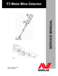
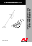
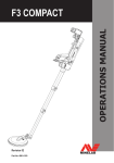
1
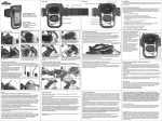
FIELD SERVICE MANUAL F1A4 Metal Mine Detector NSN 6665-66-142-9741 LEVEL 1 MAINTENANCE Date: 1st June, 2005 F1A4 Field Service Manual – Level 1 Maintenance Page 2 F1A4 Field Service Manual – Level 1 Maintenance WARNING THIS DOCUMENT CONTAINS MINELAB ELECTRONICS LIMITED RIGHTS TECHNICAL DATA OR RESTRICTED RIGHTS DATA OR BOTH. Minelab Electronics This work is copyright. Apart from any use as permitted under the Copyright Act 1968, no part may be reproduced by any process without written permission from Minelab Electronics 118 Hayward Avenue, Torrensville South Australia.5031 CONTENTS SECTION PAGE 1. Introduction ...................................................................................................................5 1.1 Levels of Maintenance ............................................................................................5 1.2 How to use this Manual ...........................................................................................5 Level 1 Maintenance ..............................................................................................................6 2. Mechanical and Functional Testing of the F1A4 ................................................................7 2.1 Mechanical Testing .................................................................................................7 2.2 Functional Testing...................................................................................................8 3. Maintenance Procedures .................................................................................................11 3.1 Camlock Repair Procedures .................................................................................11 3.2 Replacing the Handle Assembly............................................................................14 3.3 Replacing the Handgrip.........................................................................................15 3.4 Replacing the Coil .................................................................................................15 F1A4 Field Service Manual – Level 1 Maintenance 1. INTRODUCTION This manual is intended to instruct service technicians in functional testing and Level 1 maintenance of the F1A4 mine detector. All sub-assemblies of the F1A4 can be replaced without the need for adjustment or calibration. This service manual includes all Level 1 maintenance procedures, including functional testing and troubleshooting. 1.1 LEVELS OF MAINTENANCE Levels of maintenance for the F1A4 comprise: Level 1: Level 1 maintenance includes repair and/or replacement of all major components of the detector. This level of maintenance can be conducted at demining field sites or local depots if required. Level 1 maintenance includes full functional testing of the detector and does not require any special test equipment or facilities. Level 2: Level 2 maintenance encompasses Level 1 maintenance plus coil retermination and basic repairs to the F1A4 control box and earset. This level of maintenance requires electronic workshop facilities. Level 3: Level 3 maintenance encompasses Level 1 and Level 2 maintenance, plus control box printed circuit board repair. Level 3 repairs are only conducted at Minelab's repair workshops located in Australia, Ireland and the USA. 1.2 HOW TO USE THIS MANUAL This manual is divided into Level 1 maintenance sections. If doubt exists as to the serviceability or mechanical integrity of the F1A4, turn to Section 2 for a comprehensive mechanical and functional test of the F1A4. If any mechanical component (eg handgrip, coil) of the F1A4 requires replacement, turn to Level 1 maintenance procedures in Section 3, which details all mechanical repairs. All repairs to the F1A4 Control Box, and Coil retermination procedures require Level 2 Maintenance and should be sent to an accredited Level 2 repair facility. Page 5 F1A4 Field Service Manual – Level 1 Maintenance LEVEL 1 MAINTENANCE Page 6 F1A4 Field Service Manual – Level 1 Maintenance 2. MECHANICAL AND FUNCTIONAL TESTING OF THE F1A4 This section details mechanical and functional testing of the F1A4. Section 2.1 lists all mechanical testing and directs the user to applicable Level 1 repair procedures if any defects are found. Section 2.2 lists functional testing of the F1A4 and will refer the user to the applicable fault finding procedure if a fault is found. A defective component is confirmed using the substitution method, so a complete and fully serviceable F1A4 should be on hand. After any repair to the F1A4, Section 2.2 Functional Testing, must be completed in full to ensure the F1A4 is returned for operational use. 2.1 MECHANICAL TESTING To conduct mechanical testing, unpack and fully assemble the F1A4 (As described in the F1A4 Operations Manual). Ensure the armrest is fitted, control box is mounted on the shaft and good batteries are used. During assembly: 1. Check that the coil yoke nut and bolt are firmly tightened and that the friction washers are present and in good condition. The coil should be held firmly in position (but moveable) on the yoke. If coil is loose on the yoke check the nut, bolt and friction washers and replace as required. 2. Check that the skid plate is firmly attached, is not worn through or cracked. Replace if required. 3. Check that the upper shaft slides smoothly over the lower shaft and when the camlock is closed the upper shaft stays in position on the lower shaft. If necessary, replace the camlock (Section 3.1). 4. Inspect the Armrest for cracks and other damage. Inspect the armstrap. Check that the armrest slides fully into the upper shaft and is held firmly when the upper camlock is closed. If necessary, replace the camlock (Section 3.1). 5. Check that the control box is firmly attached when the lock pin is fully rotated to the stop. If necessary replace the handle (Section 3.2). 6. Inspect the handstrap and hand grip for wear, and replace if necessary (Section 3.3). Page 7 F1A4 Field Service Manual – Level 1 Maintenance 2.2 FUNCTIONAL TESTING This section details functional testing of the F1A4. It should be used to confirm serviceability of an F1A4 before it is returned to the field for use and whenever doubt exists about the serviceability of an F1A4. The F1A4 must pass all these tests to be considered serviceable. Remedial action is included for repair if required. If remedial action is completed (ie the F1A4 is repaired using these procedures), the full functional test should be repeated from Section 2.2.1. A Ground Balance (GB) Test Piece is required to properly test the F1A4. This is needed to simulate mineralised or “noisy” ground and ensure correct F1A4 Ground Balance operation. The GB Test Piece can be a local piece of mineralised ground (hot rock or a fired tile) that produces a response from the F1A4. Procedure: Ensure the coil connector ‘clicks’ in to the socket. If the coil plug does not ‘click’ in, replace the coil plug washer, if the coil plug still does not ‘click’ in, send the coil to an accredited F1A4 Level 2 maintenance workshop. Note: The Coil must not be near any metal objects, and the technician must not wear any rings, bracelets, or watches during this procedure. 2.2.1 Initial Power On Test Switch the F1A4 on to the Search position. The detector should take six seconds to run through the start up routine, comprising four rising tones followed by a continuous background threshold tone. F1A4 target response is indicated by a clear change in the threshold tone. The amount of change is dependent on the size of the target (larger target – louder response) and the distance from the coil to the target (closer to coil – louder response). If the correct tones or threshold are not heard the faulty control box (or battery carrier) should be replaced or the F1A4 should be sent to an accredited F1A4 Level 2 maintenance workshop. 2.2.2 Sensitivity Testing Hold the Test Piece Mine Detector in one hand, with the end containing the target away from the Coil. Move the Test Piece Mine Detector towards the centre of the coil until it lightly touches the centre of the coil and then move it sideways off the coil (the Test Piece Mine Detector should be moved slowly and smoothly during this procedure). A soft but distinct change in the threshold tone should be heard. P0263-B If a response is not heard replace the faulty Control Box (or Coil, see Section 3.4) or the F1A4 should be sent to an accredited F1A4 Level 2 maintenance workshop for repair. Page 8 F1A4 Field Service Manual – Level 1 Maintenance 2.2.3 Ground Balance Testing Note: The F1A4 Control Box will memorise its last Ground Balance settings when switched off and then on again. If a Control Box/Coil combination has been previously balanced to the GB Test Piece, on re-testing, a response to that hot rock will not be heard again. The same Control Box/Coil combination must be rebalanced with a GB Test Piece with different characteristics before re-testing. (If a suitable GB Test Piece is not available, a piece of ferrite or local ground around the workshop may suffice.) While holding the Off/Search/Balance switch in the Balance position, move the GB Test Piece up and down, approximately 25 to 100 mm from the Coil. Note: For the first five seconds when the Off/Search/Balance switch is switched to the Balance position, the F1A4 will ground balance at a fast rate, after this time the F1A4 will continue to balance but at a much slower rate. Consequently, if the F1A4 has not completely balanced out the GB Test Piece within five seconds, release the Off/Search/Balance switch to the Search position and reselect the Balance position. The F1A4 should initially detect the GB Test Piece (a change of threshold tone will be heard) as the GB Test Piece is moved to and from the Coil. The F1A4 will then become “balanced” to it, i.e. the F1A4 threshold will remain stable as the GB Test Piece is moved to and from the Coil. To confirm that the F1A4 has ‘balanced’ correctly: 1. Release the Off/Search/Balance switch so that it returns to the Search position. 2. Move the GB Test Piece as described above and confirm that there is no further response from the F1A4. 3. If a response is still heard, check that there is no metal on the technician or the GB Test Piece and repeat the test. If the F1A4 still responds to the GB Test Piece, the faulty Control Box or Coil, (Section 3.4) should be replaced or the F1A4 should be sent to an accredited F1A4 Level 2 maintenance workshop for repair. Page 9 F1A4 Field Service Manual – Level 1 Maintenance 2.2.4 Coil Connector Test Loop the coil cable and hold against side of the control box, approximately 250mm from the coil connector. Grasp the coil cable 75mm from the coil connector and gently turn 30 degrees side to side, listening for a change of threshold. If there is a noticeable threshold change (ie similar in volume to test piece threshold change), the Coil should be replaced (Section 3.4) or the F1A4 should be sent to an accredited F1A4 Level 2 maintenance workshop for repair. 2.2.5 Noise Cancel Test Momentarily press the NOISE CANCEL button. The F1A4 should immediately “beep”. After 70 seconds the F1A4 should “beep” four times: BEEP BEEP BEEP BEEP If the correct tones are not heard the faulty Control Box should be replaced or the F1A4 should be sent to an accredited F1A4 Level 2 maintenance workshop for repair. 2.2.6 Audio Reset Test Momentarily press the AUDIO RESET button. The F1A4 should immediately BEEP. After 3 seconds the F1A4 should give five “high / low” beeps: BEEP BEEP BEEP BEEP BEEP The threshold tone level should now be set at the correct operating level (ie just audible). If the correct tones or threshold level are not heard the faulty Control Box should be replaced or the F1A4 should be sent to an accredited F1A4 Level 2 maintenance workshop for repair. 2.2.7 Earset Test 1. 2. 3. Connect the Earset to the Control Box and ensure that the threshold tone is audible at the earphone. If a volume control is fitted, ensure that it operates correctly. If the Earset does not operate correctly it should be replaced or the F1A4 should be sent to an accredited F1A4 Level 2 maintenance workshop for repair. Page 10 F1A4 Field Service Manual – Level 1 Maintenance 3. MAINTENANCE PROCEDURES This section details mechanical maintenance procedures and covers the following: 1. Camlock repair procedures (Section 3.1) 2. Handle replacement procedures (Section 3.2) 3. Hand grip replacement procedure (Section 3.3) 4. Coil replacement procedure (Section 3.4) 3.1 CAMLOCK REPAIR PROCEDURES This procedure details the dismantling and re-assembly of the Camlocks fitted to the Upper Shaft of the F1A4. This is only necessary when a Camlock becomes damaged or worn. The F1A4 uses Camlocks in three locations – Upper Camlock locks the armrest into the Upper shaft, Lower Camlock locks the lower shaft into the Upper shaft and the Handle camlock locks the Handle onto the Upper shaft. Camlock kits are available to renew their locking capability - they are easily and cost effectively serviced using the following procedures. These procedures should also be used to remove and refit camlocks when replacing a coil. Procedure: fitted) Remove the Control Box, Lower shaft, and Armrest from the Upper Shaft (if Identify the Camlock to be replaced or serviced: Note: The Upper and Lower Camlocks use different Pressure Blocks. Refer to the figure above to ensure that you have the correct service kit for the Camlock to be serviced. Each kit contains all the components for servicing a particular Camlock: 1. 8008-0012 Service Kit Camlock Upper 2. 8008-0013 Service Kit Camlock Lower 3. 8008-0014 Service Kit Camlock Handle Page 11 F1A4 Field Service Manual – Level 1 Maintenance 3.1.1 Servicing the Upper and Lower Camlocks 1. Knock out Camlock Pivot Pin with the 3 to 3.5mm punch. 2. Remove Cam Lever from the Camlock Body. 3. Remove Pressure Block from the Camlock Body. 4. Slide the Camlock Body from the shaft. 5. Assembly is the reverse of the dismantling procedure, with attention to the following: 1. use only new components from the appropriate Camlock Service Kit, 2. press the Stainless Steel Wear Plate firmly into the Pressure Block, and 3. ensure that the correct Pressure Block is used at the correct end. Note: The Pressure Block End Views (at right) should help the identification process. Page 12 F1A4 Field Service Manual – Level 1 Maintenance 3.1.2 Servicing the Handle Camlock 1. Knock out Camlock Pivot Pin with the 3 to 3.5mm punch and Remove the Cam Lever. 2. Remove the Stainless Steel Wear Plate, 3. Assembly is the reverse of the dismantling procedure, with attention to the following: 1. Use only new components from the Handle Camlock Service Kit. 2. Ensure that the Stainless Steel Wear Plate is correctly seated in the Handle Moulding until the Cam Lever is installed. The Cam Lever holds the Wear Plate in place. Page 13 F1A4 Field Service Manual – Level 1 Maintenance 3.2 REPLACING THE HANDLE ASSEMBLY 1. Remove the Control Box, Lower Shaft and Armrest (if fitted) from the Upper Shaft. Remove the Upper Camlock as described in Section 3.1. 2. 3. Release the Camlock Handle and slide the old Handle off the shaft. 4. Slide the New Handle onto the shaft ensuring correct orientation. 4. Refit the new Upper Camlock as described in Section 3.1. Page 14 F1A4 Field Service Manual – Level 1 Maintenance 3.3 REPLACING THE HANDGRIP 1. 4. Remove the hand strap from the handle (refer to the ‘F1A4 Operations Manual if required). Cut the foam hand-grip down its length and remove it. Using water, wet the handle and the foam and slide the foam hand-grip onto the handle. Refit the hand strap. 3.4 REPLACING THE COIL 2. 3. 3.4.1 To Remove a Coil: 1. 2. 3. 4. 5. 6. 7. 8. Carefully remove the dust cap from the Coil Plug. Remove the Upper Camlock Assembly (Section 3.1) and open the Lower Camlock. (This will allow the Coil Connector to easily pass through the Upper Shaft.) Withdraw the cable through the Upper Shaft. Starting from the upper end, pull the cable from the channel in the Lower Shaft and then from the cable clamp in the yoke. Remove the black wing-nut and bolt from the Coil-to-Shaft joint. Remove the friction washers from the Coil. Remove the Skid Plate. The Skid plate can be levered from the Coil with a flat bladed screwdriver, taking care not to damage the Coil or the Skid Plate. The coil is now free from the Lower Shaft. 3.4.2 To Refit a Coil: 1. 2. 3. 4. 5. 6. 7. 8. 9. 10. Fit the friction washers to the coil. Ensure that the four legs on each washer are pushed fully into their respective holes. Refit the Skid Plate. Hold the new Coil on a flat surface, position the Lower Shaft correctly around the coil top, insert the nylon bolt and attach the nut. Tighten the nut so that the coil can still pivot, but is not loose. Dampen the cable and cable groove with water. Starting at the lower end of the cable, and with the Shaft at 90° to the Coil face, use your thumbs to press the cable into the cable clamp in the black plastic yoke on the Lower Shaft. With your thumbs, press the cable into the cable groove in the Lower Shaft, ensuring that there is some free play in the cable between the Coil and the cable clamp. (The Shaft should still be at 90deg to the coil). Slide the Connector and cable through the Upper Shaft, starting from the Lower end, (the end with the Camlock still in position). Draw the cable up through the Upper Shaft. Note: The cable is to be drawn through, rather than trying to push it through. Replace the Upper Camlock Assembly (Section 3.1). Refit the dust cap to the Coil plug. (The dust cap should be moistened with a small amount of water to facilitate this step, ensure that no moisture enters the coil plug.) Page 15