1
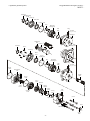
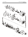
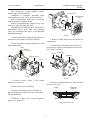
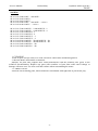
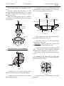
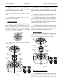
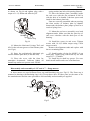
SERVICE MANUAL
Hydraulic Motors type MV…
and MLHV…
Series 1 and 2
2008
Сервизно ръководство
Хидравлични мотори Тип MT…
MLHT…
Dust Seal
Retaining ring
A110
Front Cap
Shaft Seal
O-ring 110x3
Key
Shaft and
Bearing Kit
Plug
Seal
Ring
Washer
(O-ring for SAE)
Housing"C"
Castellated
Nut
Washer
Key
Dust Seal
Housing"W"
Screw
Front Cap
Shaft
Seal
O-ring
114,02x1,78
Key
Shaft and
Bearing Kit
Plug
Seal
Ring
O-ring
113x3
Washer
(O-ring for SAE)
Roll-gerotor
Set
Pin
Cardan
Shaft
O-ring
113x3
Valve
Plate
Valve
Drive
Housing
Balance
Plate
Spring
Washer
O-ring
70x2
Channel
Plate
O-ring
45x2
End
Cover
Pin
Screw
Spacer
Rivet
Check valve
Name
Plate
-2-
Hydraulic Motor type MVS(V)…
MLHVS(V)…
Service Manual
Shaft cap
Seal Ring
O-ring 115x3
Screw M5x30
Front Cap
Cardan
Shaft
O-ring
113x3
Shaft cap
Screw Roll-gerotor
Set
Pin
Seal Ring
O-ring
140x3
Plug
Washer
Flange
(O-ring for SAE)
Cardan
Shaft
O-ring
113x3
Roll-gerotor
Set
Pin
Valve
Drive
O-ring
113x3
Channel
Plate
Valve
Plate
Balance
Plate
Spring
Washer
O-ring
70x2
O-ring
45x2
End
Cover
Pin
Spacer
Screw
Name Plate
Rivet
Check valve
-3-
Service Manual
Hydraulic Motor type MV…
MLHV…
Disassembly
The instructions in this manual concern
motors types MV and MLHV.
Cleanliness is extremely important when
repairing these motors. Work on clean surface!
Before disassembly, drain the oil from the
motor and dry the working bench.
If there is castellated nut, washer or key, they
have to be removed from the shaft.
Although not all drawings show the motor in
disassembly devise (vice with soft clamping
jaws), we recommend the motor to be tightened
during disassembly.
O-ring 113x3
Roll-gerotor
Set
Cardan
Shaft
Fig.2
1. Unscrew the Drain plug with S6 Allen key
and remove the washer (O-ring for MLHV).
7. Remove cardan shaft from the splines of
output shaft.
2. Place the motor in disassembly devise with
output shaft down.
Plug
Washer
8. Turn housing with the shaft up. Unscrew
bolts using a socket wrench. Remove front cover
incl. seals. (see Fig.3).
(O-ring for SAE)
Screw
Front Cap
Housing
End Cover-set
Screw
Fig.1
Fig.3
3. Unscrew screws using a S24 torque
wrench (see Figure 1).
9. Remove carefully dust seal, shaft seal and
O-ring (see Fig. 4).
4. Remove end cover assembly.
Front Cap
series 2
O-ring
5. Remove the roll-gerotor set carefully to
prevent dropping of rollers and rotor from stator.
Do not dismount!
6. Remove O-ring 113х3 from roll-gerotor
groove (see Figure 2).
Shaft Seal
Dust Seal
Fig. 4 (for series 2)
-4-
Service Manual
Hydraulic Motor type MV…
MLHV…
Disassembly
device or two studs M16 placed diametric in
plate holes.
Front Cap
series 1
12. Remove valve drive carefully than
remove disc valve.
Shaft Seal
Dust Seal
13. Turn the end cover with the hole
conversely on a clean soft surface. Knock several
times using a plastic hammer on the rear side. Set
in order the fallen parts apart (see Fig.6).
Fig.4 a (for series 1)
10. Fix Housing in a hydraulic press and push
output shaft with bearing kit out of housing (see
Fig.5).
Note: Replace Output Shaft and bearing kit
as a unit. If not necessary do not dismount the
bearing kit!
14. Remove O-rings 70x2 and 45x2 from the
grooves of the balance plate.
Note: In older versions Cant seals are used
instead of O-rings.
15. Remove the pin using a vice with soft
jaws or pliers knocking on the balance plate and
swivelling it round the pin simultaneously.
PRESS
Check Valve Disassembly (2 psc.):
With an Allen key S5 remove plug and check
valve parts from end cover (see Fig.7).
Fig.5
End Cover Disassembly:
Ball
Guide pin
Spring
Washer Plug
O-ring 113x3
Valve
Plate
Balance
Plate
Fig.7
Spring
Washer
O-ring
70x2
Channel
Plate
O-ring
45x2
End Cover-set
Pin
Spacer
Fig.6
11. Turn the End Cover with the internal hole
upwards. Remove the O-ring. Take the channel
plate up swivelling it slightly. Use corresponding
-5-
Service Manual
Hydraulic Motor type MV…
MLHV…
Disassembly
Seal Kits:
SK 41 5129 7200 for MV… and MVW…
SK 41 5129 7845 for MVS…
SK 41 5129 7865 for MVV…
SK 41 5125 9500 for MV… and MVW…- series 2
SK 41 5125 9100 for MVC…- series 2
SK 41 5123 7240 for MLHV…2 and MLHVW…2
SK 41 5123 7250 for MLHV…4 and MLHVW…4
SK 41 5123 7270 for MLHVS…2
SK 41 5123 7275 for MLHVS…4
SK 41 5123 7490 for MLHVV…2
SK 41 5123 7495 for MLHVV…4
SK 41 5124 8750 for MLHV…2B and MLHVW…2B
SK 41 5124 8770 for MLHV…4B and MLHVW…4B
SK 41 5124 7960 for MLHVC…2B
SK 41 5124 7980 for MLHVC…4B
1. CLEANING:
Wash all parts (except seals) in a weak solvent on carbon base and then degreased.
2. MEASURING AND REPLACEMENT:
Measure all parts and compare their actual dimensions with the nominal ones given in the
technical documentation. Replace any parts with scratches or burrs that could cause leakage or
damage with new ones. Use new seals and washers when reassembling the motor.
3. LUBRICATION:
Lubricate all frictioning parts, which should be reassembled with light film of petroleum jelly.
-6-
Service Manual
Hydraulic Motor type MV…
MLHV…
Reassembly
1 Place the housing in reassembly device
(vice).
Lubricate sealing ring and place it in the
housing. Lubricate bearing surface. Use a press
to install output shaft with bearing kit into
housing (see Fig.8).
Rotate the shaft by hand. The max. moment
of rotation of the shaft with assembled bearing
is 0,25 daNm.
4. Assemble front cover and housing so that
L-H difference ensures clearance of S=0,05÷0,2
mm. If necessary grind the front cover.
PRESS
O.D.>85
Seal
Driver
PRESS
Shaft Seal
Shaft and
Bearing Kit
Dust Seal
Seal
Ring
Housing
Fig.8
Assemble Front Cover and Housing
(Fig.9)
Front Cap
O.D.<60
Fig.10
5. Place shaft seal in the Front cap and firmly
push with Seal driver (see Fig.10).
6. Turn the front cap on 180o and carefully
press dust seal into place
Important: Lubricate shaft seal and dust seal
with light film of clean petroleum jelly.
7. Install the front cap incl. assembled seals on
shaft. Prevent the seals against damages.
Lubricate the O-ring and fit it to the front cover.
Note: Place O-ring in the housing for motors
series 1.
8. Install in the front cap 6 screws and
alternately torque them to 2,5-3 daNm using a S13
torque wrench (see Fig.11).
4
2
5
1
Fig.9
2. Measure size "L" from the housing front
to the external bearing race using depth gauge.
3. Measure size "H" of front cover step with
depth gauge indicator.
6
3
Fig.11
9. Reposition motor in reassembly devise with
shaft down.
-7-
Service Manual
Hydraulic Motor type MV…
MLHV…
Reassembly
Alignment studs can be very helpful in
reassembly of the motor. Install two studs
М16x300 diagonally in the housing
14. Mark the rotor at the point where the tip of
a spline tooth is opposite to the bottom of a tooth
in the external rotor teeth as shown on Fig.12 and
13.
10. Install cardan shaft into splines of output
shaft.
15. Mark the bottom of a spline on the valve
drive. Line up mark on rotor and valve drive.
16. Lubricate the roll-gerotor set surface and
place on it the channel plate with the 9 holes to
the roll-gerotor set centring it by pin. Lubricate Oring 113x3 and place it in seal groove between
Channel Plate and roll-serotor set.
11. Lubricate and install O-ring 113х3 in
roll-gerotor set seal groove.
Timing Procedure
12. Stave the pin preliminarily into the
stator. Orientate the roll-gerotor set acc.to
Fig.12 and assemble the rotor splines into the
cardan shaft splines. (If necessary, turn the shaft
to one or another direction for keeping
symmetry of rotor towards stator.)
Mark
17. Align mark on valve drive with a hole in
the outer rim of the Valve Plate. Turn Valve Plate
clockwise (as shown on Fig.13) until splines in
the two parts engage / rotation about 15°/.
Reverse Rotation:
Reverse rotation is obtained by rotation of the
Valve Plate counter clockwise (as shown on
Fig.13A) until splines in the two parts engage.
Valve
Plate
Fig.12
13. Install the valve drive into the rotor
spline sector.
CW
Valve
Drive
Valve
Plate
Roll-gerotor
Set
Valve
Drive
15O CCW
15O
Timing
Mark
Bottom
of tooth
Timing
Mark
B
Roll-gerotor
Set
A
B
A
Bottom
of tooth
CW
B
A
CCW
Fig.13А
B
A
Reassembly of End Cover:
CCW
Fig.13
CW
18. Reassembly of Check valves: Place the
front cap with the name plate upwards. Drop the
ball into the valve hole. Install check valve parts
-8-
Service Manual
Hydraulic Motor type MV…
MLHV…
Reassembly
as shown on Fig.14 and tighten plug with a
torque of 1÷1,5 daNm and Allen key S5.
Ball
Guide pin
Spring
Washer Plug
Fig.14
19. Mount the lubricated O-rings 70x2 and
45x2 in the relevant grooves of the balance plate
(see Fig.6).
20. Stave the preliminarily lubricated pin
into the balance plate hole (to the thin end).
21. Place the cover with the front for
nameplate downwards. Lubricate lightly all
internal cap surfaces to protect seals. Put the
spring washer into hole with passing diameter.
22. Place the balance plate (assembly) inside
the end cover with the pin orientated to fall in
with the hole of its bottom. Lubricate spacer and
install in the balance plate hole.
Parts are correctly assembled when at pressing
the front surface of balance plate by thumbs
downwards, the balance plate jumps up itself as a
result of spring force.
23. Mount the end cover (assembly) over both
alignment studs. Make sure that the port face of
end cover coincides with the drain port of the
housing.
24. Install the screws in end cover. Tighten
screws with 19÷19,5 daNm torque using a S24
torque wrench.
Remove the alignment studs and replace with
the two remaining bolts.
25. Install washer (O-ring for MLHV...4) on
drain plug. Tighten plug with Allen key S6 with
torque 2,0 ÷ 2,5 daNm.
26. Install key in shaft key groove. For cone
shafts install washer and screw castellated nut.
Disassembly and reassembly of “W” and “C” – flange motors:
In these motors are used different Front cap and Retaining ring (see Fig.15). The Front cap is
mounted to housing with Retaining ring A110. Except these ones, all other parts are the same as for
the standard motor and the same procedures of disassembly and reassembly are applied.
Housing "C"
Retaining ring
A110
Front Cap
Fig.15
-9-
Service Manual
Hydraulic Motor type MV…
MLHV…
Reassembly
Disassembly and reassembly of short (without bearings) motors type “S” and “V”:
These motors are the same as the standard motors without bearing unit /Output shaft and Housing/.
The Housing is replaced with Flange for MVS and Front Cup for MVV. Follow the same disassembly
and reassembly procedures as for the rear section of standard motor.
For MVS (MLHVS) only: Fit shaft cap for MVS motors to flange. Place the flange in the fixture
with the cap downwards. Screw 2 assembly studs M16x250 in opposite flange holes by hand. Install in
flange cardan shaft. Shaft cup will prevent dropping out of cardan shaft. Follow the reassembly
procedures from 11 to 24. Mount the rear section carefully over asembly studs. Turn motors with the
flange upwards and remove the shaft cap. Lubricate cone seal ring and place it in the flange. Lubricate
O-ring and install into flange seal groove.
For MVV (MLHVV) only: Fit shaft cap for MVV motors to Roll-gerotor set. Screw 2 assembly
studs M16 in opposite Roll-gerotor set holes by hand. Install cardan shaft in Roll-gerotor set. Shaft
cup will prevent dropping out of cardan shaft. Follow the reassembly procedures from 11 to 23.
Mount the rear section carefully over both studs. Replace studs with screws. Turn the motor on 180o
and remove shaft cap. Mount roll-gerotor set to end cover with two screws M5 using S5 (4) Allen head
spanner. Tighten with 0,5÷0,7 daNm torque. Install front cap to roll-gerotor set and tighten with two
screws М5х30 with 0,5÷0,7 daNm torque. Lubricate cone seal ring and place it in front cup. Lubricate
O-ring and install into front cap seal groove.
- 10 -