1
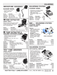
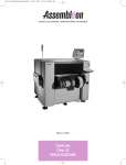
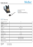
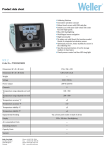
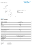
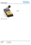
WHA 3000V Hot Air Station
Operating Instructions
Version 2.3
Page 1 of 15
COOPER TOOLS GmbH,
Carl-Benz-Str. 2 74354 Besigheim
Germany Tel: 07143-580-0, Fax: 07143-580-108
www.cooperhandtools.com/europe
Table of contents
1. Description
Technical data
5
6
2. Placing in operation
2.1 Manual operating mode
2.2 Automatic operating mode
2.3 Setting temperature profile
2.4 Starting program execution
2.5 Control of the vacuum function
2.6 Saving and loading temperature-time profiles
6
6
7
9
9
10
10
3. External sensor
3.1 External sensor with measuring function (MEASURE MODE)
3.2 Teach in Mode procedure
3.3 External sensor with control function (CONTROL MODE)
11
11
11
11
4. Lock Mode
12
5. Switching Temperature Conversion
12
6. Interface RS232
12
7. Operating guidelines
12
8. Fault messages
12
9. Accessories
13
10. Scope of supply
13
11. Hot Air Nozzles
14
12. Quick Reference
15
Page 2 of 15
COOPER TOOLS GmbH,
Carl-Benz-Str. 2 74354 Besigheim
Germany Tel: 07143-580-0, Fax: 07143-580-108
www.cooperhandtools.com/europe
Operating Instructions WHA3000V
Front view WHA3000V
1 LCD Display
2 "UP" Control key
3 "DOWN" Control key
4 Mains Switch
5 "TIME"/"PREHEAT" Control key (time specification auto. mode / preheating temperature)
6 "AIR" Control key (air volume)
7 "TEMP" Control key (hot air temperature)
8 LED Indicator, Vacuum
9 LED Indicator START / STOP
10 "START / STOP" Control key
11 "VAC" Control key (activate Vacuum)
12 "AUTO" – "MAN" Control key (changeover from Automatic – Manual operating mode)
13 LED Indicators AUTO-MAN operating mode
Page 3 of 15
COOPER TOOLS GmbH,
Carl-Benz-Str. 2 74354 Besigheim
Germany Tel: 07143-580-0, Fax: 07143-580-108
www.cooperhandtools.com/europe
Rear view WHA3000V
14
15
16
17
18
19
20
21
22
23
Connection WHP3000 (bottom heater) interface RS232 Interface
PC Interface, RS232
Connection for External Sensor Type K
Hand- piece Connecting Hose
Connection for Compressed air
Connection for Nitrogen N2 400- 600k Pa
Stand Switch Connection
Connection for Manual Control Console; Foot Switch
Mains Connection
Mains Fuse
Page 4 of 15
COOPER TOOLS GmbH,
Carl-Benz-Str. 2 74354 Besigheim
Germany Tel: 07143-580-0, Fax: 07143-580-108
www.cooperhandtools.com/europe
We thank you for the confidence you have shown by purchasing the Weller WHA3000V Hot Air
Station. During manufacturing, the strictest quality requirements are applied; these assure the
correct function of the device and make it possible to obtain optimal soldering results.
Warning!
Prior to placing the device in operation, please carefully read these operating instructions and the
safety instructions enclosed. If the safety instructions are not observed, there is a risk of injury.
The manufacturer accepts no liability for usage other than that described in the operating
instructions or for unauthorized modifications
The WELLER WHA3000V Hot Air Station complies with the EU declaration of conformity as per the
essential safety requirements in the directives 89/336/EEC and 73/23/EEC
1. Description
The Hot Air Station WHA3000V is suitable for difficult repairs on circuit boards with FINEPITCH
components. A well designed tool concept makes top process security possible with user-friendly
handling and technically advanced application solutions. And an extensive range of unit accessories
widens the possibilities for use of this repair station.
The hot air temperature at the hand-piece can be adjusted within the range of 50°C – 550°C (122°F
– 999°F). Through an external compressed air supply (or nitrogen N2 as an option), an adjustable
air flow rate in the range from 5 l/min – 50 l/min. The hot air temperature and air flow rate are
digitally controlled.
The vacuum necessary for lifting the component is integrated into the nozzle system and can be
activated to suit the operating mode chosen. Two operating modes are provided:
A
B
The "Manual“ operating mode (MAN) can be used for manual work at the hot air temperature
and air flow rate set. Hot air and vacuum can be activated using the foot switch, manual
remote control console or directly on the control Panel.
The "Automatic“ operating mode (AUTO) establishes a program with a 3-step time/
temperature profile, and can be used in conjunction with the WHP3000 Pre-Heat Plate
available as an accessory.
The parameters for hot air temperature, air flow rate, temperature of the optional WHP3000 PreHeat Plate and vacuum function can be adjusted separately and can be saved as a Rework Profile
for the specific application.
The repair station can also be complemented with the optional matched WBH3000S Circuit Board
Holder for X-Y alignment and a stand with Z-axis guide for the hot air hand-piece.
Page 5 of 15
COOPER TOOLS GmbH,
Carl-Benz-Str. 2 74354 Besigheim
Germany Tel: 07143-580-0, Fax: 07143-580-108
www.cooperhandtools.com/europe
Technical data
Dimensions (W x L x H)
Mains/line voltage
Power input
Air volume
Temperature range
Accuracy
Vacuum
Compressed air connection
Main fusing
Protection class
: 240 (9.44) X 270 (10.63) X 101 (3,97) mm (inches)
: 230 V (120 V) AC
: 475 W
: 5 – 50 l/min.
: 50°C – 550°C
: + - 30°C (+ - 54°F)
: 0.6 bar
: 400 - 600 kPa
: 230 V / T3,15 A (120 V / T6,3 A)
: 1 (control unit and handpiece hard grounded)
2. Placing in operation
Place the hand-piece with the hot air nozzle installed in the safety stand AKT 30. (Without the safety
stand or optional WBH30000S Circuit Board Holder the unit cannot be placed in operation.)
For operation of the WHA 3000V, clean, dry compressed air or, alternatively, nitrogen N2 is required.
The compressed air connections (18, 19) are on the rear side of the unit. For connection of the
compressed air supply, a compressed air hose with an outside diameter of 6 mm, which is suitable
for operating pressure, is required.
The nitrogen connection (19) serves to generate hot air.
The compressed air connection (18) serves to generate vacuum by means of a compressed air
converter.
If a separate nitrogen supply is not used, the compressed air connections (18) and (19) can be
linked to the Y-connector and supplied with normal compressed air.
Plug cable from safety stand or optional WBH3000S Circuit Board Holder (proximity switch), into
socket (20). Check whether the mains voltage matches the information on the rating plate. If the
mains voltage is correct, connect the controller to the mains. When the device is switched on, the
device name "WHA3000" and the software "Version" are displayed briefly. The electronics then
switch automatically to the default setting (Manual operating mode).
2.1 Manual operating mode
Information on
the display(1)
TEMP
AIR
PREHEAT
350 °C
25 l
OFF
Factory setting
Nozzle
Temp.
in °C
Air
Flow Rate
in l/min
Nozzle
Pre Heating
ON/OFF
In the Manual operating mode, the parameters for nozzle temperature, air flow rate and Switching
on or off the pre- heating can be set.
Page 6 of 15
COOPER TOOLS GmbH,
Carl-Benz-Str. 2 74354 Besigheim
Germany Tel: 07143-580-0, Fax: 07143-580-108
www.cooperhandtools.com/europe
Selection of parameters by pressing button:
•
TEMP
(7) : Nozzle temperature in °C/°F
(See Switching Temperature Conversation page 12)
•
AIR
(6) : Air flow rate in l/min
•
TIME/
PREHEAT (5) : Switch ON-OFF the nozzle preheating (standby) at 200°C (392°F)
with 5 l/min airflow.
After selection, the setting can be changed using the UP (2) or DOWN (3) Control Keys. Keeping the
Control Key depressed, rapidly changes the values.
The hot air and the nozzle vacuum can activated:
Directly on the Control Panel:
Hot air button START/STOP Control Key (10),
Vacuum VAC Control Key (11)
2-Position Foot Switch (21):
Hot air-Position 1, Vacuum- Position 2
(hot air and vacuum are only active in the Manual Mode, when
the Foot Switch is depressed)
Manual Control Console (21):
Hot air "AIR" Control Key, Vacuum "VAC" Control Key
When the hand-piece is placed in the AKT30 Safety Stand (20), the hot air is switched off by a Mirco
Switch. If the nozzle pre-heating is active (PREHEAT ON), the device switches to the standby mode
with reduced temperature and air flow rate (200°C/392°F-5l/min).
Note: Hot air is automatically disabled after 999 sec for safety reasons.
2.2 Automatic operating mode
The Automatic operating mode has a 3-step temperature-time profile.
The temperature-time profile can be expanded by connecting an optional WHP3000 bottom heater.
When the WHP3000 is connected via the RS232 interface (14) the bottom heater is integrated into
the time profile.
The temperature profile is comprised of the following 3-steps:
Pre-heat phase, system
Step 1
(ends with an audible tone)
Pre-heat phase, component Step 2
Reflow process (soldering) Step 3
The soldering process is normally started with the hot gas nozzle raised. At the end of step 1 there
is an audible tone, after this tone the nozzle should be placed over the component in the soldering
position. At the end of Step 3, raise or remove the nozzle from the application.
The following pre-settings must be made on the WHA3000V controller to define a customer-specific
temperature-time profile.
Page 7 of 15
COOPER TOOLS GmbH,
Carl-Benz-Str. 2 74354 Besigheim
Germany Tel: 07143-580-0, Fax: 07143-580-108
www.cooperhandtools.com/europe
Settings step 1 – step 3
Nozzle temperature
Temperature, bottom heat
Air flow rate
Time for the program step
50°C – 550°C (150°F / 999°F)
50°C – 400°C (150°F / 750°F) (optional with WHP3000)
5 l/min – 50 l/min
0 sec. – 999 sec.
The Automatic operating mode can be selected by pressing the AUTO/MAN Control Key.
The light emitting diodes (LED‘s) (13) indicate the related operating state.
Information on the display (1)
Nozzle
Pre-Heater
Nozzle
TEMP
210°C
300°C
210°C
AIR
40 l
25 l
30 l
TIME
100s
50s
15s
step 1
step 2
step 3
Nozzle or
bottom heater symbol
Temperature of the nozzle or
bottom heater (with WHP3000)
Air flow rate in l/min
Time remaining for the
temperature profile step in sec.
Page 8 of 15
COOPER TOOLS GmbH,
Carl-Benz-Str. 2 74354 Besigheim
Germany Tel: 07143-580-0, Fax: 07143-580-108
www.cooperhandtools.com/europe
2.3 Setting temperature profile
Select the parameters by pressing the Control Key:
•
TEMP (7):
Depressed Once
Depressed Twice
:
Nozzle temperature during the first step
Temperature of the bottom heater during the first
step
(only with WHP3000)
Repeat for Steps 1-3
Symbol for nozzle or bottom heater indicates which temperature is displayed.
•
AIR (6):
Depressed Once:
Air flow rate in l/min during the first step
Repeat for Steps 1-3
•
TIME/
PREHEAT (5) :
Depressed Once:
time remaining in the first step
Repeat for Steps 1-3
The active value is marked on the display and can be changed using the UP / DOWN (2) /
(3) Control Keys. Keeping the Control Key depressed, rapidly changes the value.
2.4 Starting program
The soldering process and thus the 3-step temperature-time profile is started:
Directly on the Control Panel:
START/STOP (10) Control Key, LED (9) illuminates.
2-Position Foot Switch (21):
START/STOP corresponds to setting 1 of the foot switch
(hot air and vacuum are only active when pressed)
Foot Switch Position 1-Air, Position 2-Vacuum
Manual Control Console (21):
(Optional)
START/STOP using the AIR Control Key
The nozzle temperature, air flow rate and the time remaining are indicated on the display (1). The
active program step is marked on the display.
When the hand-piece is placed in the safety stand, the program is interrupted and the hot air
switched off by an integrated contact. When the nozzle pre-heating is active (PREHEAT ON), the
device switches to the standby mode with reduced temperature and air flow rate.
Note: When using the WBH3000S Circuit Board Holder (20), the WHA3000V will automatically
turn “off” if the position of the Z-axis Head is moved from the “Locked” center position. It
must remain in position directly over the Hot Plate to allow for the WHA3000V to operate.
Page 9 of 15
COOPER TOOLS GmbH,
Carl-Benz-Str. 2 74354 Besigheim
Germany Tel: 07143-580-0, Fax: 07143-580-108
www.cooperhandtools.com/europe
2.5 Control of the vacuum function
The nozzle vacuum are activated:
Directly on the Control Panel:
VAC (11) Control Key, LED (8) illuminates.
2-Position Foot Switch (21):
vacuum corresponds to Position 2 of the foot switch
Manual Control Console (21):
(Optional)
using the VAC Control Key
If the VAC Control Key (11) is pressed prior to the start of a de-soldering process, the
vacuum integrated into the nozzle is activated automatically at the end of the process. The
vacuum function can also be enabled and disabled manually at any time during the
soldering process. If the vacuum is enabled during a soldering process, there is no
automatic activation at the end of the process.
Note: If the nozzle temperature is above 250°C/482°F the vacuum is automatically disabled
after 90 sec for safety reasons.
2.6 Saving and loading temperature-time profiles
A total of 10 temperature-time profiles can be saved. A default profile is saved in the 10 program
memories in the factory.
Press UP/DOWN Control Keys (2)/(3) simultaneously until the following menu appears on the
display (1)
PROGRAM 1
E X I
T
L O A D
S A V E
UP
PRESS AT
THE SAME
TIME
DOWN
The program memories 1 - 10 can be selected using the UP/DOWN Control Keys (2)/(3).
The preferred program can be selected by pressing the LOAD Control Key (6).
The indication on the display changes to the automatic mode and displays the selected parameters.
If a temperature-profile has been prepared, it can be saved in the selected program memory by
pressing the SAVE Control Key (5).
The menu can be exited without saving any changes using the EXIT Control Key (7).
Page 10 of 15
COOPER TOOLS GmbH,
Carl-Benz-Str. 2 74354 Besigheim
Germany Tel: 07143-580-0, Fax: 07143-580-108
www.cooperhandtools.com/europe
3. External Sensor
When using an external sensor (Thermocouple Type K), two different operating modes are
available. By pressing the Control Key "TIME" / "PREHEAT" (5) when switching on the unit (4), you
can toggle between the operating modes "MEASURE MODE" and "CONTROL MODE". The
following appears briefly in the display (1):
THERMOCOUPLE
MEASURE MODE
or
THERMOCOUPLE
CONTROL MODE
Both operating modes only become active once the external sensor (16) has been connected.
3.1 External Sensor with measuring function "MEASURE MODE" (factory setting)
In this operating mode, the external sensor only has a measuring function. The temperature of the
external sensor is shown in the display (1). The Hot Air Tool temperature control regulates the
setpoint value for the nozzle temperature.
External sensor active in "MEASURE MODE"
TEMP
250 °C
AIR
PREHEAT
25 l
OFF
3.2 Teach In Mode procedure
During the sequence of an automatic temperature-time profile, it is possible to continue switching
the process stages 1-3 manually by pressing the Control Key "TIME" / "PREHEAT" (5). If the
external sensor is suitably positioned on the assembly or component, its temperature can be
monitored during the entire process sequence and can be continued to be switched when the
desired specified temperatures (stage 1-3) have been reached. The times determined in this manner
are shown after the soldering or desoldering process in the display (1) and can be saved.
3.3 External sensor with control function "CONTROL MODE"
The temperature of the external sensor is controlled in this operating mode. The external sensor
records the actual value (control variable) for the temperature control. The setting for the setpoint
value at the unit must therefore be adapted to the measured temperature (actual value) of the
external sensor. The actual value of the external sensor is shown in the display (1).
External sensor active in "CONTROL MODE"
TEMP
250 °C
AIR
PREHEAT
25 l
OFF
A basic prerequisite for faultless application is direct contact of the sensor on the assembly or
component.
Page 11 of 15
COOPER TOOLS GmbH,
Carl-Benz-Str. 2 74354 Besigheim
Germany Tel: 07143-580-0, Fax: 07143-580-108
www.cooperhandtools.com/europe
4. Lock Mode
The device can be locked by inserting and removing a coded plug in socket (21). The current
soldering parameters cannot be further changed. The WHA3000P can only be operated using the
START/STOP (10) and VAC (11) Control Keys.
5. Switching Temperature Conversion
By pressing the Control Key "Temp" (7) when switching on the unit (4), you can toggle between the
operating modes "°C" and "°F". The following appears briefly in the display (1):
°C
or
°F
6. RS232 interface
Using additional software, the device can be operated completely via the RS232 interface (21).
7. Work instructions
The hot air nozzle is designed such that the vacuum plate lies flat on the component. The vacuum
plate is also used for the transfer of heat. When the vacuum is enabled, the component can be lifted
after the solder has reflowed. Here it is important to pre-heat the vacuum plate to operating
temperature prior to de-soldering. As an option, it is possible to use a vacuum cup in place of the
vacuum plate.
Nozzle change
Caution:
Risk of burns! The hot air nozzle remains hot for some time after power off or
removal.
The hot air nozzles are fastened to the heating element using a clamping screw. To change the
nozzle, loosen the screw and remove the hot gas nozzle using the Nozzle Change Tool provided.
Use of nitrogen
The use of nitrogen N2 reduces oxidation and the flux is active for a longer period. Nitrogen
is available in steel cylinders at regular trade outlets. The cylinder must be equipped with a
pressure reducer 0 – 10 bar.
Caution!: Ensure adequate room ventilation when using nitrogen.
Page 12 of 15
COOPER TOOLS GmbH,
Carl-Benz-Str. 2 74354 Besigheim
Germany Tel: 07143-580-0, Fax: 07143-580-108
www.cooperhandtools.com/europe
8. Error messages
Error
Description
Rectification
ERROR 75
ERROR 76
Offset entry on heating element change incorrect
Heating element faulty
Repeat process
Replace heating element
ERROR 110
WHP3000 housing temperature exceeded
Allow to cool down
REMOTE
LOCKED
TOOL STAND
Input inhibited (can only be operated using PC)
WHA locked (lock function)
AKT30 Stand (or WBH3000 Proximity Sensor)
not connected
Operate using PC
Unlock WHA
Connect to socket (20)
9. Accessories
0053119099
0058754951
0058757770
0058736780
0051504899
WBH3000
WBH3000S
WHP3000
External sensor type K ∅ 0.5mm
External sensor type K ∅ 0.25mm
Foot switch
Manual Control Console
Stand for six hot air nozzles
Circuit board holder
Circuit board holder with hot air tool stand
Bottom heating plate
10. Items supplied
WHA3000V Controller with hand-piece
AKT30 Safety stand
0051504999 Nozzle exchange tool
Coded plug
Tool kit (2,5 mm hex wrench w/2 3 mm x 6 mm L screws provided)
0058750721 Hot air nozzle NQ30
Main power cord 120VAC
0058757770 Foot switch (only USA Version)
Product CD-Rom (Operating instructions incl. WHA control software)
Subject to technical change without notice!
Page 13 of 15
COOPER TOOLS GmbH,
Carl-Benz-Str. 2 74354 Besigheim
Germany Tel: 07143-580-0, Fax: 07143-580-108
www.cooperhandtools.com/europe
11. Hot Air Nozzles
Hot Air Nozzles for HAP 3
Round Nozzles
Hot air nozzles 2-sides heated (Type ND)
Hot air nozzles 4-sides heated (Type NQ))
Measuring nozzle 005 87 368 75
005 87 368 39 NQT Hot air nozzle 22,0 x 22,0 mm
005 87 368 41 NQT10 Hot air nozzle 14,8 x 14,8 mm
005 87 368 42 NQT25 Hot air nozzle 18,0 x 18,0 mm
005 87 368 43 NQT Hot air nozzle 16,0 x 16,0 mm
Page 14 of 15
COOPER TOOLS GmbH,
Carl-Benz-Str. 2 74354 Besigheim
Germany Tel: 07143-580-0, Fax: 07143-580-108
www.cooperhandtools.com/europe
12. Quick Reference WHA3000P/V
•
Changeover
auto-manual operating mode
•
UP Control Key increase value
•
DOWN Control Key decrease value
•
Activating vacuum function
•
Start/Stop soldering process
Respectively hot air function
•
Setting hot air temperature
(manual mode)
•
Setting hot air temperature and
bottom heater for step 1 – 3
(auto mode)
•
Setting flow rate
(manual mode)
•
setting flow rate for step 1 – 3
(auto mode)
•
Time setting for step 1 – 3
(auto mode)
•
Nozzle preheating ON/Off
(manual mode)
•
Save and load program
for temperature profiling
Auto
Man
Vac
Start/Stop
Temp
Air
Time
/
Preheat
+
•
Switching Temperature Conversion
(Pressing when switching on the WHA3000P)
Page 15 of 15
Program
Temp
COOPER TOOLS GmbH,
Carl-Benz-Str. 2 74354 Besigheim
Germany Tel: 07143-580-0, Fax: 07143-580-108
www.cooperhandtools.com/europe