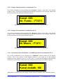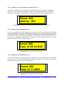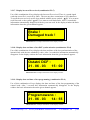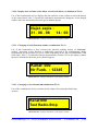
1
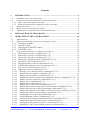
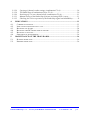
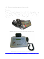
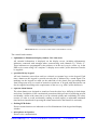
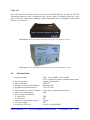
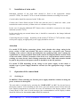
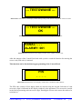
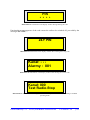
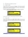
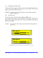
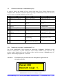
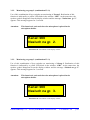
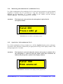
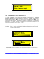
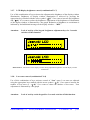
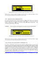
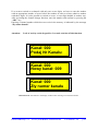
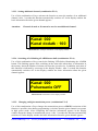
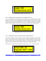
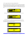
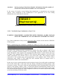
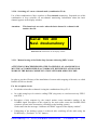
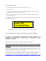
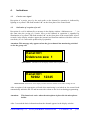
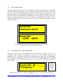
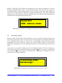
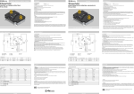
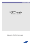
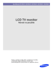
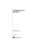
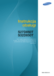
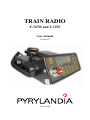
TRAIN RADIO
F-747M and F-747S
User manual
Version 4.0
Warsaw 2006
Contents
1.
INTRODUCTION.......................................................................................................... 4
1.1.
INTENDED USE OF THE TRAIN RADIO .............................................................................. 4
1.2.
CONSTRUCTION AND COMPONENTS OF THE TRAIN RADIO............................................... 4
1.2.1. Basic components of the train radio.......................................................................... 4
1.2.2. Short description of the components of the train radio ............................................. 6
1.3.
TECHNICAL DATA .......................................................................................................... 8
1.4.
BASIC FUNCTIONS OF THE TRAIN RADIO ......................................................................... 9
1.5.
ADDITIONAL ACCESSORIES AND COMPATIBLE DEVICES.................................................. 9
2.
INSTALLATION OF TRAIN RADIO ...................................................................... 10
3.
OPERATION OF THE CONTROL HEAD.............................................................. 10
3.1.
SWITCHING ON ............................................................................................................. 10
3.2.
BASIC FUNCTIONS SELECTED WITH ONE PRESS OF A KEY .............................................. 13
3.2.1. Sending an ALARM ................................................................................................. 13
3.2.2. Sending CALLS........................................................................................................ 13
3.2.3. Changing the CHANNEL number ........................................................................... 14
3.2.4. VOLUME control .................................................................................................... 14
3.3.
FUNCTIONS REALISED BY A COMBINATION OF KEYS ..................................................... 15
3.3.1. Monitoring on group 1 (combination F1+1)........................................................... 15
3.3.2. Monitoring on group 2 (combination F1+2)........................................................... 16
3.3.3. Monitoring on group 3 (combination F1+3)........................................................... 16
3.3.4. Monitoring with unblocked AF (combination F1+4) .............................................. 17
3.3.5. Squelch On / Off (combination F1+5)..................................................................... 17
3.3.6. Keypad brightness control (combination F1+6) ..................................................... 18
3.3.7. LCD Display brightness control (combination F1+7) ............................................ 19
3.3.8. Low tones control (combination F1+8) .................................................................. 19
3.3.9. High tones control (combination F1+9) ................................................................. 20
3.3.10. Entering a new channel number (combination F1+0)......................................... 20
3.3.11. Display Function number (combination F2+1) ................................................... 22
3.3.12. Display Internal number (combination F2+2)..................................................... 22
3.3.13. Information about the number of an additional channel (combination F2+3) ... 22
3.3.14. Number of activated alarms (combination F2+4) ............................................... 23
3.3.15. Display time (combination F2+5)........................................................................ 23
3.3.16. Display date (combination F2+6)........................................................................ 23
3.3.17. Display last text file received (combination F2+7) ............................................. 24
3.3.18. Display date and time of last DCF synchronisation (combination F2+8) .......... 24
3.3.19. Display date and time of last programming (combination F2+9) ....................... 24
3.3.20. Display date and time of the oldest record in the history (combination F2+0)... 25
3.3.21. Changing of radio Function number (combination F3+1).................................. 25
3.3.22. Changing on test channel 000(combination F3+2) ............................................. 25
3.3.23. Setting additional channel (combination F3+3).................................................. 26
3.3.24. Switching off of blinking ALARM button bulb (combination F3+4).................... 26
3.3.25. Changing on high transmission power (combination F3+5)............................... 26
3.3.26. Changing on low transmission power (combination F3+6) ................................ 27
3.3.27. Signalling of DCF time standard reception (combination F3+7) ...................... 27
PYRYLANDIA Sp. z o. o. Two way Train Radio F-747M and F-747S
User manual v. 4.0
p. 2
3.3.28.
3.3.29.
3.3.30.
3.3.31.
3.3.32.
4.
4.1.
4.2.
4.3.
4.4.
4.5.
4.6.
5.
5.1.
5.2.
Copying of channels radio settings (combination F3+8) .................................... 28
Test Radio-Stop (Combination of keys F3+9)...................................................... 29
Switching off / on two-channel mode (combination F3+0).................................. 31
Manual testing of the Radio-Stop Systems with using PKPs’ testers................... 31
Checking the correct operation of the Radio Stop signal and ALARM key ......... 32
INDICATIONS............................................................................................................. 33
CARRIER WAVE SIGNAL................................................................................................ 33
INDICATION OF RECEPTION OF A CALL.......................................................................... 33
RECEIVING AN ALARM ................................................................................................. 34
RECEIVING THE DCF RADIO TIME STANDARD .............................................................. 34
RECEIVING A TEXT FILE ............................................................................................... 35
SWITCHING ON TRANSMISSION ..................................................................................... 36
MAINTENANCE OF THE TRAIN RADIO ............................................................. 36
RUNNING INSPECTION .................................................................................................. 36
PERIODIC INSPECTION .................................................................................................. 36
PYRYLANDIA Sp. z o. o. Two way Train Radio F-747M and F-747S
User manual v. 4.0
p. 3
1.
Introduction
1.1.
Intended use of the train radio
Two way train radio F-747M and F-747S are intended for use in railways dispatch
communication networks amongst others, railways, and ensure radio communication between
landline radios (e.g. traffic controllers), mobile radios (e.g. railway engines) and portable
radios.
These train radios can also be used to work with other systems (see additional accessories,
compatible devices 1.5).
1.2.
Construction and components of the train radio
The train radio is designed using the latest technology. Surface mounting, specialised
processors, and frequency synthesis are used. The device consists of a control head and a
Tx/Rx unit together with a power supply (model F-747S) or control head, Tx/Rx unit and a
power supply (model F-747M).
1.2.1.
Basic components of the train radio
The train radio set consists of:
• control head F-747M or F-747S
• Tx/Rx unit with power supply (landline version)
• Tx/Rx unit (mobile version)
• power supply Mascot or Alfatronix (mobile version)
• connecting cable
• speaker (landline version)
• microphone
PYRYLANDIA Sp. z o. o. Two way Train Radio F-747M and F-747S
User manual v. 4.0
p. 4
Illustration 1. The complete train radio set F-747M, without standard rack (mobile version)
Illustration 2. The complete train radio set F-747S (landline version)
PYRYLANDIA Sp. z o. o. Two way Train Radio F-747M and F-747S
User manual v. 4.0
p. 5
1.2.2.
Short description of the components of the train radio
Control head
The purpose of the control head is to control the train radio. It is housed in an aesthetic casing
made from plastic ABS (model F-747S) or in the mobile version (model F-747M) from cast
aluminium with the possibility of using the keyboard in two plains. Thanks to the plastic
casing it is possible to install an additional magnetic card reader or electronic card reader,
enabling the identification and authorisation for people using the control head. During the
design stage, care was taken to make both control heads ergonomic.
Illustration 3.View of the front plate of the control head F-747M (mobile version)
Illustration 4. Front view of the control head F-747S (landline version)
PYRYLANDIA Sp. z o. o. Two way Train Radio F-747M and F-747S
User manual v. 4.0
p. 6
Illustration 5. Rear view of the control head F-747S (landline version)
The control head contains:
• alphanumeric illuminated display window 2x16 characters
All essential information is displayed on the display screen, including alphanumeric
indicators connected with amongst others, manoeuvring work channels e.g. “Kielce 2”.
These indicators are programmed by the producer or in the user’s service centre e.g. in the
PKP service centre using a PC computer. A display screen with Cyrillic characters can also
be supplied.
• specialist 20-key keypad
All basic functions (most often used) are selected on separate keys on the keypad. Each
time a button on the keypad is pressed correctly this is indicated by a sound signal. The
markings on the keypad are made on the underside of the plastic, thus preventing them
from being worn away as a result of normal wear and tear. A keypad with descriptions can
also be supplied according to the requirements of the user (e.g. with Cyrillic characters).
• separate alarm button
The alarm button was designed to stand out from the other keys, differing in both shape
and colour. In addition, it has a mechanical protection which prevents it from being pressed
accidentally, whilst at the same time it can be selected quickly and confidently (for safety
reasons, in order to avoid accidentally sending an alarm signal, an adjustable minimum
time has been introduced for pressing the alarm button before the function is activated).
• flashing LED diodes
Ensure certain functions are indicated as well as illumination of the keypad and display
window.
• microphone and speaker
Ensure voice communication.
PYRYLANDIA Sp. z o. o. Two way Train Radio F-747M and F-747S
User manual v. 4.0
p. 7
Tx/Rx unit
The Tx/Rx unit was constructed based on the radio MAXON PM100. In model F-747S the
Transmission-Receiver unit is integrated with a power supply. In addition, radio has a few
types of selective calling, the possibility of data transmission and is compatible with external
devices e.g. GPS units.
Illustration 6. View of the Tx/Rx unit with power supply F-747M (mobile version)
Illustration 7. View of the Tx/Rx unit with power supply F-747S (landline version)
1.3.
Technical Data
• frequency range:
•
•
•
•
•
•
•
type of operation:
type of broadcast:
number of conversation channels:
neighbouring channel interval:
interval between extreme channels:
max power consumption:
power rating of transmitter
• high power:
• low power:
• tolerance of operating frequency:
• AF power output:
• sensitivity of receiver:
VHF : 136-162 MHz, 148-174 MHz
(150-156 MHz for railway communication needs)
simpleks, duosimpleks
16K0F3E
maximum 400
12,5 or 25 kHz
as the range of operating frequencies
80W
25W
5W
±4 ppm
5W
0,25µV at 12dB SINAD
PYRYLANDIA Sp. z o. o. Two way Train Radio F-747M and F-747S
User manual v. 4.0
p. 8
1.4.
Basic functions of the train radio
Among the functions provided by the train radio are the following:
•
•
•
•
•
•
•
•
•
•
•
•
•
•
•
•
•
works on any programmed radio channel;
transmits and receives an emergency signal;
transmits and receives test signals of the radio-stop system;
monitoring with unblocked AF of the receiver (speaker switched on);
monitoring with blocked AF of the receiver (speaker switched off);
transmits information preceded by group call 1, 2 or 3;
transmits and receives locomotive identification signals (functional and internal no.);
the radio can be programmed using an external PC computer separately for each channel:
its number, name (up to 16 characters), frequency of the transmitter, frequency of the
receiver, power of the transmitter (large or small), latitude of the channel, switching on the
continuous tone-coded squelch system CTCSS, choice of group to be monitored, activation
of the function enabling identification numbers for the radio to be sent (functional and
internal number);
full archives of events in the system’s memory (approx. 10000 recent events);
test of the train radio’s internal systems;
monitoring of two channels (omitting channels with numbers from 0 to 20 )
information for Users on a 2x16 character, (alphanumeric), illuminated LCD display
window;
16 - step volume regulation;
16 - step low and high tones regulation;
16 - step illumination of keypad and display window regulation;
sound signal indicating correct use of the keypad;
possibility to switch on sound signal for synchronisation of internal clock with the
transmitted time standard;
sound signal of the moment of beginning a conversation;
digital transmission of any information (text file to subscriber);
digital transmission (any file);
digital transmission of time standard (concerns landline version).
•
•
•
•
•
For Users’ convenience in addition we propose the following:
• emergency power supply (for model F-747S );
• additional alarm siren (for model F-747S );
• additional PTT key in the form of a foot button (model F-747S).
1.5.
Additional accessories and compatible devices
The following external devices designed by Pyrylandia may be connected to the train radio:
• DCF time standard Receiver Module for model F-747S;
• Radio Calls Recorder
• Emergency Power Supply System for model F-747S
PYRYLANDIA Sp. z o. o. Two way Train Radio F-747M and F-747S
User manual v. 4.0
p. 9
2.
Installation of train radio
Individual elements of the train radio should be fixed to the appropriate clamps
(model F-747M). For model F-747S we set the individual elements according to our needs.
Coaxial cables should be connected to the Tx/Rx unit.
Connect the Control Head and the Tx/Rx unit with the aid of a multi-core cable, (such
transmission ensures accuracy of data sent over a distance of up to 20m).
In the case of using the additional PTT button (foot), it should be connected to the clamps
indicated (model F-747S).
In the case of using an external alarm siren, it should be connected to the clamps indicated
(model F-747S).
Connecting the power supply - depending on the model (F-747M or F-747S) and the voltage
of the power supply, an appropriate power supply should be selected.
Attention
For model F-747S before connecting, please check whether the voltage rating in the
power socket is 230V and whether the power socket has a protective pin. Neutral
earthing of the socket is allowed providing that an equalizing cable exists, causing the
equalization of voltage potentials between the neutral earthing installation and the earth
of the train radio’s aerial. Connection of the device to a socket without earth or neutral
earthing can cause electric shock. During connection of the Tx/Rx unit attention should
be paid to the position of the power switch (it should be in the Off position).
For model F-747M depending on the voltage of the power supply in the vehicle, a
suitable type of power supply should be selected (for the appropriate range of input
voltage).
3.
Operation of the control head
3.1.
Switching on
WARNING! When switching on, first the power supply should be switched on using the
power switch on its front plate.
The train radio is switched on by pressing the “ZASILANIE” or “0/1” key located next to
the display window. After switching on, the device goes into autotest mode. In this mode the
basic internal components are checked. All errors are indicated on the display window of the
Control Head. In the event of such messages, the recommendations on the display window
should be followed or the service centre should be contacted.
PYRYLANDIA Sp. z o. o. Two way Train Radio F-747M and F-747S
User manual v. 4.0
p. 10
--- TESTOWANIE --Illustration 8. Information in the display window during testing of the internal components of the train radio.
--- TESTOWANIE --OK
Illustration 9. Information in the display window after completion of the test.
KANAL: - - ALARMY: 001
Illustration 10. Information in the display window on the number of alarms sent.
After the autotest of the Control Head ends with a positive result the function for entering the
access code (PIN code) is initiated.
This function can be blocked during programming of the Control Head.
PIN
_ _ _ _
Illustration 11. Information in the display window after command “Podaj kod PIN”
The PIN code consists of four digits which are entered using the keypad. Selection of each
successive digit is indicated on the display window by the appearance of a successive asterisk
in the field representing each successive digit. Entering the correct code causes the radio to be
switched on.
PYRYLANDIA Sp. z o. o. Two way Train Radio F-747M and F-747S
User manual v. 4.0
p. 11
PIN
* * * *
Illustration 12. Information in the display window during entering the code.
Entering the wrong sequence of the code causes the radio to be switched off, preceded by the
message “ZŁY PIN”.
ZŁY PIN
Illustration 13. Information in the display window after entering the wrong code
Kanał: - - Alarmy : 001
Illustration 14. Information in the display window after entering the correct code.
Kanał: 000
Test Radio-Stop
Illustration 15. Information in the display window after completion of the tests and switching to standard
operating mode.
PYRYLANDIA Sp. z o. o. Two way Train Radio F-747M and F-747S
User manual v. 4.0
p. 12
3.2.
Basic functions selected with one press of a key
3.2.1.
Sending an ALARM
Sending an alarm is done by pressing the key ALARM – in order to prevent accidental
sending of the alarm a time delay has been pre-programmed, after which the function is
preformed. The time is regulated in the range from 0 to 10s. The alarm is sent on the channel
which was selected earlier as the working channel.
WARNING: SENDING THE ALARM MUST BE IN ACCORDANCE WITH THE
LEGALLY BINDING REGULATIONS
Kanał: 000
Wysyłanie ALARMU
Illustration 16. Information in the display window during sending an alarm
Sending an alarm is indicated by flashing LED diodes illuminating the ALARM key.
3.2.2.
Sending CALLS
Calls are sent by pressing the keys marked ZEW 1, ZEW 2 and ZEW 3. Calls are sent on the
channels which we earlier selected as working. In order to prevent an alarm sequence being
achieved with the help of calls, a minimum time between successive pressings of keys has
been introduced.
Kanał: 000
Nadanie zewu
1
Illustration 17. Information in the display window when the key ZEW 1 is pressed.
Kanał: 000
Nadano zew
1
Illustration 18 Information in the display window after releasing the ZEW1 key.
PYRYLANDIA Sp. z o. o. Two way Train Radio F-747M and F-747S
User manual v. 4.0
p. 13
3.2.3.
Changing the CHANNEL number
To change the channel press the key marked with the arrow symbol ” “ and “ ” (button no.
7 and 9). The key marked “ (9)” increases the number of the channel by 1. The key marked
“ (7)” reduces the number of the channel by 1.
WARNING! Using this method to change channels we cannot switch to the channel
marked as channel “0”
3.2.4.
VOLUME control
The volume control is realised by pressing the up or down arrow key.
The key marked “ ” increases the volume. Regulation of the volume is displayed in the
display window. The key marked “ ” reduces the volume. Regulation of the volume is
displayed in the display window. Reduction of the volume to the minimum is displayed by an
additional indicator MIN.
Attention:
The construction of the radio prevents the volume from being reduced to
the level “0”.
Siła głosu
Siła głosu
M I N
Illustration 19. Information in the display window during regulation of the volume.
PYRYLANDIA Sp. z o. o. Two way Train Radio F-747M and F-747S
User manual v. 4.0
p. 14
3.3.
Functions realised by a combination of keys
In order to reduce the number of keys on the front plate of the Control Head we have
multiplied their functions. Functions realised by using a combination of keys are used very
rarely or once e.g. during installation of the device.
1
2
F1
Monitoring of GROUP 1
Monitoring of GROUP 2
3
Monitoring of GROUP 3
4
8
Monitoring with unblocked
speaker
Squelch on / off
Brightness of keypad
Brightness of display
window
Low tones
9
High tones
0
Enter new channel no.
5
6
7
3.3.1.
F2
Display Function no.
Display Internal no.
F3
Change Function no.
Change channel to 000 Test
Radio-Stop
Display no. of additional
Change / set additional
channel
channel
Display number of alarms
Switch off flashing light of
ALARM button
Display time
Change power to high
Display date
Change power to low
Display last received text
Switch on indicator of
file
reception DCF / Time
Display date and time of last Cloning of channels ...
synchronisation
Display date and time of last Test of Radio-Stop System/
programming
Transmission of time
standard
Display date and time of
Two-channel mode On / Off
oldest record in the history
Monitoring on group 1 (combination F1+1)
Use of this combination of keys switches on monitoring of Group 1. Realisation of this
function is indicated by a yellow LED diode in the window “GR1”. At the same time, the
speaker symbol disappears from the display window and the message “Nasłuch na gr. 1”
appears. This message appears for 3 seconds.
Attention:
This function is activated when the microphone is placed in the
microphone holder.
Kanał: 000
Nasłuch na gr. 1.
Illustration 20. Information in the display window
PYRYLANDIA Sp. z o. o. Two way Train Radio F-747M and F-747S
User manual v. 4.0
p. 15
3.3.2.
Monitoring on group 2 (combination F1+2)
Use of this combination of keys switches on monitoring of Group 2. Realisation of this
function is indicated by a yellow LED diode in the window “GR2”. At the same time, the
speaker symbol disappears from the display window and the message “Nasłuch na gr. 2”
appears. This message appears for 3 seconds.
Attention:
This function is activated when the microphone is placed in the
microphone holder.
Kanał: 000
Nasłuch na gr. 2.
Illustration 21. Information in the display window.
3.3.3.
Monitoring on group 3 (combination F1+3)
Use of this combination of keys switches on monitoring of Group 3. Realisation of this
function is indicated by a yellow LED diode in the window “GR3”. At the same time, the
speaker symbol disappears from the display window and the message “Nasłuch na gr. 3”
appears. This message appears for 3 seconds.
Attention:
This function is activated when the microphone is placed in the
microphone holder.
Kanał: 000
Nasłuch na gr. 3.
Illustration 22. Information in the display window.
PYRYLANDIA Sp. z o. o. Two way Train Radio F-747M and F-747S
User manual v. 4.0
p. 16
3.3.4.
Monitoring with unblocked AF (combination F1+4)
Use of this combination of keys unblocks of AF (we hear all conversations on a given channel
regardless of whether they are preceded by a ring tone). Realisation of this function is
indicated by the appearance of a speaker symbol in the window and the message
“Praca z odbl. gł.”. This message appears for 3 seconds.
Attention:
This function is activated when the microphone is placed in the
microphone holder.
Kanał: 000
Praca z odbl. gł
Illustration 23. Information in the display window.
3.3.5.
Squelch On / Off (combination F1+5)
Use of this combination of keys switches on or off the Squelch function (noise reduction).
Activation of this function is indicated by an appropriate message in the display window. This
message appears for 3 seconds.
Attention:
This function is activated when the selective call system is switched off or
the microphone is removed from the holder (both these functions are
indicated by the speaker symbol in the display window).
Kanał : 000
Blok. szumu wł.
Illustration 24. Information in the display window (Squelch On).
PYRYLANDIA Sp. z o. o. Two way Train Radio F-747M and F-747S
User manual v. 4.0
p. 17
Kanał : 000
Blok. Szumu wył.
Illustration 25. Information in the display window (Squelch Off)
3.3.6.
Keypad brightness control (combination F1+6)
Use of this combination of keys activates the adjustment of the brightness of the keypad
illumination. Brightness of keypad illumination is achieved by using the appropriate keys
marked with arrow symbol “ (5)” if we want to increase the brightness, and “ (0)” if we
want to reduce the brightness. Adjustment the brightness of illumination of the keypad is
illustrated by a bar graph. Reduction of brightness to a minimum is indicated by and
additional message on the display window – “MIN”.
Attention:
Lack of activity on the keypad brightness adjustment keys for 3 seconds
switches off this function.
Illustration 26. Information in the display window during adjustment brightness of keypad illumination
PYRYLANDIA Sp. z o. o. Two way Train Radio F-747M and F-747S
User manual v. 4.0
p. 18
3.3.7.
LCD Display brightness control (combination F1+7)
Use of this combination of keys activates the adjustment the brightness of the display window
illumination. Brightness of display window illumination is achieved by pressing the
appropriate keys marked with the arrow symbol “ (5)” if we want to increase the brightness
and “ (0)” if we want to reduce the brightness. Adjustment of the brightness of illumination
of the display window is illustrated by a bar graph. Reduction of brightness to a minimum is
indicated by and additional message on the display window – “MIN”.
Attention:
Lack of activity of the keypad brightness adjustment keys for 3 seconds
switches off this function.
Illustration 27. Information in the display window during adjustment brightness of LCD display window
illumination
3.3.8.
Low tones control (combination F1+8)
Use of this combination of keys activates control of “Low” tones. Low tones are adjusted
using the appropriate keys marked with the arrow symbol “ (5)” if we want to increase the
number of low tones or “
(0)” if we want to reduce the number of low tones. Tone
adjustment is illustrated by a bar graph.
Attention:
Lack of activity on the keypad for 3 seconds switches off this function.
PYRYLANDIA Sp. z o. o. Two way Train Radio F-747M and F-747S
User manual v. 4.0
p. 19
Illustration 28. Information in the display window during adjustment of low tones.
When the line on the bar graph is pointing towards the left, we reduce the number of low
tones, and when pointing towards the right we increase them.
3.3.9.
High tones control (combination F1+9)
Use of this combination of keys activates regulation of “High” tones. High tones are adjusted
using the appropriate keys marked with the arrow symbol “ (5)” if we want to increase the
number of high tones or “ (0)” if we want to reduce the number of high tones. Tone
adjustment is illustrated by a bar graph.
Attention:
Lack of activity on the keypad for 3 seconds switches off this function.
Illustration 29. Information in the display window during adjustment of high tones.
.
When the line on the bar graph is pointing towards the left, we reduce the number of high
tones, and when pointing towards the right we increase them.
3.3.10. Entering a new channel number (combination F1+0)
Use of this combination of keys activates the function enabling the quick selection of any
channel (since the train radio’s memory can hold a maximum of 400 channels, channel
selection using keys to change the channel up or down by 1 would take a long time). After
activating this function the following message appears on the display window: “Podaj Nr
Kanału :”. Next, with the help of the numerical keypad we enter the number of the channel
that we want to select. When the numerical keypad is used, the following message appears in
the display window: “Nowy kanał :” and space for entering the three-digit number. Entering
a three-digit number completes the change of channel.
PYRYLANDIA Sp. z o. o. Two way Train Radio F-747M and F-747S
User manual v. 4.0
p. 20
If we want to switch on a channel with only one or two digits, we have to enter the number
with an appropriate number of zeros before the number in order to always obtain a number
with three digits. It is also possible to switch on a one- or two-digit channel in another way.
After activating the channel change function, enter the number and confirm by pressing the
“AKC” key.
Entering a channel number which does not exist in the memory is indicated by the message
“Zły numer kanału”.
Attention:
Lack of activity on the keypad for 3 seconds switches off this function.
Kanał: 000
Podaj Nr Kanału:
Kanał: 000
Nowy kanał: 009
Kanał: 000
Zły numer kanału
Illustration 30. Information in the display window when entering a new channel number.
PYRYLANDIA Sp. z o. o. Two way Train Radio F-747M and F-747S
User manual v. 4.0
p. 21
3.3.11. Display Function number (combination F2+1)
Use of this combination of keys displays the “Function” number of the radio in the display
window. After 3 seconds this information automatically disappears. In the display window the
basic information about the given channel appears.
Kanał: 000
Nr. Funkc. : F747!!
Illustration 31. Information in the display window about the function number
3.3.12. Display Internal number (combination F2+2)
Use of this combination of keys displays the “Internal” number of the radio in the display
window. After 3 seconds this information automatically disappears. In the display window the
basic information about the given channel appears.
Kanał: 000
Nr Wewn. : F747!!
Illustration 32. Information in the display window about the internal number.
3.3.13. Information about the number of an additional channel (combination F2+3)
Use of this combination of keys displays the “Additional” channel number in the display
window. This is the number of the channel which we can switch on in dual channel
monitoring mode (numbers from 21 to 399). After 3 seconds this information automatically
disappears. In the display window the basic information about the given channel appears.
Kanał: 000
Kanał dodatk: 100
Illustration 33. Information in the display window about the number of the additional channel.
PYRYLANDIA Sp. z o. o. Two way Train Radio F-747M and F-747S
User manual v. 4.0
p. 22
3.3.14. Number of activated alarms (combination F2+4)
Use of this combination of keys displays in the display window the number of “Alarms”
which were sent from the train radio given. After 3 seconds this information automatically
disappears. In the display window the basic information about the given channel appears.
Kanał: 000
Alarmy : 001
Illustration 34. Information in the display window about the number of alarms sent.
3.3.15. Display time (combination F2+5)
Use of this combination of keys displays the current time of the internal clock in the display
window. In addition we receive information on whether this is synchronised time with the
time standard (time is considered to be synchronised time when the last synchronisation was
no more than 72 hours ago). Synchronised time is indicated by the message “DCF”. After 3
seconds this information automatically disappears. In the display window the basic
information about the given channel appears.
Kanał: 000
Czas 12:50:33 DCF
Illustration 35. Information in the display window.
3.3.16. Display date (combination F2+6)
Use of this combination of keys displays the current date of the internal clock in the display
window. After 3 seconds this information automatically disappears. In the display window the
basic information about the given channel appears.
Kanał: 000
Data 12.11.2003
Illustration 36. Information in the display window.
PYRYLANDIA Sp. z o. o. Two way Train Radio F-747M and F-747S
User manual v. 4.0
p. 23
3.3.17. Display last text file received (combination F2+7)
Use of this combination of keys displays the last text file received. There is a sound signal
each time a text file is received by radio. The text may have a maximum of 256 characters.
To scroll the text received, use the keys marked with the arrow symbol “ (5)” if we want to
scroll forward, or the symbol “ (0)” if we want to scroll backwards. After 3 seconds this
information automatically disappears if the keys are not used. In the display window the basic
information about the given channel appears.
Brake !
Damaged track !
Illustration 37. Example information in the display window.
3.3.18. Display date and time of last DCF synchronisation (combination F2+8)
Use of this combination of keys displays the date and time of the last synchronisation of the
internal clock with the time standard by radio. After 3 seconds this information automatically
disappears. In the display window the basic information about the given channel appears.
Ostatni DCF :
31 . 06 . 03
15 : 00
Illustration 38. Example information in the display window.
3.3.19. Display date and time of last programming (combination F2+9)
Use of this combination of keys displays the date and time of the last programming of the
control head. After 3 seconds this information automatically disappears. In the display
window the basic information about the given channel appears.
Programowano :
31 . 06 . 03
14 : 55
Illustration 39. Example information in the display window
PYRYLANDIA Sp. z o. o. Two way Train Radio F-747M and F-747S
User manual v. 4.0
p. 24
3.3.20. Display date and time of the oldest record in the history (combination F2+0)
Use of this combination of keys displays the date and time of the earliest record in the history
of the control head. After 3 seconds this information automatically disappears. In the display
window the basic information about the given channel appears.
Najst. zapis :
31 . 06 . 98
14 : 00
Illustration 40. Example information in the display window
3.3.21. Changing of radio Function number (combination F3+1)
Use of this combination of keys activates the function enabling change of “Function”
number. Activation of this function is additionally restricted in the programming (during
programming by the producer or service centre depending on the place of installation of the
train radio). After 3 seconds this function automatically switches off. In the display window
the basic information about the given channel appears.
Kanał: 000
Nr Funk. : 12345
Illustration 41. Example information in the display window
3.3.22. Changing on test channel 000(combination F3+2)
Use of this combination of keys switches on the channel for testing the Radio-Stop
systems.
Kanał:000
Test Radio-Stop
Illustration 42. Example information in the display window
PYRYLANDIA Sp. z o. o. Two way Train Radio F-747M and F-747S
User manual v. 4.0
p. 25
3.3.23. Setting additional channel (combination F3+3)
Use of this combination of keys activates the function to enter the number of an additional
channel. After 3 seconds this function automatically switches off. In the display window the
basic information about the given channel appears.
Attention:
Channels from 0 to 20 cannot be used as an additional channel.
Kanał: 000
Kanał dodatk : 100
Illustration 43. Example information in the display window
3.3.24. Switching off of blinking ALARM button bulb (combination F3+4)
Use of this combination of keys cancels the flashing LED diodes illuminating the ALARM
button. This flashing appears after switching on the train radio when there is information in
the memory about the number of alarms sent from the given device. In addition, activation of
this function is indicated by a message in the display window. After 3 seconds this function
automatically switches off. In the display window the basic information about the given
channel appears.
Kanał: 000
Pulsowanie OFF
Illustration 44. Information in the display window.
3.3.25. Changing on high transmission power (combination F3+5)
Use of this combination of keys changes the transmission power to HIGH. Activation of this
function is possible when during programming we declare that the given channel can operate
in high power mode. After completing this function information appears in the display
window about the change in transmission power. After 3 seconds this function automatically
switches off. In the display window the basic information about the given channel appears.
PYRYLANDIA Sp. z o. o. Two way Train Radio F-747M and F-747S
User manual v. 4.0
p. 26
Kanał: 000
Zmiana mocy na H
Illustration 45. Information in the display window.
3.3.26. Changing on low transmission power (combination F3+6)
Use of this combination of keys changes the transmission power to LOW. Activation of this
function is possible when during programming we declare that the given channel can operate
in high power mode. After completing this function information appears in the display
window about the change in transmission power. After 3 seconds this function automatically
switches off. In the display window the basic information about the given channel appears.
Kanał: 000
Zmiana mocy na L
Illustration 46. Information in the display window.
.
3.3.27. Signalling of DCF time standard reception (combination F3+7)
Use of this combination of keys switches on the sound signal confirming receipt of the time
standard. In the display window a message appears confirming completion of this function.
After 3 seconds this function automatically switches off. In the display window the basic
information about the given channel appears and next to the field with the channel number
appears a counter of successively received bytes from the time standard transmitter.
This function is switched off by switching off the train radio, (“I/0” or “Zasilanie” button).
Kanał: 000 00
Sygnaliz. DCF = TAK
Illustration 47. Information in the display window.
PYRYLANDIA Sp. z o. o. Two way Train Radio F-747M and F-747S
User manual v. 4.0
p. 27
3.3.28. Copying of channels radio settings (combination F3+8)
Before activating this function the “programowanie” ports of two control heads should be
connected to each other using a serial cable. Use of this combination of keys sends data to
another control head. This is data concerning the parameters of all the channels in the memory
of the given control head. Information appears in the display window about the
commencement of data transmission. A bar graph shows us how much data has already been
sent.
Illustration 48. Information in the display window of the control head which channels are copied from
PROGRAMOWANIE
Illustration 49. Information in the display window of the control head which channels are copied to
After copying of channels is completed information appears in the display windows of the
control heads on the completion of data transmission and the processor of the control head is
zeroed (data is read from the memory once more).
KOPIOWANIE . . .
OK !
Illustration 50. Information in the display window after correct coping
PROGRAMOWANIE . . .
OK !
Illustration 51. Information in the display window after correct transmission
PYRYLANDIA Sp. z o. o. Two way Train Radio F-747M and F-747S
User manual v. 4.0
p. 28
Attention:
during copying of data about channels, information about the number of
alarms sent and the function number are not transferred.
In the event of a break or errors during data transmission, a transmission error message
appears. After completion of the transmission or the appearance of an error during
transmission, the control head is autoreset.
ERROR !!
Błąd transmisji .
Illustration 52. Information in the display window (incorrect transmission)
3.3.29. Test Radio-Stop (Combination of keys F3+9)
WARNING: PROCEDURES CONNECTED WITH SENDING ALARM SIGNALS
MUST BE CARRIED OUT IN ACCORDANCE WITH REGULATIONS.
Use of this combination of keys in the tested train radio switches on the autotest of RADIOSTOP systems.
Before commencing this command a standard F-747M or F-747S train radio should be
prepared. Reparation of a standard radio consists in switching the abovementioned device to
channel 000 by use of a combination of keys F3+2.
Initiation of the testing procedure automatically switches the radio to channel “000” for 10
seconds, (regardless of which channel we are operating), and sends sequences of the alarm
signal. Reception of this signal by the standard train radio initiates a reply with the same type
of signal. If the standard radio is model F-747S, after the alarm sequence a text file is sent
which synchronizes the internal clock of the tested train radio. This function requires
connection of the modem port and programming in the standard radio F-747S with a
connecting cable. Radio F-747S sends the time standard when its internal clock is
synchronised with the time standard DCF.
In this way we have tested transmission and reception circuits of our radio and a synchronised
clock in the tested radio. At the same time the voltage controlling the braking system of the
locomotive is given. The result of the test and information on the synchronisation of the clock
appears in the display window. After 3 seconds this function automatically switches off. In
the display window the basic information about the channel in use appears. The results of the
test are saved in the history file. After completion of the test we have to unblock the braking
system by switching off the train radio.
PYRYLANDIA Sp. z o. o. Two way Train Radio F-747M and F-747S
User manual v. 4.0
p. 29
Kanał: 000
Test Radio-Stop
Kanał: 000
Odebrano ALARM
Kanał: 000
WSCH
04800
Kanał: 000
Odb.wzorca czasu
Kanał: 000
Wynik pozytywny
Illustration 53. Information in the display window during testing of the Radio-Stop system (correct result)
Kanał: 000
Wynik negatywny!
Illustration 54. Information in the display window after incorrect result of the Radio-Stop system testing
PYRYLANDIA Sp. z o. o. Two way Train Radio F-747M and F-747S
User manual v. 4.0
p. 30
3.3.30. Switching off / on two-channel mode (combination F3+0)
Use of this combination of keys switches on Two-channel monitoring. Repeated use of this
combination of keys switches off two-channel monitoring. Information about the basic
channel appears in the display window.
Attention:
This function is not active when the basic channel is a channel with
number 0 to 20.
Kanał: 100 200
Nasł. dwukanałowy
Illustration 55. Information in the display window.
3.3.31. Manual testing of the Radio-Stop Systems with using PKPs’ testers
ATTENTION: PROCEDURES RELATED TO SENDING AN ALARM SIGNAL
MUST BE ACCOMPLISHED IN ACCORDANCE WITH REGULATIONS FOR
WORK IN THE RADIO-COMMUNICATION NETWORK OBLIGE IN PKP.
In order to test the efficiency of the installation of remote radio stopping of the train, so-called
RADIO-STOP one should:
For the reception circuit
•
Switch the train radio to channel 0 using the combination of keys F3+2
•
In a radio using keys for selective calling ZEW (ring tone) we send successively ZEW 3
and ZEW 1.
•
Reception of this sequence by the control station causes automatic sending of the
ALARM signal. Reception of this signal by the train radio causes the RADIO-STOP
system to operate in the locomotive (switching on the braking system).
At the same time the message “Odebrano ALARM!” appears in the display window”.
•
Unblocking of the braking system is achieved after switching off the radio using the
POWER key, (“Zasilanie” or “I/0” button).
PYRYLANDIA Sp. z o. o. Two way Train Radio F-747M and F-747S
User manual v. 4.0
p. 31
For the transmission circuit
•
Switch the radio to channel 0 using the combination of keys F3+2
•
Use the alarm key
•
In the display window the message “Wysłano ALARM” appears. At the same time the
braking system in the locomotive starts to operate.
•
The control station after receiving the alarm sends a sound signal informing about the
correct alarm sequence.
After completing the test for both circuits of the train radio, the train radio should be switched
to the appropriate channel.
Kanał: 000
Test Radio-Stop
Illustration 56. Information in the display window after using the combination of keys F3+2
3.3.32. Checking the correct operation of the Radio Stop signal and ALARM key
WARNING: PROCEDURES CONNECTED WITH SENDING AN
ALARM SIGNAL MUST BE CONDUCTED IN ACCORDANCE WITH
THE REGULATIONS.
Switch the tested radio to channel 000 using the combination of keys F3+2.
Before carrying out this command, a standard F-747M or F-747S radio should be prepared.
Preparation of a standard radio consists in switching to channel 000 by using the combination
of keys F3+2.
Use the alarm key (in accordance with factory settings the time for switching on the key is 3
seconds). In the display window the message “Wysłano ALARM” appears. At the same time
the braking system in the locomotive starts to operate.
In the display window of the standard radio appears the message “ Odebrano ALARM” After
completing the test, the radios should be switched to the appropriate operating channels.
PYRYLANDIA Sp. z o. o. Two way Train Radio F-747M and F-747S
User manual v. 4.0
p. 32
4.
Indications
4.1.
Carrier wave signal
Reception of a carrier wave by the train radio on the channel in operation is indicated by
lighting on a yellow LED diode marked “O” on the front plate of the control head.
4.2.
Indication of reception of a call
Reception of a call is indicated by a message in the display window “Odebrano zew . . .”. At
the same time the receipt of a carrier wave on the channel in operation is signalled by
illumination of a yellow LED diode marked “O” on the front plate of the control head. After 2
seconds, in the display window appear the internal and function numbers which the call was
sent from, (if it is a train radio produced by Pyrylandia).
Attention: This message only appears when the given channel has monitoring switched
on for the group call.
Kanał:001
Odebrano zew 1
Illustration 57. Information on the display window after reception of a call.
Kanał:001
50982 12345
Illustration 58. Information on the display window about the numbers of the radio sending the call.
After reception of the appropriate call and when monitoring is switched on, the control head
automatically unblocks the AF and increases the volume to the level set during programming.
Attention:
This function is active when the microphone is placed in the microphone
holder.
After 3 seconds the basic information about the channel appears in the display window.
PYRYLANDIA Sp. z o. o. Two way Train Radio F-747M and F-747S
User manual v. 4.0
p. 33
4.3.
Receiving an Alarm
After receiving the alarm sequence in the display window the message appears “Odebrano
ALARM”. This message appears in turn with numbers of the radio which it was sent from (if
it is a train radio produced by Pyrylandia). At the same time reception of a carrier wave on the
channel in operation is signalled by illumination of a yellow LED diode marked “O” on the
front plate of the control head and after unblocking AF in the speaker we hear the successive
sequences of the incoming alarm. Volume of the AF is automatically set at the level set
during programming. After receiving the alarm sequence the system controlling the braking
system is activated.
Kanał:001
Odebrano Alarm
Kanał:001
12345 09876
Illustration 59. Information in the display window about reception of Alarm
and numbers of the train radio sending the Alarm.
4.4.
Receiving the DCF radio time standard
The train radio F-747S has the possibility to connect the DCF standard receiver. After
switching on the function of signalling reception of the time standard using the key
combination F3+7 each correct reception of the standard time is indicated by a sound signal.
At the same time in the display window we can observe the incoming bytes from the standard
time transmitter. A full frame consists of 60 bytes. To switch off the signalling we switch off
the train radio.
Kanał: 001 04
Pociągowy 1
Counter of
incoming
bytes from
the time
standard
transmitter
Illustration 60. Information on the display window successive bytes received from the time standard
transmitter.
PYRYLANDIA Sp. z o. o. Two way Train Radio F-747M and F-747S
User manual v. 4.0
p. 34
Radios F-747M and F747S also have the possibility to receive the time standard as a text sent
from the standard train radio. After it is received the message “Odb. wzorca czasu” appears in
the display window. This message appears for one second. At the same time receipt of a
carrier wave on the channel in operation is signalled by illumination of a yellow LED diode
marked “O” on the front plate of the control head. After receiving the abovementioned file,
synchronisation of the internal clock takes place.
Kanał:001
Odb. wzorca czasu
Illustration 61. Information in the display window about receiving the time standard.
4.5.
Receiving a text file
Radios F-747M and F747S have the possibility to receive text files 256 characters long sent
from another train radio. After receiving a text, its content appears in the display window. The
user is informed about receipt of a text file by a sound signal. At the same time, during
transmission of a file, receipt of a carrier wave on the channel which is in operation is
signalled by illumination of a yellow LED diode marked “O” on the front plate of the control
head.
At one time we can read 32 characters of text in the display window. If the text is longer we
can scroll it using the keys marked with the arrow symbol “ (5)” if we want to scroll forward
or the symbol “ (0)” if we want to scroll backwards. Completion of reading of the text is
confirmed by pressing the AKC key.
Transmisja pliku
tekstowego . . . . . . . .
Illustration 62. Information in the display window about receiving a text file.
PYRYLANDIA Sp. z o. o. Two way Train Radio F-747M and F-747S
User manual v. 4.0
p. 35
4.6.
Switching on transmission
Switching on transmission in the radio on the channel in operation is signalled by illumination
of a yellow LED diode marked “N” on the front plate of the control head.
Attention:
Switching on transmission is no active when radio working on two-channel
mode (when function F3+0 is switch on).
The speaker symbol in the display window appears when we are working without selective
calling or when the microphone is removed from its holder.
5.
Maintenance of the train radio
Correct use and maintenance of the device ensures reliable operation and long life of the train
radio. During use, the train radio should undergo ongoing services carried out by the user and
periodic services (once a year) arrived out by authorised service centres or by the producer.
All repairs should be made there.
5.1.
Running inspection
Should be carried out by the user. The following measures should be carried out as part of the
service:
• clean dirt and dust from the external surfaces of the radio with a dry or damp cloth – once a
week)
• clean the aerial and checking if the mounting screws and clamps are secure (state of the
aerial should be checked once every 6 months)
• check the state of the connecting cables and connectors.
5.2.
Periodic inspection
The inspection should be carried out by an authorised service centre of PKP once a year and
each time after a repair. The following basic parameters of the train radio should be checked:
• functional requirements
• sensitivity of receivers
• output power of the transmitter
• maximum deviation of the transmitter
• standing wave ratio of aerial installation
• state of battery in emergency power pack.
PYRYLANDIA Sp. z o. o. Two way Train Radio F-747M and F-747S
User manual v. 4.0
p. 36