1
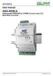
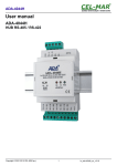
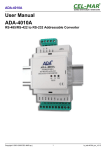
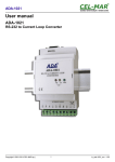
ADA-401W
User manual
ADA-401W
RS-422 to 1-WIRE Converter
Copyright © 2001-2014 CEL-MAR sp.j.
1
io_ada-401w_en_v3.14
ADA-401W
Contents
1. GENERAL INFORMATION...................................................................................................................................................................... 3
1.1. WARRANTED INFORMATION ...................................................................................................................................................... 3
1.2. GENERAL CONDITIONS FOR SAFE USE.................................................................................................................................... 3
1.3. CE LABEL....................................................................................................................................................................................... 3
1.4. ENVIRONMENTAL PRESERVATION............................................................................................................................................ 3
1.5. SERVICE AND MAINTENANCE..................................................................................................................................................... 3
2. PRODUCT INFORMATION..................................................................................................................................................................... 3
2.1. PROPERTIES................................................................................................................................................................................. 3
2.2. DESCRIPTION................................................................................................................................................................................ 4
2.3. APPLICATION................................................................................................................................................................................ 4
2.4. EPROM MEMORY PROGRAMMING............................................................................................................................................. 4
2.5. CONVERSION OF 1-WIRE TO RS-422 STANDARDS................................................................................................................. 5
2.6. ISOLATION..................................................................................................................................................................................... 5
3. INSTALLATION....................................................................................................................................................................................... 5
3.1. ASSEMBLING................................................................................................................................................................................. 5
3.2. CONNECTION TO PC.................................................................................................................................................................... 5
3.2.1. LINE TERMINATION.............................................................................................................................................................. 6
3.3. CONNECTION TO 1-WIRE NETWORK ........................................................................................................................................ 6
3.3.1. CONNECTION 1-WIRE SENSORS....................................................................................................................................... 6
3.3.2. LIMITATIONS OF 1-WIRE BUS............................................................................................................................................. 6
3.4. POWER SUPPLY........................................................................................................................................................................... 7
4. STARTUP................................................................................................................................................................................................ 7
4.1. SIGNALING LEDS.......................................................................................................................................................................... 7
5. VERSIONS.............................................................................................................................................................................................. 7
6. SPECIFICATION..................................................................................................................................................................................... 7
2
ADA-401W
1. GENERAL INFORMATION
Thank you for your purchase of CEL-MAR Company product. This product has been completely tested and is covered by a two year
warranty on parts and operation from date of sale.
If any questions or problems arise during installation or use of this product, please do not hesitate to contact Technical Support at +48
41 362-12-46 or e-mail [email protected].
1.1. WARRANTED INFORMATION
CEL-MAR Company gives the indefinite guarantee on the ADA-401W converter. The warranty does not cover damage caused from
improper use, materials consumption or any unauthorized changes. If the product does not function accordance with the instructions
will be repaired. All warranty and no warranty repairs must be returned with paid transport and insuring to the CEL-MAR Company.
CEL-MAR Company under no circumstances won't be responsible for ensuing damage from improper using the product or as a result
of random causes: the lightning discharge, the flood, the fire and the like.
CEL-MAR Company is not be held responsible for damages and loss including: loss of profits, loss of data, pecuniary losses ensuing
from using or the impossibility of using this product.
In specific cases CEL-MAR Company discontinue all warranties and in particular do not follow the user manual and do not accept
terms of warranty by the user.
1.2. GENERAL CONDITIONS FOR SAFE USE
The device should be installed in a safe and stable places (eg, electroinstallation cabinet), the powering cable should be arranged so
as not to be exposed to trampling, attaching, or pulling out of the circuit.
Do not put device on the wet surface.
Do not connect devices for nondescript powering sources,
Do not damage or crush powering wires.
Do not make connection with wet hands.
Do not adapt, open or make holes in casings of the device!
Do not immerse device in water or no other liquid.
Do not put the fire opened on device sources: candles, an oil lamps and the like.
Complete disable from the supply network is only after disconnecting the power supply circuit voltage.
Do not carry out the assembly or disassembly of the device if it is enabled. This may result to short circuit and damage the device.
1.3. CE LABEL
CE symbol on organizing the company CEL-MAR a conformity of the device to the directive of the electromagnetic EMC
89/336/EWG compatibility means (Electromagnetic Compatibility Directive). The declaration of the agreement is
accessible through the contact with the technical service at the address e-mail: [email protected] or on the phone at
the +48 41 362-12-46.
1.4. ENVIRONMENTAL PRESERVATION
This sign on the device inform about putting expended device with other waste materials. Device should send to the
recycling. (In accordance with the act about the Electronic Appliance Expended from day 29 of July 2005)
1.5. SERVICE AND MAINTENANCE
The ADA-401W converter does not require the servicing and maintenance.
Technical support is available at number +48 41 362-12-46 in 8.00-16.00, from Monday to Friday or e-mail [email protected].
2. PRODUCT INFORMATION
Module is delivered with: User Manual, resistors: Rt=120W (2 pcs.).
2.1. PROPERTIES
●
●
●
●
●
●
●
●
●
●
●
●
●
●
●
●
●
RS-422 conversion to 1-WIRE,
Converted signals: RX, TX,
Possibility of operating on MicroLAN bus,
Possibility of programming EPROM memory on the 1-WIRE bus (version device -2-x-x),
Baud rate of RS-422 bus [kbit/sec]: 9.6, 19.2, 57.6, 115.2,
Standard baud rate of 1-WIRE bus up to 16.3 kbps,
Overdrive baud rate of 1-WIRE bus up to 142 kbps,
External power supply 10 - 30 VDC stable with power min. 3W,
1kV= or 3kV= galvanic isolation between RS-422 interface and power supply,
3kV= optoisolation in signal channel between RS-422 and 1-WIRE interface,
Casing compatible with DIN 43880 standard– mounting in typical electro-installation unit,
Casing adapt to rail mounting according to Dinas EN 50022 standard,
Casing dimensions (W x H x L) 53mm x 90mm x 58mm,
Connection RS-422 interface via screw terminal block,
Connecting 1-WIRE bus and power supply via screw terminal block,
Implemented short circuit protection and over-voltage protection on RS-422 interface line,
Implemented protection against power supply reverse connection,
3
ADA-401W
2.2. DESCRIPTION
RX-
RX+
TX-
TX+
GND
10mm
The ADA-401W industrial converter for general use, allows connection several circuits with1-Wire interface, such as temperature
measurement systems, real time clocks, EPROM, A/C, etc. to a common 1-Wire bus far away from the Master device (up to 1200m).
The transition from the 1-Wire interface to RS-422 interface on ADA-401W, provides system DS2480B and level converter TTL to RS422. This relieves the user from having to be in a quite a complicated 1-Wire protocol.
The using of an additional converter RS-422 to RS-232 (eg, ADA-1040) allows monitoring and / or control systems 1-Wire via RS-232
interface on a PC equipped with the appropriate software. CEL-MAR provides sample applications for the visualization of temperature
measurement named Lämpömittari by Timo Sara-aho. The program works with systems to measure temperature eg DS18S20. In
the configuration settings of Lämpömittariin the section MicroLAN use the symbol DS9097U adapter.
ADA-401W is equipped with screw terminal block for twisted connections of 1-Wire bus and RS-422 and for power supply. Overvoltage protection on each RS-422 line was made on base over-voltage LEDs and fuses.
ADA-401W is designed for power from an external DC voltage source whose value should be in the range of 10V to 30V and it was
supplied from the AC power 3W min. It also has built-in protection against reverse polarity power supply.
(RS422)
90mm
ADA-401W
RS-422 to 1-WIRE CONVERTER
RX
TX
PWR
1-WIRE
V+
NC
GND
1-W
VDD
NC
NC
NC
NC
10mm
V-
10 – 30
VDC
(1-WIRE)
53mm
58mm
Fig. 1. ADA-401W view
2.3. APPLICATION
ADA-401W converter can be used in all kind of local systems based on MicroLAN networks such as: the registration of the
temperature, the monitored access, steering the functioning of air-conditionings of both the heating, the remote control and the
supervision, in alarm, fire systems and the like much moved away from monitoring center. A market of alarm systems is one of most
quickly developing at present markets, which MicroLAN is being used among others for linking in of sensors with the alarm head
office, where in place a few or of a dozen or so wires will only be enough 3. In such applying does MicroLAN prevent the possibility of
cheating through clenching or incising the line and at the same time provides with the alarm system easiness of the automatic
configuration and the reconfiguration of the alarm system during the work. Much also leading test procedures which disabled elements
of the system are helping to eliminate is simpler than in standard solutions.
2.4. EPROM MEMORY PROGRAMMING
ADA-401W converter in version 2-x-x allows to programming EPROM memory added to MicroLAN network. It is done by the use of
micro-switch on the front panel. By setting the micro-switch to PROG position, to the bus should be added programmable circuit and
make the programming. If on the bus are circuits which do not require programming, the micro-switch sould be set to NORMAL
position.
4
ADA-401W
2.5. CONVERSION OF 1-WIRE TO RS-422 STANDARDS
Because of the fairly complex 1-WIRE protocol, ADA-401W converter is equipped with DS2480B circuit, which make easy access to
1-WIRE from a serial RS-422 bus. Communication with device connected to 1-WIRE is sending/receiving the appropriate command
via RS422 interface. Additional description all commands and communication are described in technical documentation DS2480B
circuit, available on manufacturer web page http://www.maxim-ic.com/quick_view2.cfm/qv_pk/2923 or CEL-MAR.
2.6. ISOLATION
Converter ADA-401W has 2-way, 1kV= or 3kV= galvanic isolation (depend on version, described in section VERSIONS).
2-WAY ISOLATION
RS422
1-WIRE
POWER SUPPLY
10 - 30VDC
Fig. 2. Isolation diagram
3. INSTALLATION
This chapter will show how to connect ADA-401W to PC, 422 bus, 1-WIRE line and power supply and how to use it.
To reduce disturbance from environment, it is recommended to:
– use multipair type shielded cables, which shield can be connected to the earthing on one end of the cable,
– use the suitable diameter cable for power supply on account of voltage drop,
– use the powering cable with a suitable section because of the voltage drops,
– use the interference eliminators for powering the converter,
– lay signal cables at a distance of not less than 25 cm away from power cables,
– not powering the converters form the power-circuit of devices generate large impulse disturbance like contactors, relays, inverters.
3.1. ASSEMBLING
ADA-401W converter case is adapted to assembly on TS-35 (DIN35) rail. To install converter should mount device on the rail upper
part of the case then press bottom part to to hearing characteristic „Click” sound.
3.2. CONNECTION TO PC
ADA-401W can be connected to RS232 port or USB of PC by the use of additional converter eg. RS232 to RS485/422 (ADA-1040) or
USB to RS485/422 (ADA-I9140). The connection is made via RS422 bus, as on the figure bellow.
PC
ADA-401W
ADA-I1040
RS232
connector
DB-9M/DTE
RS232
Connector
DB-9F/DCE
(2) Rx
(3) Tx
(5) GND
Tx (2)
Rx (3)
GND (5)
RS485(4W)
9600Bd/8/N/1
RS485 / RS422
connector
Tx+/A
Tx-/B
Rx+
Rt
RxGND
RS422
connector
Tx+
TxRx+
Rx-
Rt
Rt
Rt
1-WIRE
connector
VDD
1-W
GND
.
.
Fig. 3. 4-wire connection of ADA-401W to PC by the use of RS232 to RS485/RS422 converter ADA-I1040
PC
ADA-401W
ADA-I9140
USB
connector
USB
connector
USB
USB
RS485(4W)
9600Bd/8/N/1
RS485 / RS422
connector
Tx+/A
Tx-/B
Rx+
Rt
RxGND
RS422
connector
Tx+
TxRx+
Rx-
Rt
Rt
Rt
1-WIRE
connector
VDD
1-W
GND
Fig. 4. 4-wire connection of ADA-401W to PC by the use of USB to RS485/RS422 converter ADA-I9140
5
ADA-401W
3.2.1. LINE TERMINATION
The application of Line Termination (terminator) Rt = 120 W (ohms) will reduce electrical reflection in data line at high baud rate. It is
not needed below 9600Bd. The Line Termination resistor should be used if the distance is over 1000m @ 9600Bd or 700m @
19200Bd transmission, the resistor can be necessary if there are problems with the transmission correctness. Example connection of
Rt to screw terminal block of RS422 interface ADA-401W are shown on Fig. 3 & 4.
3.3. CONNECTION TO 1-WIRE NETWORK
3.3.1. CONNECTION 1-WIRE SENSORS
Way to link temperature sensor to ADA-401W converter is shown on figure below.
ADA-401W
RS422
Connector
1-WIRE
Connector
Tx+
TxRx+
RxGND
GND
1-W
VDD
V+
V-
GND
DQ
VDD
GND
DQ
VDD
GND
DQ
VDD
VV+
1-WIRE (3W) Bus
DS18B20 Sensor
DS18B20 Sensor
10–30VDC
3W
Power Supply
DS18B20 Sensor
Fig. 5. Sensor connection to ADA-401W converter by 3-wire 1-WIRE Bus
ADA-401W
RS422
Connector
1-WIRE
Connector
Tx+
TxRx+
RxGND
GND
1-W
VDD
V+
V-
GND
DQ
VDD
GND
DQ
VDD
GND
DQ
VDD
VV+
1-WIRE (2W) Bus
10–30VDC
3W
Power Supply
DS18B20 Sensor
DS18B20 Sensor
DS18B20 Sensor
Fig. 6.Sensor connection to ADA-401W converter by 2-wire 1-WIRE Bus
3.3.2. LIMITATIONS OF 1-WIRE BUS
The maximum length of 1-wire bus as layouts producer can be even 400m and the maximum number of sensors can be 500.
However, when building the bus, remember that, each sensor is a shortening of 0,5 meters and 100 meters of cable causes additional
capacity load data line 5nF increasing signal distortion.
1-WIRE bus length and number of sensors will be less and will depend on:
– used cables,
– topology connection,
– quality implementation of connections,
– interference from external electromagnetic fields.
RECOMMENDS:
– application of twisted cables UTP 4x2x0,5,
– powered converter with an individual power supply with good parameters, eg. DR-15-24,
– linear topology of 1-WIRE bus (sensors in a star topology can be converted to linear topology by using Passive 1-WIRE
Bus Splitter ADA-DNB400),
– finishing 1-WIRE bus by sensor,
– connecting unused wires and screen cable to rail PE of electrical installation.
6
ADA-401W
3.4. POWER SUPPLY
The power supply to ADA-40WA should be DC (regulated) from the scope 10 V= to 30V= and nominal power more then 3W eg. DR15-25 or ZS-12/500. The power cable from DC power supplies to the device must not be longer than 3m. Observe the polarity,
connect positive (+) of DC power supplies to V + and negative (-) end to V - terminal.
4. STARTUP
Converter can be powered after proper connection according to steps above. If connection was made properly green LED PWR on
front panel of converter should light, if not check correctness of power connection. ADA401W has the protection against power supply
reverse connection. During correctness data transition via the converter the LEDs Tx and Rx should blinking.
4.1. SIGNALING LEDS
LED
Description
PWR
Signalling of Power Supply
TX
Signalling of data transmitting through 1-WIRE interface
RX
Signalling of data receiving from 1-WIRE 1-WIRE interface
ATTENTION!
At baud rate above 19200 bps the LED's Tx, Rx will light weakly during data transmission.
5. VERSIONS
ADA-401W -
-
-
Electronic versions:
Without possibility of programming 1-WIRE interface
1
With possibility of programming 1-WIRE interface
2
Order example:
Product Symbol: ADA-401W-1-2-3
1 – without possibility of programming 1-WIRE interface,
2 – galvanic isolation 1kV=,
3 – cover without inlets, plug-in screw terminal block,
Galvanic isolation:
1kV=
2
3kV=
3
Terminal & Terminal Cover:
Cover without inlets, screw terminal block
1
Cover with inlets, screw terminal block
2
Cover without inlets, plug-in screw terminal block
3
6. SPECIFICATION
Transition Parameters
Interface
Connector
Line length
RS-422
Maximum baud rate
Transmission type
Standards
Optical signaling
screw terminal, wire max. ø 2,5mm2
1200m
up to 400m – for ds18b20 sensors
1
100
Maximum number of connected device
Transmission line
1-WIRE
screw terminal, wire max. ø 2,5mm 2
Twisted cable 2-pair , UTP Nx2x0,5
(24AWG), shield inside large
interferences STP Nx2x0,5(24AWG).
Twisted cable 1-pair or 2-pair , UTP
Nx2x0,5 (24AWG), shield inside large
interferences STP Nx2x0,5(24AWG).
standard: 0 do 16,3 kbps,
9.6, 19.2, 57.6, 115.2
overdrive: 0 do 142 kbps,
1-WIRE - half duplex (sending and receiving on the same wire)
1-WIRE – TTL signal, EIA-422, CCITT V.11.
• PWR – green LED power supply
• RX - red LED data receiving through 1-WIRE interface
• TX - yellow LED data transmission through 1-WIRE interface
Nominal Operating Conditions
Power requirements
Power Cable
10 - 24 – 30 V DC
Recommended length of power cable – up to 3m
Power
3W
YES
Protection from reverse power polarization
Galvanic Isolation
1kV DC or 3kV DC - between power circuit and RS422 signal line
Optoisolation
3kV - between signal line 1-WIRE and RS-422
7
ADA-401W
Operating temperature
0 ÷ +23 ÷ +50°C
5 ÷ 95% - non-condensing
Humidity
Position during operation
Free
Mounting
Rail mounting according to DIN35 standard / TS35.
Electromagnetic compatibility
Resistance to disruptions according to the standard PN-EN 55024.
Emission of disruptions according to the standard PN-EN 55022.
Safety requiring
According to the PN-EN60950 norm.
Environment
Commercial and light industrial.
Enclosure
Dimensions
53mm x 90mm x 58 mm,
Noryl UL. 94 V-O
Material
Degree of casing protection
IP40
IP20
Degree of terminal protection
Weight
0,10 kg
DIN EN50022, DIN EN43880
According to standard
Storage and transportation conditions
Storage temperature
-40 ÷ +70 °C
5 ÷ 95% - non-condensing
Humidity
Dear Customer,
Thank you for purchasing CEL-MAR Company products.
We hope that this user manual helped connect and start up the ADA-401W converter. We also wish to inform you that we are a
manufacturer of the widest selections of data communications products in the world such as: data transmission converters with
interface RS232, RS485, RS422, USB, Current Loop, Fibre-Optic Converters and Ethernet or Wi-Fi.
Please contact us to tell how you like our products and how we can satisfy you present and future expectation.
Tel.................................................... : +48 41 362-12-46
Tel/fax.............................................. : +48 41 361-07-70
Web................................................. : http://www.cel-mar.pl/en
Office............................................... : [email protected]
Sales department........................... .: [email protected]
Technical information ..................... : [email protected]
CEL-MAR sp.j.
Zakład Informatyki i Elektroniki
str. Ściegiennego 219C
25-116 Kielce, POLAND
8