1
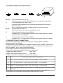
COSTRUZIONE APPARECCHIATURE ELETTRONICHE - OLEODINAMICHE - INDUSTRIALI
42028 - POVIGLIO - (R.E.) Via Parma, 59 - ITALIA
Tel. (0522) 960050 (r.a.) - Tlx. 530021 AINDRE I - Fax (0522) 960259
ZAPIMOS
H1DN
USER's MANU
AL
MANUA
INDEX
Page
Legend
.............................................................................................................. 2
1 Introduction to the ZAPIMOS family ............................................................. 3
2 Characteristics ............................................................................................... 4
2.1 Specifications ............................................................................................ 4
2.2 Control units .............................................................................................. 5
2.2a Microswitches ................................................................................ 5
2.2b Potentiometer ................................................................................ 5
2.3 Speed ........................................................................................................ 7
2.4 Safety devices ........................................................................................... 7
2.5 Performance .............................................................................................. 8
2.6 Thermic considerations ............................................................................. 9
2.7 General advices
.............................................................................. 9
2.8 Susceptibility and electromagnetic emission ............................................. 9
3 Installation .................................................................................................... 10
3.1 Choice connecting cable ......................................................................... 10
3.2 Contactors ............................................................................................... 10
3.3 Fuses ....................................................................................................... 10
3.4 Mechanical drawing ................................................................................. 11
3.5 Connector description .............................................................................. 12
3.6 Power connector description ................................................................... 14
3.7 Description of the connections ................................................................. 14
3.8 Diodes ..................................................................................................... 15
4 Settings ........................................................................................................ 16
4.1 Description of variable parameters .......................................................... 17
4.2 Parameter change via economic console ................................................ 18
4.3 Description of digital console functions ................................................... 19
4.4 Sequence of settings H1DN .................................................................... 20
5 H1DN diagnosis ........................................................................................... 21
5.1 Decoding of the alarms on display ........................................................... 22
6 Schematic diagrams .................................................................................... 25
6.1 Description of H1DN 3 cables 2Q layout ................................................. 25
Connection diagram of H1DN 2Q ( tiller ) ...................................................... 26
Connection diagram of H1DN 2Q ( pedal ) .................................................... 27
6.2 HIDN AUTOSTOP .................................................................................. 28
6.3 Description of H1DN 4 and 3 cables 1Q .................................................. 28
Connection diagram of H1DN 4 cables with changeover contactors
1Q ( tiller ) ...................................................................................................... 29
Connection diagram of H1DN 4 cables with changeover contactors
1Q ( pedal ) .................................................................................................... 30
Connection diagram of H1DN 3 cables 1Q ( tiller ) ........................................ 31
Connection diagram of H1DN 3 cables 1Q ( pedal ) ...................................... 32
Spare parts ......................................................................................................... 33
Periodic Mainteinance........................................................................................ 34
= The informations included into the marked paragraphs by this symbol are essential for
the safety.
Pubblication n°.: 550114B
Ediition: July 1994
Page 1
LEGEND
1Q
2Q
AV
BTA
BTG
BTI
BTP
CH
CL
EF
EV
IN
IND
M.UM
MA
MCL
MD
MEF
MI
MSOL
MT
MU
NT
POT
RV1
TA
TG
TI
VMN
Page 2
=
=
=
=
=
=
=
=
=
=
=
=
=
=
=
=
=
=
=
=
=
=
=
=
=
=
=
=
=
1 Quadrant
2 Quadrants
Forward
Forward contactor coil
General contactor coil
Backward contactor coil
Pump contactor coil
Key
Horn
Electrobrake coil
Electrovalve coil
Reverse
Weakening
Belly switch
Forward microswitch
Horn switch
Down microswitch
Electric brake switch
Reverse microswitch
Lifting switch
Tiller switch
Up microswitch
Contactor minus
Potentiometer
Speed reduction 1
Forward physical contact
General physical contact
Backward physical contact
Motor minus voltage
1 INTRODUCTION TO THE ZAPIMOS FAMILY
The Zapimos chopper family is the solution offered by ZAPI to meet the users’ requirements in the 90’s.
To ensure that the product remain on the market for a sufficiently long period of time
without running the risk of becoming technically obsolete, ZAPI has designed the Zapimos family which features the following specifications:
- Advanced technology
-
Top safety
-
Very high flexibility
-
Possibility of updating based on future technological innovations
-
Very high level of protection.
This includes :
-
High frequency Mos technology
-
Real-time control of inner and outer components which may affect machine
behaviour with self-diagnosis of the control circuits.
-
Recorded program machine (SPC) where the physical component (hardware) is kept
completely separated from the functions to be implemented.
The program is parametric with possibility of intervention on the part of the end user.
-
Any in-house technological updating is made clear to the user.
The communication protocol will evolve over the next few years to offer increasing
possibilities of interaction.
For this purpose the Zapimos family features a dialog mode with standard external
system to be easily interfaced with commercially available machines.
ZAPI also offers a wide range of Programming Consoles with different types of performance and different prices.
-
Logic and power units are fitted in a semi - enclosed case (IP54) to ensure protection
against splashes (water, acid, etc.), dust, chips and smallware.
Access to the logic unit remains very easy allowing for quick replacement or
inspection.
H1DN is the smallest chopper of this family. It is suitable for operation on voltage
24V with motors in the range 500W to 2KW. An interesting option is a completely
static version with 3-cable motors.
Page 3
2 CHARACTERISTICS
2.1 SPECIFICATIONS
Chopper H1DN is suitable for controlling 3 and 4 terminal series wound motors.
Frequency
:
18 KHz
Voltage
:
24V (16 - 30)
Max Current
:
2 Quadrants - 150A for 4 min.
1 Quadrant - 300A for 2 min.
Temperature
:
-30° : +40°C
CONFIGURATION
CURRENT
CONTACTORS
DIODI
FRENO
DROP VOLTAGE
(1/3 IMAX)
3 CABLES 2Q
150A
GENERAL
NO
200mV
3 CABLES 1Q
300A
FW - REV
SI
200mV
4 CABLES 1Q
300A
FW - REV
SI
200mV
3 CABLES 2Q
Page 4
3 CABLES 1Q
4 CABLES 1Q
2.2 CONTROL UNITS
2.2a Microswitches
Microswitches send a voltage signal when a direction request or a desired function is
activated. The tiller microswitch or the dead man microswitch conduct the current to exite
the contactors and the electrobrake. They should be able to handle currents up to 5
amps. For safety reasons it is mendatory to use this microswitch according to the
reported diagrams. To stop the chopper there are 4 possible levels:
1. Chopper opens up the contactors automatically through its safety features in a time
shorter than 100 msecs.
2. Open of tiller microswitch or dead man microswitch
3. Key
4. Battery connector
3. and 4. are always of easy access, so that the use of the tiller microswitch gives an
effective alternative way to stop the chopper. When the key is turned on this microswitch
should be open so that the microprocessor is able to verify its status every time that
power is supplied to the chopper.
2.2b Potentiometer
It can be connected in both 2 or 3 wire configurations.
The signal on CPOT (C1) ranges from 0 to 5 volts. In order to have a correct functioning
of the 2-wire configuration a 20 Kohm trimmer is present on the logic board. This trimmer
is placed between the CPOT (C1) connector and the 13V5 internal power supply. This
enables to adjust the signal to different potentiometer values.
In the 2-wire configuration the end of stroke value should range from 300 ohm to 10
Kohm. In the 3-wire configuration the end of stroke value should range from 500 ohm to
10 Kohm Lower values overload the power supply unit, higher values make it possible
linearity errors.
The procedure for automatic potentiometer signal acquisition is carried out from the
console. This makes it possible to adjust the minimum and maximum useful signal in the
respective directions.
This function is indispensable when it is necessary to compensate for asymmetry in the
mechanical workings that control the potentiometer, especially as regards the adjustment of the minimum which in certain cases, if made in the traditional way, requires a
calibration that is laborious and costly, but very often gives unsatisfactory results.
The sequence of procedures is described in the programming console manual.
Page 5
fig. 8a
fig. 8b
The two graphs show the output voltage from an uncalibrated potentiometer with respect
to the mechanical “zero” of the knob of one handle (MI and MA indicate the point at
which the speed microswitches close, 0 is the mechanical zero of the handle rotation).
The first graph (Fig. 8a) shows the correspondence of the motor voltage without having
made the acquisition, while the second graph (Fig. 8b) shows the same correspondence
after signal acquisition by the potentiometer.
The acquisition procedure is invalidated by the machine if the difference between the
maximum value and the minimum value is less than 2V.
This acquisition procedure makes it possible:
- to use “reversed” potentiometric signals, i.e. those which are carried from a high
initial value to a low final value.
-
to use a normal potentiometer instead of one with central zero.
For the correct functioning of signal acquisition, it is absolutely necessary that the running microswitches be activated by the same shaft that moves the potentiometer.
Application examples.
- Signal overturn.
VACC = accelerator signal voltage to pin C1.
VMOT = percentage of battery voltage on the motor.
Page 6
2.3 SPEED
Speed may be adjusted:
- Max. speed adjustment from 10 to 100% ( via the programming console only ).
-
Speed reduction device with microswitch go-ahead: RV1 ( from 10 to 100% ).
-
Speed reduction device with microswitch go-ahead: RV2 ( from 10 to 100% ).
When one of the three reduction devices is in automatic function the chopper adjusts the
voltage to keep speed constant.
The feed - back parameter can be changed from the console to obtain the desired
characteristic.
2.4 SAFETY DEVICES
-
Battery Inversion
Abready present in the 3-cable version with general contactor; In other versions
there should be a main contactor which isolates +Batt (optional).
-
Connection errors
All inputs are protected against connection errors except for inputs NT1 and NT2
which do not accept direct connections with +Batt or loads greater than 3A.
-
Thermal protection
If temperature exceeds 75°C the max. current is reduced proportionally to the temperature rise.
Temperature is never allowed to exceed 85°C.
-
Discharged battery
If the battery is down discharged, max. current is reduced by 50%.
-
External agents
The chopper is protected against dust and fluid splashes (IP54) as it is semi
enclosed.
Page 7
-
Safety against accidental starting
A precise sequence of operations is required to start the machine. If such operations
are not correctly performed the machine will not start.
They are as follows:
1) -
Handle microswitch
-
Running microswitch
2) -
Key
Key
Seat microswitch ( 5sec. delayed )
Running microswitch
Safety against uncontrolled movements
Contactors will not close if:
- The power unit is not operating.
- The accelerator is not allowed to reach below 1 Volt.
- The logic unit is not operating correctly.
- One of the running microswitches is closed.
- Request for rapid inversion is available independently of the running microswitches.
2.5 PERFORMANCE
-
Very good sensitivity at low speed
-
Anti-Roll-Back
-
Rapid inversion
-
Braking with current control
-
Electric brake coupling
-
Field weakening or bypass control with adjustable output current.
-
Diagnosis with failure indication by means of an optional LED.
-
Parameter adjustment via the console (see specific paragraph).
-
Internal hour meter suitable for being displayed on the console.
-
Storing of the last 5 alarms which have occurred with the corresponding hour meter
values which can be displayed in the console and chopper temperature.
-
Tester function via the console to check main parameters in real time, i.e. inputs,
motor voltage and battery voltage.
-
The function " DATA MOTOR " optimizes the motor chopper combination,
registering the relevant characteristics of the motor that influences the electric
braking.
Page 8
2.6 THERMAL CONSIDERATIONS
-
The heat generated by the control unit must be dissipated. For this to be possible,
the compartment must be ventilated and the cooling surfaces ample.
-
The cooling system is dimensioned on the basis of the performance required of the
machine. For situations in which ventilation is poor and heat exchange difficult
because of the materials used, it is advisable to use forced air ventilation.
-
The power dissipated by the module varies depending on the current and the work
cycle.
2.7 GENERAL NOTES AND PRECAUTIONS
-
Never combine SCR low frequency choppers with H1DN modules, as the filtre
condensers contained in the H1DN module alter SCR chopper functioning,
subjecting it to excessive workloads. Thus, if you wish to use two or more control
units (e.g. lift + traction), they must all be of the high frequency ZAPIMOS family.
-
Do not connect the chopper to a battery with a different nominal voltage than that
indicated on the chopper identification plate. A higher battery voltage can cause
MOS failure. A lower battery voltage prevents the module from functioning.
-
During battery recharge, the H1DN module must be completely disconnected from
the battery, as in addition to altering the charge read by the battery charger, the
module can be damaged by the overload voltages generated by the charger.
-
The H1DN module must only be supplied using a traction use battery; do not use
outputs of straighteners or power suppliers. For special applications, consult the
nearest ZAPI service centre.
-
Start the machine the first time with the wheels raised, to ensure that connection
errors do not create safety risks.
-
With the key off, the filtre condensers inside the module may remain charged for
several minutes. For safe operation, we recommend that you disconnect the battery
and short circuit the power positive and negative on the chopper for a few seconds
with a resistance of between 10 ohm and 100 ohm.
2.8 SUSCEPTIBILITY AND ELECTROMAGNETIC EMISSION
The electromagnetic susceptibility and emission are remarkably influenced by the
modality of installation; a special attention must been put on the lenght and the paths of
the electric connections and the shields.
Therefore ZAPI declines any responsability regarding the bad-working imputable to
above-mentioned cases, especially if the truck's builder doesn't execute the required test
from the norm in force. (The emission conducted, the irradiated emission, IEC 801-2
(ESD), IEC 801-3 (irradiated susceptibility), IEC 801-4 (BURST), IEC 801-5 (SURGE),
IEC-6 (the immunity conducted).
Page 9
3 INSTALLATION
Fit the chopper with its base plate on a flat, unpainted, clean, metal surface.
Apply a thin layer of thermoconductive grease between the two surfaces to ensure
optimum heat dissipation.
Even if protection is available against external agents the continuous attack by corrosive
agents may cause oxidation of the connector contacts thereby impairing their operation.
This factor should be kept well in mind when selecting the location of the chopper within
the vehicle.
To fix the chopper, use the suitable holes available in the base plate.
Check that cable terminal and connector cabling has been accurately performed.
It is recommended to fit suppression elements to the horn, solenoid vales, and all
contactors not connected to the chopper.
3.1 CHOICE OF CONNECTING CABLES
For auxiliary circuits use cables with 0.5 mm² cross section area.
For power connections to the motor and battery in the 2 Quadrant versions use cables
with 16-25 mm² cross section while in the 1 Quadrant versions use cables with 25-35
mm² cross section area.
To increase the chopper performance, the cables connecting to the battery should be as
short as possible and laid next to each other.
3.2 CONTACTORS
Contactors should be selected based upon on the motor max. operating current and on
the configuration.
- The current absorbed by the coil should not exceed 3A.
-
Coil suppression is internal to the logic. Do not use contactors with suppression
elements connected.
-
In the case of contactors using magnetic suppression on the contacts, check polarity
as shown on the cap.
3.3 FUSES
-
To protect auxiliary circuits use a fuse with max. 6.3A.
-
To protect the power unit see diagrams.
The indicated value is the max. permissible value. For special applications or
requirements this value can be reduced.
For safety reasons it is recommended to use protected fuses in order to avoid
particle dispersion in case of blowout.
Page 10
3.4 CHOPPER H1DN MECHANICAL DRAWING
Page 11
3.5 CONNECTOR DESCRIPTION
Pos. Function
A1 LED
Description
Alarm Led minus: to be connected to the cathode.
A2
Alarm Led plus: to be connected to the anode.
+LED
Output current 12mA for standard Led.
B1
PCLRXD
Serial reception plus.
B2
NCLRXD
Serial reception minus.
B3
PCLTXD
Serial transmission plus.
B4
NCLTXD
Serial transmission minus.
B5
GND
Console supply minus.
B6
+12
Console supply plus.
B7
FUN. SEL.
Economic console channel.
B8
UP/DOWN
Economic console channel.
C1
CPOT
Potentiometer central: to be connected to the potentiometer slider.
For speed adjustment the useful signal ranges from ØVolt (lowest
speed) to 5Volt (highest speed).
C2
NPOT
Potentiometer minus: This is a battery negative.
C3
PPOT
Potentiometer plus: This is a 12Volt output. It is not used if the
potentiometer is wired with 2 cables.
Do not short this terminal to battery negative and do not apply a
resistance load of less than 500ohm.
D1
+ Key
To be connected to key switch return.
D2
IR
Signal for handle safety device activation.
(spare / free)
The safety device is activated with opened microswitch or if the
applied voltage is less than 12Volt. If not used it can be wired to
Key positive or disconnected from the programmable console.
Page 12
E1
TILLER / SEAT Input whose function should be defined from the console (or re
Free
quested at the time of order).
Its configuration can be a handle or seat microswitch (5 sec
delayed) signal input; otherwise it can remain unused.
The function is activated if the level is brought to a value greater
than 12Volt.
E2
//
Not used.
E3
NT2
Energises the field weakening or bypass contactor.
It provides connection to B- ' ve when active (Max. 3A).
E4
RV2
Input for speed reduction operation (RV2).
(spare, free)
If connected to a potential of more than 12Volts, reduction is
inhibited.
If left free or connected to B-' ve it performs the reduction function
operates. Activation of this input can be programmed from the
console.
RV1
Input for speed reduction operation (RV1).
(spare, free)
If connected to a potential of more than 12Volt reduction is
inhibited while if left free or connected to Battery negative, the
reduction function operates. Activation of this input can be
programmed from the console.
IN
Selects reverse.
E5
E6
It should be connected to the reverse microswitch and activates the
contactor when greater than 12Volts.
E7
AV
Selects forward.
It should be connected to the forward microswitch and activates the
contactor when greater than 12Volts.
E8
NT1
It operates the main contactor or the running contactors.
When active it provides connection to B-' ve.
E9
/
Not used.
Page 13
3.6 POWER CONNECTOR DESCRIPTION
B +' ve
To be connected to the B+' ve.
It is a power circuit positive which thus does not supply the control logic.
1
To be connected to the motor ( rotor ).
It provides a direct positive from the battery down stream of the current
measuring circuit.
Do not connect this terminal to loads other than the traction motor.
B-' ve
It is connected to the B-' ve.
This feed is also common to the control logic circuit.
2
It is the forward direction driver (VMNA).
It supplies a B-' ve via a mosfet circuit when the forward direction is active.
For connections see diagrams.
3
It is the reverse direction driver (VMNI).
It supplies a B-' ve via a mosfet circuit when the reverse direction is active.
3.7 DESCRIPTION OF CONNECTIONS
The choices concerning the power unit and some auxiliary signals should be
programmed into the chopper.
In the absence of this information the chopper sends an alarm (ALARM 1) and will not
operate. To provide this information, simply connect the chopper to the console and
enter the specific menu (see console description).
The available standard configurations are as follows:
Power unit configurations programmable from the console.
3 cables with main contactor
:
max. 150A.
4 cables with remote-control inverter :
max. 300A.
Auxiliary inputs with configuration made from the console:
INPUT
STATES SELECTABLE FROM THE CONSOLE
E5
RV1 0 = CUT BACK SPEED 1°, FREE = NOT USED, SPARE = TO BE DEFINED
E4
RV2 = CUT BACK SPEED 2°, FREE = NOT USED, SPARE = TO BE DEFINED
D2
INVERS = RAPID INVERSION, FREE = NOT USED, SPARE = TO BE DEFINED
E1
SEAT = SEAT MICROSWITCH DELAY, HANDLE = HANDLE MICROSWITCH, SPARE = TO BE
DEFINED
Depending on the customer’s request, the chopper is supplyed comes with its
configuration and name-plate indicating the model and max. current.
Page 14
3.8 DIODES
In 1 Quadrant versions for 4 or 3 cable motors external diodes should be fitted to allow
for adjustable braking.
Upon customer’s request ZAPI will supply the system with a module containing easily
connecting diodes both for the 4 cable and 3 cable versions.
Page 15
4 SETTINGS
Similarly to chopper configuration, parameter settings can be directly made at ZAPI
according to the customer’s specifications or by the customer via the programming console or the economic console which allows changes only to the parameters indicated
with an asterisk*.
The chopper parameters shown below can be changed between ten intermediate levels
within the specified range:
PRO G RAM M ED LEVEL
PA R A M E T E R
U N IT
0
1
2
3
4
5
6
7
8
9
A C C E L E R AT IO N D E L AY *
S ec.
0 .3 8
0 .6 6
1
1 .3
1 .5
1 .8 4
2 .1 7
2 .5
2 .8
3
B R A K IN G (C P O T = M A X )*
% IM a x .
50
58
66
73
81
89
96
104
112
120
C U T B A C K (1 -2 )*
% V B a t t.
16
20
2 5 .6
3 4 .6
43
4 8 .5
5 3 .5
6 2 .6
65
76
C O M P E N S AT IO N
K ( I)
0
0 .1
0 .2
0 .3
0 .4
0 .5
0 .6
0 .7
0 .8
0 .9
CREEP SPEED*
% V B a t t.
2 .5
6 .9
9 .2
1 1 .7
14
1 6 .3
2 0 .8
22
25
30
IM a x . 2 Q
A m p.
75
83
92
100
108
117
125
133
142
150
IM a x . 1 Q
A m p.
150
167
183
200
217
233
250
267
283
300
M a x . S P E E D (F -B )
% V B a t t.
7
9 .3
20
30
3 9 .2
4 8 .4
60
65
74
C T.
R E L E A S E B R A K IN G
% IM a x .
-
18
27
36
45
54
63
72
81
90
The console can be kept constantly connected to the chopper and parameters may be
changed in real time during operation.
The parameters set and optimized can be recorded via the console (SAVE) and then reloaded (RESTORE) into another chopper thereby making it possible to obtain rapid and
standard settings (see console manual for further details).
The logic unit inside the chopper features a trimmer for adjusting the max. value of the
potentiometer if it is connected to 2 wires. To perform setting remove the upper cover,
connect a tester for voltage measurement between the CPOT and NPOT connectors,
bring the potentiometer control unit to max. stroke and rotate the logic unit trimmer until
a voltage of 4.8 - 4.9Volt is read.
With the programming console this operation is made easier in that the value is read
directly on the display.
Page 16
4.1 DESCRIPTION OF VARIABLE PARAMETERS
Acceleration delay
Braking
Cut back speed 1
Cut back speed 2
Compensation
Creep speed
IMax.
Max. speed forward
Max. speed reverse
Release braking
=
=
=
=
=
=
=
=
=
=
Acceleration
Braking
Speed 1 reduction
Speed 2 reduction
Compensation
Lowest speed ( First ramp )
Max. current
Highest speed forward
Highest speed reverse
Braking current when direction selector is released.
Page 17
4.2 PARAMETER CHANGE VIA ECONOMIC CONSOLE
The parameters which can be changed are as follows:
1
CREEP SPEED
2
ACCELERATION DELAY
3
BRAKING
4
CUT BACK SPEED 1
5
CUT BACK SPEED 2
0
NOT CONNECTED
Adjustments are possible within the range specified on Page 19 at 10 intermediate
adjustment levels.
- Connect the economic console to the chopper ( B ) connector ( this operation should
be performed when the machine is off ).
-
Riconnect the battery, switch on the machine by turning the key.
-
Position the rotating selector to the function requiring change.
By pressing the SET-UP button the parameter value can be increased while
pressing the SET-DOWN button the same value can be decreased.
Warning! Changes are made by counting the number of pulses sent by the push
buttons. Therefore to increase or decrease one parameter by several points you
should release and press the button again as required.
Keeping a push-button continuously pressed does not allow you to obtain
continuous parameter variation.
-
Parameter variation occurs in real time making it possible to immediately check the
set values.
Page 18
4.3 DESCRIPTION OF DIGITAL CONSOLE FUNCTIONS
-
Power configuration
: H1DN 3 cables 2Q.
H1DN 4 cables-T 1Q.
-
Input configuration
: RV1, RV2, IR, SP
-
Parameter programming
: Acceleration
Braking
Cut back speed 1
Cut back speed 2
Compensation
Creep speed
Max. current
Max. speed forward
Max. speed reverse
Release braking
-
Tester
: VMNA
VMNI
T1 and T2 driver
IN, AV, RV1, RV2, SP, IR inputs
Accelerator voltage
Current
Temperature
Battery voltage
Motor voltage
-
Display of stored alarms
-
Internal hour meter
-
Accelerator stroke programming, forward and reverse
-
SAVE function (data storage)
-
Restore function (parameter loading onto a chopper)
-
Motor Data
See console manual for details.
Page 19
4.4 SEQUENCE OF SETTINGS H1DN
-
With the machine switched off, connect the programming console and then switch
on. If no wiring errors or component defects are found, the display shows the
manufacturer’s name, programme release, configuration, and hour-metre value.
If the module has already been configured, the procedure passes directly to step two.
Otherwise, proceed in order as follows.
Consult the console manual for further procedure details.
1) Configure the chopper model.
2) Select the desired options.
3) Check the functioning of all the wired inputs, including the potentiometer, by means
of the tester functions on the console.
4) Carry out accelerator signal acquisition on the “PROGRAM VACC” menu.
5) Set the maximum current by selecting the level corresponding to the desired value
shown on the table of modifications (pages 16).
6) Set accleration by moving the machine forward and backward.
7) Set the CREEP speed starting from level 0. With the machine stopped, press the
pedal lightly in order to trip the running microswitch, leaving the potentiometer at the
minimum value, and then raise the level of the CREEP until the machine begins to
move.
8) To set the speed reductions, activate the desired reduction request microswitch, take
the compensation level to 0, set the speed (CUTBACK SP.l, etc.) with machine in
standby on a flat surface and the acclerator pedal pressed all the way down.
Then, apply a load on the machine or put it on a slope, and in these conditions set
the compensation level until you reach the desired speed.
9) RELEASE BRAKING is set by running the machine and then completely releasing
the accelerator pedal without pressing other pedals.
10) For BRAKING, run the machine and invert the direction with the pedal pressed
down, then regulate the braking level.
Page 20
5 H1DN DIAGNOSIS
Description of the alarms signalled by the diagnostic LED.
The alarm code is shown in parentheses. A detailed description is given in the section
“DECODING THE ALARMS DISPLAYED ON CONSOLE” on page 18÷19.
1 BLINK = Logic anomaly (EEPROM DATA KO, EEPROM PAR. KO, EEPROM
CONF. KO, EEPROM OFF-LINE, CHOPPER NO CONF,
WATCH-DOG).
2 BLINKS
= Running request on startup or error in handle/speeds sequence (INCORRECT START).
3 BLINKS
= Error on VMN test (NO FULL COND, VMN BACK LOW,
VMN FORW LOW).
4 BLINKS
= Accelerator high in standby - this error inhibits operation
(VACC NOT OK).
5 BLINKS
= Error in reading current - this error inhibits operation
(1 HIGH AT STAND, I=0 EVER).
6 BLINKS
= Malfunctioning of the contactor driver circuit (CONTACTOR DRIVER).
7 BLINKS
= Excessive temperature, greater than 75° (TH. PROTECTION).
8 BLINKS
= Contactors do not close (CONT. DONT CLOSE).
CONTINUOUS BLINKING (32 BLINKS) = Low battery charge, battery with <10% of
residual charge (BATTERY).
LED REMAINS ON = Double running request (FORW BACK).
Page 21
5.1 DECODING ALARMS DISPLAYED ON THE CONSOLE
1) CHOPPER NO CONFIG.
This alarm appears if there has not yet been logic unit configuration. In this case
apply the model and input configuration procedure as described in the relevant
paragraph of the console manual. The alarm is blocking.
2) VMN FORW LOW.
The test is performed at rest. An alarm is sent if VMN forward voltage (terminal 2) is
found to be less than 1/3 of battery voltage.
Possible causes:
a) In 2 Quadrant configurations check that stator cabling is correct and that there
are no interruptions.
b) Check that motor has no frame fault.
c) In 1 Quadrant configurations with bypass check that bypass contacts are not
welded close.
d) Chopper out of order, replace.
3) VMN BACK LOW.
See Item 2.
4) NO FULL COND.
The test is performed under full conduction.
If in this condition it turns out that VMN is more than 1/3 of battery voltage something
is wrong in the diagnostics circuit thus impairing safety. For this reason the machine
stops operating.
It this fault persists replace the logic unit.
5) CONT. DONT CLOSE
This test is performed with an operating request.
It should be checked that the contactor closes and that VMN is greater that 2/3 of the
battery voltage. If not an alarm is sent.
Possible causes:
a) Main or running contactor disconnected or faulty, isolated contacts.
b) Isolated or interrupted motor.
c) Chopper power unit failure, replace.
6) I=Ø EVER
This test is performed during operation.
It should be checked that current during operation is greater than a minimum given
value. If this is not the case an alarm is displayed and the machine stops.
Possible causes:
a) Incorrect motor connection. For example, the rotor may have been connected
to the chopper (+B) terminal instead of terminal ( 1 ).
b) The current sensor has failed, replace power unit.
Page 22
7) I HIGH AT STAND
This test should be performed at rest. It should be checked that current is equal to
zero. If this is not the case an alarm is displayed and the machine stops.
Possible causes:
a) Terminal ( 1 ) has been connected to a load other than the driving motor, e.g.
to the pump motor or auxiliary loads.
b) The current sensor or the logic unit may have failed.
Replace the logic unit first. If faulty operation persists change the power unit.
8) WATCH-DOG
This test is performed both at rest and during operation.
It is self-diagnosing within the logic unit.
Replace the logic unit in case an alarm is displayed.
9) FORW-BACK
This test is always performed. An alarm is displayed if two running requests are
simultaneously available.
Possible causes:
a) Faulty cabling
b) Failed running microswitch
c) If faulty operation persists replace the logic unit.
10) INCORRECT START
Incorrect starting sequence.
The machine starts only if the key - handle (or seat) - run sequence is followed.
Possible causes:
a) Failed running or handle microswitch.
b) Incorrect operator’s sequence.
c) Incorrect cabling.
11) VACC NOT OK
This test is performed at rest.
The alarm shows that the accelerator voltage is greater than 1 Volt.
Possible causes:
a) One potentiometer wire has become disconnected.
b) The potentiometer is not calibrated.
c) The potentiometer is faulty (interrupted).
12) CONTACTOR DRIVER
This test is performed both at rest and during operation. It should be checked that the
voltage on the drivers which control contactors is in line with the running state.
High at rest, low during running. With the console tester function check which driver,
whether T1 or T2, is in the correct running ( Ø ) or resting ( 1 ) state.
Possible causes:
a) External short-circuit towards -Batt of the cabling coming from NT1 or NT2.
b) Driver failure due to overloading or short-circuit to +Batt of the cabling from NT1 or
NT2. Replace the logic unit after performin troubleshooting.
Page 23
13) EEPROM DATA KO
Failure in the memory area which contains the hour meter and motor data as well as
the stored alarms. The alarm is blocking.
When switching the key on and off, if the alarm is still displayed replace the logic
unit.
If the alarm disappears please remember that the hour meter starts again from zero,
the alarm area is cancelled and the motor data contains default data.
14) EEPROM PAR.KO
Failure in the memory area which contains the setting parameter data.
The alarm is blocking.
When switching the key on and off, if the alarm is still displayed replace the logic
unit. If the alarm disappears please remember that the hour meter starts again from
zero, the alarm area is cancelled and the motor data contains default data.
15) EEPROM CONF.KO
Failure in the memory area which contains the data for chopper configuration.
The alarm is blocking. Move to the configuration phase and perform chopper
re-configuration.
Subsequently switch off and on again. If the failure persists replace the logic unit.
16) EEPROM KO
Failure in the memory chip. Replace the logic unit.
The alarm is blocking.
18) TH PROTECTION
It indicates that chopper temperature has exceeded 75°C.
Max. current is progressively reduced until a zero value is reached at the temperature of 85°C.
If the alarm is displayed while the machine is in cold state:
a) Check thermal sensor connection
b) Faulty thermal sensor
c) Interrupted power unit connection
d) Faulty logic unit
19) BATTERY
Battery is dis-charged.
When the alarm is displayed the machine stops. At this stage start again with
renewed running request.
Max. current is reduced by 50%.
Page 24
6 SCHEMATIC DIAGRAMS
6.1 DESCRIPTION OF H1DN 3 CABLES 2Q LAYOUT
Configuration with console:
Select the model 3C:
PIN SELECTION
DIS. 072395B
DIS. 072398B
5E
RV1
RV1
4E
RV2
RV2
2D
INVERS
INVERS (FREE SE IR NON COLLEGATO)
1E
HANDLE
SEAT
3E
FREE
FREE
Characteristics:
Max. current 150A.
Static change of the running direction.
The main contactor closes the first time that there is a 4 operating request and opens
when the handle is at rest.
Speed cut-backs are active when microswitches are open.
Page 25
Page 26
Page 27
6.2 HIDN AUTOSTOP
Standard HIDN performs release braking function. This mean that when throttles or the
pedal is released the HIDN chopper performs a braking with a reverse flowing current.
The intensity of this brakaking is adjustable by the RELEASE BRAKING parameter in
the consolle. By setting the RELEASE BRAKING parameter at zero the Atostpo function
is not performed, therefore the chopper behavies as a standard controller (with no autostop function).
6.3 DESCRIPTION OF H1DN 4 AND 3 CABLES 1Q LAYOUT
Configuration with consolle:
Select the model: 4C-T.
PIN SELECTION
DRWG. 072399B
DRWG. 072400B
DRWG. 072445B
DRWG. 072446B
5E
RV1
RV1
RV1
RV1
4E
RV2
RV2
RV2
RV2
2D
INVERS
FREE
INVERS
FREE
1E
HANDLE
SEAT
HANDLE
SEAT
3E
BY. PASS
BY. PASS
/
/
Characteristics:
Max. current 300A.
Running direction is changed only via the contactors.
Braking diodes should be fitted as per diagram in order to obtain chopper-controlled
braking.
Speed cut-backs are active when microswitch contacts are open.
When throttle or pedal is released the HIDN chopper performs a braking with a reverse
flowing current. The intensity of this brakaking is adjustable by the RELEASE BRAKING
parameter in consolle. The AUTOSTOP braking can be performed if the motor reaches a
certain minimum speed.
In the 3-cable version the power interconnections should be modified as shown in drawings
#'s 072399B & 072400B.
Page 28
Page 29
Page 30
Page 31
Page 32
RECCOMENDED SPARE PARTS
Code
E07008
C22000
C16504
C16530
C16503
C16502
C16520
C16530
C12373
C12371
C12370
C12769
C12204
C12203
C12205
C12768
C12230
C12229
C12228
C12767
C29520
C29548
Description
Potentiometer 5 kohm 25°
Microswitch 10A 250V 1-way
Protected power fuse 300A
Protected power fuse 250A
Protected power fuse 200A
Protected power fuse 160A
Glass 5x20 fuse 6.3A
Protected power fuse 250A
9-way molex female connector
3-way molex female connector
2-way molex female connector.
Female connector (molex)
9-way female lock connector
6-way female lock connector
4-way female lock connector
Male connector (for female lock)
9-way male lock connector.
6-way male lock connector.
4-way male lock connector.
Female connector (for male lock)
Albright contactor 24V SW 88-1
Albright simple contactor 24V SW 80 B-1
Page 33
PERIODIC MAINTEINANCE TO BE REGULARLY REPEATED
Check outwear of electric contacts: they should be replaced when matchboard
is too strong and wornout. Electric contacts should be checked every 3
months.
Check pedal microswitch: verify with a tester that there is no electric resistance
between the contacts by measuring the voltage drop between its terminals.
Also the release should have a firm sound. The pedal microswitch should
be checked every 3 months.
Check motor-battery power links: they should be in excellent shae as well as
the wires' claddings. Wires should be checked every 3 months.
Control of the pedal and contactors springs. They should be able to extend to
its full extention and checked every 3 months.
Check contactors mecanical movements. They should be frictionfree and not
stick. Mechanical movements of the contactors should be checked every
3 months.
CHECKS SHOULD BE DONE BY SKILLED PERSONNEL ONLY AND, ALL SPARE PARTS
SHOULD BE ORIGINAL.
INSTALLATION OF THIS ELECTRONIC CONTROLLER SHOULD BE DONE ACCORDING TO THE
DIAGRAMS INCLUDED IN THIS MANUAL AND ANY VARIATION SHOULD BE DONE
ACCORDINGLY WITH THE SUPPLIER. THE SUPPLIER IS NOT RESPONSIBLE FOR ANY
PROBLEM THAT ROSE FROM USING WIRING SOLUTIONS DIFFERENT FROM THE ONES
SUGGESTED ON THIS MANUAL.
DO NOT USE A VEHICLE WITH A
FAULTY ELECTRONIC CONTROLLER
Page 34