1
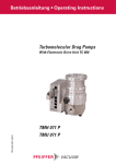
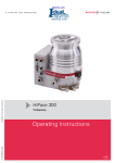
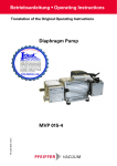
Operating Instructions
Connection Box
PT 0045 BE/C (0303)
TCS 010
Contents
Page
Page
1. Safety Precautions .................................. 3
4. Maintenance, Service ............................. 9
2. Understanding The TCS 010.................... 4
5. Technical Data ......................................... 9
2.1. For Your Orientation........................................................... 4
5.1. Data List TCS 010................................................................ 9
2.2. Product Description........................................................... 4
5.2. Dimensions Diagram TCS 010 .......................................... 9
Proper Use TCS 303 ........................................................... 4
Improper Use ...................................................................... 4
2.3. Description Of The Connections...................................... 5
6. Accessories ........................................... 10
Declaration Of Conformity ...........Annex 1
3. Installation TCS 010................................. 5
3.1. Preparations For Installation............................................ 5
3.2. Ambient Conditions............................................................ 5
3.3. Connection Diagram TCS 010/TC 100.............................. 6
3.4. Connection To The TC 100 ............................................... 6
3.5. Voltage Supply.................................................................... 6
3.6. Connecting The Air Cooling ............................................. 6
3.7. Connecting The Vent Valve ...............................................6
3.8. Connecting The Heating ................................................... 6
3.9. Connecting The Backing Pump .......................................7
3.10. Connecting The RS485 Serial Interface ..........................7
3.11. Connecting The Remote Control...................................... 7
Pin Arrangement And FunctionOf The Plug X3* .......... 8
1. Safety Precautions
Pictogram Definitions:
WARNING
CAUTION
PLEASE NOTE
☞
☞ Read and follow all the instructions in this manual.
☞ Inform yourself regarding:
- Hazards which can be caused by the unit,
- Hazards which can arise in your system,
☞ Comply with all safety and accident prevention
regulations.
☞ Check regularly that all safety requirements are being
complied with.
☞ Do not carry out any unauthorised conversions or
modifications on the unit.
☞ Only connect the right plugs.
☞ Take account of the ambient conditions when installing
the TCS 010. The protection type is IP30.
The unit is protected against the ingress of foreign bodies
ø 2,5 mm.
☞ When returning the unit to us please note the shipping
instructions (please see Section 6).
Danger of personal injury.
Danger of damage to the unit or system.
Attention to particularly important information
on the product, handling the product, or to a
particular part of the documentation.
Please note
Current operating instructions are available via www.pfeiffer-vacuum.net under “Products".
2
2. Understanding The TCS 010
2.1. For Your Orientation
Operating Instruction In The Text
➡ Here you have to do something.
2.2. Product Description
The TCS 010 is a connection box. It serves, in conjunction
with the Electronic Drive Unit TC 100, to control the air cooling
system and the venting valve. Alternatively it is also possible
to connect a heating unit or a backing pump relay box (please
see Section 10, "Accessories"). The Operating And Display
Unit DCU or a PC can be connected via Serial Interface RS
485.
TCS 010
Proper Use
– The TCS 010 may only be used in conjunction with the
TC 100 and original accessory parts.
The TCS 010 connection box serves, in conjunction with the
Electronic Drive Unit TC 100, to control and monitor Pfeiffer
Pumping Stations and Turbopumps.
– The Electronic Drive Unit TC 100 is required for the control
of the turbopump, the venting valve, the air cooling unit,
the TMP heating unit and the backing pump relay box.
– All installations, commissioning and maintenance instructions must be observed.
Improper Use
The following is regarded as improper:
– The use for purposes which deviate from the above and, in
particular:
– The connection to pumps and components which is not
permitted in the operating instructions for those units;
– The connection to components which contain
touchable, voltage carrying parts.
No liability or guarantee claims will be accepted where
improper use is involved.
Delivery Consignment
The following components are included on delivery:
- TCS 010
- 2 fitting screws M3 x 60 mm
3
2.3. Definition Of The Connections
Connection to the power supply (via power supply
TPS)
X3* input plug, 15 pole
TCS 010
Connection power supply TPS
or operating and control unit DCU 100/150
and remote control
X3*
TCS 010
Outputs and serial interface
Output 1 / output 2 and
serial interface RS 485
Out1 or Out2
- Air cooling
- Vent valve
- Heating
- Backing pump relay box
RS485
- Connection DCU or PC
3. Installation TCS 010
3.1. Preparations For Installation
WARNING
Do not carry out any unauthorized modifications or conversions to the connection box.
Installation work may only be carried out by
authorized personnel.
➡ All electrical connections must be made in accordance
with the connections diagram, section 3.3.
➡ When carrying out installation work the mains plug must
be disconnected and any local connections must be
rendered free of voltage.
The TCS 010 is designed to operate with connection voltage
of 24 V DC . The unit protection type is IP 30.
➡ The TCS 010 may only be used in conjunction with the TC
100 and original accessory parts.
➡ Connect the voltage supply to the 15 pole input plug X3*.
4
Components required for pumping station installation:
– Turbopump with TC 100
– TCS 010
– Connection Cable TPS - TC 100
– Display and Control Unit DCU
3.2. Ambient Conditions
➡ Take account of the following ambient conditions when
installing the TCS 010.
Installation location:
Protected against the weather.
The following is applicable for open buildings and operations rooms which are not fully air conditioned:
Temperature:
Relative humidity:
Air pressure:
+5°C - +40°C.
5 - 85%, non-condensing.
86 kPa - 106 kPa.
3.3. Connection Diagram TCS 010/TC 100
Anschlußschema TCS 010/TC 100
TC 100
TCS 010
X3*
1
Supply voltage TC/+24 V DC ±5%
2
Remote/Local
3
Accessory 1
4
Accessory 2
Pumping
station
5
6
Standby/Reset
+24 VDC* / 250 mA maximum
Outputs
7
10
Accessory output 1 24 V DC / max. 200 mA
11
Accessory output 2 24 V DC / max. 200 mA
contact current max.
6 mA/contact
Inputs
X3
+24 VDC*
X2
2
8
Switch output 1 24 V DC/max. 50 mA
9
Switch output 2 24 V DC/max. 50 mA
12
Analog output
n.c.
3
RS 485
0 - 10 V DC
= 0 - 100% *f end
R ³ 10 ký
RS 485-/(DO/RI)
Mains voltage
90 - 132/
185 - 265 V AC
TPS 100/DCU 100
TPS 150/DCU 150
RS 485+/(DO/RI)
14
=
»
1
13
Power supply/
Power unit
Ground TC 100
15
PE
1 2 3 4 5 6
1 2 3 4 5 6
OUT 1
OUT 2
air cooling
or vent valve
or relay box
or heating
1 2 3 4 5 6 7 8
air cooling
or vent valve
or relay box
or heating
PM 051 550 -S
RS 485
DCU
or PC
3.4. Connecting To The TC 100
3.5. Voltage Supply
➡ Unscrew the 2 opposing screws M3 from the TC 100.
➡ Position the TCS 010, as shown in the diagram, onto
Electronic Drive Unit TC 100.
➡ Secure the TCS 010 with the enclosed screws M3 x 60 onto
the TC 100.
Voltage is supplied via Mains Power Unit TPS 100/150 or via
the Operating And Display Unit DCU 100/150 on plug X3*.
3.6. Connecting The Air cooling Unit
➡ Plug the air cooling unit control lead into the connector
"Out1” of the TCS 010.
Connection TC 100 - TCS
TC 100
Connection plug X3*
TCS 010
Screws M3 x 60
4
3.7. Connecting The Venting Valve
➡ Plug the venting valve control lead into the connector
"Out2” of the TCS 010.
3
3.8. Connecting The Heating Unit
➡ Plug the heating unit control lead into the connector "Out1”
or "Out2”of the TCS 010.
2
1
PLEASE NOTE
☞
1
2
3
4
The outputs should be configured in accordance with Operating Instructions PM 800 547 BN
"Pumping Operations With The DCU”, Section
3.19.
5
3.9. Connecting The Backing Pump
3.11. Connecting The Remote Control
➡ Plug the backing pump relay box control lead into the
connector "Out1” or "Out2”of the TCS 010.
Remote control options are provided via connector plug X3
(Pin 2 - Pin 7) on the TC 100 for a variety of functions.
☞
PLEASE NOTE
The outputs should be configured in accordance with Operating Instructions PM 800 547 BN
"Pumping Operations With The DCU”, Section.
3.19.
➡ Only use shielded cable.
➡ Connect the shielding on the plug side of the TC 100 with
theTC casing.
Activate inputs 2-6
➡ Connect inputs with +24 V on Pin 7 (active high) (see
Connections Diagram, Section 3.3).
3.10.Connecting Serial Interface RS 485
The connection of an external operating unit (DCU 001/DCU
150) is possible via the TCS 010 (Accessory) on the plug
"RS485”.
RS 485
Pin
Arrangement
1
2
3
4
5
6
7
8
not connected
+24 V Output (loadable 210 mA)
not connected
not connected
RS 485: D+ (DO / RI)
Gnd
RS 485: D- (DO / RI )
not connected
☞
PLEASE NOTE
1 ... 8
(view from
plug side TC
100)
The connection of an RS 232 (for example, a PC)
is possible via a level converter (please see
"Accessories").
A Profibus DP Gateway TIC 250 is available for the connection
of a Profibus DP (Accessory). Please consult the Operating
Instructions PM 800 599 BN for details concerning the use of
the TIC 250.
Description
Value
Serial Interface:
Baudrate:
Data word length:
Parity:
Startbits:
Stopbits:
RS 485
9600 baud
8 bit
no (no parity)
1
1..2
Connection
For detailed information regarding operations via Serial Interface RS 485 and the respective electrical data please refer to
the separate Operating Instructions PM 800 488 BN.
6
Pin Arrangement And Functions Of The 15 pole plug X3*
(Please see the following table)
CAUTION
With the use of original PFEIFFER connecting
cables (PM 051 421 -T) the turbopump is started
once voltage has been supplied.
Status On Delivery
Pin 3, Pin 4, Pin 5 and Pin7 are bridged on the mating plug.
Pin arrangement and function of the plug X3*
Pin No.
1
Function
Supply voltage
+24 V DC ±5% (Iterm = 4,2 A; Imax = 4,6 A)
2
Inputs
Input remote/local
Open (low)
Remote: Priority of the serial interface RS 485
Closed (high)
Local: Priority of the inputs (Pin 3-7)
3
Input Accessory 1
Accessory 1 out
Accessory 1 on
4
Input Accessory 2
Accessory 2 out
Accessory 2 on
5
Input pumping station
Pumping station off
6
Input standby / reset
Standby off
Pumping station on:
Turbopump is moved,
Input accessories 1 and 2 activated
Standby on:
Pumpe accelerates to 66% of the
nominal rotation speed.
Reset:
By a pulse feeding (T < 2 s) with an amplitude of 24 V an error acknowledgement
can be executed.
7
+24 VDC* / max. 21 mA
8
Outputs
Switching output 1
Open (low)
Rotation switch point not attained
9
Switching output 2
Collective malfunction message
10
Accessory output 1
Accessory out
11
Accessory output 2
Accessory out
12
Analog output
0 - 10 V DC = 0 - 100% *fend
13
14
Serial interface RS 485
Serial interface RS 485
D + (DO/RI)
D - (DO/RI)
15
Ground
Closed (high)
Rotation switch point attained:
Output can be loaded with 24 V/50 mA
Malfunction-free operations:
Output con be loaded with 24 V/50 mA
Accessory on
Work setting: fan
Accessory on
Work setting: automatical venting
7
4. Maintenance, Service
The TCS 010 requires no maintenance. If the unit should be
cleaned up ensure that it is first disconnected from the power
supply.
Do Make Use Of Our Service Facilities
In the event that repairs are necessary a number of options
are available to you to ensure any system down time is kept
to a minimum:
– Have the unit repaired on the spot by PFEIFFER Service
Engineers;
– Return the unit to the manufacturer for repairs;
– Replace with a new value unit.
Local PFEIFFER representatives can provide full details.
When carrying out their own repairs customers must bear in
mind that dangerous voltage levels are present. When carrying out own repairs or maintenance work on the units which
are in contact with hazardous substances it is important to
comply with all relevant safety regulations.
Please note:
Units returned to us for repair or maintenance are covered by
our general conditions of sale and supply.
Contact addresses and telephone hotline:
Please refer to the back cover of this manual for contact
addresses and telephone hotline numbers.
5. Technical Data
5.1. Data list TCS 010
Punping station control unit
TCS 010
Voltage (SELV)
Permissible ambient temperature.
Weight
V DC
°C
kg
24 ±5%
5-40
0,11
5.2. Dimensions diagram TCS 010
Dimensions TCS 010
49,5
55
55
8
49,5
16,5
40
6. Accessories
Description
Connecting cable TC 100 - TPS
Connecting cable TC 100 - DCU
Air cooling TMH/U 071
Air cooling TMH/U 261
Vent valve TVF 005
Fore vacuum relay box
Size
3m
3m
Piece
1
1
1
1
Number
Comments
Order quantity
PM 051 421 -T
PM 051 431 -T
PM Z01 253
PM Z01 252
PM Z01 135
PM 041 937 AT
9
Vacuum is nothing, but everything to us!
Turbopumps
Rotary vane pumps
Roots pumps
Dry compressing pumps
Leak detectors
Valves
Components and feedthroughs
Vacuum measurement
Gas analysis
System engineering
Service
Pfeiffer Vacuum Technology AG · Headquarters/Germany
Tel. +49-(0) 64 41-8 02-0 · Fax +49-(0) 64 41-8 02-2 02 · [email protected] · www.pfeiffer-vacuum.net