1
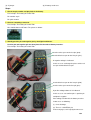
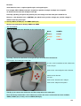
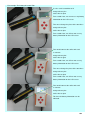
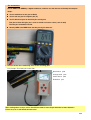
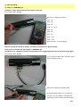
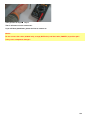
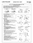
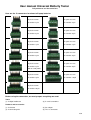
User manual Universal Batterty Tester
Tell you how to use the connectors
Here are the 13 connectors for almost all laptop batteries
Pin pitch: 2.0 mm
Pin pitch: 2.5 mm
Pin number: 5 pin
Pin number: 5 pin
Pin pitch: 2.0 mm
Pin pitch: 2.5 mm
Pin number: 6 pin
Pin number: 6 pin
Pin pitch: 2.0 mm
Pin pitch: 2.5 mm
Pin number: 7 pin
Pin number: 7 pin
Pin pitch: 2.0 mm
Pin pitch: 2.5 mm
Pin number: 8 pin
Pin number: 8 pin
Pin pitch: 2.0 mm
Pin pitch: 2.5 mm
Pin number: 8 pin
Pin number: 9 pin
(With an error proof)
Pin pitch: 2.0 mm
Pin pitch: 2.5 mm
Pin number: 9 pin
Pin number: 10 pin
Pin pitch: 2.0 mm
Pin number: 10 pin
Before using the connectors, we must prepare everything we need:
Tools:
(1). A digital multimeter
(2). A small screwdriver
Products and accessories:
(1). A detector
(2). An adapter
(3). A connecting wire
(4). The 13 connectors
1/7
(5). A jumper
(6). A battery under test
Steps:
1 Check the pin number and pin pitch of the battery.
For example: The battery of Lenovo T60
Pin number: 8 pin
Pin pitch: 2.0mm
2 Choose a matching connector.
For example: The battery of Lenovo T60
We should choose # RF-20-8. The picture as below:
3 Identify positive pin and negative pin by the digital multimeter.
Positive pin and negative pin are often placed in the ends of battery interface.
For example: The battery of Lenovo T60
Set the red test pen on the last pin (pin8).
Set the black test pen on the first pin (pin1).
A negative voltage is indicated.
In this case, we exchange the places of the red
test pen and the black test pen.
Set the black test pen on the last pin (pin8).
Set the red test pen on the first pin (pin1).
A positive voltage above 5V is indicated.
In this case, we can confirm pin1 is positive pin
and pin8 is negative.
If the voltage is below 5V, the battery must be
in two cases as following:
(1). Over discharge
(2). There is a CONTROL pin
In the next pages, we'll sepcify the two cases.
2/7
Remarks:
Some batteries have a couple of positive pins and negative pins..
For example, DELL WU946, both pin1 and pin2 are positive, both pin 8 and pin 9 are negative.
So we'd better measure the voltage of each pin.
Generally speaking, except for the positive pins, the voltage of all the other pins should be 0V.
However, a few batteries have a CONTROL pin, which have a positive voltage, too, and the voltage is
different from the postive pin.
4 Identify SMBC (CLOCK pin) and SMBD (DATA pin)
We have two methods to identify SMBC and SMBD
The 1st method:
First, we should know the definition of the connecting wire.
Black:
POWER-
Coffee:
CLOCK
Orange:
DATA
Red:
POWER+
Secondly, connect the balck wire to the positive pin and switch on the detector.
For example: The battery of Lenovo T60
Use the small screwdriver to fix the black wire
on the first pin.
Connect the connecting wire to the detector.
Switch on the detector.
It means:
Connect the detector to the adapter
Connect the adapter to AC power
Thirdly, try to connect the coffee wire and the orange wire to the other pins.
Once the battery information can be indicated, it means the correct connection has been available.
SMBC (CLOCK pin) is always next to SMBD (DATA pin).
3/7
For example: The battery of Lenovo T60
Use the small screwdriver to fix
orange wire on pin7
coffee wire on pin6
Few seconds later, we can not see any battery
information on the LCD screen.
Then we exchange the place of the two wires:
orange wire on pin6
coffee wire on pin7
Few seconds later, we still can not see any
battery information on the LCD screen.
Then we disconnect the coffee wire and
re-connect:
orange wire on pin6
coffee wire on pin5
Few seconds later, we still can not see any
battery information on the LCD screen.
Then we exchange the place of the two wires:
orange wire on pin5
coffee wire on pin6
Few seconds later, we still can not see any
battery information on the LCD screen.
Then we disconnect the coffee wire and
re-connect:
orange wire on pin5
coffee wire on pin4
This time the battery information can be
indicated.
4/7
The 2nd method:
Check SMBC and SMBD by a digital multimeter, and then use the detector to identify the two pins.
Steps:
① Set the multimeter at the gear of diode
② Set the red test pen on negative pin (P-)
③ Set the balck test pen on the other pins one by one
Two pins of them will give you a same or similar resistance value (>500 & <900)
The two pins should be D and C.
④ Identify SMBC and SMBD from the two pins by the detector.
5 Connect all the four conducting wires to the matching pins.
For example: The battery of Lenovo T60
→ pin8
Orange wire → pin5
Coffee wire → pin4
Red wire → pin1
Black wire
After reading above 5 steps, users should know how to learn the pin definition of most batteries.
For the rest, let us talk about the two cases:
5/7
(1). Over discharge
(2). There is a CONTROL pin
Go back to step 3 and we measure the voltage of each pin.
For example: DELL WU946
Measure the voltage of each pin.
Pin1 - 0V
Pin2 - 0V
Pin3 - 0V
Pin4 - 0.1 ~ 0.3V
Pin5 - 0V
Pin6 - 0V
Pin7 - 0V
Pin8 - 2.2V
Pin9 - 2.2V
Notice pin4 has a special voltage.
After measuring the voltage of all pins, we find one of them have a special voltage .
In this case, we confirm the special pin is a CONTROL pin.
And then we use a jumper to connect the special pin to the negative pin and measure the positive pin again.
For example: DELL WU946
Use a jumper to connect the special pin (pin4)
to the negative pin (pin1).
Measure the positive pin (pin9) again.
A normal voltage (above 5 V) is indicated.
If at this case, the voltage is still below 5V,
the battery must have been over discharged.
6/7
Then go back to step 4
→ step 5.
That is all how to use the connectors.
If you still have promblems, please feel free to contact us.
Notice:
Do not connect the coffee (CLOCK wire), orange (DATA wire) and black wire (POWER-) to positive pin!!
It may cause component damage!!
7/7