1
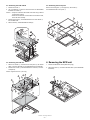
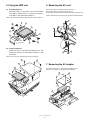
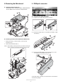
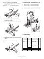
q INSTALLATION MANUAL CODE : 00ZUPX500VIME POS TERMINAL MODEL UP-X500 (V version) CONTENTS 1. Removing the rear cover unit . . . . . . . . . . . . . . . . . . . . . . . . . . . . . . . . . . 1 2. Removing the side cover . . . . . . . . . . . . . . . . . . . . . . . . . . . . . . . . . . . . . 1 3. Removing the LCD unit . . . . . . . . . . . . . . . . . . . . . . . . . . . . . . . . . . . . . . 1 4. Removing the MCR unit . . . . . . . . . . . . . . . . . . . . . . . . . . . . . . . . . . . . . . 2 5. Fixing the HDD unit . . . . . . . . . . . . . . . . . . . . . . . . . . . . . . . . . . . . . . . . . 2 6. Removing the AC cord . . . . . . . . . . . . . . . . . . . . . . . . . . . . . . . . . . . . . . . 3 7. Removing the AC adapter . . . . . . . . . . . . . . . . . . . . . . . . . . . . . . . . . . . . 3 8. Removing the Main board (Extention RAM module) . . . . . . . . . . . . . . . . 3 9. COM port connector. . . . . . . . . . . . . . . . . . . . . . . . . . . . . . . . . . . . . . . . . 4 9-1. FIXING THE REAR DISPLAY UP-I20DP. . . . . . . . . . . . . . . . . . . . . . . . . . . 4 9-2. FIXING THE POLE DISPLAY: UP-P20DP/DPB . . . . . . . . . . . . . . . . . . . . . 4 9-3. FIXING THE DRAWER UNIT: ER-03DW/04DW . . . . . . . . . . . . . . . . . . . . . 4 9-4. FIXING THE LAN CABLE . . . . . . . . . . . . . . . . . . . . . . . . . . . . . . . . . . . 4 10. Removing the contactless clerk key. . . . . . . . . . . . . . . . . . . . . . . . . . . . . 5 11. Specification. . . . . . . . . . . . . . . . . . . . . . . . . . . . . . . . . . . . . . . . . . . . . . . 5 Parts marked with "!" are important for maintaining the safety of the set. Be sure to replace these parts with specified ones for maintaining the safety and performance of the set. SHARP CORPORATION This document has been published to be used for after sales service only. The contents are subject to change without notice. CONSUMPTION • LCD (Back light) 15,000 h • MCR unit 300,000 pass BATTERY DISPOSAL Contains Lithium Battery. Must be Disposed of Properly. Contact Local Environmental Officials for Disposal Instructions. CAUTION RISK OF EXPLOSION IF BATTERY IS REPLACED BY AN INCORRECT TYPE. DISPOSE OF USED BATTERIES ACCORDING TO THE INSTRUCTIONS. AVOID: SHORT-CIRCUITING THE BATTERY TERMINALS. KEEP THE BATTERY AWAY FROM FIRE. * WHEN DISPOSING THE BATTERY, FOLLOW THE LOCAL RULES AND REGULATIONS. “BATTERY DISPOSAL” THIS PRODUCT CONTAINS LITHIUM BATTERY. THIS BATTERY MUST BE DISPOSED OF PROPERLY. REMOVE THE BATTERY FROM THE PRODUCT AND CONTACT FEDERAL OR STATE ENVIRONMENTAL AGENCIES FOR INFORMATION ON RECYCLING AND DISPOSAL OPTIONS. “TRAITEMENT DES ACCUMULATEUR USAGÉS” CE PRODUIT CONTIENT UN ACCUMULATEUR À LITHIUM. CET ACCUMULATEUR USAGÉ DOIT ÊTRE TRAITÉ CORRECTEMENT. ENLEVEZ L’ ACCUMULATEUR DU PRODUIT ET PRENEZ CONTACT AVEC VOTRE AGENCE ENVIRONNEMENTALE LOCALE POUR DES INFORMATIONS SUR LES MÉTHODES DE RECYCLAGE ET DE TRAITEMENT. UP-X500VI 3. Removing the LCD unit Precautions • Before installation, be sure to turn off the power. 3-1. Removing the top cover section Remove each screw 1, and lift the rear side of the top cover section 3 and disconnect each connector 2 and remove. • Use gloves to protect your hands from being cut by the angle and the chassis. • Connect all the cables securely. When connecting or disconnecting the cables, be careful not to apply stress to the cables. (It may cause disconnection.) • Ground the human body to prevent against troubles and dust adhesion to the LCD by static electricity. When assembling the LCD, use a discharge blower to prevent against dust intrusion. • Be careful of the high voltage of the inverter PWB transformer. • Place the top cabinet with LCD panel side down, Please use a clean dust free clothe to protect the touch panel and LCD area. 3 2 1. Removing the rear cover unit 1 Remove the screw 1, and remove the rear cover unit 2. 2 1 1 1 1 1 3-2. Removing the Top cover unit Caution: Top cover unit 7 is pushed down. 2 1. Remove the screw 1, and remove the wire holder 2. [Screw 1 is Black.] 2. Remove the screw 3, and remove the wire holder 4. 3. Remove the core 5 of the T/P cable. 4. Remove four screws 6, and disassemble the top cover unit 7. 2. Removing the side cover 5 1 3 2 Slide the lever 1 to release the lock. Slide the side cover 2 toward you and rotate and remove it. 4 6 7 6 2 1 UP-X500I Removing the rear cover unit –1– 3-3. Removing the LCD cabinet 3-5. Removing the touch panel 1. Remove the screw 1. Remove the T/P angle A 2, T/P angle B 3, with screws 1. And disassemble the Touch panel 2. 2. Use a screwdriver to catch the notched section and disassemble the MCR rear cabinet 2. Caution: • Wrap the screwdriver with waste cloth when using it without scratching the cabinet. • Rotate it in the direction of A and slide it in the direction of B, and it will come off easily. 4 3. Remove two screws 3, and disassemble the LCD rear cabinet 4 from the MCR side. 1 1 1 4. Remove screw 5, and disassemble the Clamp 6. 1 2 3 1 1 Cloth 3 1 3 4 3 1 2 2 A 1 5 6 B 3-4. Removing the LCD unit 4. Removing the MCR unit 1. Remove six screws 1, and remove the touch panel 2, the inserter cable 3, and the LED cable 4, and disassemble the LCD assembly. 1. Remove the MCR rear cabinet (Reference [3-3]). 2. Remove the screw 1, and remove the MCR cable 2 and disassemble the MCR 3. 2. Remove four screws 5, and disassemble the LCD unit 7 from the LCD plate 6. Caution: Tighten the screw 1 at 3.5kg. 5 1 1 1 6 5 1 1 3 3 1 1 4 5 2 5 7 UP-X500I Removing the MCR unit –2– 2 5. Fixing the HDD unit 6. Removing the AC cord 5-1. Assembly HDD unit Attach the holder 1 to the angle 2, and fix the assembly to the HDD 5 with the screw 3. Connect the connector 4 to the HDD 5. (Be careful of the direction.) Remove the screw 1, and remove the AC cord cover 2. Remove the screws 3, and remove the AC cover 4. Disconnect the connector and remove the earth cable 5 and the AC cord. Caution: Disconnect the power plug from the power outlet before work. Caution: All the parts are packed together with the set as accessories. 3 3 1 2 4 5 5 2 3 3 4 1 Pin 3 Red Line 1 5-2. Fixing the HDD unit Remove the screw 1 and remove the HDD cover 2. Disconnect the connector 5 and install the HDD unit 3 with the screw 4. 1 2 Caution: The screw 4 is packed with the set as an accessory. 1 1 2 7. Removing the AC adapter 4 Disconnect each screw 1, and remove the adapter cover 2. Remove each cabled 3, and remove the AC adapter 4. 1 3 1 5 2 4 3 3 UP-X500I Fixing the HDD unit –3– 8. Removing the Main board 9. COM port connector 8-1. Removing the AC adapter unit Remove the screw 1 and each cable 2. Slide and remove the AC adapter unit 3 as shown in the figure below. 1 2 3 9-1. Fixing the rear display (UP-I20DP) 9-1-1. Replace the UP-I20DP sheet metal with a new one. 2 9-1-2. Remove the display sheet 1 and install the UP-I20DP 3 with the screw 2. 1 8-2. Removing the main board unit (Extention RAM module) 1. Remove each screw 1 and each cable 2, and remove the main board unit 3. 2. Remove Extention RAM module 4. 2 Caution: When installing or removing the memory, be careful not to bring the memory module into contact with the CPU angle and the CPU fan. 3 2 9-1-3. Wind the UP-I20DP harness one turn around the rib 1, insert the connector 2 and install the rear cover unit. 1 1 1 4 1 2 1 1 3 2 2 From 2004 February production, the sheet metal for the UP-X500 is included in the package. UP-X500I Removing the Main board –4– 10. Removing the contactless clerk key 9-2. Fixing the pole display (UP-P20DP/DPB) Fix the cable clamp 2 with the screw 1, and attach the UP-P20DP cable 3. Caution: Parts 1, 2, 4, 5 are packed together with the set. 1 1. Remove the screw 1, and remove the wire holder 2. 2. Remove the screw 3, and remove the wire holder 4. 3. Remove two screws 5, and disassemble the hinge angle 6. 4. Fixing the contactless clerk key unit 8, with the screw 7. 2 1 3 2 3 4 5 4 5 5 6 7 9-3. Fixing the drawer unit (ER-03DW/04DW/05DW) Fix the cable clamp 2 and earth wire 3 with the screw 1, and attach the drawer cable 4. 8 Caution: Parts 1, 2 are packed together with the drawer as accessories. 1 2 3 4 11. Specification 9-4. Fixing the LAN cable Fix each cable 2 with each screw 1, and connect the LAN cable 3. Options <UP-X500V> Caution: Parts 2, 3 are packed together with the set. Item Model Name Customer Display UP-I20DP 2 line 20 digits dot display Mounted in the cabinet Customer Pole display UP-P20DP 2 line 20 digits dot display External pole display UP-P20DPB Specification Remote Drawer ER-03DW ER-04DW ER-05DW 1 2 Receipt & Journal Printer ER-01PU Hand Scanner ER-A6HS1 for reading barcode Contactless clerk key UP-R10CL 10 keys set 3 UP-X500I Removing the contactless clerk key –5– ER-01PUG 2 station (Receipt/Journal) printer Note q COPYRIGHT 2004 BY SHARP CORPORATION All rights reserved. Printed in Japan. No part of this publication may be reproduced, stored in a retrieval system, or transmitted. In any form or by any means, electronic, mechanical, photocopying, recording, or otherwise, without prior written permission of the publisher. SHARP CORPORATION Digital Document Systems Group Products Quality Assurance Department Yamatokoriyama, Nara 639-1186, Japan 2004 January Printed in Japan t