1
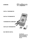
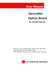
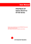
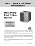
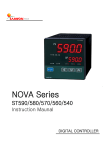
User Manual
RS485 Option Board
for SV-iS5/iH Series
Read this manual carefully before using the RS485 OPTION BOARD
and follow the instructions exactly.
After reading this manual, keep it at handy for future reference.
LG Industrial Systems
Thank you for purchase of LG RS 485 Option Board!
SAFETY PRECAUTIONS
Always follow safety precautions to prevent accidents and potential hazards from occurring.
Safety precautions are classified into “WARNING” and “CAUTION” in this manual.
WARNING
CAUTION
Indicates a potentially hazardous situation which, if not avoided,
can result in serious injury or death.
Indicates a potentially hazardous situation which, if not avoided,
can result in minor to moderate injury, or serious damage to the
product.
Throughout this manual we use the following two illustrations to make you aware of safety
considerations:
Identifies potential hazards.
Read the message and follow the instructions carefully.
Identifies shock hazards.
Particular attention should be directed because dangerous voltage may be present.
Keep this manual at handy for quick reference.
CAUTION
Do not touch the CMOS components unless the board is grounded.
ESD can cause break down of CMOS components.
Do not change the communication cable with the inverter power is applied.
Otherwise, there is a danger of connecting error and damage to the board.
Make sure to precisely insert the connector of inverter and option board
Otherwise, there is a danger of connecting error and damage to the board.
Check the parameter unit when setting the parameters.
Otherwise, there is a danger of connecting error and damage to the board.
1.
INTRODUCTION
By using a RS 485 OPTION BOARD, SV-iS5/iH inverter can be connected to a RS 485 network.
1.1.
When you use the RS 485 Option Card …
Inverter can be controlled and monitored by the sequence program of the PLC or other master module.
Up to 31 drives or other slave devices may be connected in a multi-drop fashion on the RS485 network and may be monitored or controlled by a single PLC or PC. Parameter setting and change
are available through PC.
1.1.1.
Interface type of RS485 reference
- Allows the drive to communicate with any other computers.
- Allows connection of up to 31 drives with multi-drop link system.
- Noise-resistant interface
Users can use any kind of RS232-485 converters. The specifications of converters depend on the
manufacturers. Refer to the converter manual for detailed specifications.
1.1.2.
Before Installation
Before installation and operation, this manual should be read thoroughly. If not, it can cause personal injury
or damage other equipment.
2.
SPECIFICATION
2.1.
Performance specification
Items
Specifications
Communication method
RS485 (Using RS232-485 Converter)
Transmission form
Bus method, Multi-drop Link System
Applicable inverter
IS5/iH series drive
Number of drives
Maximum 31 drives connectable
Transmission distance
Max. 1200m (Less than 700 m recommended)
Converter
RS232-485, Use PC with RS232 card embedded
2.2.
Hardware Specifications
Items
Installation
Power
Supply
Specifications
Option connector on the inverter control board
Control B/D
Comm. B/D
5V dc supplied from inverter power supply
Power supplied using 5V DC-DC converter on option
board
1
2.3.
3.
3.1.
Communication Specification
Items
Specifications
Communication speed
1200 /2400/4800/9600/19200 bps Selectable
Control procedure
Asynchronous communication system
Communication system
Half duplex system
Character system
BINARY (8 bit)
Stop bit
1 bit
Error check (CRC16)
2 byte
Parity check
None
PRODUCT DETAIL
Layout and detail
Name
Description
Connector
Connector to inverter main PCB
P
485 signal - high
Signal
Communication
N
485 signal – low
connection
signal connection
G
485 Ground
terminal
terminal
S
Shield
T1, T2
Connect a terminating resistor
Figure 1-1. Installating RS485 Option Card to SV-iS5
2
U4
U1
CNC3
G5
BC5
U4
BC4
B7
CNC7
X1
U3
ERR RX
TX
CPU
CN1
Connect CN1to CNC7
U7
R
U6
iH
U8
6
iH Control Board
RS485 Board
S GT2T1N P
ㅊ
Figure 1-2. Installating RS485 Option Card to SV-iH
3.2.
Status LED
CPU LED
Normal operation of the board
RXD LED
Receiving 485 signal
TXD LED
Responding to 485 signal
ERR LED
Intermittent blinking
Wrong data received (normal)
Blingking with CPU LED
DPRAM Communication Error
coincidentally
Blinking after CPU LED blinks
Network Connection TimeOut
3
4.
INSTALLATION
4.1.
Option board installation guide
1. Remove the keypad on the inverter and connect the RS485 option board (See the Figure 1).
2. Double check the board is firmly installed to the board and then apply the inverter power.
3. When power ON, CPU LED is blinking per second after all LEDs blink one after another.
4. If “CPU LED” is not blinking, turn off the inverter power swiftly (if not, inverter and the board may get
damaged.) and check for the proper installation of the board. If the problem persists, contact LG
distributor.
5. Check I/O 47 is set to “RS485”.
6. When the above condition is met, set the communication parameters as shown below.
[For SV-iS5]
Parameter code
Display
Setting Value
< COM-01 >
Opt B/D
RS485 displayed automatically
< COM-02 >
Opt mode
Setting command to be controlled by option
< I/O- 46 >
Inv. number
< I/O- 47 >
Baud-rate
9600 bps (Factory default)
< I/O- 48 >
Lost command (Note 1)
User defined
< I/O- 49>
Time.Out (Note 1)
0.1 sec (Factory default)
1~31
(Verify the assigned number is not duplicated.)
Note1) set for emergency stop of the inverter when inverter and master communication becomes
faulty. Activates when communcation has not been made during setting time. This means remote
controlling of inverter has not executed. Set these for safe use of the inverter.
[For SV-iH]
Parameter code
Display
Setting Value
< FUN-01 >
Freq. set
“Remote”
< FUN-02 >
Run/stop set
“Remote“
< I/O- 50 >
Inv. number
< I/O- 51 >
Baud-rate
9600 bps (Factory default)
< I/O- 52 >
Comm.timeout(Note1)
10.0 (Factory default)
1~31
(Verify the assigned number is not duplicated.)
Note1) set for emergency stop of the inverter when inverter and master communication becomes
faulty. Activates when communcation has not been made during setting time. This means remote
controlling of inverter has not executed. Set these for safe use of the inverter.
If Comm. Timeout is set to “0”, inverter maintains its status without stopping at the event of
network communication disconnection.
7. Turn off the inverter power to connect the converter when step 6 is finished.
8. Connect the terminating resistor at the end of network (See the figure 3).
4
4.2.
RS232-485 converter installation
See the converter manual for accurate installation.
4.3.
Computer, Converter and RS485 Option Card Configuration
4.3.1.
System configuration
Maximum cable length is 1200m but recommended length is within 700.
The number of connectable inverter is 31.
Computer
232/485
Converter
Option card
Option card
Inverter 1
…
Inverter 2
Option card
Inverter n
Figure 2. System configuration
4.3.2.
Communication signal connection
S GND T2
T1
N
P
Figure 3. Option card terminal layout
Pin
Description
S
GND
Shield
Ground
T1
T2
Termination
* S: Networkd line ground shoud be done only one point.
Connect it to screw near terminal shield when grounding through inverter.
* GND: Ground terminal for 485 communication
* T1, T2: Shorting these terminals connects a terminating resistor.
5
N
P
Signal
5.
COMMUNICATION PROTOCOL
Use LG RS485 protocol (Open protocol). Contact LG representatives.
Computer or other hosts can be Master and inverters Slave. Inverter responds to Read/Write
command from Master.
5.1.
Supported command codes
Function Code
Name
‘R’
Parameter Read
‘W’
Parameter Write
‘X’
Monitor Register
‘Y’
Monitor Execution
(Important: Use ASCII CODE (Capital Letter).)
5.2.
BroadCast Function
Use it to send command to all inverters at the network.
All inverters respond when command is sent from Station # 255.
5.3.
Error Code
Error Code
ILLEGAL
FUNCTION
ILLEGAL DATA
ADDRESS
ILLEGAL DATA
VALUE
WRITE MODE
ERROR
FRAME ERROR
TIME OUT
ERROR
DPRAM OFF LINE
INVALID ID
NUMBER
UNDEFINED
CONDITION
Display
IF
IA
ID
Description
Invalid command received.
Invalid parameter address received.
Monitor executed without resistoring monitor.
Invalid data received.
WM
Read Only or not-programmable during run.
FE
Frame size, internal Num or Sum is different.
TO
DPRAM communication failed for the set time.
DO
DPRAM is Off-line.
IN
Different address received.
UC
Undefined condition received.
6
6.
TROUBLESHOOTING
Refer to this section when communication error occurs.
CPU LED does not work properly.
Inverter doesn’t work properly or connection between options of VFD is
Symptom
not achieved correctly.
1. Check power source of Inverter.
Solution
2. Check connection status whether option card is correctly inserted into
the slot of inverter or not, if inverter works normally.
TXD LED and RXD LED do not work properly.
What to check
Corrective action
Is the power provided to the converter?
Provide electric power to the converter.
Are the connections between converter and
Refer to converter manual.
computer correct?
Is communication card installed into the
Install it correctly referring to
inverter correctly?
“4.Installation”
Is communication program running on the
Start communication program.
computer?
Is baud rate of computer and inverter correctly
Set baud rate identically referring to “4.
set?
Installation”
Is the format of user program* right?
Correct user program.
Is the connection between converter and
Connect correctly referring to “4.
communication card right?
Installation”
* User program is User-made S/W for PC.
ERR LED is blinking.
Status
Blinking intermittently
Solution
Normal operation. Wrong data is received due to noise and
other causes.
Blinking after CPU LED
Network communication is not made for TimeOut (I/O 49).
blinks
Check Master status.
Blinking with CPU LED at the
same time
Communication error between inverter and option card.
Cycle the inverter power (On/Off). If this problem persists,
contact LG representatives.
* Refer to COM group parameters for Freq/Run/Stop command setting.
7
7.
PARAMETER CODE (HEX)
<Common>: Area accessible regardless of inverter models (Note 2)
Parameter
Address
0000
Parameter Name
Unit
Read/Write
Inverter model
-
R
Data Value (Hex)
4: SV-iS5 3:SV-IH
SV-iS5
0: 0.75 1:1.5 2:2.2 3: 3.7 4: 5.5
5: 7.5
6: 11 7: 15 8: 18.5 9: 22
A: 30
B:37 C:45 D: 55 E: 75 F: 90
10: 110 11: 132 12: 160 13: 200 14: 220
0001
Inverter capacity
-
R
15: 280 16:375
(Unit: kW)
SV-IH
A: 30 B: 37 C: 45 D: 55 E: 75 F: 90
10: 110 11: 132 12: 160 14: 220
(Unit: kW)
0002
Inverter Input Voltage
-
R
0: 220V 1: 440V
SV-iS5
0100: Ver. 1.00, 0101: Ver 1.01
0003
S/W Version
-
R
SV-iH
0200 : Ver. 2.00, 0201: Ver. 2.01
0004
Parameter Lock
-
R/W
0005
Frequency Reference
0.01Hz
R/W
0: Lock (default)
1: Unlock
0-60000
Bit 0: Stop
Bit 1: Forward Run
0006
Run Command
-
R/W
Bit 2: Reverse Run
Bit 3: Fault Reset
Bit 4: Emergency Stop
(Bit 0 also resets fault)
0007
Acceleration Time
0.1 sec
R/W
0008
Deceleration Time
0.1 sec
R/W
0009
Output Current
0.1 A
R
000A
Output Frequency
0.01 Hz
R
000B
Output Voltage
0.1 V
R
000C
DC Link Voltage
0.1 V
R
000D
Output Power
0.1 kW
R
8
Parameter
Address
Parameter Name
Unit
Read/Write
Data Value (Hex)
SV-iS5
Bit 0: Stop, Bit 1: Forward Running
Bit 2: Reverse Running Bit 3:Fault (Trip)
Bit 4: Accelerating Bit 5: Decelerating
Bit 6: Output Frequency Arrival
Bit 7:DC Braking, Bit 8: Stopping
Bit 9: Not used
Bit10: BrakeOpen
Bit 11: FWD Run Command ON,
Bit 12: REV Run command ON,
Bit13: Rem. Run/Stop
Bit14: Rem. Freq. Cmd
000E
Sequence Monitor
-
R
SV-iH
BIT 0 : Stop
BIT 1 : Forward Run
BIT 2 : Reverse Run
BIT 3 : Fault (Trip)
BIT 4 : Accelerating
BIT 5 : Decelerating
BIT 6 : Output Frequency Arrival
BIT 7 : DC Braking
BIT 8 : Stopping
BIT13: Rem. Run/Stop
BIT 14: Rem. Freq. Cmd
SV-iS5
Bit 0:OCT1,Bit 1: OV, Bit 2: EXT-A
Bit 3: BX, Bit 4:OCT2, Bit 5: GF,
Bit 6: OH,Bit 7: ETH, Bit 8: OLT, Bit 9:
HW-diag,Bit10:EXT-B,Bit11:FO
000F
Trip information
-
R
Bit12:OPT,Bit13:POBit,14:IOLT, Bit15:LV
SV-iH
Bit 0: OC Bit 1: OV Bit 2:EXT
Bit 3: BX Bit 4:LV Bit 5:FUSE OPEN Bit 6:
GF Bit 7: OH
Bit 8: ETH Bit 9:OLT Bit 10: MCF
Bit 12: SCT Bit 15: IOLT
9
Parameter
Address
Parameter Name
Unit
Read/Write
Data Value (Hex)
SV-iS5
Bit 0: P1, Bit 1: P2, Bit 2: P3
Bit 3: P4, Bit 4: P5, Bit 5: P6,
Bit 6: RST, Bit 7: BX, Bit 8: JOG, Bit 9:
0010
Input Terminal Status
-
R
FX, Bit 10: RX
SV-iH
Bit 0: FX Bit 1:RX Bit 2:BX
Bit 3: RST Bit 8: P1 Bit 9: P2
Bit 10: P3 Bit 11: P4
Bit 12: P5 Bit 13: P6
Bit 0: Q1 (OC1) , Bit 1: Q2 (OC2)
Bit 2: Q3 (OC3)
SV-iS5
0011
Output Terminal Status
-
R
Bit 3: AUX Bit 4: 30AC
SV-iH
Bit 3: AUX1 Bit 4: AUX2
x0012
V1
-
R
0x0013
V2
-
R
0x0014
I
-
R
0x0015
RPM
-
R
SV-iS5 0 – FFC0
SV-iH 0-FFFF
SV-iS5 0 – FFC0
SV-iH 0-FFFF
SV-iS5 0 – FFC0
SV-iH 0- FFFF
(Note 2) The changed value in Common affects the current setting but returns to the previous setting when power is
cycled or Inverter is reset. However, changing value is immediately reflected in other parameter groups even in the case
of Reset or Power On/Off.
10
SV-iS5
< DRV group >
Addr
NO.
Description
Default
Maximum
Minimum
Unit
5100
DRV#00
Cmd. freq
0
MaxFreq
0
0.01Hz
5101
DRV#01
Acc. Time
100
6000
0
0.1sec
5102
DRV#02
Dec. Time
200
6000
0
0.1sec
5103
DRV#03
Drive mode
1
2
0
5104
DRV#04
Freq. mode
0
4
0
5105
DRV#05
Step freq - 1
1000
MaxFreq
startFreq
0.01Hz
5106
DRV#06
Step freq - 2
2000
MaxFreq
startFreq
0.01Hz
5107
DRV#07
Step freq - 3
3000
MaxFreq
startFreq
0.01Hz
5108
DRV#08
Current
-
-
-
0.1A
5109
DRV#09
Speed
-
-
-
1rpm
510A
DRV#10
DC Link Voltage
-
-
V
Unit
ess
< FU1 group >
Addr
NO.
Description
Default
Maximum
Minimum
5203
FU1 #03
Run prohibit
0
2
0
5205
FU1 #05
Acc. pattern
0
4
0
5206
FU1 #06
Dec. pattern
0
4
0
5207
FU1 #07
Stop mode
0
2
0
5208
FU1 #08
DcBr freq.
500
6000
startFreq
0.01Hz
5209
FU1 #09
DcBlk time
10
6000
0
0.01sec
520A
FU1 #10
DcBr value
50
200
0
%
520B
FU1 #11
DcBr time
10
600
0
0.1sec
520C
FU1 #12
DcSt value
50
200
0
%
520D
FU1 #13
DcSt time
0
600
0
0.1sec
5214
FU1 #20
Max freq.
6000
40000
4000
0.01Hz
5215
FU1 #21
Base freq.
6000
maxFreq
3000
0.01Hz
5216
FU1 #22
Start freq.
50
6000
1
0.01Hz
5217
FU1 #23
Freq limit
0
1
0
5218
FU1 #24
F-limit Lo.
50
highFreq
startFreq
0.01Hz
5219
FU1 #25
F-limit Hi.
6000
maxFreq
lowFreq
0.01Hz
521A
FU1 #26
Torque boost
0
1
0
521B
FU1 #27
Fwd boost
20
150
0
0.1%
521C
FU1 #28
Rev boost
20
150
0
0.1%
521D
FU1 #29
V/F pattern
0
2
0
521E
FU1 #30
User freq. 1
1500
maxFreq
0
ess
11
0.01Hz
Addr
NO.
Description
Default
Maximum
Minimum
Unit
521F
FU1 #31
User volt. 1
25
100
0
%
5220
FU1 #32
User freq. 2
3000
maxFreq
0
0.01Hz
5221
FU1 #33
User volt. 2
50
100
0
%
5222
FU1 #34
User freq. 3
4500
maxFreq
0
0.01Hz
5223
FU1 #35
User volt. 3
75
100
0
%
5224
FU1 #36
User freq. 4
6000
maxFreq
0
0.01Hz
5225
FU1 #37
User volt. 4
100
100
0
%
5226
FU1 #38
Volt control
1000
1100
400
0.1%
5227
FU1 #39
Energy save
0
30
0
%
5232
FU1 #50
ETH select
0
1
0
5233
FU1 #51
ETH 1min
180
200
ETH Cont
%
5234
FU1 #52
ETH Cont
100
150
50
%
5235
FU1 #53
Motor type
0
1
0
5236
FU1 #54
OL level
150
150
30
%
5237
FU1 #55
OL time
100
300
0
0.1sec
5238
FU1 #56
OLT select
1
1
0
5239
FU1 #57
OLT level
180
200
30
%
523A
FU1 #58
OLT time
600
600
0
0.1sec
523B
FU1 #59
Stall prev.
0
7
0
523C
FU1 #60
Stall level
180
250
30
%
NO.
Description
Default
Maximum
Minimum
Unit
5307
FU2 #07
Dwell freq
500
maxFreq
StartFreq
0.01Hz
5308
FU1 #08
Dwell time
0
100
0
0.1sec
530A
FU2 #10
Jump freq
0
1
0
530B
FU2 #11
jump lo 1
1000
jump Hi [0]
StartFreq
0.01Hz
530C
FU2#12
jump Hi 1
1500
maxFreq
jump Lo[0]
0.01Hz
530D
FU2 #13
jump lo 2
2000
jump Hi [1]
StartFreq
0.01Hz
530E
FU2 #14
jump Hi 2
2500
maxFreq
jump Lo[1]
0.01Hz
530F
FU2 #15
jump lo 3
3000
jump Hi [2]
StartFreq
0.01Hz
5310
FU2 #16
jump Hi 3
3500
maxFreq
jump Lo[2]
0.01Hz
5311
FU2 #17
Start Curve
40
100
1
%
5312
FU2 #18
End Curve
40
100
1
%
5313
FU2 #19
Trip select
0
3
0
BIT
5314
FU2 #20
Power-on run
0
1
0
ess
< FU2 group >
Addr
ess
12
Addr
NO.
Description
Default
Maximum
Minimum
5315
FU2 #21
RST restart
0
1
0
5316
FU2 #22
Speed Search
0
15
0
5317
FU2 #23
SS Sup-Curr
100
200
80
5318
FU2 #24
SS P-gain
100
9999
0
5319
FU2 #25
SS I-gain
1000
9999
0
531A
FU2 #26
Retry number
0
10
0
531B
FU2 #27
Retry delay
10
600
0
531E
FU2#30
Motor select
0
9
0
531F
FU2#31
Pole number
4
12
2
5320
FU2 #32
Rated-Slip
200
1000
0
0.01Hz
5321
FU2 #33
Rated-Curr
36
2000
10
0.1A
5322
FU2 #34
Noload-Curr
7
2000
5
0.1A
5324
FU2 #36
Efficiency
72
100
70
%
5325
FU2 #37
Inertia rate
0
1
0
5327
FU2 #39
Carrier freq
50
150
10
5328
FU2 #40
Control mode
0
2
0
5329
FU2 #41
Auto tuning
0
1
0
532A
FU2 #42
Rs (Note 4)
(Note 3)
5000
0
0.001ohm
532B
FU2 #43
Rr (Note 5)
(Note 3)
5000
0
0.001ohm
532C
FU2 #44
Lsigma (Note 6)
(Note 3)
MaxInduc
0
0.001mH
532D
FU2 #45
SL P-gain
32767
32767
0
532E
FU2 #46
SL I-gain
3276
32767
0
532F
FU2 #47
proc PI mode
0
1
0
5330
FU2 #48
PID Ref
1
1
0
5331
FU2 #49
PID Ref Mode
0
5
0
5332
FU2 #50
PID Out Dir
1
1
0
5333
FU2 #51
PID F/B
0
2
0
5334
FU2 #52
PID P-gain
3000
9999
0
0.1%
5335
FU2 #53
PID I-time
300
320
0
0.1sec
5336
FU2 #54
PID D-time
0
9999
0
0.1msec
5337
FU2 #55
PID +limit
6000
maxFreq
0
0.01Hz
5338
FU2 #56
PID -limit
6000
maxFreq
0
0.01Hz
5339
FU2 #57
PID Out Inv
0
1
0
533A
FU2 #58
PID OutScale
1000
9999
1
0.1%
533B
FU2 #59
PID P2-gian
1000
9999
0
0.1%
533C
FU2 #60
P-gain Scale
1000
1000
0
0.1%
5345
FU2 #69
Acc/Dec ch F
0
maxFreq
0
0.01Hz
ess
13
Unit
BIT
0.1sec
0.1kHZ
Addr
NO.
Description
Default
Maximum
Minimum
5346
FU2 #70
Acc/Dec freq
0
1
0
5347
FU2 #71
Time scale
1
2
0
5348
FU2 #72
PowerOn disp
0
12
0
5349
FU2 #73
User disp
0
2
0
534A
FU2 #74
RPM factor
100
1000
1
534B
FU2 #75
DB mode
1
2
0
534C
FU2 #76
DB %ED
10
30
0
534F
FU2 #79
S/W Debug02
0
1
0
5351
FU2 #81
2nd Acc time
50
6000
0
0.1sec
5352
FU2 #82
2nd Dec time
100
6000
0
0.1sec
5353
FU2 #83
2nd BaseFreq
6000
maxFreq
3000
0.01Hz
5354
FU2 #84
2nd V/F
0
2
0
5355
FU2 #85
2nd F-boost
20
150
0
0.1%
5356
FU2 #86
2nd R-boost
20
150
0
0.1%
5357
FU2 #87
2nd Stall
150
150
30
%
5358
FU2 #88
2nd ETH 1min
150
200
5359
FU2 #89
2nd ETH Cont.
100
535A
FU2 #90
2nd R-Curr
36
538D
FU2 #93
Para. Init
ess
2nd ETH
2nd ETH
Cont
Unit
%
%
%
50
%
2000
10
0.1A
0
8
0
1min
(Note 3,4,5,6) Value depends on motor capacity.
< I/O group >
Addr
NO.
Description
Default
Maximum
Minimum
Unit
5401
I/O #01
V1 filter
10
9999
0
ms
5402
I/O #02
V1 volt x1
0
V1 vort x2
0
0.01V
5403
I/O #03
V1 freq y1
0
maxFreq
0
0.01Hz
5404
I/O #04
V1 volt x2
1000
1000
V1 volt x1
0.01V
5405
I/O #05
V1 freq y2
6000
maxFreq
0
0.01Hz
5406
I/O #06
I filter
10
9999
0
ms
5407
I/O #07
I curr x1
400
I curr x2
0
0.01mA
5408
I/O #08
I freq y1
0
maxFreq
0
0.01Hz
5409
I/O #09
I curr x2
2000
2000
I curr x1
0.01mA
540A
I/O #10
I freq y2
6000
maxFreq
0
0.01Hz
ess
14
Addr
NO.
Description
Default
Maximum
Minimum
540B
I/O #11
Wire broken
0
2
0
540C
I/O #12
P1 define
0
32
0
540D
I/O #13
P2 define
1
32
0
540E
I/O #14
P3 define
2
32
0
5411
I/O #17
Ti Filt Num
15
50
2
5414
I/O #20
Jog freq
1000
MaxFreq
startFreq
0.01Hz
5415
I/O #21
Step freq - 4
4000
MaxFreq
startFreq
0.01Hz
5416
I/O #22
Step freq - 5
5000
MaxFreq
startFreq
0.01Hz
5417
I/O #23
Step freq - 6
4000
MaxFreq
startFreq
0.01Hz
5418
I/O #24
Step freq - 7
3000
MaxFreq
startFreq
0.01Hz
5419
I/O #25
Acc time– 1
200
6000
0
0.1sec
541A
I/O #26
Dec time – 1
200
6000
0
0.1sec
541B
I/O #27
Acc time – 2
300
6000
0
0.1sec
541C
I/O #28
Dec time – 2
300
6000
0
0.1sec
541D
I/O #29
Acc time – 3
400
6000
0
0.1sec
541E
I/O #30
Dec time - 3
400
6000
0
0.1sec
541F
I/O #31
Acc time – 4
500
6000
0
0.1sec
5420
I/O #32
Dec time – 4
500
6000
0
0.1sec
5421
I/O #33
Acc time – 5
400
6000
0
0.1sec
5422
I/O #34
Dec time – 5
400
6000
0
0.1sec
5423
I/O #35
Acc time – 6
300
6000
0
0.1sec
5424
I/O #36
Dec time – 6
300
6000
0
0.1sec
5425
I/O #37
Acc time – 7
200
6000
0
0.1sec
5426
I/O #38
Dec time – 7
200
6000
0
0.1sec
5428
I/O #40
FM mode
0
3
0
5429
I/O #41
FM adjust
100
200
10
%
542A
I/O #42
FDT freq
3000
maxFreq
0
0.01Hz
542B
I/O #43
FDT band
1000
maxFreq
0
0.01Hz
542C
I/O #44
Aux mode
12
23
0
542D
I/O #45
Relay mode
2
7
0
542E
I/O #46
Inv No.
1
31
1
542F
I/O #47
Baud rate
3
4
0
5430
I/O #48
Lost command
0
2
0
5431
I/O #49
Time out
10
1200
1
ess
Unit
BIT3
0.1sec
* Contact LG representatives if address for Auto sequence operation parameters is needed.
15
< EXT group >
Addr
NO.
Description
Default
Maximum
Minimum
5501
EXT #01
Sub B/D
5502
EXT #02
P4 define
3
32
0
5503
EXT #03
P5 define
4
32
0
5504
EXT #04
P6 define
5
32
0
5505
EXT #05
V2 mode
0
2
0
5506
EXT #06
V2 filter
10
9999
0
msec
5507
EXT #07
V2 volt x1
0
V2 volt x2
0
0.01V
5508
EXT #08
V2 freq y1
0
maxFreq
0
0.01Hz
5509
EXT #09
V2 volt x2
1000
1000
V2 volt x1
0.01V
550A
EXT #10
V2 freq y2
6000
maxFreq
0
0.01Hz
550E
EXT #14
F mode
0
2
0
550F
EXT #15
F pulse set
0
1
0
5510
EXT #16
F pulse num
1024
4096
360
5511
EXT #17
F filter
10
9999
0
msec
5512
EXT #18
F pulse x1
0
F pulse x2
0
0.1kHz
5512
EXT #18
F pulse x1
0
F pulse x2
0
0.1kHz
5513
EXT #19
F freq y1
0
maxFreq
0
0.01Hz
5514
EXT #20
F pulse x2
100
1000
F pulse x1
0.1kHz
5515
EXT #21
F freq y2
6000
maxFreq
0
0.01Hz
5516
EXT #22
PG P-gain
3000
9999
0
5517
EXT #23
PG I-gain
300
9999
0
5518
EXT #24
PG Slip Freq
100
200
0
551E
EXT #30
Q1 define
0
23
0
551F
EXT #31
Q2 define
1
23
0
5520
EXT #32
Q3 define
2
23
0
5522
EXT #34
LM mode
1
3
0
5523
EXT #35
LM adjust
100
200
10
5528
EXT #40
AM1 mode
0
3
0
5529
EXT #41
AM1 adjust
100
200
10
552A
EXT #42
AM2 mode
3
3
0
552B
553C
553D
EXT #43
EXT #60
EXT #61
AM2 adjust
SPD P-Gain
SPD I-Gain
100
10
10
200
500
500
10
1
1
553E
EXT #62
POS P-gain
10
500
1
553F
EXT #63
POS I-gain
10
500
1
5540
5541
5542
EXT #64
EXT #65
EXT #66
Slip limit
Oper mode
Enc 0pulse
500
1
1000
500
4
2000
0
0
1000
ess
16
Unit
%
%
%
%
0.01Hz
Addr
ess
5543
5544
5545
NO.
Description
Default
Maximum
Minimum
EXT #67
EXT #67
EXT #68
Enc 1pulse
ROT ratio
STBY ROT
1000
10
0
2000
100
1000
1000
1
0
5546
EXT #69
STBY SPD
0
4000
0
5547
EXT #70
10
100
1
5548
EXT #71
SPD sync
10
20
1
5549
EXT #72
POS offset
0
9999
0
554A
EXT #73
User dir
0
1
0
554B
EXT #74
Max speed
1800
9999
1000
554C
EXT #75
Motor pulse
1000
2000
500
554D
EXT #76
DAC0 set
12
99
10
554E
EXT #77
DAC1 set
24
99
10
555A
EXT #89
Station ID
1
63
0
POS Sync
Unit
< COM group >
Addr
NO.
Description
5601
COM #01
Opt B/D
5602
COM #02
5603
5604
5605
560A
560B
560C
560D
5611
5614
561E
561F
5620
5621
5622
5623
5624
5625
5626
5628
5629
562A
562B
562C
562D
562E
562F
5630
5634
COM
COM
COM
COM
COM
COM
COM
COM
COM
COM
COM
COM
COM
COM
COM
COM
COM
COM
COM
COM
COM
COM
COM
COM
COM
COM
COM
COM
ess
#03
#04
#05
#10
#11
#12
#13
#17
#20
#30
#31
#32
#33
#34
#35
#36
#37
#38
#40
#41
#42
#43
#44
#45
#46
#47
#48
#52
Default
Maximum
Minimum
Opt mode
0
3
0
Opt version
D-in mode
Digital Ftr
MAC ID
Baud rate
Out instance
In instance
Station ID
Profi MAC ID
Output Num
Output 1
Output 2
Output 3
Output 4
Output 5
Output 6
Output 7
Output 8
Input Num
Input 1
Input 2
Input 3
Input 4
Input 5
Input 6
Input 7
Input 8
Modbus Mode
1.00
0
15
63
0
0
0
1
1
3
10
14
15
0
0
0
0
0
2
5
6
0
0
0
0
0
0
0
6
50
63
2
3
3
63
127
8
22527
22527
22527
22527
22527
22527
22527
22527
8
22527
22527
22527
22527
22527
22527
22527
22527
0
0
2
0
0
0
0
0
1
0
0
0
0
0
0
0
0
0
0
0
0
0
0
0
0
0
0
0
17
Unit
* I/O-46, 47: station number and baud rate setting
COM-01 [Opt B/D]
Displays option board installed.
Automatically set when board is installed.
COM-02 [Opt Mode]
Run/Stop/Frequency Reference setting via Option Board
Value
Display
Description
0
None
1
Command
Run/Stop command via Option
2
Freq
Frequency command via Option
3
Cmd + Freq
Disabled
Run/Stop/Frequency command via Option
Use Common area #0x0005 for Frequency command via Option.
Use Common area #0x0006 for Run/Stop command via Option.
COM-03 [Opt Version]
Displays option card’s version.
< APP group >
Addr
NO.
Description
Default
Maximum
Minimum
5701
APP #01
APP mode
0
3
0
5702
APP #02
Trv. Amp[%]
0
200
0
0.1%
5703
APP #03
Trv. Scr
0
500
0
0.1%
5704
APP #04
Trv Acc Time
20
6000
1
0.1sec
5705
APP #05
Trv Dec Time
30
6000
1
0.1sec
5706
APP #06
Trv Off Hi
0
200
0
0.1%
5707
APP #07
Trv Off Lo
0
200
0
0.1%
5708
APP #08
Aux Mot Run
0
4
0
5709
APP #09
Starting Aux
1
4
1
570A
APP #10
Auto Op Time
0
5940
0
570B
APP #11
Start freq1
4999
maxFreq
0
0.01Hz
570C
APP #12
Start freq2
4999
maxFreq
0
0.01Hz
570D
APP #13
Start freq3
4999
maxFreq
0
0.01Hz
570E
APP #14
Start freq4
4999
maxFreq
0
0.01Hz
570F
APP #15
Stop freq1
1500
maxFreq
0
0.01Hz
5710
APP #16
Stop freq2
1500
maxFreq
0
0.01Hz
5711
APP #17
Stop freq3
1500
maxFreq
0
0.01Hz
5712
APP #18
Stop freq4
1500
maxFreq
0
0.01Hz
ess
18
Unit
Addr
NO.
Description
Default
Maximum
Minimum
Unit
5713
APP #19
Aux start DT
600
9999
0
0.1sec
5714
APP #20
Aux stop DT
600
9999
0
0.1sec
5715
APP #21
Nbr Aux’
4
4
0
5716
APP #22
Regul Bypass
0
1
0
5717
APP #23
Sleep Delay
600
9999
0
0.1sec
5718
APP #24
Sleep Freq
19
maxFreq
0
0.01Hz
5719
APP #25
WakeUp level
35
100
0
1%
571A
APP #26
AutoCh_Mode
1
2
0
571B
APP #27
AutoEx intv
4320
5940
0
0.1sec
571C
APP #28
AutoEx level
20
100
0
1%
571D
APP #29
Inter-lock
0
1
0
571E
APP #30
Actual Value
0
maxFreq
0
0.01Hz
571F
APP #31
Actual Perc
0
100
0
1%
5720
APP #32
Draw mode
0
3
0
5721
APP #33
DrawPerc
100
150
0
1%
NO.
Description
Default
Maximum
Minimum
Unit
4001
DRV#01
Acc. time
300
60000
0
0.1sec
4002
DRV#02
Dec. time
600
60000
0
0.1sec
4003
DRV#03
Current
0
1
0
0.1 A
4004
DRV#04
Speed
0
1
0
1 rpm
4005
DRV#05
Power
0
5000
0
0.1kW
NO.
Description
Default
Maximum
Minimum
Unit
4101
FU1 #01
Freq. Set
0
2
0
4102
FU1 #02
Run/stop set
0
3
0
4103
FU1 #03
Run prohibit
0
2
0
4104
FU1 #04
Freq. Max
6000
40000
4000
0.01Hz
4105
FU1 #05
Freq. base
6000
Freq. max
4000
0.01Hz
4106
FU1 #06
Freq. start
50
500
50
0.01Hz
4107
FU1 #07
Hold time
0
100
0
0.1sec
ess
SV-iH
< DRV group >
Addr
ess
< FUN group >
Addr
ess
19
Addr
NO.
Description
Default
Maximum
Minimum
4108
FU1 #08
V/F pattern
0
3
0
4109
FU1 #09
Fwd boost
2
20
0
1%
410A
FU1 #10
Rev boost
2
20
0
1%
410B
FU1 #11
Acc. pattern
0
2
0
410C
FU1 #12
Dec. pattern
0
2
0
410D
FU1 #13
Volt control
100
110
40
1%
410E
FU1 #14
Energy save
100
100
70
1%
410F
FU1 #15
Stop mode
0
2
0
4110
FU1 #16
User-1f
1000
User-2f
0
0.01Hz
4111
FU1 #17
User-1v
15
User-2v
0
1%
4112
FU1 #18
User-2f
3000
Freq. max
User-1f
0.01Hz
4113
FU1 #19
User-2v
50
100
User-1v
1%
4114
FU1 #20
V-I mode
0
3
0
4115
FU1 #21
Filter gain
25
100
1
1%
4116
FU1 #22
Analog gain
1000
2500
500
0.1 %
4117
FU1 #23
Analog bias
1000
2000
0
0.1 %
4118
FU1 #24
Analog dir
0
1
0
4119
FU1 #25
Freq. limit
0
1
0
411A
FU1 #26
F-limit high
6000
Freq. max
F_limit low
0.01Hz
411B
FU1 #27
F-limit low
0
F-limit high
0
0.01Hz
411C
FU1 #28
Freq. jump
0
1
0
411D
FU1 #29
Freq-jump 1f
1000
Freq. max
0
0.01Hz
411E
FU1 #30
Freq-jump 2f
2000
Freq. max
0
0.01Hz
411F
FU1 #31
Freq-jump 3f
3000
Freq. max
0
0.01Hz
4120
FU1 #32
Freq. band
500
3000
0
0.01Hz
4121
FU1 #33
DC-br freq.
50
6000
0
0.01Hz
4122
FU1 #34
DC-br block
20
50
5
0.1sec
4123
FU1 #35
DC-br time
5
250
1
0.1sec
4124
FU1 #36
DC-br value
1
20
1
1%
4125
FU1 #37
Slip compen.
0
1
0
4126
FU1 #38
Rated slip
0
500
0
0.01Hz
4127
FU1 #39
M-rated cur.
1
9990
1
0.1 A
4128
FU1 #40
No-load cur.
1
3000
1
0.1 A
4129
FU1 #41
Inv capacity
0
15
0
412A
FU1 #42
Retry number
0
10
0
412B
FU1 #43
Retry time
10
100
0
412C
FU1 #44
Relay mode
0
3
0
ess
20
Unit
0.1sec
Addr
NO.
Description
Default
Maximum
Minimum
412D
FU1 #45
Stall mode
0
7
0
412E
FU1 #46
Stall level
150
150
30
1%
412F
FU1 #47
OL level
150
150
30
1%
4130
FU1 #48
OL time
100
300
10
0.1sec
4131
FU1 #49
OC lim. level
160
200
30
1%
4132
FU1 #50
OC lim. time
600
600
0
0.1sec
4133
FU1 #51
ETH select
0
1
0
4134
FU1 #52
ETH level
150
150
110
4135
FU1 #53
Motor type
0
1
0
4136
FU1 #54
Pole number
4
12
2
4137
FU1 #55
IPF select
0
1
0
4138
FU1 #56
SS acc. time
50
6000
1
0.1sec
4139
FU1 #57
SS dec. time
100
6000
1
0.1sec
413A
FU1 #58
SS gain
100
200
0
1%
413B
FU1 #59
RST-restart
0
1
0
413C
FU1 #60
Power on st
0
1
0
413D
FU1 #61
Carrier freq
6
413E
FU1 #62
PI-control
0
1
0
413F
FU1 #63
P-gain
10
30000
1
4140
FU1 #64
I-gain
50
30000
1
4141
FU1 #65
PI-fb select
0
2
0
4142
FU1 #66
PI-fb flt G.
25
100
1
1%
4143
FU1 #67
PI-fb gain
1000
2500
500
0.1 %
4144
FU1 #68
PI-fb bias
1000
2000
0
0.1 %
4145
FU1 #69
PI-fb dir
0
1
0
4146
FU1 #70
I_term scale
100
100
1
4147
FU1 #71
PI error invert
0
1
0
4148
FU1 #72
Regul bypass
0
1
0
415E
FU1 #94
CT/VT
0
1
0
ess
21
Carrier_ma
x
2
Unit
1%
1 kHz
1%
< I/O group >
Addr
NO.
Description
Default
Maximum
Minimum
4201
I/O #01
P1 input
0
14
0
4202
I/O #02
P2 input
1
14
0
4203
I/O #03
P3 input
2
14
0
4204
I/O #04
P4 input
3
14
0
4205
I/O #05
P5 input
4
14
0
4206
I/O #06
P6 input
5
14
0
4207
I/O #07
OC1 output
11
12
0
4208
I/O #08
OC2 output
12
12
0
4209
I/O #09
OC3 output
13
12
0
420A
I/O #10
AUX1 output
10
12
0
420B
I/O #11
AUX2 output
10
12
0
420C
I/O #12
Jog freq.
3000
Freq. max
0
0.01 Hz
420D
I/O #13
Step freq-1
1000
Freq. max
0
0.01 Hz
420E
I/O #14
Step freq-2
2000
Freq. max
0
0.01 Hz
420F
I/O #15
Step freq-3
3000
Freq. max
0
0.01 Hz
4210
I/O #16
Step freq-4
4000
Freq. max
0
0.01 Hz
4211
I/O #17
Step freq-5
5000
Freq. max
0
0.01 Hz
4212
I/O #18
Step freq-6
4600
Freq. max
0
0.01 Hz
4213
I/O #19
Step freq-7
3700
Freq. max
0
0.01 Hz
4214
I/O #20
Acc time-1
10
60000
0
0.01 Hz
4215
I/O #21
Dec time-1
10
60000
0
0.01 Hz
4216
I/O #22
Acc time-2
20
60000
0
0.01 Hz
4217
I/O #23
Dec time-2
20
60000
0
0.01 Hz
4218
I/O #24
Acc time-3
30
60000
0
0.01 Hz
4219
I/O #25
Dec time-3
30
60000
0
0.01 Hz
421A
I/O #26
Acc time-4
40
60000
0
0.01 Hz
421B
I/O #27
Dec time-4
40
60000
0
0.01 Hz
421C
I/O #28
Acc time-5
50
60000
0
0.01 Hz
421D
I/O #29
Dec time-5
50
60000
0
0.01 Hz
421E
I/O #30
Acc time-6
60
60000
0
0.01 Hz
421F
I/O #31
Dec time-6
60
60000
0
0.01 Hz
4220
I/O #32
Acc time-7
70
60000
0
0.01 Hz
4221
I/O #33
Dec time-7
70
60000
0
0.01 Hz
4222
I/O #34
LM meter
0
1
0
4223
I/O #35
LM adj.
100
120
0
1%
4224
I/O #36
FM adj.
100
120
0
1%
ess
22
Unit
Addr
NO.
Description
Default
Maximum
Minimum
Unit
4225
I/O #37
Io adj
100
120
0
1%
4226
I/O #38
FST-freq.
50
Freq. max
50
0.01 Hz
4227
I/O #39
FDT-freq.
6000
Freq. max
50
0.01 Hz
4228
I/O #40
FDT-band
100
3000
0
0.01 Hz
4229
I/O #41
Mul. factor
100
999
0
422A
I/O #42
Div. factor
100
999
1
4232
I/O #50
Inv. Number
1
31
1
4233
I/O #51
Baud-rate
3
4
0
4234
I/O #52
Comm. timeout
10
600
0
423A
I/O #58
DI mode
1
2
0
423B
I/O #59
DA mode
0
2
0
423C
I/O #60
DA adj.
100
120
80
423D
I/O #61
FN : St. ID
1
63
1
423E
I/O #62
DN : MAC ID
1
63
0
423F
I/O #63
DN : BaudRate
0
2
0
4240
I/O #64
DN : Out Inst
0
3
0
4241
I/O #65
DN : In Inst
0
3
0
ess
23
0.1 sec
1%
LG
LG Industrial Systems Co., Ltd.
LGIS constantly endeavors to improve its product so that
information in this manual is subject to change without notice.
Visit Our Website: http://www.lgis.com/
December 23, 2002
Publication #: 10310000414
1