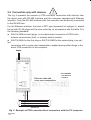
1
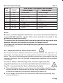
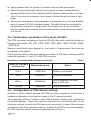
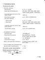
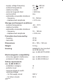
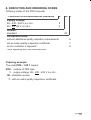
RS-485/ETHERNET CONVERTER PD8 TYPE USER’S MANUAL 1 2 RS-485/ETHERNET CONVERTER PD8 TYPE USER’S MANUAL CONTENTS 1. APPLICATION ...............................................................................................5 2. PD8 CONVERTER SET .................................................................................5 3. INSTALLATION AND BASIC SAFETY REQUIREMENTS .........................10 3.1. Converter installation ............................................................................12 3.2. PD8 electrical connections ....................................................................12 3.3. Connection way with devices ................................................................14 3.4. Requirements for lead-out connections ................................................15 3.5. Transmission parameters of the serial interface ...................................16 3.6. Configuration of PD8 network settings ..................................................16 3.6.1. Installation of the « PD8Config.exe » software ...........................17 3.6.2. Description of the configuration software....................................17 3.7. Capabilities to configure PD8 ................................................................19 3.7.1. Installation of the PD8 configuration applet service component on a PC computer ....................................................20 3.7.2. Notes concernig the configuration applet in the user’s browser ..................................................................20 3.7.3. Change of authorisation data......................................................21 4. OPERATION MODE WITH REALPORT SERVICE ....................................22 4.1. 4.2. 4.3. 4.4. Information about RealPort service controller files................................23 Example of controller installation in Windows XP .................................23 Configuration of RealPort controller in Windows XP .............................24 Example of LUMEL HEAT and LUMEL ENERGY configuration to co-operate with PD8..........................................................................26 3 5. SERIAL BRIDGE MODE WITH UDP PROTOCOL .....................................27 5.1. 5.2. 5.3. 5.4. Settlement of serial link transmission buffering .....................................27 Operation configuration of the serviced client .......................................28 Setting of the serial transmission server ...............................................29 Managing of the service server .............................................................30 6. SERIAL BRIDGE MODE WITH TCP SERVICE..............................................31 6.1. Settlement of serial link transmission parameters.................................31 6.2. Setting of the serial transmission buffering ...........................................31 6.3. Managing of the service server .............................................................32 7. TECHNICAL DATA ......................................................................................33 8. ORDERING CODES ....................................................................................35 9. MAINTENANCE AND GUARANTEE ..........................................................36 4 1. APPLICATION The PD8 converter allows to transmit data to the master devices through the computer network of Ethernet type, to devices equipped with the RS-485 and RS-232 interface. The converter is available in two versions concerning its operation manner: RealPort network service and serial bridge with UDP protocol. In the version nr 1, the PC computer with the Ethernet network card is the connected master device. In the version nr 2, the converter co-operates with the device with the master function and the RS-485 and RS-232 serial interface. The version nr 1 of the PD8 converter requires the installation of a programmed controller of the virtual serial port on the PC computer with the Windows system. This controller ensures to present-days master systems, e.g. LUMEL-HEAT and LUMEL-ENERGY systems, the possibility to transmit data between devices with RS-485 or RS-232 interface, through the Ethernet network, thanks the use of converters of PD8 type (Fig. 1). The converter used in this manner enables to co-operate only with one master computer in the giving moment. In case of using PD8 for servicing MODBUS and LUMBUS industrial protocols - its correct co-operation with master systems on a PC depends on their built-in mechanisms to control break-time intervals between received transmission characters. When using PD8 in the version nr 2, one can develop the RS-485 bus with successive segments by means of additional PD8 converters and the local Ethernet network. The suitable configuration, at least of one pair of converters, allows to obtain their operation in the serial bridge mode (Fig. 3.). The configuration of their operation is also possible in the mode „one-to-several” ( in the shape of a set including maximally 65 converters - Fig. 4.) The version nr 2 operates in the local Ethernet network servicing the UDP datagram protocol. 2. PD8 CONVERTER SET The converter set is composed of: - PD8 converter 1 pc - PD8 user’s manual 1 pc - warranty card 1 pc - mini CD with software 1 pc When unpacking the converter, please check the delivery completeness and whether the type and version code on the data plate correspond to the order. 5 6 RS-485 Permanent private Address IP 192.168.0.145 PD8 ETHERNET PD21 concentrator RG24 controller N12 meter Fig. 1. Exemplary application of the PD8 converter (version Nr1) in a local computer network. PC computer Distinct individual address IP: 192.168.0.1 ETHERNET Local network N10 meter 7 INTERNET Permanent public IP Address: pd8.lumel.com.pl PD8 RS-485 ETHERNET Router PD21 concentrator N10 meter RG24 controller N12 meter Fig. 2. Exemplary application of the PD8 converter (version nr 1) in an vide area computer network. PC computer Distinct public IP Address: Station.lumel.com.pl ETHERNET Router RS-485 8 PD8 IP address: 10.0.2.162 PD8 IP address: 10.0.2.161 ETHERNET RS-485 N12 meter RG24 controller Fig. 3. Exemplary application of the PD8 converter (version nr 2) in the serial bridge mode. PC computer IP address: 10.10.0.1 RS-485 ETHERNET Local network 9 IP address: 10.0.2.160 PD8 Local network IP address: 10.0.2.65 PD8 RS-485 IP address: 10.0.3.1 Network of devices with serial interface Network of devices with serial interface Fig. 4. Exemplary application of the PD8 converter (version nr 2) in the „one-to-several„ mode. Supervising device with serial interface RS-485 PD8 RS-485 3. INSTALLATION AND BASIC SAFETY REQUIREMENTS Symbols located in this service manual mean: WARNING! Warning of potential, hazardous situations. Especially important. One must acquaint with this before connecting the converter. The non-observance of notices marked by these symbols can occasion severe injuries of the personnel and the damage of the instrument. CAUTION! Designates a general useful note. If you observe it, handling of the converter is made easier. One must take note of this, when the instrument is working inconsistently to the expectations. Possible consequences if disregarded ! In the security scope the converter meets the requirements of the EEC Low-Voltage Directive (EN 61010 -1 issued by CENELEC). Remarks concerning the operator safety: 1. General The PD8 converter is destined to be mounted on a panel. Non-authorized removal of the required housing, inappropriate use, incorrect installation or operation creates the risk of injury to personnel or damage to equipment. For more detailed information please study the User’s Manual. All operations concerning transport, installation, and commissioning as well as maintenance must be carried out by qualified, skilled personnel and national regulations for the prevention of accidents must be observed. According to this basic safety information, qualified, skilled personnel are persons who are familiar with the installation, assembly, commissioning, and operation of the product and who have qualifications necessary for their occupation. 2. Transport, storage Please observe the notes on transport, storage and appropriate handling. Observe the climatic conditions given in Technical Data. 3. Installation The meter must be installed according to the regulation and instructions given in this User’s Manual. Ensure proper handling and avoid mechanical stress. 10 Do not bend any components and do not change any insulation distances. Do not touch any electronic components and contacts. Instruments may contain electrostatically sensitive components, which can easily be damaged by inappropriate handling. Do not damage or destroy any electrical components since this might endanger your health! 4. Electrical connection Before switching the instrument on, one must check the correctness of connection to the network. In case of the protection terminal connection with a separate lead one must remember to connect it before the connection of the instrument to the mains. When working on live instruments, the applicable national regulations for the prevention of accidents must be observed. The electrical installation must be carried out according to the appropriate regulations (cable cross-sections, fuses, PE connection). Additional information can be obtained from the user’s guide. The documentation contains information about installation in compliance with EMC (shielding, grounding, filters and cables). These notes must be observed for all CE-marked products. The manufacturer of the measuring system or installed devices is responsible for the compliance with the required limit values demanded by the EMC legislation. 5. Operation Measuring systems including PD8 converters, must be equipped with protection devices according to the corresponding standard and regulations for prevention of accidents. After the converter has been disconnected from the supply voltage, live components and power connections must not be touched immediately because capacitors can be charged. The housing must be closed during operation. 6. Maintenance and servicing Please observe the manufacturer’s documentation. Read all product-specific safety and application notes in this User’s Manual. Before taking the converter housing out, one must turn the supply off. The removal of the converter housing during the guarantee contract period may cause its cancellation. 11 3.1 Converter installation The PD8 converter is foreseen to be installed on a 35 mm DIN rail in accordance with the fig. 3. 120 9 10 11 12 13 14 15 16 1 100 2 3 4 5 6 7 8 45 Fig. 3. Overall and assembly dimensions 3.2. PD8 electrical connections The supply and external signals must be connected acc. to fig. 4 and 5 and tables 1 and 2, in which the assignment of particular PD8 converter lead-outs have been described. There are three diodes on the converter frontal plate: Green - signalling the supply switching on Red (RxD) - signalling the data reception through RS-485 Yellow (TxD) - signalling the data broadcasting through RS-485 12 Description of PD8 converter leads-out Terminal SUPPLY Terminal description 5 Mass of RS-485 interface with optoisolation 6 Line B of RS-485 interface with optoisolation 7 Line A of RS-485 interface with optoisolation 8 Output +5V (for busbar polarization) 9,10 Fig.4 External connections of the PD8 converter Lines to supply the converter 12 RxD output of RS-232 interface with optoisolation 13 TxD input of RS-232 interface with optoisolation 14 Mass of RS-232 interface with optoisolation 15 DSR input of RS-232 interface with optoisolation 16 DTR output of RS-232 interface with optoisolation In the RJ-45 socket of the Ethernet interface 2 diodes are located: green (ACT) - signalling the network activity of the device (transmission or reception) orange (LNK) - signalling the active network connection Description of RJ-45 socket signals Fig. 5 Frontal view of the RJ-45 Ethernet interface socket Table 1 No Signal Description 1 2 3 4 5 6 7 8 TX+ TXRX+ EPWR+ EPWR+ RXEPWREPWR- Transmission + Transmission Reception + (no used) (no used) Reception (no used) (no used) Table 2 13 3.3 Connection way with devices The fig. 6 presents the manner of PD8 converter connection with devices from the object side with RS-485 interface and the computer equipped with Ethernet interface. From the RS-485 interface side, the converter can be directly connected to the RS-485 bus. For the Ethernet interface, the twist of STP type (screened) of category 5, should be set with RJ-45 plugs and the wire colouring (in accordance with the table 3) in the following standard: EIA/TIA 568A for both plugs, in so-called direct connection of PD8 to the network concentrator (hub), or network switch (switch). EIA/TIA 568A for the first plug or EIA/TIA 568B for the second plug in so-called connection with a cross-over transposition, applied among other things in the direct PD8 connection to the computer. Supply ZASILANIE A GND B Ethernet cable with cross-over transposition PC computer with Ethernet interface A B GND MAGISTRALA RS-485RS485 bus Fig. 6 Example of PD8 converter direct connection with the PC computer 14 Wire colouring in RJ-45 plug Table 3 Wire colour in accordance with standard Wire No Signal 1 2 3 4 5 6 7 8 TX+ TXRX+ EPWR+ EPWR+ RXEPWREPWR- EIA/TIA 568A White-green Green White-orange Blue White-blue orange White-brown brown EIA/TIA 568B White-orange orange White-green Blue White-blue Green White-brown brown NOTE: Because of electromagnetic interference, one must use screened wires to connect RS-485 interface signals. The screen must be connected to the protective terminal in one point. The supply must be connected with a two-wire cable with an appropriate wire diameter, ensuring its protection by means of a fusible cut-out. The remove of the converter housing during the guarantee period will cause its invalidation. 3.4. Requirements for lead connections Occurring in practice, different interference sources influence the converter in a permanent or pulse way from the supply network side because of other devices’ action. The level of this interference should be reduced to a value smaller than the resistance threshold, first of all, through the appropriate installation of the converter in the object. In order to obtain a full immunity of the converter against electromagnetic Interference in an environment with unknown interference level, it is recommended to observe following principles: There should be a switch or a circuit breaker in the building installation. This element should be situated near the device, easy accessible for the operator. It should be marked as the instrument switching the device off. Do not supply the converter from the network near devices generating high pulsing interference. 15 Apply network filters for groups of modules servicing the same object. Apply the general principle that the wires (group of wires) leading different signals should be led in the possible farthest distance between them (not less than 50 cm) and the crossing of such group of wires should be made at right angle. Taking into consideration electromagnetic interference, one must use shielded wires to connect RS-485 interface signals. The shield must be connected to the protective terminal in a single point. The supply must be connected by two-wire cable with a suitable cross-section ensuring its protection by means of a cut-out. 3.5. Transmission parameters of the serial interface The PD8 converter co-operates from the RS-485 side with industrial devices at following baud rates: 300, 600, 1200, 2400, 4800, 9600, 19200, 38400, 56000, 115200 bit/s. Maximal serial baud rates depend on the length of transmission lines and are presented on the table 4. At a length over 800 m. One must apply a terminator ( a 120 Ohm resistance) which connects terminals „A” and „B” of the PD8 converter. Dependence of maximal baud rate from the line length Table 4 Length of the transmission line Maximal baud rate 100 m 115200 bit/s Without a terminator 200 m 56000 bit/s Without a terminator 800 m 38400 bit/s With a terminator for baud rate > 9600 bit/s 1200 m 9600 bit/s Notes With a terminator 3.6. Configuration of PD8 network settings Similarly to other network devices, the PD8 converter requires at its first start a suitable configuration of settings for needs of the IP network protocol. These settings include: IP address of the PD8 converter, subnet mask, address of the default gateway. These data must be obtained from the administrator of the computer network, to which the PD8 converter is connected. In case of the converter connection to the local computer network, in which the DHCP service is accessible, the PD8 converter will be configured automatically owing to it. 16 To obtain information about the IP address assigned to the converter, one must start the „PD8Conf.exe” on the PC computer connected to the same computer network as the PD8. 3.6.1. Installation of the „PD8Config.exe” software The installation consists on the copying of the „PD8Conf.exe” software file from the mini CD into the computer catalog indicated by the user. The software can be also directly activated from the mini CD diskette. 3.6.2. Description of the configuration software The „PD8Config.exe” software added to the set serves to configure network settings of the PD8 converter. The software after starting, searches the local computer network and creates the list of accessible converters of PD8 series. The list is displayed in the field „ List of Converters” (fig. 7) The current IP address of the only one converter in the hereby example is visible in the „IP Address” field. If one can see, that the converter has an unsuitable IP address of 0.0.0.0. type, that means, that in the given computer network, the DHCP service does not occur. In such a case, one must configure manually the PD8 converter with the unsuitable address, in the following way: After marking the given converter, click the „Configure IP settings” key, Fig. 7 List of accessible PD8 converters 17 In the revealed „Set up the IP address” window, one must fulfil the fields with data obtained from the network manager (fig. 8). Leave empty, the field with the password. After pushing the „Apply” key in, one must wait some time till the „Operation carried out successfully” message appears. After confirming the message, one must click from the main window the „Refresh list” command. After a while, the list of accessible converters will be actualised and appears in accordance with the fig.9. The „Reboot converter” command is useful after the succeeding manual network Fig. 8 Configuration of exemplary PD8 network parameters configuration, carried out by remote control through the computer network. Then, new network settings in PD8 are activated only after the reboot start of the converter. The unconditional restart of PD8 can be also performed by pressing the accessible 18 push-button through the hole in the converter housing, after removing the lower terminal 5-8 of the RS-485 terminal. Using the „PD8Config.exe” software, one can easily display the Web page served Fig. 9 Correctly configured PD8 converter by the indexed PD8. For this purpose, after the converter indication from the list, one must click the „open Web Interface push-button”, what occasions the start of the default internet browser being in the standard accessory of any contemporary user’s computer. The PD8 converter Web page contains the application which requires the presence of an appropriate service software in the computer. Information concerning the installation of this service are included in the section 3.7.5 of this user’s manual. 3.7. Capabilities to configure PD8 The PD8 converter with factory settings is protected by the user’s name and its password against non-authorised changes in the network configuration and commands to restart the converter again. The default user is „root, which has the „dbps” password. These data can be modified thanks to the configuring applet on the Web page of 19 the given PD8 which is called by the user by means of the internet browser installed on its PC computer. 3.7.1. Installation of the PD8 configuration applet service component in PC The embedded applet (application of the Java language) in the user’s computer. This service is being accessible after installing the Java JRE service package in the windows system. The package adds the starting plug (plug-in) to the internet browser by means of which, the user opens the Web page with the applet. The PD8 converter applet requires the JRE package in 1.4.0 versions or higher. For this reason, before the first opening of the PD8 page in the user’s browser, one must start the installator of JRE package which exists in the „Java JRE” catalogue on the PD8 CD disk. To install the applet service package into the user’s PC, one must carry out following operations: 1. Start the file with extension of the (.exe in the „Java JRE” catalogue of the CD disk. 2. Select the „I accept the terms in the license agreement” in the shown installator window and click „Next”. 3. Select the „typical” option and click „Next”. 4. (Optional Installator step). Mark accessible browsers in the computer and click „Next”. 5. After finishing the installation, click „finish” in the installator window. 6. Call the PD8 Web page in the browser in order to check the JRE installation correctness. 7. Press the „always” push-button in the new window with the „Warning security” title, the appearance of which means the query about acceptation of the digital signature of the being started applet by the user. 8. Close the browser. 3.7.2. Remarks about the configuration applet in the user’s browser After writing the PD8 converter Web address in the browser address bar, the user’s configuration applet appears in a separate window (fig. 10). The left side of the application window includes the menu of accessible commands. The right window panel shows data associated with the command passed by the user in the left panel. Information concerning current operations and errors are given in the lower panel. From the beginning to the end of its action, the applet maintain the TCP/IP communication with the PD8 converter. 20 3.7.3. Modification of authentication data The selection of the „Security” command application from the left panel enables the managing of the PD8 user’s authentication (Fig. 11). By means of the „Enable password authentication” option in the right window panel, we can decide about the authentication switching on and off at restart trials and configuration modifications of PD8. Fig. 10 Welcome page of user’s application In case of the option switching on, one must introduce the required user’s name and write the password twice. Data will be written into the converter memory after pressing the „Save” key. In case of the own password forgetting, one can set its default value by restoring factory settings in PD8. For this aim the RESET push-button accessible after removing the lower terminal 5-8 of the RS-485 converter interface is used. 21 Fig. 11 Procedure of switching the authentication on by the password To restore factory converter settings one must: 1. switch the converter supply off, 2. push the RESET push-button and holding it down, switch the converter supply on, 3. release the RESET push-button after obtaining the converter operation readiness (16 seconds). 4. OPERATION MODE WITH THE REALPORT SERVICE The PD8 converter includes the licensed by DiGi inc. company the RealPort network service enabling the communication by means of the Ethernet link with PC computers, operating under the supervision of Windows operation system. The 22 installation of the RealPort service in the Windows system causes the addition of the next, so called COM virtual serial port to the list of accessible ports in the given computer. This port does not have a physical hardware form but a virtual one - thanks to the programmed work emulation of a typical serial link. The application of additional virtual COM ports allows to replace the serial communication by the Ethernet communication. The PD8 converter design allows to obtain in the given time, only one network connection of the RealPort service. That means that only one PC computer of any IP address can communicate with the given computer through the virtual serial port. For other computer, this service is inaccessible in the given moment and for this reason a suitable message about the error appears on their screens. 4.1. Information about RealPort service driver files Files of the RealPort service driver are accessible on enclosed mini CD. Versions for two different Windows systems are in two catalogues: - version for MS Windows 98 and MS Windows Me, - version for MS Windows 2000, MS Windows XP. Depending on the system version, one must install the suitable version of the RealPort driver in the operator computer. Details of the service driver installation for Windows systems are accessible on the Web page of each PD8 converter. 4.2. Example of the driver installation in XP Windows In order to install the RealPort service driver in the popular operating system presented by Microsoft Windows XP, one must carry out following operations (the installation in other Windows versions differs insignificantly). Follows these steps to install RealPort on Microsoft Windows XP 1. Click „Start”, click „Settings”, and then click „Control Panel”. 2. Double-click „Add/Remove Hardware” to start the Add Hardware Wizard. Click „Next”. NOTE: The Add/Remove Hardware Wizard is searching for new devices. 3. Click „Yes, I have already connected the hardware” and click”Next”. 4. Scroll down to the bottom of the Installed Hardware list, select „Add a new hardware device”, and then click”Next”. 23 5. Click „install the Hardware that I manually select from the list (Advanced” and click „Next”. 6. In the „Common hardware types” list, select”Multi-port serial adapters” and click „Next”. 7. Click „Have disk...”. 8. Type the path to the RealPort files and click „OK”, or click”Browse” and locate the files. 9. Select „digirp.inf”, click „Open”, and then click”OK”. 10. Mark the installed device „ Standard RealPort device” in the „Model” list (or click „Digi Connect ME” in the case of Windows 98/ME), click „Next” and click „Next” again. 11. Introduce the IP address of the PD8 converter in the dialog window „Add Digi Hardware Wizard” and remain the port number unchanged, as (771). Click „Next”. 12. In the case of Windows 98/ME, introduce the proper name (e.g. Test) for the PD8 converter in order to the easy identification during the operation. Leave the number of PD8 converter serial ports unchanged as (1). 13. Click „Next” and then „Finish”. 14. confirm successive messages. 4.3. Configuration of the RealPort driver in Windows XP After carrying out the successful installation in accordance with the previous item, one must additionally configure the RealPort driver by means of the Manager of windows system devices. For this purpose, one must perform following steps: 1. click the „Start” push-button, point the „settings” command and click the „Control Panel” command. 2. Click twice the „System” icon to open the System properties” window. Choose the „System” tab and click the „Device manager” push-button. 3. After the „Device administrator” window appearance (fig. 12), unroll the „Ports (COM and LPT)” branch in the tree of accessible devices. One can see that in the exemplary Windows system, three serial ports are accessible: COM1, COM2. As the result of the RealPort controller installation in the system, a successive port is accessible - virtual - COM3, denoted as Digi RealPort (fig.12). 4. Unroll the „Multiport serial adapters” branch which shows the installed PD (visible as” Digi Connect ME” in the Windows 98 system.. 24 5. Click twice on the converter name to obtain the „ Test properties” window: (fig. 13). 6. Select the „Advanced” tab and click on the „Properties...” push-button. 7. In the appeared „...Advanced properties” window (Fig. 13) click the „Port 1 COMx” branch and next choose the „Properites” overlap, click „Set profile” and mark the option: „Throughput-Optimized TCP”, in accordance with the example on the fig. 13. 8. Confirm modifications by the „OK.” push-buttons in windows. Fig. 12 Exemplary list of devices in the Windows system. 25 Fig. 13. Advanced Driver settings. 4.4. Example of Lumel Heat and Lumel Energy configuration to co-operate with PD8 converters Lumel Heat and Lumel Energy systems communicate with industrial devices by means of COM serial ports. After installing additional virtual COM serial ports, one can reffer to them in systems of Lumel series. Then, one must introduce or modify supervising appeals to added virtual ports in new or existing applications. Lumel Energy softwares in versions older than 2.5, service maximally 4 serial ports, and in such systems, virtual serial ports must be installed as COM1...4. One must correct the parameter of the maximal response time for the slave devices (timeout) accessible in master devices to the correct value for PD8. 26 The delay value can be maximally 1000 ms and depends on: maximal response time of slave devices with MODBUS protocol and RS-485 interface, flow capacity of the Ethernet network, which the PD8 converter is connect to. 5. SERIAL BRIDGE MODE WITH UDP PROTOCOL The converter operation in the serial bridge mode enables the expansion of the RS-485 bus by successive segments by means of additional PD8 converters and the Ethernet network. The bridge configuration in the local area allows to create maximally 65 accessible points between the RS-485 and Ethernet network, using 65 PD8 converters. The service configuration of the serial bridge for the given converter can be divided on 4 stages: determination of serial link transmission parameters, switching the service client on, definition of addresses and IP ports for other converters which have to retransmit serial data frames, definition of the operation way for the mechanism buffering frames of the serial transmission protocol, switching the service server on the given IP port of the configured converter. The setting of the serial bridge operation way is carried out by using the configuration application on the Web page of the given PD8, which is called by the user by means of the internet browser installed in his PC computer. 5.1. Settlement of serial link transmission parameters The selection of the „Serial Port” command application from the left panel, causes the display of the current setting list on the right panel, concerning the converter operation. In the first „Basic” tap, the user has the possibility to change parameters of the converter RS-485 port (Fig. 14). When setting transmission parameters, one must remember to set the identical type of transmission word for each connected converter. The baud rate can be different between segments but consistent with settings of connected devices to the given RS-485 segment. 27 Fig. 14. Setting of converter serial port parameters 5.2. Configuration of service client operation The configuration of the bridge client is carried out after choosing by the user, the second tab „Network services” in the right panel „ Serial port configuration (fig 15). To begin the configuration process, one must previously switch the „Enable UDP client” on. Fields of addresses and converter IP ports, which have to retransmit frames of serial data, are fulfilled acc. to following principles: In case of connection in the relation 1 to 1, define in each converter the address and IP port of the remaining converter being in relation. In case of connection in the relation 1 to several, set in each slave converter the address and IP port of the master converter. However, in the only master converter set all (maximally) 64 addresses and ports slave converters remaining in relation. The default number of the IP port for the serial bridge service is 2000. In case of a local conflict occurrence with another network service in the given network, which uses the same port - there is the possibility to change its number - both for the bridge service server and for the client. 28 Fig. 15. Setting of the UDP client for the serial bridge. 5.3. Setting of the serial transmission buffering In the „ Network port services” tab, there is also the possibility to change the way of serial transmission buffering (Fig. 17) The use of the buffering mechanism is indispensable in the case of frame retransmission of the MODBUS or LUMBUS industrial protocol. The definition of the number of milliseconds of silence allows to detect the end of the MODBUS RTU frames, after which, their retransmission should follow through the Ethernet network. The additional parameter defining the buffer dimension enable to protect against its overflow or the transmission deadlock. 29 5.4. Management of the service server The configuration of the bridge server is carried out after choosing by the user the third „Network services” tab being in the right „Serial port configuration” application (Fig. 16). The start of the bridge service sever in the given converter is carried out after giving the number of the IP port and pointing the „Enable UDP server” option. After introducing all changes in the „Serial port configuration” panel, one must write the converter memory, pressing the „Save” pushbutton. Fig 16. Switching the UDP server on the given port. 30 6. OPERATION MODE WITH THE SOCKET TCP SERVICE The work with TCP socket is a working mode very similar to the mode with Real Port service. The difference consists only on the communication way with the PD8 device, where in this case we make use of the direct connection TCP/IP, giving the IP address of the PD8 device and the port number. One can divide the service configuration of the TCP Socket of the given converter in three stages: determination of serial link transmission parameters, definition of the operation way for the mechanism buffering frames of the serial transmission protocol, switching the service server on the given IP port of the configured converter. The setting of the serial bridge operation way is carried out by using the configuration application on the WWW page of the given PD8, which is called by the user by means of the internet browser installed in his PC computer. The design of the PD8 converter allows to obtain in the given time, only one network connection of the Socket TCP service. That means, that only one PC computer of any IP address and set port can communicate with the given converter. For remaining computers, the service is inaccessible in the given moment, and in relation to that, a suitable message about the error appearson their screens. 6.1. Settlement of serial link transmission parameters The settlement of transmission parameters of the serial link is carried out according to the section 5.1. 6.2. Setting of the serial transmission buffering The settlement of transmission parameters of the serial link is carried out according to the section 5.3. 31 6.3. Managing of the service server The configuration of the TCP service server is carried out after choosing the third tabbed page “ Network services”, located in the right application panel “configuration of the serial port” ( Fig. 17.). The start of the service server in the given computer is performed after marking the “Connect the TCP server” option and giving IP port number. After introducing all changes in the “Serial port configuration” panel, one must write them in the converter memory, pressing the “Write” key. Option: „Switch the server on” Port number Fig.17 Schwitching the TCP server on the given port. 32 7. TECHNICAL DATA Transmission data: – RS-485 interface: - data format - baud rate of RS-485 port - maximal response time to the query frame - transmission range 9, 10, 11, 12 [bit] 300, 600, 1200, 2400, 4800, 9600, 19200, 38400, 56000, 115200 bit/s 1000 ms up to 1200 m at 9600 bit/s – RS-232 interface - data format 9, 10, 11, 12 bits - baud rate 300, 600, 1200, 2400, 4800, 9600, 19200, 38400, 56000, 115200 bit/s - maximal response time to the query frame 1000 ms - transmission range up to 15 m at 9600 bit/s – ETHERNET interface: - interface type - transmission protocol - baud rate - transmission range – Status and data flow indicators 10/100Base-T Digi RealPort§, TCP/IP, HTTP, ICMP, DHCP, ARP 10, 100 Mbit/s up to 100 m 5 diodes (supply, RxD, TxD, ACT, LNK) – Time to obtain the readiness from the moment of switching on 16 s Converter power consumption x 5 VA Rated operation conditions: - supply voltage 85...230...253 V or 20...24...50 V a.c./d.c. 33 - supply voltage frequency - ambient temperature - relative humidity - external magnetic field - work position - admissible sinusoidal vibrations: - frequency - displacement amplitude 40...50...440 Hz -20...23...45°C < 85% < 400 A/m any 10...150 Hz x 0.15 mm Storage and transport conditions: - ambient temperature -20... 70°C - relative humidity < 85% - admissible sinusoidal vibrations: - frequency 10... 150 Hz - displacement amplitude x 0.35 mm Protection level ensured by: - housing - terminals IP 30 IP 20 Dimensions 45 100 120 mm Weight 0.2 kg Housing adapted to be mounted on a 35 mm rail acc. to EN 60715:2002. Electromagnetic compatibility: - immunity against interference - emission of radio noise Safety requirements: acc. to EN 61010-1: - installation category - pollution level - maximal phase-to-earth working voltage: - for the supply circuit - for other circuits 34 acc. to EN 61000-6-2 acc. to EN 61000-6-4 III 2 300 V 50 V 8. EXECUTION AND ORDERING CODES Ordering codes of the PD8 converter Converter of RS-485/Ethernet interfaces Supply voltage: 85...230...253 V a.c./d.c. 20...24...50 V a.c./d.c. Version: standard Acceptance tests: without additional quality inspetion requirements wit an extra quality inspection certificate acc.to customer’s requests * X XX X 1 2 00 8 7 X * after agreeing with the manufacturer Ordering example: The code PD8 - 1 00 7 means: PD8 - module of PD8 type 1 - supply voltage: 85...230...253 V a.c./d.c. 00 - standard version 7 - with an extra quality inspection certificate. 35 9. MAINTENANCE AND GUARANTEE The PD8 converter does not require any periodical maintenance. In case of some incorrect operations: 1. After the dispatch date and within the period stated in the guarantee card One should return the converter to the manufacturer’s Quality Inspection Dept. If the converter has been used in compliance with the instructions, the manufacturer guarantees to repair it free of charge. The disassembling of the housing causes the cancellation of the granted guarantee. 2. After the guarantee period: One should send the instrument to repair it in an authorized service workshop. Spare parts are available for the period of five years from the date of purchase. Our policy is one of continuous improvement and we reserve the right to make changes in design and specifications of any products as engineering advances or necessity requires and revise the above specifications without notice. 36 37 Tel.: (48-68) 329 51 00 (exchange) Fax: (48-68) 329 51 01 e-mail:[email protected] http://www.lumel.com.pl Export Department: Tel.: (48-68) 329 53 02 Fax: (48-68) 325 40 91 e-mail: [email protected] PD8-09E 20.06.2012 Lubuskie Zak³ady Aparatów Elektrycznych LUMEL S.A. ul. Sulechowska 1, 65-022 Zielona Góra, Poland