1
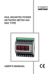
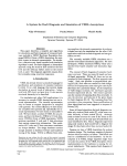
TEMPERATURE
and HUMIDITY
TRANSDUCER
P19 TYPE
USER’S MANUAL
1
2
Contents
1. APPLICATION .................................................................. 5
2. TRANSDUCER SET .......................................................... 5
3. BASIC REQUIREMENTS, OPERATIONAL SAFETY ....... 6
4. INSTALLATION .................................................................. 6
4.1. Overall dimensions and working position ................... 6
4.2. Electrical connections................................................. 7
4.3. Assembly .................................................................... 8
5. SERVICING ...................................................................... 10
5.1. Messages after supply is switched on ...................... 10
5.2. Functions of the P19 transducer .............................. 10
5.2.1. Calculated values .................................................. 11
5.2.2. Default parameters ................................................ 12
6. MODBUS PROTOCOL ON RS-485 SERIAL PORT ....... 12
6.1. Serial interface connection ....................................... 12
6.2. Description of the MODBUS protocol ...................... 13
6.3 Description of implemented MODBUS functions....... 13
6.4 Register map ............................................................. 18
6.5 Read/Write registers .................................................. 19
6.6 Read only registers ............................................... 21
7. EMERGENCY RESTORATION OF RS-485 PARAMETERS......22
8. TECHNICAL DATA .......................................................... 23
9. ORDERING CODE ........................................................... 25
3
4
1. APPLICATION
The P19 transducer is device destined for the continuous
measurement and conversion of relative humidity and ambient temperature into a digital form (protocol MODBUS RS-485). The transducer is
fixed on a wall. The programming of the transducer is possible by means
of the RS-485 interface.
Fig. 1. View of the P19 transducer.
2. TRANSDUCER SET
The delivered controller set is composed of:
1. transducer P19 ................................... 1 pc
2. user’s manual ..................................... 1 pc
3. guarantee card.................................... 1 pc
5
3. BASIC REQUIREMENTS, OPERATIONAL SAFETY
In the security scope, the transducer meets the requirements
of the EN 61010 -1 standard.
Remarks concerning the operator safety:
l
All operations concerning transport, installation, and commissioning
as well as maintenance must be carried out by qualified, skilled
personnel.
l
Before switching the transducer on, one must check the correctness
of connections to the network.
l
The device is destined to be installed and used in industrial
electromagnetic environment conditions.
When unpacking the P19 transducer, please check whether the type
and version code on the data plate correspond to the order code.
4. INSTALLATION
4.1. Overall dimensions and working position
The P19 transducer is designed to be mounted on a wall
by means of a screw connection. Transducer housing is assembled
of two parts: front part and back part. The transducer has screw
connectors placed inside the transducer, which enable the connection
of external wires of 1 mm2 cross-section.
80
25
120
6
Fig. 2. Overall dimensions of the P19 transducer and correct
working position
Fig. 3. Lay-out of assembly holes in back part of housing
4.2. Electrical connections
The P19 transducer has 4 connecting terminals to which
there is access after removing the front part of the transducer
housing.
ZW
J2
J1
Fig 4. Marking of terminals for the connection of external signals
7
Fig. 5. Way of electrical signal connection
Transducer is equipped with two LED indicator: RX (green
color) , TX (red color), which indicates the state of RS-485 communication lines. Indicators works only first 60 sec after power is on or after
switching “ZW” jumper (section 7).
4.3. Assembly
On the beginning one must separate front part of housing from back
part of housing with printed circuit board using flat screwdriver as
shown on Fig. 6.
Fig. 6. Disassembly housing method
8
Back part of housing is equipped with hole at the middle
of housing through which electrical cords should be passed. Then
back part of housing should be screwed on to the wall. Electrical cords
should be passed through the hole on the printed circuit board (Fig. 7)
and connected to the screw connectors with the right way (Fig. 5)
Fig. 7. The way of assembly electrical cords
After connecting cords and pushing the front part of housing transducer
is ready to work.
To connect the input signals in an environment with high interference, one must apply shielded wires. The shield must be connected
to the nearest PE point from the feeder side.
9
5. SERVICING
After connecting cords, closing the housing, and connecting
to the supply, the transducer is ready to work with manufacturer’s settings
(table 2). The transducer can be programmed through the RS-485 interface.
One can program following parameters in the transducer:
- communication parameters
- averaging time of the measurement
There is the possibility to connect the transducer through another
transmission media, like: ETHERNET, USB, using LUMEL S.A.’s
converters.
5.1. Messages after supply is switched on
After connecting external signals and switching the supply on,
the transducer indicates its ready to work by switching on two LED
indicators RX(green color) i TX(red color). After about 5 seconds,
the transducer automatically switches to the mode in which it measures
and converts into the digital value.
5.2. Functions of the P19 transducer
l
measurement of ambient temperature and relative humidity,
l
calculation of chosen physical quantities (dew-point temperature,
absolute humidity),
l
memory storage of maximal and minimal values for each of the
measured and calculated value,
l
programming of the measurement averaging time,
l
RS-485 interface servicing in the MODBUS protocol, in RTU mode.
10
5.2.1. Calculated values
Based on measured temperature and relative humidity
the P19 transducer calculates dew-point and absolute humidity from
the following relations.
DP → dew point:
Tn
DP=
m
(
RH
log Pws .
10000 . A
AH → absolute humidity:
AH= 2.1668 .
)
-1
Pws . RH
100 . (T + 273.2)
where:
T → measured temperature [oC]
RH → measured relative humidity [%]
DP → dew-point temperature [oC]
Pws → pressure of the satured water vapor
(water vapor pressure) [mbar]
AH → absolute humidity [g/m3]
Table 1
Coefficients used for the dew-point calculations
T [oC]
A
m
Tn
<0
6.119866
7.926104
250.4138
0 … 50
6.1078
7.5
237.3
50 ...100
5.9987
7.3313
229.1
11
5.2.2. Default parameters
Table 2 shows the default parameters of P19 transducer.
These settings can be restored using the RS-485 interface by writing
into the 4009 register the value „1”.
Table 2
Parameter
description
Parameter
address
Default
value
Address
4001
1
Baud rate
4002
9600
Mode
4003
RTU 8N2
Averaging time
4005
30 [s]
When standard communication parameters have been changed and the new configuration has been lost, one can set temporary parameters by switching the jumper marked with the symbol “ZW” (section 7).
6. MODBUS PROTOCOL ON RS-485 SERIAL PORT
Digital P19 transducers are equipped with serial RS-485 link
port with implemented MODBUS protocol to enable digital communication
between computer systems and other devices which have
MODBUS Master functions implemented. The implemented protocol
is in compliance with thePI-MBUS-300 Rev G Modicon Company
specification.
6.1. Serial interface connection
Standard RS-485 port allows direct connection of up to 32
devices on a single serial link with a length of 1200 m (at a baud rate
of 9600 b/s). To connect more devices it is necessary to use additional
intermediate-separating devices.
12
Interface line location are shown in the figure 5. To obtain
a correct transmission it is necessary to connect the A and B line
parallel with their counterparts in other devices. To connect to the PC,
the RS-485 interface card or the converter, e.g. PD10 is required.
6.2. Description of the MODBUS protocol
The implemented protocol is in compliance with the PI-MBUS300Rev G Modicon Company specification. Parameters of the transducer serial link :
transducer address
1..247
baud rate:
4800, 9600, 19200, 38400, 57600 [b/s]
working modes:
RTU: 8N2, 8E1, 8O1, 8N1
maximal response time:
500 ms
The configuration of serial link parameters consists on settlement of baud rate, device address and protocol (working mode).
Note: Each transducer connected to the communication network must
have:
l
unique address, different from other devices connected to
the network,
l
the same baud rate and information unit type (working
mode).
6.3 Description of implemented MODBUS functions
Functions of the Modbus protocol implemented in P19 transducer::
l
03 (03h) – Read Holding Registers
l
04 (04h) – Read Input Registers
l
06 (06h) – Write Single Register
13
l
16 (10h) – Write Multiple registers
l
17 (11h) – Report Slave ID.
Read Holding Registers (code 03h)
Example 1. Reading two float(32 bits) registers, first register address
is 1D4Dh (7501) , register values (7501, 7502): 25.68, 20.25.
Request:
Table 3
Device
address
01h
Function
Register
address
03h
Number
of registers
CRC
B1
B0
B1
B0
1Dh
4Dh
00h
02h
5270h
Response:
Device
address
Function
Number
of bytes
Table 4
B3
01h
03h
08h
41h
1DB0h (7501)
1DB1h (7502)
CRC
B2
B1
B0
B3
B2
B1
B0
CDh
70h
A4h
41h
A2h
00h
00h
83D0h
Example 2 . Reading two float 32-bit registers (7501,7502) located
in 2x2 following 16-bit registers (7002, 7003, 7004, 7005), first register
address is 1B5Ah (7002) – 32-bit register values : 25.68, 20.25.
14
Request:
Table 5
Device
address
01h
Function
Register
address
03h
Number
of registers
CRC
B1
B0
B1
B0
1Bh
5Ah
00h
04h
62FEh
Response:
01h
03h
Number
of bytes
Device
address
Function
Table 6
08h
Register
value
1B5Ah
(7002)
Register
value
1B5Bh
(7003)
Register 7501 (32 bit)
value
Register
value
1B5Ch
(7004)
Register
value
1B5Dh
(7005)
CRC
Register 7502 (32 bit)
value
B3
B2
B1
B0
B3
B2
B1
B0
41h
CDh
70h
A4h
41h
A2h
00h
00h
83D0h
Example 3. Reading two float 32-bit registers (7501,7502) located in
2x2 following 16-bit registers (6002, 6003, 6004, 6005), first register
address is 1772h (6002) - 32-bit register values : 25.68, 20.25.
Request:
Table 7
Device
address
01h
Function
03h
Register
address
Number
of registers
B1
B0
B1
B0
17h
72h
00h
04h
CRC
E1A6h
15
Response:
01h
03h
Number
of bytes
Device
address
Function
Table 8
08h
Register
value
1B5Ah
(7002)
Register
value
1B5Bh
(7003)
Register 7501 (32 bit)
value
Register
value
1B5Ch
(7004)
Register
value
1B5Dh
(7005)
CRC
Register 7502 (32 bit)
value
B1
B0
B1
B0
B3
B2
B1
B0
70h
A4h
41h
CDh
00h
00h
41h
A2h
E411h
Write Single Register (code 06h)
Example 4. Writing value “3” to the register 0FA1h (4001)
Request:
Table 9
Device
address
01h
Function
06h
Register
address
Number
of registers
B1
B0
B1
B0
0Fh
A1h
00h
03h
CRC
983Dh
Response:
Table 10
Device
address
01h
16
Function
06h
Register
address
Number
of registers
B1
B0
B1
B0
0Fh
A1h
00h
03h
CRC
983Dh
Write Multiple registers (code 10h)
Example 5. Writing value “3” and “4” to registers FA1h (4001) and
FA2h (4002)
01h
10h
Table 11
Register
address
Number
of registers
Number of
bytes
Device
address
Function
Request:
B1
B0
B1
B0
0Fh
A1h
00h
02h
04h
Register
value
(4001)
Register
value
(4002)
B1
B0
B1
B0
00h
03h
00h
04h
CRC
8828h
Response:
Table 12
Device
address
01h
Function
Register
address
10h
Number
of registers
B1
B0
B1
B0
0Fh
A1h
00h
02h
CRC
133Eh
Report Slave ID (code 11h)
Example 6. Report slave ID
Request:
Table 13
Device
address
Function
01h
11h
CRC
C02Ch
Response:
Address
Function
Number
of bytes
ID
Device
state
Table 14
Variable bytes depending on
device firmware ver. And serial
number (neg. ver. 0.95, serial
number. 13040001)
01h
11h
08h
D0h
FFh
00h 95h 40h 01h 80h 0Dh
CRC
DFC3h
17
6.4 Register map
In the P19 transducer the data is stored in 16- and 32-bit registers. The process variables and parameters of the device are stored
in the different address space depending on the variable type. The bits
in the 16-bit registers are numbered from the least significant to the most
significant (b0 … b15). The 32-bit registers (4 Bytes) contain floatingpoint values in IEEE-754 standard. Bytes sequence: B3 B2 B1 B0 –
the most significant byte is sent as the first one. 16-bit registers which
represents 32-bit values on a two following registers are multiplied
at different address field with different bytes (word) order. Registers
6000...6024 (B1, B0, B3, B2) , Registers 7000...7024 (B3, B2, B1, B0).
Register map of the P19 transducer is shown in Table 15.
Note:
All the given addresses are physical addresses. In some computer
programs logical addressing is applied, then the addresses should be
increased by 1.
Table 15
Address
Value
Description
range
type
4000
- 4011
integer
(16 bits)
The value is located in the 16-bit register
6000-6024
float
(32 bits)
The value is located in two following 16-bit
registers. Registers contain the same data
as 32-bit registers from the area 7500-7512.
Registers are readout type only. Byte order
(B1, B0, B3, B2)
7000-7024
float
(32 bits)
The value is located in two following 16-bit
registers. Registers contain the same data
as 32-bit registers from the area 7500-7512.
Registers are readout type only. Byte order
(B3, B2, B1, B0)
7500-7512
float
(32 bits)
The value is located in the 32-bit register.
Registers contain measured and calculated
data by the transducer. Registers are readout type only. Byte order (B3, B2, B1, B0)
18
6.5 Read/Write registers
Range
Identifier
r
208
4001
Address
r/w
1...247
4002
Baud rate
of the RS485 link
r/w
0...5
4003
4004
4005
Name
4000
Address
Read(r)/
Write (w)
Table 16
Transmission mode
of the RS485 link
r/w
Acceptation of RS485 link
parameter
changes
r/w
Averaging
time
r/w
0...3
0...1
6...3600
Description
Identifier of the P19 transducer
Device address
Value
Description
0
4800 bit/s
1
9600 bit/s
2
19200 bit/s
3
38400 bit/s
4
57600 bit/s
Value
Description
0
RTU 8N1
1
RTU 8N2
2
RTU 8E1
3
RTU 8O1
Value
Description
0
no changes
1
acceptation of changes
Measurement averaging time [s]
19
4006
4007
20
Erasing of
extremes
Status
register
r/w
r/w
0...1
-32768...
32767
Value
Description
0
no changes
1
Erasing of min and max
value
Transducer
status.
Describe
current state and device configuration. Bits representing specific events.
Value bit ‘1’ means that specific
event occurred.
Bit15
Supply reset, writing value
-32768 ( 8000h ) clears status bit
Bit14
Calibrations
error
Bit13
Incorrect transducer parameters – new parameters
required
Bit12
unused
Bit11
unused
Bit10
Min/max erasing status,
writing value 1024 ( 400h )
clears status bit
Bit9
Temporary communication
parameters set (short circuit
„ZW” jumper)
Bit8
unused
Bit7
Communication with sensor
error
Bit5,6
unused
Bit3,4
unused
Bit2
Exceeding of measurement
averaging time
Bit1
unused
Bit0
unused
parameters
4008
Firmware
ver.
r
1...999
4009
Restore
default
parameters
r/w
0...1
4010
reserved
4011
reserved
Firmware version x100
Value
Description
0
no changes
1
Force restoring default parameters (value of register will
automatically change to “0’)
6.6 Read only registers
Value is place in two
following 16-bit registers, Those register
have the same value
like 32-bit register
from range 7500….
Value placed in
32-bit
registers
Table 17
Name
7000/6000
7500
ID
w
-
P19 identifier
7002/6002
7501
T
w
o
Measured temperature
7004/6004
7502
RH
w
%
Measured relative
humidity
7006/6006
7503
DP
w
o
Calculated dew point
7008/6008
7504
AH
w
g/m
Calculated absolute
humidity
7010/6010
7505
min T
w
o
Min. measured temperature
Read
(r)/
Write
(w)
Unit
C
C
3
C
Description
21
7012/6012
7506
max T
w
o
C
Max. measured temperature
7014/6014
7507
min RH
w
%
Min. measured relative
humidity
7016/6016
7508
max RH
w
%
Max. measured relative
humidity
7018/6018
7509
min DP
w
o
C
Min. calculated dew
point
7020/6020
7510
max DP
w
o
C
Max. calculated dew
point
7022/6022
7511
min AH
w
g/m
7024/6024
7512
max AH
w
g/m
3
Min. calculated absolute
humidity
3
Max. calculated absolute
humidity
7. EMERGENCY RESTORATION OF RS-485 PARAMETERS
When standard communication parameters have been changed and the new configuration has been lost, one can set temporary
RS-485 parameters by switching jumper marked with the symbol „ZW”
(Fig. 4.) Temporary RS-485 parameters are shown below:
l
l
l
address
baud rate
mode
247
9600 kb/s
RTU 8N2
The changes of parameters must be made before removing the jumper,
otherwise the device will return to its previous configuration.
22
8. TECHNICAL DATA
Basic parameters:
- relative humidity range
- relative humidity measurement
accuracy
- hysteresis of measuring
relative humidity
- temperature range
- temperature measurement
accuracy
- calculated values
RS-485 interface:
- protocol
- baud rate
- mode
- maximal response time
Rated operating conditions:
- supply voltage
- power consumption
- ambient temperature
- storage temperature
- relative humidity:
- warm-up time
- insured protection grade
ensured by the housing
- mounting
- weight:
- dimensions
0...100 % 1
±3% in range 10...90%
±5% for the remaining range
± 1%
– 20...60 °C 2
±0.6oC in range 10...40o C
±1.0oC for the remaining
range
absolute humidity (a) [g/m3]
dew point (Td) [°C]
MODBUS slave
4800, 9600, 19200, 38400,
57600 bit/s
RTU: 8N2, 8E1, 8O1, 8N1
500 ms
9...24 V a.c. / d.c.
< 0.3 VA
– 20...23…60 °C
– 30...23…85 °C
< 95% 1
<15 min.
IP 20
on the wall
<0.2 kg
120 x 80 x 25 mm
23
working position:
according Fig. 2.
Galvanic isolation
- between supply and RS-485 interface 1 kV
Electromagnetic compatibility:
- disturbance immunity
- disturbance emission
acc. to EN 61000-6-2
acc. to EN 61000-6-4
Security requirements acc. to EN 61010-1
- installation category
III
- pollution grade
2
- phase-to-earth working voltage
50V
- altitude above sea level
< 2000m
1
2
- In case of condensation of water vapor on the sensor surface,
the error measurement does not exceed the basic error till
the moment of drying up the sensor structure.
- The absolute temperature measurement range is -30...85°C,
but beyond the basic range, the measurement class is not
guaranteed.
24
9. ORDERING CODE
Table 18
P19 - XX X X
Version:
standard
00
custom-made*
XX
Language:
polish
P
english
E
other
X
Acceptance tests:
without extra quality requirements
0
with an extra quality inspection certificate
1
acc. to customer’s requirements*
X
*After agreeing with the manufacturer
Example of Order:
The code: P19 - 00E0 means:
P19 – humidity and temperature transducer
00 – standard version
E – English language version
0 – without additional quality requirements.
25
26
27
LUMEL S.A.
ul. Słubicka 1, 65-127 Zielona Góra, Poland
Export Department:
Tel.: (48-68) 45 75 302
Fax: (48-68) 32 54 091
e-mail: [email protected]
28
P19-09
Tel.: (48-68) 45 75 100
Fax: (48-68) 45 75 508
e-mail:[email protected]
http://www.lumel.com.pl