1
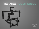
US E R G U I D E
COMPATIBILITY
The MōVI Controller is compatible with the MōVI M5,
M10, and M15 running firmware version 3.08 or later.
Download the latest MōVI firmware and update
instructions at www.freeflysystems.com.
See Follow-Focus Integration section for information on
wireless lens control system compatibility.
CONTROLLER SPECIFICATIONS
POWER INPUTS:
External DC Supply or Battery
Controller Only (No Monitor), Power Level 4
Controller and Monitor, Max.
13.0 V - 20.0 V 0.2 A
13.0 V - 20.0 V 3.2 A
USB
Controller Only (No Monitor), Power Level 4
4.75 V - 5.25 V 0.4 A
12V DC Output
Input 13.0 - 20.0V, Output Current < 3.0A
Max. Current Output
11.4 V - 12.6 V
3.0 A
USB 5V Output
Input 13.0 - 20.0V, Output Current < 2.0A
Max. Current Output
4.50 V - 5.25 V
2.0 A
All Channels
2.410 - 2.465 GHz
Power Level 0 (EU)
Power Level 4
+10 dBm
+18 dBm
Power Level 0 (EU), Outdoor Line-of-Sight
1200 ft / 300 m
Including Antenna, Excluding Monitor and Battery Plate
950 g
Including Antenna and Joystick, Excluding Monitor and Battery Plate
300mm X 175mm X 120mm
Excluding Wires and Mounting Tape
15 g
Excluding Wires, Mounting Tape, Antenna
33mm X 38mm X 15mm
POWER OUTPUTS:
RADIO TRANSMITTER:
Frequency
Transmitter Power
Range
MŌVI CONTROLLER PHYSICAL:
Weight
Dimensions
RECEIVER PHYSICAL:
Weight
Dimensions
MōVI CONFIGURATION:
Any MōVI M5, M10, or M15 can be configured to work with the MōVI
Controller. The MōVI must have firmware version 3.08 or later. The latest
MōVI firmware, release notes, and update instructions are available at
www.freeflysystems.com.
Once running firmware v3.08 or later, change the MōVI Radio Type from
the default (DSMX 2048) to MōVI Controller. This can be done from any of
the Freefly Configurator apps (PC, Mac, Android) in the Remote Controller
Config menu.
The values of the other parameters in this menu (Map Remote Mode, etc.)
do not matter for this Radio Type and can be left at their defaults.
After installing the MōVI Controller Receiver (see Receiver Installation
section below, or the Quick Start guide included in the package) and
configuring the MōVI Radio Type as above, the MōVI Controller is ready to
send commands and receive data from the MōVI. As with the Spektrum
DX7/DX8 remote controller, the feel of the joystick can be adjusted from
the Remote Operator Config menu.
MōVI CONTROLLER LAYOUT
12V DC Output
(2-pin LEMO)
PAN
SPEED
Auxiliary Data
Port (7-pin LEMO)
TILT
SPEED
2.4 GHz Antenna
13-20V DC Input
2x USB Ports
MONITOR MOUNT / TRIPOD MOUNT
ROLL
SPEED
ZOOM
SPEED
MENU DISPLAY
ZOOM
ROCKER
POWER
SWITCH
USER 3
SWITCH
TILT DIRECTION
MODE
DualOperator
Majestic MODE
Kill
RECORD
START / STOP
FOCUS KNOB
MENU SELECT
KNOB
NECK STRAP
EYELET
Roll Trim
BUTTONS
PAN / TILT
JOYSTICK
MENU SET
KNOB
USER 1
KNOB
IRIS KNOB
USER 2
KNOB
TRIPOD MOUNT
MoVI CONTROLLER // FULL CONTROL AT YOUR FINGERTIPS
RECEIVER LAYOUT
2.4GHz Receiver Antenna
Status LED
3-pin Spektrum Remote Port
Shutter/Record Output Port
Channel Switch
Bind Button
Firmware Update (FW) Button
5-pin MooVI Data Port
CONNECTORS AND PINOUTS
13-20V DC INPUT
12V DC OUTPUT
5.5mm OD
2.1mm ID Barrel Jack Connector
Center Positive
e.g. CUI Inc PP3-002A
2-pin LEMO
FGG.0B.302.CLAD52
TYPE
302
1
12V DC OUTPUT, 3A MAX
2
GND
(LOOKING IN TO CONTROLLERSIDE CONNECTOR)
AUXILIARY DATA PORT
7-pin LEMO
FGG.0B.307.CLAD52
TYPE
1
307
2
6
5
7
3
4
(LOOKING IN TO CONTROLLERSIDE CONNECTOR)
1234567-
GND
5V Output, 1A max.
GPIO1 (0.0V - 3.3V)
GPIO2 (0.0V - 3.3V)
GPIO3 (0.0V - 3.3V)
Auxiliary Data Out (3.3V digitial output)
Auxiliary Data In (3.3V digital input, 5V tolerant)
12345-
GND
5V Input
Data In (3.3V digital input, 5V tolerant)
Data Out (3.3V digital output)
GPIO1
RECEIVER DATA PORT
5-pin JST ZH
ZHR-5
1 2 34 5
(LOOKING IN TO RECEIVERSIDE CONNECTOR)
RECEIVER SPEKTRUM / RECORD OUTPUT PORT
3-pin JST ZH
ZHR-3
1 2 3
(LOOKING IN TO RECEIVERSIDE CONNECTOR)
1 - 3.3V Input
2 - GND
3 - Shutter/Record or Spektrum Data Out
(3.3V digital output)
DISPLAY LAYOUT
2
3
4
5
6
2
1
1
9
9
8
7
HOME SCREEN
3
8
4
5
6
10
TYPICAL MENU SCREEN
1
HOME ICON: Return to the Home menu at any time by scrolling (with the Menu Select knob) to and clicking on the Home
2
MENU TITLE: The title of the currently active menu is displayed here.
3
icon in the top left corner of the display.
MōVI STATUS:
Booting:
Error:
Connected:
4
5
When connected to a MōVI, this icon will display the MōVI Status:
The MōVI is starting up. Keep the camera stationary while this icon is displayed for the IMU to properly initialize.
The MōVI is connected, but an error has occured. Check the MōVI Monitor menu for more information on the
cause of the error, or try restarting the MōVI.
The MōVI is connected and running, and the MōVI Controller is receiving live telemetry.
GPS STATUS: When the Mōvi acquires GPS lock, the GPS icon () is displayed and GPS-based acceleration compensation
(to minimize horizon drift during high-acceleration movement) is active.
MōVI BATTERY LEVEL: The state of charge of the MōVI battery. Check the MōVI Monitor menu for the exact battery voltage.
2
3
4
5
6
1
1
9
9
8
7
HOME SCREEN
6
7
2
3
8
4
5
6
10
TYPICAL MENU SCREEN
TRANSMITTER BATTERY LEVEL: The state of charge of the MōVI Controller battery. See Power section for details on what batteries can be
used with the MōVI Controller.
MENU DESCRIPTION: A brief description of each menu accessible from the Home menu.
8
MENU LIST: A list of menu items. The highest-level menus appear on the Home menu. Individual menu items appear within
9
SCROLL BAR: The scroll bar always appears on the left side of the display and shows the current scroll position, indicating if
10
their respective menu. Scroll through and select a menu item using the Menu Select Knob.
there are more menu items above or below the ones currently displayed.
MENU ITEM DETAILS: Within a menu, details for each menu item are shown on the right side of the display. These include status
indicators and bar graphs for menu items that are read-only, and adjustable values or options for menu items
that can be modified. Use the Menu Set Knob to change values or select options where applicable. Refer to the
individual menu descriptions in the Menu Structure section for details on each menu item.
MōVI CONTROLLER RECEIVER INSTALLATION: M10
1
2
1. Remove the Spektrum
Receiver and 3-pin cable
(if applicable).
2. Plug shorter 5-pin cable
into the MōVI Data port
on the Gimbal Controller.
3. Plug the other end of
the 5-pin cable into the
MōVI Data port on the
Receiver.
4. Remove adhesive backing
from the Receiver.
5. Attach the Receiver to
the Gimbal Controller
as shown.
MōVI CONTROLLER RECEIVER INSTALLATION: M5/M15
2
1
3
1. Remove the Strain Relief
cover from the Gimbal
Controller.
2. Remove the Spektrum
Receiver and 3-pin cable
(if applicable).
4. Route the 5-pin cable with
the other wires through
the Strain Relief track.
6. Plug the other end of the
5-pin cable into the MōVI
Data port on the Receiver.
3. Plug longer 5-pin cable
into the MōVI Data port
on the Gimbal Controller.
5. Replace the Strain Relief
cover.
7. Remove adhesive backing
from the Receiver.
8. Attach the Receiver to
the Gimbal Controller
as shown.
RECEIVER STATUS LED
The Receiver Status LED conveys information about the state of the radio link between the MōVI Controller and the MōVI:
LED
CONDITION
NORMAL OPERATION
WHILE BINDING
OFF
No power.
No power.
FAST FLASHING GREEN
Connection starting.
Not used.
SLOW FLASHING GREEN
Connection started, waiting for data.
Not used.
SOLID GREEN
Connected and receiving data
from the MōVI Controller.
Bind successful.
FAST FLASHING ORANGE
Not used.
Bind started, searching
for MōVI Controller.
SLOW FLASHING ORANGE
Not used.
MōVI Controller found,
waiting for permission to bind.
SOLID ORANGE
Not used.
Not used.
FAST FLASHING RED
Not used.
Not used.
SLOW FLASHING RED
Auto channel search failed.
No MōVI Controller found.
SOLID RED
Not used.
Bind failed.
BINDING TO A NEW MŌVI CONTROLLER RECEIVER:
The MōVI Controller comes with a Receiver already bound to it and ready for communication with a MōVI. This MōVI Controller and Receiver form a bound pair.
Only that specific MōVI Controller can control that Receiver. However, it is possible to rebind the Receiver to a new MōVI Controller, or bind new Receivers to a
single MōVI Controller for working with multiple MōVI systems.
Ensure that the MōVI Controller and Receiver are both set to the same channel, or both set to auto-select (Channel 0).
Set the channel in Radio Config::Channel on the MōVI Controller.
Apply changes with Radio Config::Radio Action::Write.
Select the same channel on the Channel Switch at the Receiver.
Select a Device Group. Binding is specific to a Device Group; the receiver is joining the chosen group. See Radio Config menu description for more info.
Set the Device Group in Radio Config::Device Group.
Apply changes with Radio Config::Radio Action::Write.
Initiate Bind Mode on the MōVI Controller Receiver.
Press and hold the Bind button the on Receiver for at least two seconds. The Status LED will be fast-flashing orange to indicate the Bind Mode is
active and it is seeking a MōVI Controller with which to bind.
After a few seconds, the Status LED will change to slow-flashing orange to indicate that a MōVI Controller has been detected and the Receiver is
requesting permission to bind. A slow-flashing red Status LED at this point indicates that no MōVI Controller was detected.
Initiate Bind Mode on the MōVI Controller.
Allow the Receiver to bind by starting Bind Mode on the MōVI Controller with Radio Config::Radio Action::Bind.
After a few seconds, the Receiver will indicate successful binding with a solid green Status LED. A solid red Status LED indicates a bind failure.
Following a bind, the receiver will reset. During this time the Status LED will return to flashing green momentarily as the connection starts. After a few
seconds, the MōVI will be connected.
The receiver Status LED will return to solid green to indicate that it is receiving control data from the MōVI Controller.
The MōVI Controller will display a connection icon () and display MōVI battery voltage in the Status Bar to indicate that it is receiving data from the MōVI.
If the bind process fails, try repeating Steps 1-5. For further troubleshooting steps, refer to the Troubleshooting section.
BINDING AND DEVICE GROUPS:
The illustration below shows how a complex network of multiple MōVI Controllers, MōVIs, and Freefly 3-Axis FIZ Receivers* might be configured. Each Device
Group can consist of one of more MōVIs (with attached MōVI Controller Receivers) or Freefly 3-Axis FIZ Receivers. This allows a single MōVI Controller to control
both the MōVI and the Freefly 3-Axis FIZ Receiver on one radio link.
Additionally, the MōVI Controller can bind to up to 16 Device Groups. This allows selection from multiple sets of prebound devices. Only one Device Group is
active at any given time. Devices in another Device Group will not be controlled, even if they are powered on and have been bound. The Device Group function is
similar to “model memory” on an RC transmitter.
Arrows indicate binds, which are potential data links for control and telemetry. It is not possible for an unbound MōVI Controller/Receiver pair to communicate. For
example, in the illustration below, MōVI Controller Serial Number 0001 cannot control MōVI Serial Number 0003, because they have not been bound.
Binding is the act of joining a Device Group of one particular MōVI Controller. For example, setting MōVI Controller Serial Number 0003 to Device Group 02 and
binding MōVI Serial Number 0005 according to the bind process described above causes MōVI Serial Number 0005 to join that Device Group. After that, it can be
controlled by MōVI Controller Serial Number 0003 whenever Device Group 02 is selected.
POWER:
DC INPUT:
The primary DC input is a 5.5mm O.D., 2.1mm I.D. center-positive barrel jack connector located on the back of the MōVI Controller. It is designed for a
15V power supply, but will accept voltages from 13V to 20V. It is reverse polarity protected up to 20V. However, supplying more than 20V will result in
damage.
There are several battery options for powering the MōVI Controller. An optional IDX mounting plate can be fitted, which will supply power to the DC
input from standard V-Lock batteries and provides one additional D-Tap output. An optional overcurrent-protected MōVI battery (LiPo) cable is also
available. The MōVI Controller will go into low-power sleep mode when the battery drains below 13V, but it is still important to turn off the power switch
and remove the battery when not in use.
12V DC OUTPUT:
When supplied with a 13-20V DC input, the MōVI Controller generates a regulated 12V output for powering auxiliaries at up to 3A. The output is a 2-pin
LEMO connector with standard polarity. (Pin 1 / red dot / key is positive. Note: This is reversed from the polarity of the Teradek Bolt.) The mating
connector is FGG.0B.302.CLAD52.
USB:
The MōVI Controller USB ports are capable of supplying 5V at up to 2A for powering external devices such as wireless video receivers, tablets, or
smartphones.
Note: Only the top USB port can be used for powering Apple devices.
The MōVI Controller can be powered at 5V through either of its USB ports. When powered by USB, the regulated 12V output will not be active. USB
voltage may be noisy and vary significantly from host device to host device. This can cause noise or drift on the joystick axes. Always power the
controller through the primary DC Input when possible. Refer to the Tx Config menu description for tips on how to detect and remove joystick drift.
Note: Powering your MōVI Controller with both DC input and USB simultaneously will not cause any damage.
FOLLOW-FOCUS INTEGRATION:
The MōVI Controller can integrate with wireless follow-focus systems from Redrock Micro and Hocus Products with an optional Auxiliary Transmitter. The Auxiliary
Transmitter uses the same hardware as the MōVI Controller Receiver and communicates directly with the follow-focus system. It connects to the Auxiliary Data Port
on the MōVI Controller. The range of the Auxiliary Transmitter is similar to that of the primary radio link to the MōVI (approx. 1200ft outdoor/line-of-sight).
REDROCK MICRO MICROREMOTE
To enable the Auxiliary Transmitter to communicate with a Redrock Micro microRemote Basestation:
1. Set the Auxiliary Transmitter to microRemote Auxiliary Transmitter mode by following the instructions in the Auxiliary Transmitter section.
2. Use the Channel Switch on the Auxiliary Transmitter to set the channel to be the same as that of the microRemote Basestation. This can and
should be set to a different channel than the primary radio link to the MōVI to prevent interference. See the channel mapping table in the Radio
Config section.
3. Select “microRemote” in FIZ Config::System on the MōVI Controller.
Note: Only channels 1 through C are available. Channels 0, D, E, and F are reserved for low-power transmitters.
HOCUS PRODUCTS AXIS 1
To enable the Auxiliary Transmitter to communicate with a Hocus Products Axis 1 Digital Receiver:
1. Set the Auxiliary Transmitter to Axis 1 Auxiliary Transmitter Mode mode by following the instructions in the Auxiliary Transmitter section.
12V DC OUTPUT:
2. Use the Channel Switch on the Auxiliary Transmitter to set the channel to be the same as that of the Axis 1 Digital Receiver. This can and
should be set to a different channel than the primary radio link to the MōVI to prevent interference. See the channel mapping table in the Radio
Config section.
3. Select “Axis 1” in FIZ Config::System on the MōVI Controller.
Note: Only channels 1 through C are available. Channels 0, D, E, and F are reserved for low-power transmitters.
MENU STRUCTURE:
HOME
The Home menu is the starting point for navigating through other MōVI Controller menus. You can always return to the Home menu by scrolling to and
clicking the Home icon in the top-left corner of the display.
TX MONITOR
The Transmitter (Tx) Monitor menu displays information about the transmitted user inputs. The Pan/Tilt Joystick, Focus Wheel, Zoom Rocker, Iris Knob,
Record Button, and other knobs and switches report their position in this menu. This information can be useful for holding consistent pan, tilt, or zoom rates.
TX CONFIG
User inputs and MōVI Controller operation can be customized from the Tx Config menu:
TX ACTION: Load, Save, or Restore MōVI Controller Transmitter Configurations.
SAVE:
Save Tx Configuration to non-volatile (flash) memory from here. Settings changes not saved before powering down the MōVI Controller will be lost.
LOAD:
Load the most recently saved Tx Configuration from non-volatile (flash) memory. This can be useful for undoing changes made since the last power-up.
DEFAULT:
Temporarily restore the default factory Tx Configuration. Save this configuration permanently using Tx Action::Save as described above.
RE-ZERO:
Reset the center point of the Pan/Tilt Joystick and Zoom Rocker. These inputs are zeroed on start-up. Check the center points in the Tx Monitor menu. If pan,
tilt, or zoom has more than 1-2% of offset when the joystick and zoom rocker are in their center positions, it can create slow drift of the MōVI.
CALIBRATE:
Re-calibrate the end points of the Focus Knob. See Calibration section for calibration instructions.
MAP ROLL INPUT:
FOCUS DIRECTION:
ZOOM DIRECTION:
IRIS DIRECTION:
PAN DIRECTION:
Assign an input (Zoom Rocker, Iris Knob, etc.) to control the MōVI Roll Axis.
Reverse the direction of the Focus Knob input.
Reverse the direction of the Zoom Rocker input.
Reverse the direction of the Iris Knob input.
Reverse the direction of the Pan/Tilt Joystick X-Axis (Pan). The Pan/Tilt Joystick Y-Axis (Tilt) can be
reversed using the Tilt Direction Switch.
RECORD TYPE: Change the shutter/record output on the MōVI Controller Receiver.
MOMENTARY:
TOGGLE:
The Shutter/Record Output is active only while the Record Start/Stop Button is pressed.
The Shutter/Record Output switches between active and inactive each time the Record Start/Stop Button is pressed.
RECORD POLARITY: Change the active state of the Shutter/Record Output signal from the MōVI Controller Receiver.
NORMAL:
The Shutter/Record Output is active high (3.3V digital output).
REVERSE:
The Shutter/Record Output is active low (0.0V digital output).
USER 3 Function: Assign a function to the User 3 switch. See User Functions table below.
TILT REV Function:
Configure the function of the TILT REV switch center position:
NORMAL:
The Center position is the same as the Up position (TILT FWD).
REVERSE:
The Center position disables the Tilt Axis.
USER 1 Function: Assign a function to the USER 1 knob. See User Functions table below. The USER 1 function assignment has
priority over USER 2 and USER 3.
USER 2 Function: Assign a function to the USER 2 knob. See User Functions table below. The USER 2 function assignment
has priority over USER 3.
USER FUNCTION
DESCRIPTION
USER 1
USER 2
USER 3
Default
Default
Default
Reverse Pan/Tilt Joystick X-Axis (Pan).
Yes
Yes
Yes
Threshold is 50% for USER 1 and USER 21.
Focus Dir
Reverse Focus Knob input.
Yes
Yes
Yes
Threshold is 50% for USER 1 and USER 21.
Zoom Dir
Reverse Zoom Rocker input.
Yes
Yes
Yes
Threshold is 50% for USER 1 and USER 21.
Iris Dir
Reverse Iris Knob input.
Yes
Yes
Yes
Threshold is 50% for USER 1 and USER 21.
Mode
Change MōVI Mode: Kill, Majestic, Dual Operator.
Yes
Yes
Yes
Disables the dedicated Mode Switch.
Pan Speed
Adjust maximum Pan Speed.
Yes
Yes
No
Disables the dedicated Pan Speed Knob.
Tilt Speed
Adjust maximum Tilt Speed.
Yes
Yes
No
Disables the dedicated Tilt Speed Knob.
Roll Speed
Adjust maximum Roll Speed.
Yes
Yes
No
Disables the dedicated Roll Speed Knob.
Adjust maximum Zoom Speed.
Yes
Yes
No
Disables the dedicated Zoom Speed Knob.
None
Pan Dir
Zoom Speed
1
NOTES
When a knob is used to control axis direction, forward is defined as >50% (clockwise) and reverse is defined as <50% (counterclockwise) rotation.
MōVI MONITOR
Live telemetry from the MōVI is available in this menu. The first line displays MōVI run time since power-up, as well as the status of important MōVI systems:
Compass (CMP), Global Positioning System (GPS), Motor Drive (DRV), and Inertial Measurement Unit (IMU).
The Compass (CMP) and Global Positioning System (GPS) are used to minimize the effect of high acceleration on the MōVI’s tilt and roll axis stabilization. In indoor
environments, they may not be available, but the MōVI will still operate.
The Motor Drive (DRV) and Inertial Measurement Unit (IMU) are critical systems and the MōVI will not operate without them. If DRV or IMU is not active, the
following quick troubleshooting steps may help:
+ Motor Drive (DRV) Errors: Check for unplugged wires at the Motors and at the Motor Drive (MōVI M10). Check for wire damage in general.
+ Inertial Measurement Unit (IMU) Errors: The IMU may fail to start properly if the MōVI is moving during startup. Try rebooting the MōVI while
stationary. If this fails, check for an unplugged wire between the IMU and the Gimbal Controller, or physical damage to the IMU.
Other telemetry values in this menu provide information about MōVI status and performance:
+ Batt [V]: The exact MōVI battery voltage is provided here. (An approximate fuel gauge is always available in the status bar.)
+ Batt [Ah]: An estimate of the battery capacity used since startup of the MōVI. Consult the battery labeling for the nominal full-charge capacity.
+ GPS Sats: The number of GPS satellite links acquired. A minimum of six is required for the MōVI to utilize GPS-based acceleration compensation.
Not applicable in indoor environments.
+ Temp [C]: The temperature of the MōVI processor. (Typical values are under 50-60ºC.)
+ CPU [%]: The MōVI processor utilization. (Typical values are under 60-70%.)
+ Tilt/Roll/Pan [deg]: The physical angle of each MōVI axis, referenced to the outside world. This can be useful for moving to exact positions, such as
looking straight down (Tilt -90º).
+ Tilt/Roll/Pan Motor: The amount of motor torque used on each axis. This can be helpful during balancing: A well-balanced MōVI should show less
than 3% torque on all three motors in any camera or handle position.
.
MōVI CONFIG
SYSTEM OPTIONS
SAVE SETTINGS:
REBOOT MōVI:
Save MōVI configuration to non-volatile (long-term) memory from here. Settings changes not saved before powering down or rebooting the MōVI will be lost.
Reinitialize the MōVI. This can be useful for clearing any Errors that occur during MōVI start-up.
TILT/ROLL/PAN
STIFFNESS
These settings control how much the motors are used to stabilize the camera on each axis. For best performance, each Stiffness value
should be as high as possible without causing oscillation on its axis. Generally, heavier cameras allow for higher Stiffness settings.
AUTO TUNE
The MōVI is capable of automatically adjusting Stiffness settings once a camera payload has been attached
and balanced. Select “Start” to begin the process.
AUTO TUNE
SET [%]
The Auto Tune process adjusts the Stiffness settings until oscillation is detected, then sets the final values to a fraction of the value at the
onset of oscillation. This parameter adjusts the safety margin used. 50% is a good value for most applications (50% --MōVI M10 and 70% -MōVI M5) . A higher value may result in better performance. A lower value allows for more flexibility in adjusting focal length, changing
lenses, or adding accessories without retuning.
GYRO/OUTPUT
FILTER
(Expert Settings) These settings adjust the strength of the filters applied to the MōVI’s gyro inputs and motor outputs, respectively. If the
MōVI is experiencing oscillations that cannot be corrected by adjusting Stiffness settings, you can use the filters to further tune the gimbal
and remove oscillations. As a general rule, if the oscillations are fast and rough in nature (buzzing/vibration), try increasing the filter values.
If the oscillations are slow and smooth in nature (rocking), try decreasing the filter values. The following factory-default values work well in
most cases:
GYRO FILTER
OUTPUT FILTER
MōVI M5
3
3
MōVI M10
5
5
MAJESTIC MODE
TILT LOCK:
TILT ON:
This configures the MōVI’s single-operator mode, called Majestic Mode, and is enabled using the MODE Switch (M, center position,
for Majestic) or by turning off the MōVI Controller. There are two Majestic Mode options:
Allow the tilt axis to be positioned by hand, then holds that angle.
Allow the tilt axis to be controlled by pointing the MōVI handles.
MAJESTIC PAN/
TILT SMOOTHING
In Majestic Mode, pan (and tilt, if enabled) are controlled by pointing the MōVI handles. An adjustable amount of smoothing is added to
the camera movements here. Higher values will give smoother pan and tilt movements, but more lag. Lower values will force the camera
to follow the handles more closely.
MAJESTIC PAN/
TILT WINDOW
In order to eliminate unintentional pan/tilt movements and maintain stability, an adjustable window can be set within which Majestic Mode
will ignore MōVI handle movements. A lower window will cause the camera to follow the handles more accurately, for slow, precise shots.
A higher window will allow for handle movement without affecting stability, for dynamic running or jumping shots.
To access the full range of MōVI configuration settings, use the MōVI Configurator app available for PC, Mac, and Android at:
http://www.freeflysystems.com/.
For a more detailed description of each MōVI configuration parameter, refer to the MōVI manuals available at:
http://www.freeflysystems.com/media/instruction-manuals.php.
RADIO CONFIG
Settings for configuring the primary 2.4GHz radio transceiver are located here. You can also bind to a new Receiver in this menu.
RADIO ACTIONS
READ:
WRITE:
BIND:
Select an action to perform for configuring the primary radio. Start the action by clicking the Menu Set knob. Note: These actions will
momentarily halt MōVI control and telemetry while the radio is being configured. The MōVI may briefly return to Majestic Mode during
this time.
Read the current Channel, Device Group, and Power Level from the radio.
Write the modified Channel, Device Group, or Power Level to the radio.
Add a new receiver to the current Device Group. This will allow the MōVI Controller to communicate with the new Receiver. See Binding to a New MōVI
Controller Receiver above.
CHANNEL
1
The channel setting determines the physical RF channel used by the MōVI Controller’s primary radio link. One of twelve channels in
the 2.4GHz band can be chosen manually, or choose 0 (Automatic) to allow the MōVI Controller to automatically select the clearest
channel at startup. The channel selected must match the channel on the MōVI Controller Receiver.
MōVI CHANNEL
0 (Auto)
1
CENTER FREQUENCY [GHZ]
Auto-Selecting
REDROCK MICRO MICROREMOTE CHANNEL
N/A
HOCUS PRODUCTS AXIS 1 CHANNEL
N/A
2.410
1
1
2
2.415
2
2
3
2.420
3
3
4
2.435
4
4
5
2.430
5
5
6
2.435
6
6
7
2.440
7
7
8
2.445
8
8
9
2.450
9
9
A
2.455
A
10
B
2.460
B
11
C
2.465
C
12
D1
N/A
N/A
N/A
E1
N/A
N/A
N/A
F1
N/A
N/A
N/A
These channels are reserved for low-power transmitters and are not available on the MōVI Controller.
DEVICE GROUP The MōVI Controller can store up to 16 Device Groups. (This is akin to “model memory” on a standard RC transmitter.) Each device group
can have one or more MōVI Controller Receivers bound to it. This can be useful for selecting between multiple MōVI systems that are on at
the same time. For simple single MōVI use, the Device Group can be left at the default setting (0).
POWER LEVEL
Configure the power level (from 10-18dBm) to ensure compliance with local RF regulations. Radios shipped outside of North America have
only the EU (10dBm) option available. The range of the link has been tested at up to 300m line-of-sight at EU (10dBm) power.
RADIO MODE
MōVI:
DSMX 2048:
TETHER/RX FW:
By default, the MōVI Controller uses a proprietary bidirectional communication protocol.
To add compatibility with other systems, it can be configured to output a Spektrum DSMX 2048 satellite receiver signal via the 3-pin Spektrum connector on
the MōVI Controller Receiver. The channel mapping in DSMX 2048 mode is shown below.
In this mode, the MōVI Controller relays raw data between the Receiver and a host computer via USB. This can be used to control the MōVI from a computer
interface, or to update the Receiver firmware.
SPEKTRUM DSMX 2048 CHANNEL
MŌVI CONTROLLER FUNCTION
Aileron
Pan
Elevator
Tilt
Throttle
Pan Speed
Rudder
Roll Trim
Gear
TK Rec Start/Stop
Aux1
TK Mode Switch (Dual, Majestic, Kill)
Aux2
Tilt Speed
FIZ CONFIG
Configure the operation of wireless Focus-Iris-Zoom (FIZ) systems in this menu. For more information on supported systems, see the Follow-Focus Integration section.
SYSTEM
Choose between supported wireless follow-focus systems. See Follow-Focus Integration section for more details on supported systems. Choose
None to disable the Auxiliary Transmitter and allow follow-focus control from a separate handset.
INPUT
Choose which user input axis is active on the Auxiliary Transmitter output. The Focus Knob, Zoom Rocker, and Iris Knob can each be optionally
selected for output to a single-axis system. For direction reversal, see the Tx Config menu section above.
To save FIZ configuration settings, use Tx Config::Tx Action::Save.
HARDWARE:
MOUNTING TO A TRIPOD
There are several options for mounting a tripod on the MōVI Controller.
MOUNTING PLATES:
HEAT SINK:
TRIPOD ADAPTER PLATE:
There are a series of mounting plates along the front of the controller with 1/4-20 threaded holes. To mount the MōVI Controller to a tripod
using these plates, attach the tripod plate to any of the 1/4-20 threaded holes and rotate the tripod head to the desired angle.
The heat sink located on the back of the controller has a 1/4-20 thread that can be used to mount the MōVI Controller to a tripod when an
IDX plate is not attached.
The MōVI Controller comes with a tripod mounting plate installed. The tripod mounting plate is attached to the rear mounting plate and has
both 1/4-20 and 3/8-16 tapped holes for mounting to a tripod.
ATTACHING A MONITOR
The MōVI Controller comes with a Giottos mini ballhead mount and set screw for mounting a monitor. To install a monitor:
+ Insert the 1/4-20 x 1.25” set screw through the top, center hole of the tripod adapter plate into the mounting plate located on the back of the controller.
+ Tighten the set screw using a 1/8” or 3mm hex driver.
+ Make sure the knurled set screw on the Giottos mini ballhead mount is tight, and thread the monitor onto the 1/4-20 thread on the mini ballhead mount.
+ With the screen attached and the knurled set screw on the Giottos mini ballhead still tight, thread the mini ballhead mount onto the 1/4-20 set screw until tight.
+ To adjust the screen position, loosen the knurled set screw and rotate the mini ballhead housing and adjust the monitor angle until the monitor is in the correct orientation.
+ Tighten knurled set screw to lock monitor in place.
TROUBLESHOOTING:
SYMPTOM
POSSIBLE CAUSE
SOLUTION
Transmitter will not power on.
(No display)
Incompatible power supply or low battery.
Ensure that the voltage supplied to the MōVI Controller is
13.0-20.0V (or 4.5-5.5V for USB power input). If using a battery,
check that the battery is charged.
Cannot connect to a MōVI.
Receiver Status LED:
(None)
The Receiver is not powered.
Make sure the Receiver is installed correctly and the MōVI is
powered on. See installation instructions in the Receiver section.
Cannot connect to a MōVI.
Receiver Status LED:
(Fast-Flashing Green)
Unsupported MōVI firmware or incorrect radio type in
MōVI Configurator.
Update to MōVI firmware v3.08 or later and configure the
Radio Type to “FTX” in the MōVI Configurator App.
The connection is still starting.
Wait for the connection to be established:
Channel 1 thru C: < 5 seconds
Channel 0 (Auto): < 15 seconds
The MōVI Controller and Receiver are on different
channels.
Set the Receiver to the same channel as the MōVI Controller
(Radio Config::Channel), or to Channel 0 (Auto).
The connection is still starting.
Change the MōVI Controller Device Group
(Radio Config::Device Group) to the one into which the Receiver
was bound. (The default Device Group is 00.)
The Receiver is new and/or not bound to the MōVI
Controller.
Follow the instructions for binding a new Receiver in the
Receiver section.
Multiple bound MōVIs are on at the same time.
Turn off MōVIs that are bound to this MōVI Controller but
not in use, or re-bind the other MōVIs into different
Device Groups.
Can control a MōVI, but the data/telemetry
is not present or corrupted.
Receiver Status LED:
(Solid Green)
SYMPTOM
Bind Failed.
Receiver Status LED:
(Slow-Flashing Red) OR
(Solid Red)
POSSIBLE CAUSE
SOLUTION
MōVI Controller was not detected.
Make sure the MōVI Controller is powered on and in range.
Turn off any other MōVI Controller that might be in range.
MōVI Controller did not allow binding.
Use Radio Config::Radio Action::Bind to permit binding after
the Receiver Status LED changes to slow-flashing orange:
(See binding instructions in the Receiver section.)
A user input (e.g. Pan Speed Knob, Mode
Switch) is not working.
The Pan/Tilt Axes are not working.
The input has been remapped in Tx Config.
Check the assignment of USER 1, USER 2, and USER 3 in the
Tx Config menu to see if the user input in question has been
remapped to one of these.
The input is broken/damaged.
Many user inputs can be remapped. For example, the Mode
Switch can be remapped to the USER 3 switch. See the Tx
Config menu section for more information.
Pan/Tilt Speeds are at their minimum settings.
Increase these setting using the Speed Knobs.
The MōVI is in Majestic Mode.
Change to Dual Op. mode using the Mode Switch.
AUXILIARY TRANSMITTER:
The MōVI Controller Receiver can optionally be used as an Auxiliary Transmitter for controlling third-party wireless follow-focus systems. For more information on
supported systems, see the Follow-Focus Integration section. To change modes:
1 - Move the Receiver Channel Switch to the position indicated in the table below.
2 - Hold down the FW Button and then press the Bind Button once.
3 - The new mode will be active after the next power cycle.
MODE
MōVI Controller Receiver
Status LED:
CONNECTS TO
MōVI Gimbal Controller, MōVI Data Port.
(See Receiver Installation section.)
This is the normal operating mode for
two-way communication from the MōVI
Controller to the MōVI. The Receiver that
comes included with the MōVI Controller
is in this mode by default.
MōVI Controller Auxiliary Data Port.1
In this mode, the MōVI Controller Receiver
acts as an Auxiliary Transmitter for sending
commands to a Redrock Micro microRemote
Basestation.
MōVI Controller Auxiliary Data Port.1
In this mode, the MōVI Controller Receiver
acts as an Auxiliary Transmitter for sending
commands to a Hocus Products Axis 1 Digital
Receiver.
(Solid Green)
Set Channel: 0 - C
Press Bind Button while
holding down FW Button.
microRemote Auxiliary Transmitter
Status LED:
(Slow-flashing green/orange)
Set Channel: D
Press Bind Button while
holding down FW Button.
Axis 1 Auxiliary Transmitter
Status LED:
(Fast-flashing green/orange)
Set Channel: E
Press Bind Button while
holding down FW Button.
1
DESCRIPTION
Auxiliary Transmitters and Auxiliary Data Port connector are sold separately.
The MōVI Controller Receiver included with the MōVI Controller is configured in MōVI Controller Receiver mode by default. It can be changed to an Auxiliary
Transmitter mode if necessary by following the instructions above.
Auxiliary Transmitters purchased separately for follow-focus integration will be preconfigured in either microRemote Auxiliary Transmitter mode or Axis 1 Auxiliary
Transmitter mode depending on the option selected at purchase. However, they can be changed to any other mode at a later date by following the instructions
above.
FIRMWARE UPDATE:
The MōVI Controller firmware can be updated using the included USB A-A cable. The latest firmware, release notes, and update instructions are available at
www.freeflysystems.com.
CALIBRATION:
User inputs can be recalibrated to fine-tune the center and end-points. Recalibration is not usually necessary, but can be done through Tx Config::Tx Actions::-
Calibrate. The following table lists inputs that may be recalibrate by the user, as well as the calibration triggers for each.
USER INPUT
Focus Knob Right End Point
Focus Knob Left End Point
CALIBRATION TRIGGER
User 3 Switch Up, then press Menu Set while in
Tx Config::Tx Actions::Calibrate
User 3 Switch Down, then press Menu Set while in
Tx Config::Tx Actions::Calibrate
Verify that the focus knob end points are correct by viewing the Focus input in the Tx Config menu. It should move from 0.0 to 100.0 over the full range of the
knob, with no dead spots or jumps. To save the new focus knob end-point calibration, use Tx Config::Tx Action::Save.
Other inputs are factory-calibrated and cannot be changed at this time.
CERTIFICATIONS:
The MōVI Controller transmitter and receiver contain radio modules and antennas that are certified for use internationally. The following agency certifications apply:
FCC:
Contains FCC ID: OUR-XBEEPRO
CANADA (IC):
Contains Model XBee-PRO Radio, IC: 4214A-XBEEPRO
EUROPE (ETSI):
Radio module conforms to CE requirements.
Restrictions: When operating in Europe, XBee-PRO 802.15.4 modules must operate at or below a transmit power output level of 10dBm (Power Level 0).
JAPAN:
ID: 005NYCA0378
Restrictions: Maximum transmit power output level of 10dBm (Power Level 0).