1
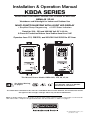
Installation & Operation Manual
KBDA SERIES
ADJUSTABLE FREQUENCY DRIVES FOR 3-PHASE AC MOTORS
NEMA-4X / IP-65
Washdown and Watertight for Indoor and Outdoor Use
MULTI-FUNCTION KEYPAD WITH 4-DIGIT LED DISPLAY
• Simplified Group Programming • 8 LED Status Indicators
Rated for 208 – 230 and 400/460 Volt 50* & 60 Hz
3-Phase AC Induction Motors from Subfractional thru 5 HP
Operates from 115, 208/230, and 400/460 Volt 50/60 Hz AC Line1
This Manual Covers Models KBDA-24D, 27D, 29, 45, 48
See Safety Warning,
on page 6.
2
3
*NOTE: THE DRIVE IS FACTORY SET FOR
60 Hz MOTORS. FOR 50 Hz MOTORS,
SEE FIGURE 16, ON PAGE 23.
The information contained in this manual is intended to be accurate. However, the manufacturer retains
the right to make changes in design which may not be included herein.
Notes: 1. Models KBDA-24D, 27D contain an AC line input voltage selection jumper. 2. All models are UL Listed for
USA and Canada. 3. Requires CE approved RFI filter. See AC Line Filters, in Table 1, on page 9.
© 2009 KB Electronics, Inc.
(see back cover)
TABLE OF CONTENTS
Section
Page
1 Quick-Start Instructions . . . . . . . . . . . . . . . . . . . . . . . . . . . . . . . . . . . . . . . . . . . . . . . . . . . . . . . . . . . . . . . 4
2 Safety Warning . . . . . . . . . . . . . . . . . . . . . . . . . . . . . . . . . . . . . . . . . . . . . . . . . . . . . . . . . . . . . . . . . . . . . . 6
3 Introduction . . . . . . . . . . . . . . . . . . . . . . . . . . . . . . . . . . . . . . . . . . . . . . . . . . . . . . . . . . . . . . . . . . . . . . . . . 7
4 Important Application Information . . . . . . . . . . . . . . . . . . . . . . . . . . . . . . . . . . . . . . . . . . . . . . . . . . . . . . 16
5 Mounting Instructions . . . . . . . . . . . . . . . . . . . . . . . . . . . . . . . . . . . . . . . . . . . . . . . . . . . . . . . . . . . . . . . . 17
6 Electrical Connections . . . . . . . . . . . . . . . . . . . . . . . . . . . . . . . . . . . . . . . . . . . . . . . . . . . . . . . . . . . . . . . 17
7 AC Line Input Voltage Selection (Jumper J1 (Models KBDA-24D, 27D Only)) . . . . . . . . . . . . . . . . . . . . 20
8 Recommended High Voltage Dielectric Withstand Testing (Hi-Pot Testing) . . . . . . . . . . . . . . . . . . . . . . 20
9 Drive Operation . . . . . . . . . . . . . . . . . . . . . . . . . . . . . . . . . . . . . . . . . . . . . . . . . . . . . . . . . . . . . . . . . . . . . 21
10 Programmable Function Summary List . . . . . . . . . . . . . . . . . . . . . . . . . . . . . . . . . . . . . . . . . . . . . . . . . . 31
11 Diagnostic LEDs . . . . . . . . . . . . . . . . . . . . . . . . . . . . . . . . . . . . . . . . . . . . . . . . . . . . . . . . . . . . . . . . . . . . 41
Appendix A – Optional IODA Input/Output Multi-Function Board . . . . . . . . . . . . . . . . . . . . . . . . . . . . . . . . . 42
Limited Warranty . . . . . . . . . . . . . . . . . . . . . . . . . . . . . . . . . . . . . . . . . . . . . . . . . . . . . . . . . . . . . . . . . . . . . . . 56
Table
Page
1 Optional Accessories . . . . . . . . . . . . . . . . . . . . . . . . . . . . . . . . . . . . . . . . . . . . . . . . . . . . . . . . . . . . . . . . . 9
2 General Performance Specifications . . . . . . . . . . . . . . . . . . . . . . . . . . . . . . . . . . . . . . . . . . . . . . . . . . . . . 9
3 Electrical Ratings . . . . . . . . . . . . . . . . . . . . . . . . . . . . . . . . . . . . . . . . . . . . . . . . . . . . . . . . . . . . . . . . . . . 10
4 Drive Terminal Block Wire and Tightening Torque Specifications . . . . . . . . . . . . . . . . . . . . . . . . . . . . . . 18
5 Multi-Function Output Relay “Run” and “Fault” Operating Modes . . . . . . . . . . . . . . . . . . . . . . . . . . . . . 19
6 Keypad Description . . . . . . . . . . . . . . . . . . . . . . . . . . . . . . . . . . . . . . . . . . . . . . . . . . . . . . . . . . . . . . . . . 22
7 Digital Readout Codes . . . . . . . . . . . . . . . . . . . . . . . . . . . . . . . . . . . . . . . . . . . . . . . . . . . . . . . . . . . . . . . 30
8 Model Software Revision Codes . . . . . . . . . . . . . . . . . . . . . . . . . . . . . . . . . . . . . . . . . . . . . . . . . . . . . . . 40
9 LED Descriptions . . . . . . . . . . . . . . . . . . . . . . . . . . . . . . . . . . . . . . . . . . . . . . . . . . . . . . . . . . . . . . . . . . . 41
10 IODA Status Indicator LED . . . . . . . . . . . . . . . . . . . . . . . . . . . . . . . . . . . . . . . . . . . . . . . . . . . . . . . . . . . . 42
11 IODA Terminal Block TB1 Wire and Tightening Torque Specifications . . . . . . . . . . . . . . . . . . . . . . . . . . 43
12 IODA Functions and Features . . . . . . . . . . . . . . . . . . . . . . . . . . . . . . . . . . . . . . . . . . . . . . . . . . . . . . . . . 44
13 Preset Frequency Selection . . . . . . . . . . . . . . . . . . . . . . . . . . . . . . . . . . . . . . . . . . . . . . . . . . . . . . . . . . . 45
14 Analog Input 1 Electrical Ratings . . . . . . . . . . . . . . . . . . . . . . . . . . . . . . . . . . . . . . . . . . . . . . . . . . . . . . . 50
15 Analog Input 2 Electrical Ratings . . . . . . . . . . . . . . . . . . . . . . . . . . . . . . . . . . . . . . . . . . . . . . . . . . . . . . . 50
16 Analog Outputs 1 and 2 Electrical Ratings . . . . . . . . . . . . . . . . . . . . . . . . . . . . . . . . . . . . . . . . . . . . . . . 51
17 Multi-Function Open Collector Outputs Electrical Ratings . . . . . . . . . . . . . . . . . . . . . . . . . . . . . . . . . . . 54
Figure
Page
1 Quick-Start Connection Diagram . . . . . . . . . . . . . . . . . . . . . . . . . . . . . . . . . . . . . . . . . . . . . . . . . . . . . . . . 4
2 Keypad Layout with Main Speed Potentiometer . . . . . . . . . . . . . . . . . . . . . . . . . . . . . . . . . . . . . . . . . . . 10
3 Model KBDA-24D Drive Layout . . . . . . . . . . . . . . . . . . . . . . . . . . . . . . . . . . . . . . . . . . . . . . . . . . . . . . . . 11
4 Model KBDA-27D Drive Layout . . . . . . . . . . . . . . . . . . . . . . . . . . . . . . . . . . . . . . . . . . . . . . . . . . . . . . . . 12
5 Models KBDA-29, 45, 48 Drive Layout . . . . . . . . . . . . . . . . . . . . . . . . . . . . . . . . . . . . . . . . . . . . . . . . . . 13
6 Model KBDA-24D Mechanical Specifications . . . . . . . . . . . . . . . . . . . . . . . . . . . . . . . . . . . . . . . . . . . . . 14
7 Models KBDA-27D, 29, 45, 48 Mechanical Specifications . . . . . . . . . . . . . . . . . . . . . . . . . . . . . . . . . . . 15
8 Maximum Allowed Motor Torque vs. Speed . . . . . . . . . . . . . . . . . . . . . . . . . . . . . . . . . . . . . . . . . . . . . . 16
9 Open Ventilated Motor with External Fan Cooling . . . . . . . . . . . . . . . . . . . . . . . . . . . . . . . . . . . . . . . . . . 16
10 Models KBDA-24D, 27D AC Line Input, Motor, and Ground Connections . . . . . . . . . . . . . . . . . . . . . . . 18
11 Models KBDA-29, 45, 48 AC Line Input, Motor, and Ground Connections . . . . . . . . . . . . . . . . . . . . . . 19
12 Multi-Function Output Relay Contacts . . . . . . . . . . . . . . . . . . . . . . . . . . . . . . . . . . . . . . . . . . . . . . . . . . . 19
13 Model KBDA-24D AC Line Input Voltage Selection (Jumper J1) . . . . . . . . . . . . . . . . . . . . . . . . . . . . . . . 20
14 Model KBDA-27D AC Line Input Voltage Selection (Jumper J1) . . . . . . . . . . . . . . . . . . . . . . . . . . . . . . . 20
15 Typical Hi-Pot Test Setup . . . . . . . . . . . . . . . . . . . . . . . . . . . . . . . . . . . . . . . . . . . . . . . . . . . . . . . . . . . . . 21
16 Flow Chart to Program the Drive for 50 Hz Motors . . . . . . . . . . . . . . . . . . . . . . . . . . . . . . . . . . . . . . . . . 23
17 Flow Chart to Program Motor Current from 6.7 Amps to 5.5 Amps . . . . . . . . . . . . . . . . . . . . . . . . . . . . 24
18 Flow Chart to Change Set Frequency from 5.00 Hz to 43.21 Hz . . . . . . . . . . . . . . . . . . . . . . . . . . . . . . 25
19 Flow Chart to Program Accel Time from 1.5 Seconds to 120 Seconds . . . . . . . . . . . . . . . . . . . . . . . . . 26
ii
20
21
22
23
24
25
26
27
28
29
30
31
32
33
34
35
36
37
38
39
Flow Chart to Program the Drive to Display Motor RPM . . . . . . . . . . . . . . . . . . . . . . . . . . . . . . . . . . . . . 27
Flow Chart to Program the Drive to Display Custom Units “012.0” . . . . . . . . . . . . . . . . . . . . . . . . . . . . 28
Flow Chart Showing Motor Current, Motor Voltage, and Bus Voltage added to the Basic Display . . . . 29
Function No. Description . . . . . . . . . . . . . . . . . . . . . . . . . . . . . . . . . . . . . . . . . . . . . . . . . . . . . . . . . . . . . 31
IODA Layout (All Models) . . . . . . . . . . . . . . . . . . . . . . . . . . . . . . . . . . . . . . . . . . . . . . . . . . . . . . . . . . . . . 43
IODA Terminal Block TB1 Layout . . . . . . . . . . . . . . . . . . . . . . . . . . . . . . . . . . . . . . . . . . . . . . . . . . . . . . . 43
Preset Frequency Selection Switch or Contact Connections and Function Settings . . . . . . . . . . . . . . . 45
Up/Down Frequency Control Switch or Contact Connections and Function Settings . . . . . . . . . . . . . . 46
Accel/Decel 2 Switch or Contact Connection and Function Settings . . . . . . . . . . . . . . . . . . . . . . . . . . . 46
Forward/Stop-Reverse/Stop Switch or Contact Connections and Function Settings . . . . . . . . . . . . . . 47
External Fault Auxiliary Equipment Switch or Contact Connection and Function Setting . . . . . . . . . . . 47
Reset Switch or Contact Connection and Function Setting . . . . . . . . . . . . . . . . . . . . . . . . . . . . . . . . . . 47
2-Wire Start/Stop Switch or Contact Connection and Function Settings . . . . . . . . . . . . . . . . . . . . . . . . 48
3-Wire Start/Stop Switch or Contact Connection and Function Settings . . . . . . . . . . . . . . . . . . . . . . . .49
Analog Input 1 Signal Voltage Following Connection and Function Settings . . . . . . . . . . . . . . . . . . . . . 49
Analog Input 2 Signal Current Following Connection and Function Settings . . . . . . . . . . . . . . . . . . . . . 50
Analog Outputs 1 and 2 Connections and Function Settings . . . . . . . . . . . . . . . . . . . . . . . . . . . . . . . . . 51
Bidirectional Motor Operation Main Speed Potentiometer Connection and Function Setting . . . . . . . . 52
Multi-Function Output Relay Contacts Connections and Function Settings . . . . . . . . . . . . . . . . . . . . . . 53
Multi-Function Open Collector Connections and Function Settings . . . . . . . . . . . . . . . . . . . . . . . . . . . . 54
Items Included In this Package:
KBDA Adjustable Frequency Drive, KBDA Series Installation and Operation Manual, CE Approved Product
Information Card, Warranty Registration Card, and Mounting Template.
UL Notice
230 VAC Controls
Suitable For Use On A Circuit Capable Of Delivering Not More Than 5 kA RMS Symmetrical Amperes,
230 Volts Maximum.
Use Copper Conductors Rated 75 ºC.
Suitable for Operation in a Maximum Surrounding Air Temperature of 40 ºC.
460 VAC Controls
Suitable For Use On A Circuit Capable Of Delivering Not More Than 5 kA RMS Symmetrical Amperes,
460 Volts Maximum.
Use Copper Conductors Rated 75 ºC.
Suitable for Operation in a Maximum Surrounding Air Temperature of 40 ºC.
iii
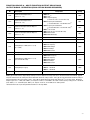
IMPORTANT APPLICATION INFORMATION
1.
50 Hz Motors – This drive has been factory programmed to operate 60 Hz motors. For 50 Hz motor
operation, set Function No. 0.00 to “0001”. See Figure 16, on page 23.
2.
Motor Current Setting – The motor current for all drive models is factory set to the maximum drive rating, as shown in Table 3, on page 10. In order for the motor overload protection to operate properly, the
drive must be reprogrammed to the actual motor nameplate current. Use Function No. 0.01 to enter the
motor nameplate current. See Figure 17, on page 24.
a. Model KBDA-27D – Has a maximum current rating of 6.7 Amps (2 HP (1.5 kW)) when used with a
208 – 230 Volt 50/60 Hz AC line input (factory setting of motor current and AC line input voltage).
When used with 115 Volt 50/60 Hz AC line input (Jumper J1 installed in the “115V” position), the
maximum rating of the drive is 5.5 Amps (11⁄2 HP (1.13 kW)). Be sure to reprogram Motor Current
(Function No. 0.01) to the actual motor nameplate current rating (not to exceed 5.5 Amps).
b. Model KBDA-29 – Has a maximum rating of 9.0 Amps (3 HP (2.25 kW)) when used with a 208 – 230
Volt 50/60 Hz 3-phase AC line input. When used with a 208 – 230 Volt 50/60 Hz single-phase AC
line input, the maximum rating of the drive is 6.7 Amps (2 HP (1.5 kW)). Be sure to reprogram Motor
Current (Function No. 0.01) to the actual motor nameplate current rating (not to exceed 6.7 Amps).
1
QUICK-START INSTRUCTIONS
Important: You must read these simplified instructions before proceeding. These instructions are to
be used as a reference only and are not intended to replace the details provided herein. You must
read the Safety Warning on, page 6, before proceeding.
Note: This drive contains bus capacitors, which must be reconditioned if the drive has been in storage for over 1 year. To recondition the bus capacitors, apply the AC line, with the drive in the Stop
Mode, for a minimum of 30 minutes.
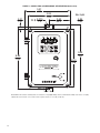
See Figure 1. Also see Section 4 - Important Application Information, on page 16.
WARNING! HIGH VOLTAGE – Disconnect main power before making connections
to the drive.
FIGURE 1 – QUICK-START CONNECTION DIAGRAM1
TB1
U
V
W
MOTOR
Motor
Ground (Earth):
see Section 6.2, on page 19.
3-Phase
AC Induction Motor:
see Section 6.3, on page 19.
Notes: 1. Layout of Models KBDA-24D, 27D
vary slightly. 2. 50/60 Hz AC line input.
4
L1
L2
AC LINE
L3
208/230 Volt, Single Phase 2
(Terminals "L1", "L2")
(Models KBDA-24D, 27D, 29):
see Section 6.1, on page 18.
208/230, 400/460 Volt, 3-Phase 2
(Terminals "L1", "L2", "L3")
(Models KBDA-29, 45, 48):
see Section 6.1, on page 18.
Ground (Earth):
see Section 6.2, on page 19.
1.1
AC LINE INPUT CONNECTION – Connect the AC line input to Terminal Block TB1. See Section
6.1, on page 18.
Application Note – If operation with a Ground-Fault Circuit-Interrupter (GFCI) is required,
see Function No. 0.04, on page 32.
Note: The rated AC line voltage of the drive must match the actual AC line input voltage. On
Models KBDA-24D, 27D, the setting of Jumper J1 must match the AC line input voltage.
Model KBDA-24D – Terminals “L1”, “L2” – Designed for single-phase AC line input only. Rated
for 208/230 Volt AC line input with Jumper J1 set to the “230V” position (factory setting) and rated
for 115 Volt AC line input with Jumper J1 set to the “115V” position. See Figure 10, on page 18.
Note: 230 Volts AC will be applied to the motor with 115 Volt AC line input.
Model KBDA-27D – Terminals “L1”, “L2” – Designed for single-phase AC line input only. Rated
for 208/230 Volt AC line input with Jumper J1 set to the “230V” position (factory setting) and
rated for 115 Volt AC line input with Jumper J1 set to the “115V” position. Rated for 11⁄2 HP
maximum with 115 Volt AC line input and 2 HP maximum with 208/230 Volt AC line input.
See Figure 10, on page 18.
Note: 230 Volts AC will be applied to the motor with 115 Volt AC line input.
Model KBDA-29 – Terminals “L1”, “L2”, “L3” – Designed for single-phase or 3-phase AC line
input. Rated for 208/230 Volt AC line input only. Rated for 2 HP maximum with single-phase AC
line input (Terminals “L1”, “L2”) and 3 HP maximum with 3-phase AC line input (Terminals “L1”,
“L2”, “L3”). See Figure 11, on page 19.
Models KBDA-45, 48 – Terminals “L1”, “L2”, “L3” – Designed for 3-phase AC line input only.
Rated for 400/460 Volt AC line input only. See Figure 11, on page 19.
1.2
AC LINE FUSING – It is recommended that a fuse(s) or circuit breaker be installed in the AC line.
Fuse each conductor that is not at ground potential. For the recommended fuse size, see Table 3,
on page 10. Also see Section 6.1, on page 18.
1.3
GROUND CONNECTION – Connect the ground wire (earth) to the Ground Screw, as shown in
Figures 10 and 11, on pages 18 and 19. Be sure the motor is also properly grounded. Two Ground
Screws are provided.
1.4
MOTOR CONNECTION – Connect the motor to Terminal Block TB1 Terminals “U”, “V”, “W”, as
shown in Figures 10 and 11, on pages 18 and 19. Be sure the motor is properly grounded. Motor
cable length should not exceed 100 ft. (30 m) – special reactors may be required – consult our
Sales Department. See Section 6.3, on page 19.
1.5
60 Hz and 50 Hz MOTOR OPERATION – The drive is factory set for 60 Hz motors (Function No.
0.00 set to “0000”). For 50 Hz motors, set Function No. 0.00 to “0001”, as shown in Figure 16, on
page 23. For other motor frequencies, set Function No. 0.00 to “0002”.
1.6
JUMPER J1 SETTING (Models KBDA-24D, 27D Only) – Jumper J1 has been factory set for 230
Volt AC line input (installed in the “230V” position). For 115 Volt AC line input, set Jumper J1 to
the “115V” position. See Section 7, on page 20.
1.7
MOTOR OVERLOAD PROTECTION – Function No. 0.01 must be set to the motor nameplate
current for proper operation of the I2t Motor Overload Protection. See Figure 17, on page 24.
5
2
SAFETY WARNING
Definition of Safety Warning Symbols
Electrical Hazard Warning Symbol – Failure to observe this warning could result in electrical
shock or electrocution.
Operational Hazard Warning Symbol – Failure to observe this warning could result in serious
injury or death.
This product should be installed and serviced by a qualified technician, electrician, or
electrical maintenance person familiar with its operation and the hazards involved. Proper
installation, which includes electrical connections, fusing or other current protection, and grounding,
can reduce the chance of electrical shocks, and/or fires, in this product or products used with this
product, such as electric motors, switches, coils, solenoids, and/or relays. Do not use this drive in
an explosion-proof application. Eye protection must be worn and insulated adjustment tools must
be used when working with drive under power. This product is constructed of materials (plastics,
metals, carbon, silicon, etc.) which may be a potential hazard. Proper shielding, grounding, and filtering of this product can reduce the emission of radio frequency interference (RFI) which may
adversely affect sensitive electronic equipment. It is the responsibility of the equipment manufacturer and individual installer to supply this Safety Warning to the ultimate end user of this product. (SW
1/2006)
The drive contains electronic Start/Stop circuits, which can be used to start and stop the drive.
However, these circuits are never to be used as safety disconnects since they are not fail-safe. Use
only the AC line for this purpose.
Be sure to read and follow all instructions carefully. Fire and/or electrocution can result due to
improper use of this product.
This product complies with all CE directives pertinent at the time of manufacture. Contact our
Sales Department for Declaration of Conformity. Installation of a CE approved RFI filter is
required. See Table 1, on page 9. For some applications, additional shielded cables, filters, and chokes
may be required along with a signal isolator (IODA Input/Output Multi-Function Board (Part No. 9668)).
6
3
INTRODUCTION
Thank you for purchasing the KBDA Adjustable Frequency Drive. KB Electronics, Inc. is committed to
providing total customer satisfaction by producing quality products that are easy to install and operate.
The KBDA Adjustable Frequency Drives are variable speed controls housed in a rugged NEMA-4X /
IP-65 washdown and watertight die-cast aluminum enclosure. They are designed to operate 208 – 230
and 400/460 Volt 50 & 60 Hz 3-phase AC induction motors from subfractional thru 5 HP. The sine wave
coded Pulse Width Modulated (PWM) output provides high motor efficiency and low noise. Adjustable
Linear Acceleration and Deceleration make the drive suitable for soft-start applications.
Due to its user-friendly design, the KBDA is easy to install and operate. Setting the drive to specific
applications is accomplished using the Multi-Function Keypad, which provides easy operation and
programming of the drive. To facilitate programming, all similar functions are presented in common
groups. For more advanced programming, PC based Drive-Link™ software is available.
The 4-Digit LED Display provides readout of drive operating parameters and programming functions
and displays Output Frequency, Motor RPM, Output Current, Output Voltage, Bus Voltage, Function
Codes and Values, Fault Codes, and Custom Units. In addition to operating the drive, the MultiFunction Keypad is used to change drive operating parameters, reprogram functions, and change the
display output. The LEDs provide indication of the drive’s status and operating mode (Hz, PGM,
LCL/REM, STOP, FWD, REV, OL, JOG/REM).
The optional IODA Input/Output Multi-Function Board provides a variety of functions, which include preset frequency, up/down frequency control, signal isolation, isolated output voltage for controlling auxiliary devices, open collector outputs, and output relay contacts. See Appendix A, on pages 42 – 54. See
Function Groups 7 – 9, on pages 36 – 38.
Main Features – Adjustable RMS Current Limit and I2t Motor Overload Protection.* Flux Vector
Compensation with Static Auto-Tune and Boost provides high torque and excellent load regulation over
a wide speed range. Power Start™ delivers over 200% motor torque to ensure startup of high frictional
loads. Programmable Injection Braking provides rapid motor stop. Electronic Inrush Current Limit
(EICL™) eliminates harmful AC line inrush current, which allows the drive to be line switched. A MultiFunction Output Relay is provided, which can be used to turn on or off equipment or to signal a warning if the drive is put into various modes of operation. Models KBDA-29**, 45, 48 also contain AC Line
Phase Loss Detection. The drive is suitable for machine or variable torque (HVAC) applications.
*UL approved as an electronic overload protector for motors.
**When used on 3-phase AC line input set for 7.0 Amps or higher (3 HP (2.25 kW)).
Standard Front Panel Features – 4-Digit LED Display, Multi-Function Keypad, Status Indicator LEDs,
and a Main Speed Potentiometer.
Optional Accessories – On/Off AC Line Switch, Class “A” AC Line Filter, IODA Input/Output MultiFunction Board, Programming Kit, DIAC Modbus Communication Module, and Liquidtight Fittings. See
Table 1, on page 9.
3.1
STANDARD FEATURES
• Industrial Duty Die-Cast Aluminum Enclosure with Hinged Cover – Available in dark gray
finish or FDA approved white finish.
• Multi-Function Keypad – The keys are used to operate the drive, change operating parameters, reprogram functions, and change the display output (Run/Stop, Forward/Reverse, Up,
Down, Shift/Reset, Jog-Local/Remote, Program/Display, Read/Enter).
• 4-Digit LED Display – Provides readout of drive operating parameters and programming functions. Displays Output Frequency, Motor RPM, Output Current, Output Voltage, Bus Voltage,
Function No. Codes and Values, Fault Codes, and Custom Units.
7
• LED Status Indicators – The LEDs provide indication of the drive’s status and operating mode
(Hz, PGM, LCL/REM, STOP, FWD, REV, OL, JOG/REM).
• Multi-Function Output Relay Contacts – Can be used to turn on or off equipment or to signal
a warning if the drive is put into various modes of operation. (The optional IODA Input/Output
Multi-Function Board contains 9 digital and analog inputs, 4 digital and analog outputs, and 2
additional relay outputs.)
• Motor Current Selection – Programmable motor current allows the drive to be used on a wide
range of motor horsepower.
• Compatible with GFCIs. See Function No. 0.04, on page 32.
3.2
PERFORMANCE FEATURES
• Power Start™ – Provides more than 200% starting torque which ensures startup of high frictional loads.
• Programmable Flux Vector Compensation with Static Auto-Tune and Boost – Provides
excellent load regulation and dynamic response over a wide speed range.
• Speed Range – 60:1
3.3
PROTECTION FEATURES
• Motor Overload (I2t) with RMS Current Limit – Provides motor overload protection, which
prevents motor burnout and eliminates nuisance trips.*
• Electronic Inrush Current Limit (EICL™) – Eliminates harmful inrush AC line current during
startup.
• Short Circuit – Shuts down the drive if a short circuit occurs at the motor (phase-to-phase).
• AC Line Phase Loss Detection (Models KBDA-29**, 45, 48 only.)
• Decel Extend – Eliminates tripping due to bus overvoltage caused by rapid deceleration of
high inertial loads.
• Undervoltage and Overvoltage – Shuts down the drive if the AC line input voltage goes below
or above the operating range.
• MOV Input Transient Suppression.
• Microcontroller Self Monitoring and Auto-Reboot.
*UL approved as an electronic overload protector for motors.
**When used on 3-phase AC line input set for 7.0 Amps or higher (3 HP (2.25 kW)).
8
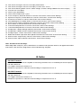
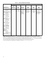
TABLE 1 – OPTIONAL ACCESSORIES
Accessory Part No.
Model
Model
Model
Model
Model
KBDA-24D KBDA-27D KBDA-29 KBDA-45 KBDA-48
Description
On/Off AC Line Switch – Disconnects the AC line. Mounts on the enclosure
cover and is supplied with a switch seal to maintain liquidtight integrity.
9482
9523
9532
9532
9532
Suffix
“S”
9507
9512
9479
9479
9479
Suffix
“NS”
9507
9512
9515
9515
9515
IODA Input/Output Multi-Function Board – Provides a variety of functions,
which include preset frequency, up/down frequency control, signal isolation,
isolated output voltage for controlling auxiliary devices, open collector outputs,
and output relay contacts. Mounts on the drive’s PC board with two snap-ins
(located on the bottom of the mounting base) and two screws (provided). All of
the IODA inputs and outputs are isolated from the AC line.
See Appendix A, on page 42.
9668
9668
9668
9668
9668
Programming Kit – Includes DownLoad Module™ (DLM) handheld programming device, which uploads and downloads drive programs, PC to DLM
serial and USB communication cables, DLM to inverter communication cable,
and PC Windows® based Drive-Link™ communication software.
9582
9582
9582
9582
9582
DIAC Modbus Communication Module – Allows direct communication
between drive and Modbus2 protocol.
9517
9517
9517
9517
9517
Liquidtight Fittings – Provide a liquidtight seal for wiring the drive. Kit
includes three 1/2” and one 3/4” liquidtight fittings.
9526
9526
9526
9526
9526
AC Line Filter1 – Provides Class A Industrial Standard RFI (EMI)
suppression. Installs onto the drive’s PC board with quick-connect
terminals.
Suffix “S” – Filter must be used with built-in On/Off AC Line Switch.
Suffix “NS” – Filter must be used without On/Off AC Line Switch.
Notes: 1. Complies with CE Council Directive 89/336/EEC Industrial Standard. 2. Other protocols available – contact our Sales Department.
TABLE 2 – GENERAL PERFORMANCE SPECIFICATIONS
Description
Specification
Factory Setting
115 Volt AC Line Input Voltage Operating Range (Volts AC)
115 (± 15%)
—
208/230 Volt AC Line Input Voltage Operating Range (Volts AC)
208 (-15%) / 230 (+15%)
—
400/460 Volt AC Line Input Voltage Operating Range (Volts AC)
380 (-15%) – 460 (+15%)
—
150
—
Maximum Load (% of Current Overload for 2 Minutes)
Switching Frequency (kHz)
Signal Following Input Voltage Range1 (Volts DC)
Output Frequency Resolution (Bits, Hz)
Minimum Operating Frequency at Motor (Hz)
8, 10, 12
8
0–5
—
10, .06
—
0.3
—
Acceleration Time (Seconds)
0.1 – 180.0
1.5
Deceleration Time (Seconds)
0.3 – 180.0
1.5
Speed Range (Ratio)
60:1
—
Speed Regulation (30:1 Speed Range, 0 – Full Load) (% Base Speed) 2
2.5
—
6
—
Undervoltage/Overvoltage Trip Points for 115 Volt AC Line Input (± 5%) (Volts AC)3
76 / 141
—
Undervoltage/Overvoltage Trip Points for 208/230 Volt AC Line Input (± 5%) (Volts AC)3
Undervoltage/Overvoltage Trip Points for 400/460 Volt AC Line Input (± 5%) (Volts AC)3
151 / 282
—
302 / 567
—
1, 0.5, 0.25
—
0 – 45 / 32 – 113
—
Overload Protector Trip Time for Stalled Motor (Seconds)
Run/Fault Output Relay Contact Rating (Amps at 30 Volts DC, 125 Volts AC, 250 Volts AC)
Operating Temperature Range (°C / °F)
Notes: 1. IODA option board required. 2. Dependent on motor performance. 3. Do not operate the drive outside the specified AC line input voltage
operating range.
9
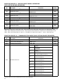
TABLE 3 – ELECTRICAL RATINGS
AC Line Input
Output
Fuse or
Circuit
Maximum
Continuous
Maximum Breaker
Voltage
Maximum Net Wt.
Part No.
Volts AC2 Phase Current
Range
Rating
Load Current3 Horsepower
(Gray / White 1) (50/60 Hz) (φ) (Amps AC) (Amps AC) (Volts AC) (RMS Amps/Phase) (HP (kW)) lbs kg
Model
KBDA-24D4
9536/9537
KBDA-27D4,5
9543/9544
KBDA-296,7
9545 /9546
115
1
16
20
208/230
1
10
15
115
1
22
208/230
1
15
1
3
208/230
0 – 230
3.6
1 (.75)
25
0 – 230
5.5
1 ⁄2 (1.13)
20
0 – 230
6.73
2 (1.5)
15
20
0 – 230
6.7
2 (1.5)
10.8
15
0 – 230
9.03
3 (2.25)
5.9 2.7
1
10.3 4.7
10.3 4.7
KBDA-457,8
9659/9660
400/460
3
5.3
10
0 – 400/460
4.6
3 (2.25)
10.3 4.7
KBDA-487,8
9661 /9662
400 /460
3
9.6
15
0 – 400/460
8.3
5 (3.75)
10.3 4.7
Notes: 1. White FDA approved finish. 2. Bold indicates factory setting of AC line input voltage for Models KBDA-24D, 27D. 3. Factory setting
of motor current (Function No. 0.01). 4. Models KBDA-24D, 27D contain an AC line input voltage selection jumper. 5. Model KBDA-27D is
rated 11⁄2 HP (1.13 kW) with 115 Volt AC line input and 2 HP (1.5 kW) with 208/230 Volt AC line input. 6. Model KBDA-29 is rated 2 HP
(1.5 kW) with single-phase AC line input and 3 HP (2.25 kW) with 3-phase AC line input. 7. Also contain AC Line Phase Loss Detection
(Model KBDA-29: when used on 3-phase AC line input set for 7.0 Amps or higher (3 HP (2.25 kW)). 8. Models KBDA-45, 48 are rated
0 – 400 Volts AC for 50 Hz motor operation and 0 – 460 Volts AC for 60 Hz motor operation.
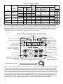
FIGURE 2 – KEYPAD LAYOUT WITH MAIN SPEED POTENTIOMETER
4-Digit Display
Drive is set for Reverse Direction.
Drive is in Stop Mode.
Drive is set for Forward Direction.
Indicates JOG-LCL/REM Key
is set for Local/Remote Signal
Operation.2
Drive is in Overload.
Drive is in Jog Operation
or Remote Signal Operation.1, 2
Drive is in Program Mode.
Drive Frequency displayed.3
Up Key: Increases Output Frequency,
Set Frequency, Function Number Value,
and Code setting.
Left Shift / Reset Key: Moves
the changeable digit or Resets
the drive after a fault has cleared.
Starts or Stops the drive.
Used to enter the Program Mode 4
and Display Mode.
Changes motor direction.
Displays or enters a Function Value
or Code Setting.
Down Key: Decreases Output Frequency,
Set Frequency, Function Number Value,
and Code setting.
Sets the drive to Jog Mode or
changes between Local (Keypad)
or Remote Signal Operation.1, 2
Potentiometer: Sets Drive Output Frequency. 5
Notes: 1. The JOG-LCL/REM Key is factory programmed to function as a Jog Key. When the JOG-LCL/REM Key is pressed, the “JOG/REM”
LED will illuminate and the display will show the Jog Frequency Setting (see Function No. 3.13, on page 34). 2. If the JOG-LCL/REM Key is
reprogrammed for Local (Keypad) and Remote Signal Operation (see Function No. 2.02, on page 34), the “LCL/REM” LED will illuminate.
Pressing the JOG-LCL/REM Key will toggle between Local (Keypad) and Remote Signal Operation. When Remote Signal Operation is selected, the “JOG/REM” LED will flash. The optional IODA (Part No. 9668) is required for remote signal operation. 3. The “Hz” LED will illuminate
when the display is set to show Output Frequency. 4. If the PROGRAM/DISPLAY Key is pressed while Set Frequency is displayed, the previously entered Function Number will be shown. If the PROGRAM/DISPLAY Key is pressed while Function Number is displayed, the Set
Frequency will be shown. When more than one display function is enabled, the PROGRAM/DISPLAY Key is used to toggle between displays,
as shown in Figure 22, on page 29. 5. To change the Keypad for Potentiometer Operation, set Function No. 2.00 to “0001”.
10
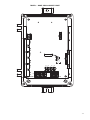
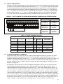
115V
J1
230V
TB2
CON1
NO COM NC
FIGURE 3 – MODEL KBDA-24D DRIVE LAYOUT
L1A
L1B
L2A
L2B
TB1
MOTOR
U
V
W
L1
L2
AC LINE
11
TB2
CON1
NO COM NC
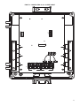
FIGURE 4 – MODEL KBDA-27D DRIVE LAYOUT
J1
115V
230V
L2B
L1B
L2A
L1A
TB1
U
12
V
MOTOR
W
L2
L3
AC LINE
TB2
CON1
NO COM NC
FIGURE 5 – MODELS KBDA-29, 45, 48 DRIVE LAYOUT
L1B
L1A
L2B
L2A
L3B
L3A
TB1
U
V
MOTOR
W
L1
L2
AC LINE
L3
13
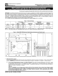
FIGURE 6 – MODEL KBDA-24D MECHANICAL SPECIFICATIONS (Inches/mm)
5.51
140
5.06
129
0.31
7.97
2X ø
4*
0.275
7.0
Max. Depth:
5.86
149
2.53
64.4
1*
9.53
242
8.85
225
8.20
208
2*
3*
Model KBDA-24D contains mounting holes for standard 1/2” liquidtight fittings. The recommended mounting screw size is 1/4” (M6).
*Tighten the four enclosure cover screws, in the sequence shown, to 12 in-lbs (14 kg-cm).
14
FIGURE 7 – MODELS KBDA-27D, 29, 45, 48 MECHANICAL SPECIFICATIONS (Inches/mm)
4X ø
0.275
7.0
2X
4*
1.00
25.4
2X
0.30
7.37
1*
8.50
216
9.25
235
9.80
249
2*
3*
7.15
181
7.55
192
Max. Depth: 7.25
184
Models KBDA-27D, 29, 45, 48 contain two mounting holes for standard 1/2” liquidtight fittings and one mounting hole for
standard 3/4” liquidtight fitting. The recommended mounting screw size is 1/4” (M6).
*Tighten the four enclosure cover screws, in the sequence shown, to 12 in-lbs (14 kg-cm).
15
4
IMPORTANT APPLICATION INFORMATION
4.1
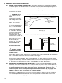
MOTOR WITH EXTERNAL FAN COOLING – Most totally enclosed fan-cooled (TEFC) and open
ventilated 3-phase AC induction motors will overheat if used beyond a limited speed range at full
torque. Therefore, it is necessary to reduce motor load as speed is decreased.
Note: Some fan-cooled motors can be used over a wider speed range. Consult the motor
manufacturer for details.
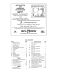
FIGURE 8 – MAXIMUM ALLOWED MOTOR TORQUE VS. SPEED
100
Inverter Duty
and TENV Motors
80
Maximum Allowed
Motor Torque (%)
WARNING! Some
motors have low
speed characteristics,
which cause overheating
and winding failure under
light load or no load conditions. If the motor is
operated in this manner
for an extended period of
time, it is recommended
that the unloaded motor
current be checked from
2 – 15 Hz (60 – 450 RPM)
to ensure motor current
does not exceed the
nameplate rating. If the
motor current exceeds the
nameplate rating, the
Boost value may have to
be decreased (see
Function No. 3.11). Do
not use motor if the
motor current exceeds
the nameplate rating.
Fan Cooled
TEFC and Open Ventilated
Motors
60
40
20
0
0
10
20
30
40
50
60
70
80
90
100
Motor Speed (%)
FIGURE 9 – OPEN VENTILATED MOTOR WITH EXTERNAL FAN COOLING
Airflow
Open Ventilated Motor
Fan or Blower
(100 CFM per HP Min.)
It is recommended
that the drive be
used with Inverter Duty
or TENV motors.
Inverter duty and most totally enclosed non-ventilated (TENV) motors can provide full rated torque
over an extended speed range without overheating. See Figure 8.
If external fan cooling is provided, open ventilated motors can also achieve an extended speed
range at full rated torque. A box fan or blower with a minimum of 100 CFM per HP is recommended. Mount the fan or blower so the motor is surrounded by the airflow. See Figure 9.
4.2
ELECTRONIC MOTOR OVERLOAD PROTECTION – The drive contains Modified I2t Overload
Protection.* Part of this function consists of a Current Limit (CL) circuit, which limits the drive current to a preset level of 160% of the Motor Nameplate Rated Current setting. The factory setting
for motor nameplate current is the drive rated current, which must be set to the actual
motor nameplate current (see Important Application Information (Item 2), on page 4). See
Table 3, on page 10. Also see Function No. 0.01, on page 32.
Standard I2t is undesirable because it causes nuisance tripping. It allows a very high motor current to develop and will turn the drive off after a short period of time. KB’s RMS Current Limit
Circuit avoids this nuisance tripping while providing maximum motor protection.
16
If the motor is overloaded to 120% of the Motor Nameplate Rated Current setting, the I2t
Timer starts. If the motor continues to be overloaded at the 120% level, the timer will shut
down the drive after 30 minutes. If the motor is overloaded to 160% of full load, the drive will
trip in 6 seconds.
*UL approved as an overload protector for motors.
5
MOUNTING INSTRUCTIONS
It is recommended that the drive be mounted vertically on a flat surface with adequate ventilation.
Leave enough room below the drive to allow for AC line, motor connections, and any other connections
that are required. Although the drive is designed for outdoor and washdown use, care should be taken
to avoid extreme hazardous locations where physical damage can occur. When mounting the drive in an
enclosure, the enclosure should be large enough to allow for proper heat dissipation so that the ambient temperature does not exceed 45°C (113 °F) at full rating. The recommended mounting screw size is
1/4 inch (M6). See Figures 6 and 7, on pages 14 and 15.
WARNING! Do not use this drive in an explosion-proof application.
Be sure the drive is securely mounted.
6
ELECTRICAL CONNECTIONS
WARNING! HIGH VOLTAGE – Read Safety Warning, on page 6, before using the drive.
Disconnect main power before making connections to the drive. To avoid electric shock,
be sure to properly ground the drive.
Application Note: To avoid erratic operation, do not bundle the AC line and motor wires with each
other or with wires from signal following, start/stop contacts, or any other signal wires. Also, do not
bundle motor wires from multiple drives in the same conduit. Use shielded cables on all signal wires
over 12” (30 cm). The shield should be earth grounded on the drive side only. Connect the drive in
accordance with the National Electrical Code requirements and other local codes that may apply.
Be sure to properly fuse each AC line conductor that is not at ground potential. Do not fuse neutral
or grounded conductors. A separate AC line switch or contactor must be installed as a disconnect
so that each ungrounded conductor is opened. For fuse or circuit breaker selection, see Table 3, on
page 10. Also see Section 6.1, on page 18.
To maintain the watertight integrity of the drive, be sure to use suitable liquidtight fittings and wires
that are appropriate for the application. Model KBDA-24D contains mounting holes for standard 1/2”
liquidtight fittings (not supplied) (two liquidtight plugs are provided, if only one knockout is used).
Models KBDA-27D, 29, 45, 48 contain two mounting holes for standard 1/2” liquidtight fittings (not
supplied) and one mounting hole for standard 3/4” liquidtight fitting (not supplied) (two liquidtight
plugs are provided, if only one knockout is used). The Liquidtight Fittings Kit (Part No. 9526) is available for all models (see Table 1, on page 9).
The drive is designed with a hinged case so that, when the front cover is open, all wires stay intact.
To open the cover, the four screws must be loosened so they are no longer engaged in the case bottom. After mounting the drive and all electrical connections are complete, close the cover making
sure that the wires do not get caught or crimped as the cover is closed. Tighten the four screws so
that the gasket is slightly compressed. The recommended tightening torque is 12 in-lbs (14 kg-cm).
See Figures 6 and 7, on pages 14 and 15, for the tightening sequence. Do not overtighten.
17
TABLE 4 – DRIVE TERMINAL BLOCK WIRE AND TIGHTENING TORQUE SPECIFICATIONS
Maximum Wire Size (Cu) Recommended Tightening Torque
Terminal Block
Description
Model
AWG
mm2
in-lbs
TB1
AC Line Input and Motor
Connections
KBDA-24D
12
3.3
7
8
KBDA-27D, 29, 45, 48
12
3.3
12
14
TB2
Run/Fault Output Relay Contacts
All
16
1.3
3.5
4
6.1
kg-cm
AC LINE INPUT CONNECTION (see Warning, on page 17) – Connect the AC line input to
Terminal Block TB1. See Electrical Ratings, Table 3, on page 10.
Application Note: If operation with a Ground-Fault Circuit-Interrupter (GFCI) is required, see
Function No. 0.04, on page 32.
Note: The rated AC line voltage of the drive must match the actual AC line input voltage. On
Models KBDA-24D, 27D, the setting of Jumper J1 must match the AC line input voltage.
AC Line Fusing – The drive does not contain line fuses. Most electrical codes require that each
ungrounded conductor contain circuit protection. Do not fuse neutral or ground connections.
It is recommended to install a fuse (Littelfuse 326, Buss ABC, or equivalent) or a circuit breaker
(Square D QOU or equivalent) in series with each ungrounded conductor. Do not fuse motor
leads. For the recommended fuse size, see Table 3, on page 10.
Connect the drive in accordance with the National Electrical Code requirements and other local
codes that may apply to the application.
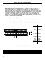
Model KBDA-24D –
Terminals “L1”, “L2” –
Designed for single-phase
AC line input only. Rated for
208/230 Volt AC line input
with Jumper J1 set to the
“230V” position (factory setting) and rated for 115 Volt
AC line input with Jumper
J1 set to the “115V” position. See Figure 10.
Note: 230 Volts AC will be
applied to the motor with
115 Volt AC line input.
FIGURE 10 – MODELS KBDA- 24D, 27D*
AC LINE INPUT, MOTOR, AND GROUND CONNECTIONS
MOTOR
AC LINE
TB1
U
Ground
(Earth)
V
Motor
W
L1
L2
115, 208/230 Volt
Single-Phase
AC Line Input
Ground
(Earth)
*Model KBDA-27D is rated for 11⁄2 HP maximum with 115 Volt AC line input and 2 HP
maximum with 208/230 Volt AC line input.
Model KBDA-27D – Terminals “L1”, “L2” – Designed for single-phase AC line input only. Rated
for 208/230 Volt AC line input with Jumper J1 set to the “230V” position (factory setting) and rated
for 115 Volt AC line input with Jumper J1 set to the “115V” position. Rated for 11⁄2 HP maximum
with 115 Volt AC line input and 2 HP maximum with 208/230 Volt AC line input. See Figure 10.
Note: 230 Volts AC will be applied to the motor with 115 Volt AC line input.
Model KBDA-29 – Terminals “L1”, “L2”, “L3” – Designed for single-phase or 3-phase AC line
input. Rated for 208/230 Volt AC line input only. Rated for 2 HP maximum with single-phase AC
line input (Terminals “L1”, “L2”) and 3 HP maximum with 3-phase AC line input (Terminals “L1”,
“L2”, “L3”). See Figure 11, on page 19.
Models KBDA-45, 48 – Terminals “L1”, “L2”, “L3” – Designed for 3-phase AC line input only.
Rated for 400/460 Volt AC line input only. See Figure 11, on page 19.
18
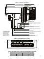
FIGURE 11 – MODELS KBDA-291, 452, 482
AC LINE INPUT, MOTOR, AND GROUND CONNECTIONS
MOTOR
Model KBDA-29 Only
Wire the single-phase AC line input
to Terminals "L1" & "L2", as shown below.
AC LINE
TB1
U
Ground
(Earth)
V
W
L1
L2
L3
L1
208/230, 400/460 Volt
3-Phase, 50/60 Hz
AC Line Input
Motor
L3
L2
208/230 Volt
Single-Phase, 50/60 Hz
AC Line Input
Ground
(Earth)
Notes: 1. Model KBDA-29 is rated for 2 HP maximum with single-phase AC line input and 3 HP maximum with 3-phase AC line input.
2. Models KBDA-29, 45, 48 contain AC Line Phase Loss Detection. (Model KBDA-29: when used on 3-phase AC line input set for 7.0 Amps
or higher (3 HP (2.25 kW)).
6.2
GROUND CONNECTION – Connect the ground wire (earth) to any available green Ground Screw.
The two Ground Screws are located near Terminal Block TB1. Be sure the motor is also properly
grounded. See Figure 10, on page 18, and Figure 11, above.
6.3
MOTOR CONNECTION – Connect the motor to Terminal Block TB1 Terminals “U”, “V”, “W”. See
Figure 10, on page 18, and Figure 11, above. Be sure the motor is properly grounded. Motor cable
length should not exceed 100 ft. (30 m) – special reactors may be required – consult our Sales
Department. Be sure Function No. 0.01 is set to the corresponding Motor Nameplate Current.
Note: If the motor does not rotate in the desired direction, either: 1. Reverse any two motor leads
(with AC line disconnected and motor stopped). or 2. Use the FWD/REV Key. or 3. Use Function
No. 1.02 to reprogram the forward and reverse direction.
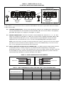
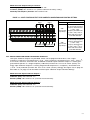
MULTI-FUNCTION OUTPUT RELAY CONNECTION – The Multi-Function Output Relay Contacts
are located at TB2, as shown in Figure 12. The Multi-Function Output Relay is factory programmed to function as a “Run” relay (Function No. 5.00 set to “0000”). When the drive is put into
the Run Mode, the relay contacts will change state (the Normally Open (N.O.) contact will close
and the Normally Closed (N.C.) contact will open). See Table 5.
FIGURE 12 – MULTI-FUNCTION OUTPUT RELAY CONTACTS
Output Contacts
Relay Common
Normally Open
KBDA-24D
Normally Closed
NO COM NC
KBDA-27D, 29, 45, 48
Normally Closed
NO COM NC
6.4
TB2
Relay Common
Output Contacts
Normally Open
TB2
TABLE 5 – MULTI-FUNCTION OUTPUT RELAY “RUN” AND “FAULT” RELAY OPERATING MODES
Function 5.00 Set to “0000”
“Run” Relay Mode
Function 5.00 Set to “0001”
“Fault” Relay Mode
Drive Operating Condition
N.O. Contact
N.C. Contact
N.O. Contact
N.C. Contact
Power Off
Open
Closed
Open
Closed
Power On (Stop Mode)
Open
Closed
Closed
Open
Run Mode
Closed
Open
Closed
Open
All Faults
Open
Closed
Open
Closed
19
When the Multi-Function Output Relay is programmed to function as a “Fault” relay (Function No.
5.00 set to “0001”) and a fault occurs while the drive is in the Run Mode, the relay contacts will
change state. The Normally Open (N.O.) contact (closed in the Run Mode) will open and the
Normally Closed (N.C.) contact (open in the Run Mode) will close. See Table 5, on page 19.
The Multi-Function Output Relay can also be programmed for the following functions, as shown in
the Programmable Function Summary List (Section 10, Function Group 5, on page 35): Target
Frequency, Frequency Threshold, I2t or I•t Fault Mode, and Load Loss.
6.5
7
REMOTE OPERATIONS WHICH REQUIRE THE OPTIONAL IODA (PART NO. 9668)
(See Appendix A, on pages 42 – 54)
Multi-Function Input Terminals (Preset Frequency Operation, Up/Down Frequency Command,
Accel/Decel 2, Forward/Stop-Reverse/Stop Command, External Fault, Reset, 2-Wire and 3-Wire
Start/Stop), Signal Following, Analog Signal Output (for controlling auxiliary devices), Remote Main
Speed Potentiometer (5 kΩ), Multi-Function Output Relays, and Multi-function Open Collector
Outputs.
AC LINE INPUT VOLTAGE SELECTION (JUMPER J1 (MODELS KBDA-24D, 27D ONLY))
Do not connect the AC line input until Jumper J1 is set for the proper input voltage
being applied to the drive. Catastrophic failure will occur if a 230 Volt AC line is applied
when the drive is set for 115 Volt AC line input.
Jumper J1 is factory installed on Terminal “230V” for 208/230 Volt AC line input. For 115 Volt AC line
input, the jumper must be removed and installed on Terminal “115V”. See Figures 13 and 14.
FIGURE 13 – MODEL KBDA-24D AC LINE INPUT
VOLTAGE SELECTION
FIGURE 14 – MODEL KBDA-27D AC LINE INPUT
VOLTAGE SELECTION
208/230 Volt AC Line Input
(J1 Installed on Terminal “230V”)
115 Volt AC Line Input
(Factory Setting)
(J1 Installed on Terminal “115V”)
208/230 Volt AC Line Input
(J1 Installed on Terminal “230V”)
115 Volt AC Line Input
(Factory Setting)
(J1 Installed on Terminal “115V”)
J1
8
115V
230V
115V
230V
230V
J1
115V
J1
230V
J1
115V
RECOMMENDED HIGH VOLTAGE DIELECTRIC WITHSTAND TESTING (HI-POT TESTING)
Testing agencies such as UL, CSA, VDE, etc., usually require that equipment undergo a hi-pot test. In
order to prevent catastrophic damage to the drive, which has been installed in the equipment, the following procedure is recommended. A typical hi-pot test setup is shown in Figure 15, on page 21. All
drives have been factory hi-pot tested in accordance with UL requirements.
WARNING! All equipment AC line inputs must be disconnected from the AC power.
8.1
20
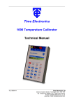
Connect all equipment AC power input lines together and connect them to the H.V. lead of the hipot tester. Connect the RETURN lead of the hi-pot tester to the frame on which the drive and
other auxiliary equipment are mounted.
8.2
The hi-pot tester must have an automatic ramp-up to the test voltage and an automatic rampdown to zero voltage.
Note: If the hi-pot tester does not have automatic ramping, then the hi-pot output must be manually increased to the test voltage and then manually reduced to zero. This procedure must be followed for each machine to be tested. A suggested hi-pot tester is Slaughter Model 2550.
CAUTION! Instantly applying the hi-pot voltage will cause irreversible damage to the drive, which
will void the warranty.
FIGURE 15 – TYPICAL HI-POT TEST SETUP
High Voltage Dielectric Withstand Tester (Hi-Pot Tester)
1
LEAKAGE
2
0
3
AC KILOVOLTS
0mA
10mA
RETURN
TEST
H. V.
RESET
VOLTAGE
Connect All Drive Terminals Together
(Main Power Disconnected)
MAX
ZERO
Adjustable Frequency Drive
AC Line Input
L1
U
L2
V
L3
W
Motor Wires
Frame
Auxiliary Equipment
Connect Hi-Pot
to AC Line Inputs
(Main Power Disconnected)
L1
L2
Chassis
Chassis
Machine Equipment or Frame
9
DRIVE OPERATION
Before operating the drive, read Section 9.2, for instructions on the Digital Keypad Operation. See
Figure 2, on page 10, for the keypad layout.
The 4-digit display can indicate various functions of the drive: Set Frequency, Motor RPM, Output
Current and Voltage, Custom Units, Function Numbers, Function Codes or Values, and Fault Codes.
See Section 9.4, on page 30.
See Section 9.3, on pages 22 – 29, for information on programming the drive. If an error message
appears while programming the drive, see Section 9.5, on page 31.
9.1
START-UP PROCEDURE – After the drive has been properly setup and all connections completed, the start-up procedure can begin. If the AC power has been properly brought to the drive, the
LEDs will indicate the drive’s status, as described in Section 11, on page 41. See Section 9.4, on
page 30, for the Digital Readout Codes.
To start the drive, press the RUN Key. The motor will begin to accelerate to the Set Frequency.
The factory set frequency is 05.00 Hz.
9.2
KEYPAD DESCRIPTION – The Keypad has eight (8) keys, which are used to program drive functions, as described in Table 6, on page 22. The eight (8) LEDs provide indication of the drive’s
21
operational status, as described in Section 11, on page 41. A Main Speed Potentiometer is also
provided to set the Drive Frequency (Function No. 2.00 set to “0001”). See Figure 2, on page 10.
Note: To avoid damage, never operate the keypad with a screwdriver or other sharp-ended tool.
TABLE 6 – KEYPAD DESCRIPTION
Key
Description
Starts or Stops the drive
Changes motor direction.
Up Key: Increases Output Frequency, Set Frequency, Function Number Value, and Code setting.
Down Key: Decreases Output Frequency, Set Frequency, Function Number Value, and Code setting.
Factory programmed to function as a Jog Key. When the key is pressed, it toggles between Run Mode and Jog
Mode (the “JOG/REM” LED will illuminate and the display will show the Jog Frequency Setting (see Function
No. 3.13)). If the key is reprogrammed for Local/Remote Operation (see Function No. 2.02), the key is used to
toggle between Local (Keypad) or Remote Signal Operation (the “LCL/REM” LED will illuminate).*
*Optional IODA or Modbus is required for Local/Remote Operation.
Used to enter Program Mode and Display Mode. If the key is pressed while Set Frequency is displayed, the
previously entered Function Number will be shown. If the key is pressed while Function Number is displayed,
the Set Frequency will be shown. When more than one display function is enabled, the key is used to toggle
between displays. See Figure 22, on page 29.
Left Shift / Reset Key: Moves the changeable digit or Resets the drive to clear a fault.
Reads or Enters a Function Number’s Value or Code setting. The key is also used to read or enter the
frequency setting.
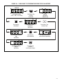
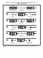
9.3
FLOW CHARTS FOR IMPORTANT PROGRAMMING FUNCTIONS – See Figures 16 – 22, on
pages 23 – 29, for flow charts to program important functions. The flow charts also serve as a
guide to understand the programming procedure.
Note: See Table 7, on page 30, for a description of the Digital Readout Codes.
22
FIGURE 16 – FLOW CHART TO PROGRAM THE DRIVE FOR 50 HZ MOTORS
POWER ON
Press Program Key
to Display
Function No.
Group No.
Digit Flashes
("PGM" LED On)
Press Read Key
to Read Code
Rated Motor Frequency
Code (60 Hz)
Digit Flashes
Press Up Key 1 Time
to Increase Digit
50 Hz Rated Motor Frequency
Code
Digit Flashes
Press Enter Key
to Save New Code
"End" Momentarily Displays
which Confirms Programming
Rated Motor Frequency
Code No.
Digit Flashes
Press Display Key
to Return
to Set Frequency Display
Set Frequency Flashes
("FWD", "STOP", "Hz" LEDs On)
23
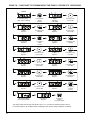
FIGURE 17 – FLOW CHART TO PROGRAM MOTOR CURRENT FROM 6.7 AMPS TO 5.5 AMPS
POWER ON
Set Frequency Flashes
("FWD", "STOP", "Hz" LEDs On)
Press Program Key
to Display
Function No.
Group No.
Digit Flashes
("PGM" LED On)
Press Shift Key 2 Times
to Move Digit
Code No.
Digit Flashes
Press Up Key 1 Time
to Increase Digit
Motor Nameplate Current
Code No.
Digit Flashes
Press Read Key
to Read
Motor Nameplate Current
Motor Nameplate Current *
Digit Flashes
Press Shift Key 1 Time
to Move Digit
Motor Nameplate Current
Digit Flashes
Press Down Key 2 Times
to Decrease Digit
Motor Nameplate Current
Digit Flashes
Press Shift Key 1 Time
to Move Digit
Motor Nameplate Current
Digit Flashes
Press Down Key 1 Time
to Decrease Digit
Motor Nameplate Current
Digit Flashes
Press Enter Key
to Save New
Motor Nameplate Current
"End" Momentarily Displays
which Confirms Programming
Motor Nameplate Current
Code No.
Digit Flashes
Press Display Key
to Return
to Set Frequency Display
*For Models KBDA-27D, 29, the factory setting of Motor Nameplate Current (Function No. 0.01) is 6.7 Amps. See Table 3, on page 10, for the
factory setting of Function No. 0.01 for all other models.
24
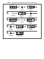
FIGURE 18 – FLOW CHART TO CHANGE SET FREQUENCY FROM 5.00 Hz TO 43.21 Hz
(DRIVE IN THE STOP MODE)*
POWER ON
Set Frequency Flashes
("FWD", "STOP", "Hz" LEDs On)
Press Up Key 1 Time
to Increase Digit
Digit Flashes
Press Shift Key 1 Time
to Move Digit
Digit Flashes
Press Up Key 2 Times
to Increase Digit
Digit Flashes
Press Shift Key 1 Time
to Move Digit
Digit Flashes
Press Down Key 2 Times
to Decrease Digit
Digit Flashes
Press Shift Key 1 Time
to Move Digit
Digit Flashes
Press Up Key 4 Times
to Increase Digit
Digit Flashes
Press Enter Key
to Save New
Set Frequency
New Set Frequency
is Displayed and Flashes
Press Run Key to Run Drive
with New Set Frequency
("STOP" LED Off)
*If Function No. 2.01 is set to “0000”, frequency change requires “ENTER”. Throughout this sequence you must proceed to the next
step within 20 seconds, before the “Press Enter Key” step, or the display will revert to “05.00”. The new value will be stored in Function
No. 3.00.
25
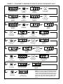
FIGURE 19 – FLOW CHART TO PROGRAM ACCEL TIME FROM 1.5 SECONDS TO 120 SECONDS
POWER ON
Set Frequency Flashes
("FWD", "STOP", "Hz" LEDs On)
Press Program Key
to Display
Function No.
Group No.
Digit Flashes
("PGM" LED On)
Press Up Key 3 Times
to Increase Digit
Group No.
Digit Flashes
Press Shift Key 2 Times
to Move Digit
Code No.
Digit Flashes
Press Up Key 3 Times
to Increase Digit
Accel Time Code
Digit Flashes
Press Read Key
to Read
Accel Time
Accel Time *
Digit Flashes
Press Shift Key 1 Time
to Move Digit
Accel Time
Digit Flashes
Press Down Key 1 Time
to Decrease Digit
Accel Time
Digit Flashes
Press Shift Key 1 Time
to Move Digit
Accel Time
Digit Flashes
Press Up Key 2 Times
to Increase Digit
Accel Time
Digit Flashes
Press Shift Key 1 Time
to Move Digit
Accel Time
Digit Flashes
Press Up Key 1 Time
to Increase Digit
Accel Time
Digit Flashes
Press Shift Key 1 Time
to Move Digit
Accel Time
Digit Flashes
Press Down Key 5 Times
to Decrease Digit
Accel Time
Digit Flashes
"End" Momentarily Displays
which Confirms Programming
Accel Function No.
Digit Flashes
Press Enter Key
to Save New
Accel Time
Press Display Key
to Return
to Set Frequency Display
*The factory setting of Accel Time (Function No. 3.03) is “1.5” seconds. The minimum setting of Accel is
0.1 seconds, therefore, the left digits must be changed first since an Accel setting of 000.0 is not allowed.
26
FIGURE 20 – FLOW CHART TO PROGRAM THE DRIVE TO DISPLAY MOTOR RPM
POWER ON
Set Frequency Flashes
("FWD", "STOP", "Hz" LEDs On)
Press Program Key
to Display
Function No.
Group No.
Digit Flashes
("PGM" LED On)
Press Up Key 4 Times
to Increase Digit
Display Mode
Function No.
Digit Flashes
Press Read Key
to Read
Display Mode Setting
Frequency Display Mode *
Code Setting
Digit Flashes
Press Up Key 1 Time
to Increase Digit
RPM Display Mode
Code Setting
Digit Flashes
Press Enter Key
to Save New
Code Setting
"End" Momentarily Displays
which Confirms Programming
Press Display Key
to Change Display
Set Motor RPM Flashes
(”0150” RPM = 5 Hz)
("FWD", "STOP" LEDs On)
Display Mode
Function No.
Digit Flashes
*The factory setting of Display Mode (Function No. 4.00) is Frequency (“0000”).
27
FIGURE 21 – FLOW CHART TO PROGRAM THE DRIVE TO DISPLAY CUSTOM UNITS “012.0”
POWER ON
Set Frequency Flashes
("FWD", "STOP", "Hz" LEDs On)
Press Program Key
to Display
Function No.
Group No.
Digit Flashes
("PGM" LED On)
Press Up Key 4 Times
to Increase Digit
Display Mode
Function No.
Digit Flashes
Press Read Key
to Read
Display Mode Code
Display Mode
Frequency Code1
Digit Flashes
Press Up Key 2 Times
to Increase Digit
Display Mode
Custom Units Code
Digit Flashes
Press Enter Key
to Save New Code
"End" Momentarily Displays
which Confirms Programming
Press Up Key 1 Time
to Increase Digit
Custom Units
Code No.
Digit Flashes
Press Read Key
to Read
Custom Units Value Setting
Custom Units2
Digit Flashes
Press Shift Key 1 Time
to Move Digit
Custom Units
Digit Flashes
Press Up Key 2 Times
to Increase Digit
Custom Units
Digit Flashes
"End" Momentarily Displays
which Confirms Programming
Custom Units
Code No.
Digit Flashes
Press Read Key
to Read
Custom Units Display Code
Custom Units Display
Whole Numbers Code3
Digit Flashes
Press Enter Key
to Save New Code
"End" Momentarily Displays
which Confirms Programming
Press Display Key
to Change Display
28
Display Mode
Code No.
Digit Flashes
Custom Units Value Flashes4
(”001.0” = 5 Hz
("FWD", "STOP" LEDs On)
Press Up Key 1 Time
to Increase Digit
Press Up Key 1 Time
to Increase Digit
Custom Units Display
Code No.
Digit Flashes
Custom Units Display
One Decimal Place Code
Digit Flashes
Custom Units Display
Function No.
Digit Flashes
Notes: 1. The factory setting of Display Mode (Function
No. 4.00) is Frequency (“0000”). 2. The factory setting
of Custom Units Significant Digits (Function No. 4.01) is
“0100”. 3. The factory setting of Custom Units Display
(Function No. 4.02) is Whole Numbers (“0000”). 4. The
Custom Unit setting “012.0” will be displayed at full
speed.
FIGURE 22 – FLOW CHART SHOWING MOTOR CURRENT, MOTOR VOLTAGE, AND BUS VOLTAGE
ADDED TO THE BASIC DISPLAY*
POWER ON
Set Frequency Flashes
("FWD", "STOP", "Hz" LEDs On)
Press Run Key
to Run Drive
Set Frequency
("STOP" LED Off)
Press Display Key
to Change Display
Group No
Digit Flashes
("PGM" LED On)
Press Display Key
to Change Display
Motor Current
("PGM" LED Off)
Press Display Key
to Change Display
Motor Voltage
Press Display Key
to Change Display
Bus Voltage
Press Display Key
to Change Display
*Function Nos. 4.04 – 4.06 set to “0001”.
29
9.4
4-DIGIT DISPLAY – The 4-digit display provides readout of drive status, operating parameters,
and faults. See Table 7 for the Digital Readout Codes displayed and their descriptions.
WARNING! Do not depend on the LEDs or the 4-Digit Display to no longer be illuminated as a guaranteed power off condition. Be sure the main power switch or
circuit breaker is in the “OFF” position before servicing the drive.
TABLE 7 – DIGITAL READOUT CODES
Display
Description
Display
Description
Drive Stopped – Indicates that the drive is
in the Stop Mode.
Function No. 4.03 set to “0001”.
Parameter Changed – Momentarily flashes.
Indicates that a parameter has been successfully changed.
Function No. Example – A Function No.
consists of a Group No. (digits on the left
side of the decimal point) and a Group Code
No. (digits on the right side of the decimal
point).
Motor Current Display – When the display
is set to show Motor Current, the format will
be ”XX.XA”.
Function No. 4.04 set to “0001”.
Motor Voltage Display – When the display
is set to show Motor Voltage, the format will
be “XXXu”.
Function No. 4.05 set to “0001”.
Bus Voltage Display – When the display is
set to show Bus Voltage, the format will be
“XXXU”.
Function No. 4.06 set to “0001”.
Low Voltage Trip – Indicates that the AC
line input voltage is below the Undervoltage
Trip Point specified in Table 2, on page 9.
Low Voltage Recovery – Indicates that a
Low Voltage Trip occurred and the AC line
input voltage has returned to within the
operating range specified in Table 2,
on page 9.
Overvoltage Trip – Indicates that the AC line
input voltage is above the Overvoltage Trip
Point specified in Table 2, on page 9.
Overvoltage Recovery – Indicates that an
Overvoltage Trip occurred and the AC line
input voltage has returned to within the
operating range specified in Table 2, on
page 9.
Overload Trip (I2t Timeout) – Indicates that
the motor has been overloaded for an
extended period of time.
External Fault Trip – Indicates that an
external fault has occurred at one of the
MFITs of the IODA.
Function Nos. 7.00 – 7.06 set to “0008”.
Current Source Trip – Indicates that the
current signal output (from the IODA) has
been opened.
Short Circuit Fault – Indicates that the drive
detected a short circuit at the motor (phaseto-phase).
AC Line Phase Loss Detection – Indicates
that the drive has detected a loss of one of
the phases in the 3-phase AC line input
applied to Models KBDA-29*, 45, 48.
Data Enter Error – Indicates that the drive is
in the Program Mode and a non-valid
parameter change has been attempted.
Keypad Communication Error – Indicates
that the keypad failed to initialize when the
drive is powered up. This is an abnormal
condition – contact our Sales Department.
Flash Memory Error – Indicates that a flash
memory error on the drive has occurred.
This is an abnormal condition – contact our
Sales Department.
IODA Error – Indicates that the drive has
lost communication with the IODA.
*Model KBDA-29: when used on 3-phase AC line input set for 7.0 Amps or higher (3 HP (2.25 kW)).
30
9.5
FAULT RECOVERY – The drive monitors many faults. See Function No. 1.05, on page 33, for
restarting the drive after a fault has been cleared. See Section 9.4, on page 30, for the Digital
Readout Codes. See Section 11, on page 41, for descriptions of the Diagnostic LEDs. See
Appendix A, on page 42, for IODA faults.
Drive Faults – Undervoltage (“–LU–”), Overvoltage (“–OU–”), Short Circuit at the motor (phase-tophase) (“–SC–”), I2t or I•t Fault (“OL–t”), and Phase Loss Detection (Models KBDA-29*, 45, 48
only) (“–PL–”).
*When used on 3-phase AC line input set for 7.0 Amps or higher (3 HP (2.25 kW)).
10 PROGRAMMABLE FUNCTION SUMMARY LIST
All functions have been factory set, as shown in the tables on pages 32 – 40. The Detailed
Programmable Function List (Part No. A42035) is available – contact our Sales Department.
Programming Mode – When the drive is put into the Programming Mode (see Figure 23), a Function
No. will be displayed. A Function No. consists of a Group No. (digits on the left side of the decimal
point) and a Group No. Code (digits on the right side of the decimal point). The digits can be changed
using the Up and Down Keys. The Left Shift Key is used to move the changeable digit.
When the READ Key is pressed, either a Code or Value will be displayed. Codes have specific descriptions. Values have numeric ranges.
Application Note – The programming of the drive can be performed without a motor connected. On
drives with 3-phase AC line input requirements, the programming can be performed with single-phase
AC line input. The drive’s Phase Loss Detection will not trip the drive without the motor connected.
To program multiple drives, the optional DownLoad Module™ (Part No. 9582) can be used to upload
the drive program and facilitate downloading it to multiple drives.
FIGURE 23 – FUNCTION NO. DESCRIPTION
Function No. which Contains a Code
Press Program Key
to Display
Function No.
Group No. Digit Flashes
(Digital Display Modes)
and
Group No. Code Digits are Shown
(Display Mode)
Press Read Key
to Read Code
Code Displayed
(Frequency)
Function No. which Contains a Value
Press Program Key
to Display
Function No.
Group No. Digit Flashes
(Drive Operating Parameters)
and
Group No. Code Digits are Shown
(Accel Time)
Press Read Key
to Read Value
Value Displayed
(1.5 Seconds)
31
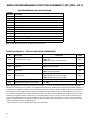
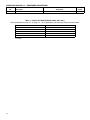
KBDA PROGRAMMABLE FUNCTION SUMMARY LIST (REV. 100.1)
PROGRAMMABLE FUNCTION GROUPS
Function
Group No.
Description
0
Motor and Drive Parameters
1
Run/Stop Mode
2
Frequency Control
3
Drive Operating Parameters
4
Digital Display Modes
5
Onboard Multi-Function Output Relay Operating Mode
6
Drive Status and Reset
7
Multi-Function Input Terminals(1)
8
Multi-Function Output Relays and Output Signal Operation(1)
9
Analog Input Signal Operation(1)
10
Communication Mode(2)
11
Reserved Functions
Note: (1) IODA Option Board required. (2) DIAC Option Board required.
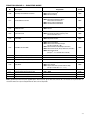
FUNCTION GROUP 0 – MOTOR AND DRIVE PARAMETERS
Function
No.
Description
Range/Code
0000: 60 Hz
0001: 50 Hz
0002: Special (Set by Function No. 0.05)
Factory
Setting
0.00*
Rated Motor Frequency (Hz)
0.01*
Motor Nameplate Current (Amps)
—
0.02*
Motor Type
0000: Inverter Duty, TEFC
0001: External Fan Cooled
0000
0.03*
Torque Mode
0000: Constant Torque (Machinery)
0001: Variable Torque (HVAC)
0000
0.04*
GFCI Operation(2)
0000: GFCI Operation Disabled
0001: GFCI Operation with Standard GFCI
0002: GFCI Operation with Sensitive GFCI
0000
0.05*
Motor Frequency (Hz)(3), (4)
30 – 240
60, 50
0 – 100.0
100(6)
0.06*
(5)
Motor Nameplate Voltage (% Drive Output)
0000
(1)
Notes: (1) Factory Setting is the drive rated output current. See Table 3, on page 10. This function is used to enter the Motor Nameplate
Rated Current, which allows proper operation of the I2t Motor Overload Protection. (2) GFCI operation overrides the Switching Frequency set
by Function No. 3.15. (3) When the drive is set for 50 Hz motors (Function No. 0.00 set to “0001”), the Motor Frequency factory setting will
automatically reset to 50 Hz. (4) The Motor Frequency for standard 50 Hz or 60 Hz motors is set by Function No. 0.00. For custom motors
(e.g., 100 Hz) set Function No. 0.00 to “0002” and Function No. 0.05 to the Motor Nameplate Rated Frequency. (5) This function is used for
motors with non-standard nameplate rated voltage (e.g., 80 Volts AC). (6) The factory set output of the drive is 100% of the AC line input
voltage. In 60 Hz Mode (Function No. 0.00 set to “0000”) the drive output will be 230 Volts, maximum, for 230 Volt motors and 460 Volts,
maximum, for 460 Volt Motors. In 50 Hz Mode (Function No. 0.00 set to “0001”) the drive output will be 220 Volts, maximum, for 220 Volt
motors and 400 Volts, maximum, for 400 Volt Motors.
* Functions which can only be changed while the drive is in the Stop Mode.
32
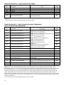
FUNCTION GROUP 1 – RUN/STOP MODE
Function
No.
Description
Range/Code
Factory
Setting
1.00*
Run/Stop-Forward/Reverse Control
0000: Keypad
0001: External Contacts(1)
0002: Communication(2)
0000
1.01*
Forward/Reverse Control
0000: Instant Reverse
0001: Stop Command Must be Given
Prior to Reverse Command
0002: Reverse Command Disabled
0003: Forward Command Disabled
0000
1.02*
Motor Direction
0000: Forward
0001: Reverse
0000
1.03*
Start Command
0000: Accelerates to Last Set Frequency
0001: Accelerates to Lower Frequency Limit
(See Function No. 3.01)
0000
1.04*
Start Mode
0000: Spin Start
0001: Stop Before Restart
0000
1.05*
Auto/Manual Start Mode
0000: Manual Start Mode
0001: Manual Start with Ride-Through
(Set by Function No. 1.06)
0002: Auto Start After Undervoltage Fault Clears
0003: Auto Start All Faults (Except Short Circuit Fault) (3)
0004: Auto Start All Faults
(Except I2t , I•t, and Short Circuit Faults)
0000
1.06*
Ride-Through Time (Seconds)
0.0 – 2.0
1.07*
Number of Restart Attempts
0 – 10
3
1.08*
Auto Start Delay Time (Seconds)
0 – 240
0
1.09*
Stop Mode
0000: Regenerate-to-Stop
0001: Coast-to-Stop
0002: Regeneration with Injection Brake-to-Stop
(Set by Function Nos. 1.11 – 1.13)
1.10*
Holding Torque in Stop Mode (%)
0 – 10
1.11*
Injection Brake Start Frequency (Hz)
0.00 – 240.0
1.12*
Injection Brake Level (%)
0 – 30
1.13*
Injection Brake Time (Seconds)
0.0 – 25.5
0.5
0000
1
0.00
0
0.0
Notes: (1) IODA Option Board required. (2) DIAC Option Board required. (3) For Auto Start, Function No. 1.07 must be set to greater than “0”.
* Functions which can only be changed while the drive is in the Stop Mode.
33
FUNCTION GROUP 2 – FREQUENCY CONTROL
Function
No.
Description
Code
Factory
Setting
0000: Keypad
0001: Built-In Potentiometer
0002: Analog Signal 1(1)
2.00*
Frequency Control
2.01*
Up Key, Down Key Operation Mode
0000: Frequency Change Requires Enter Command
0001: Direct Frequency Change
0002: Keypad Disable
0000
Jog-Local/Remote(3), (4)
0000: Jog Enabled
0001: Jog Disabled
0002: Jog Disabled; Local/Remote Enabled
(Keypad Operation)(1)
0003: Jog Disabled; Local/Remote Enabled
(Built-In Speed Pot Operation)(1)
0000
2.02*
0003: Analog Signal 2(1)
0004: Communication(2)
0005: Up/Down Using MFITs(1)
0000
Notes: (1) IODA Option Board required. (2) DIAC Option Board required. (3) See Jog Mode (Function No. 3.12), Jog Frequency (Function No.
3.13), and Jog Accel/Decel Time (Function No. 3.14). (4) The Jog function can be reprogrammed for Local/Remote (LCL/REM) Operation.
When in Remote Mode Operation, the “JOG/REM” LED will flash.
* Functions which can only be changed while the drive is in the Stop Mode.
FUNCTION GROUP 3 – DRIVE OPERATING PARAMETERS
Function
No.
Description
Range/Code
Factory
Setting
3.00
Stored Set Frequency (Hz)
0.00 – 240.0
5.00
3.01
Lower Frequency Limit (Hz)
0.00 – 240.0
0.00
3.02
Upper Frequency Limit (Hz)(1)
0.00 – 240.0
60.0, 50.0
3.03
Accel Time (Seconds)(2)
0.1 – 180.0
1.5
3.04
Decel Time (Seconds)(2)
0.3 – 180.0
1.5
3.05
S-Curve Time Accel (Seconds)(2)
0.0 – 30.0
0.0
3.06
S-Curve Time Decel (Seconds)(2)
0.0 – 30.0
0.0
3.07*
Skip Frequency (Hz)
0.00 – 240.0
0.00
3.08*
Skip Frequency Bandwidth (± Hz)
0.00 – 2.00
0.00
3.09*
Motor Overload Protection
0000: I2t with Current Limit
0001: I•t with Current Limit
0000
3.10*
3.11
I•t with Current Limit Trip Time (Seconds)
Boost Value (%)
1.0 – 20.0
0.0 – 28.0
3.12*
Jog Mode
0000: Momentary
0001: Latching
0000
6.0
7.0
3.13
Jog Frequency (Hz)
0.00 – 240.0
5.00
3.14
Jog Accel/Decel Time (Seconds)
0.3 – 10.0
1.0
3.15*
Switching Frequency (kHz)
0000: 8
0001: 10
0002: 12
0000
3.16
Flux Vector Compensation (%)
0.0 – 10.0
5.0
Notes: (1) When the drive is set for 50 Hz motors (Function No. 0.00 set to “0001”), the Upper Frequency Limit factory setting will automatically reset to 50 Hz. (2) Time set for Function Nos. 3.03 and 3.04 must be equal to or greater than the time set for Function Nos. 3.05 and
3.06, respectively.
* Functions which can only be changed while the drive is in the Stop Mode.
34
FUNCTION GROUP 4 – DIGITAL DISPLAY MODES
Function
No.
Description
4.00
Display Mode
0000: Frequency
0001: RPM(1)
0002: Custom Units
0000
4.01
Custom Units Significant Digits
0 – 9999
100
4.02
Custom Units Display
0000:
0001:
0002:
0003:
0000
4.03
Display in Stop Mode
0000: Displays Last Run Setting
0001: Displays “StoP”
0002: Displays “0000”
0000
4.04
Motor Current Display(2), (3)
0000: Disabled
0001: Enabled
0000
4.05
Motor Voltage Display(2), (3)
0000: Disabled
0001: Enabled
0000
4.06
Bus Voltage Display(2), (3)
0000: Disabled
0001: Enabled
0000
Range/Code
Whole Numbers
One Decimal Place
Two Decimal Places
Three Decimal Places
Factory
Setting
Notes: (1) Based on 4-pole motor. (2) The Display Key is used to toggle between displays. See Figure 22, on page 29. (3) If Motor Current
Display is enabled, the display will show “XX.XA”. If Motor Voltage Display is enabled, the display will show “XXXu”. If Bus Voltage Display is
enabled, the display will show “XXXU”.
FUNCTION GROUP 5 – ONBOARD MULTI-FUNCTION OUTPUT RELAY OPERATING MODE
Function
No.
Description
Range/Code
0000: Run
0001: Fault(1)
0002: Target Frequency
(Function No. 5.01 ± Function No. 5.02)
0003: Frequency Threshold Level
(> Function No. 5.01 – Function No. 5.02)(2)
0004: Frequency Threshold Level
(< Function No. 5.01 + Function No. 5.02)(3)
0005: I2t or I•t Fault
Factory
Setting
5.00
Relay Operation Mode
5.01
Frequency Reached (Hz)
0.00 – 240.0
0.00
5.02
Frequency Bandwidth (Hz)
0.00 – 30.00
1.00
0000
0006: Load Loss (See Function No. 5.03)
(4)
5.03
Load Loss Threshold
(% Motor Current, set by 0.01)
25 – 90
60
Note: (1) The Output Relay contacts will change state due to all Faults and Recovered Faults. (2) The relay will activate above the setting in
Function No. 5.01 and deactivate below the setting in Function No. 5.01 minus the setting in Function No. 5.02. (3) The relay will activate
below the setting in Function No. 5.01 and deactivate above the setting in Function 5.01 plus the setting in Function No. 5.02. (4) The Load
Loss Threshold function is not functional during acceleration/deceleration or Stop Mode.
35
FUNCTION GROUP 6 – DRIVE STATUS AND RESET
Function
No.
6.00*
6.01*
6.02*
6.03*
6.04*
6.05**
Description
Software Version
Drive Horsepower
Fault Log 1
Fault Log 2
Fault Log 3
Reset Drive to Factory Setting
Code
—
—
—
—
—
1110: 50 Hz Operation
1111: 60 Hz Operation
Factory
Setting
—
—
—
—
—
0000
* Read only.
** Functions which can only be changed while the drive is in the Stop Mode.
FUNCTION GROUP 7 – MULTI-FUNCTION INPUT TERMINALS
(IODA OPTION BOARD REQUIRED)
Function
No.
Description
Range/Code
Preset Frequency Operation(2)
Preset Frequency Operation(2)
Preset Frequency Operation(2)
Up Frequency Command (See Function No. 7.14)(3)
Down Frequency Command
(See Function No. 7.14)(3)
0005: Accel/Decel 2 (See Function No. 7.16)
0006: Forward/Stop Command(4)
0007: Reverse/Stop Command(4)
0008: External Fault (N.O. Contact)
0009: Reset
0010: N.O. Start (2-Wire or 3-Wire Start/Stop)(4)
0011: N.C. Stop (3-Wire Start/Stop)(4)
0012: External Fault (N.C. Contact)
0000:
0001:
0002:
0003:
0004:
Factory
Setting
7.00*
Multi-Function Input Terminal 1 (1)
7.01*
Multi-Function Input Terminal 2 (1)
7.02*
Multi-Function Input Terminal 3 (1)
7.03*
Multi-Function Input Terminal 4 (1)
7.04*
Multi-Function Input Terminal 5 (1)
7.05*
Multi-Function Input Terminal 6 (1)
7.06*
Multi-Function Input Terminal 7 (1)
7.07*
Preset Frequency 1 (Hz)
0.00 – 240.0
5.00
7.08*
Preset Frequency 2 (Hz)
0.00 – 240.0
10.00
20.00
0000
0001
0002
0009
0010
0003
0004
7.09*
Preset Frequency 3 (Hz)
0.00 – 240.0
7.10*
Preset Frequency 4 (Hz)
0.00 – 240.0
25.00
7.11*
Preset Frequency 5 (Hz)
0.00 – 240.0
30.00
7.12*
Preset Frequency 6 (Hz)
0.00 – 240.0
35.00
7.13*
Preset Frequency 7 (Hz)
0.00 – 240.0
40.00
7.14*
Up/Down Frequency Control Mode
0000: Free-Running (5)
0001: Incremental Change (See Function No. 7.15)
0000
7.15*
Increment of Up/Down Frequency (Hz)
0.01 – 30.00
1.00
7.16*
Accel/Decel 2 Time (Seconds)
0.3 – 180.0
1.5
Note: (1) Each of the 7 Multi-Function Input Terminals can be programmed for any of the respective function codes (0000 – 0011).
(2) Preset Frequencies 1 – 7 are obtained by selecting a specific combination of 3 Multi-Function Input Terminals. The specific frequencies
are programmed in Functions 7.07 – 7.13. (3) For Up/Down Frequency Commands (codes “0003” and “0004”), Frequency Control
(Function No. 2.00) must be set to Up/Down Using MFITs (code “0005”). (4) For Forward/Reverse Stop Commands (codes “0006” and
“0007”) and N.O. Start / N.C. Stop (codes “0010” and “0011”), Run/Stop-Forward/Reverse Control (Function No. 1.00) must be set to
External Contacts (code “0001”). (5) The rate of change of the “UP” Control for frequency setting, using external contacts, is proportional to
the Accel Time setting (3.03). The rate of change of the “DOWN” Control for frequency setting, using external contacts, is proportional to the
Decel Time Setting (3.04).
*Functions which can only be changed while the drive is in the Stop Mode.
36
FUNCTION GROUP 8 – MULTI-FUNCTION OUTPUT RELAYS AND
OUTPUT SIGNAL OPERATION (IODA OPTION BOARD REQUIRED)
Function
No.
Description
8.00*
Multi-Function Output Relay 1
(Terms. 23 – 25)
8.01*
Multi-Function Output Relay 2
(Terms. 26 – 28)
8.02*
Multi-Function Open Collector Output 1
(Terms. 11, 12)
8.03*
Multi-Function Open Collector Output 2
(Terms. 13, 14)
Range/Code
0000: Run
0001: Fault (1)
0002: Target Frequency
(Function No. 8.04 ± Function No. 8.05)
0003: Frequency Threshold Level
(> Function No. 8.04 – Function No. 8.05) (2)
0004: Frequency Threshold Level
(< Function No. 8.04 + Function No. 8.05) (3)
0005: I2t or I•t Fault
0006: Load Loss (See Function No. 5.03)
0007: External Fault
0008: Motor Overload (4)
Factory
Setting
0000
0001
0002
0004
8.04*
Frequency Set Point (Hz)
0.00 – 240.0
0.00
8.05*
Frequency Bandwidth (± Hz)
0.00 – 30.00
1.00
8.06*
Analog Output 1 Mode (Terms. 15, 16)
(0 – 5 VDC)
0000: Motor Frequency
0001: Set Frequency
0002: Motor Voltage
0003: Bus Voltage
0004: Motor Current
0000
8.07*
Analog Output 1 Gain (%)
0 – 200
100
8.08*
Analog Output 2 Mode (Terms. 17, 18)
(See Function No. 8.09)
0000: Motor Frequency
0001: Set Frequency
0002: Motor Voltage
0003: Bus Voltage
0004: Motor Current
0000
8.09*
Analog Output 2 Type(5)
0000: 0 – 5 VDC
0001: 0 – 20 mA DC
0002: 4 – 20 mA DC
0000
8.10*
Analog Output 2 Gain (%)
0 – 200
100
Notes: (1) The Multi-Function Output Relays and Open Collector Outputs will change state due to all Faults and Recovered Faults. (2) The
relay will activate above the setting in 8.04 and deactivate below the setting of 8.04 – 8.05. (3) The relay will activate below the setting in
8.04 and deactivate above the setting of 8.04 + 8.05. (4) The Output Relay will change state when the I 2t or I•t Timer starts. (5) Analog
Output 2 Type: For 0 – 5 VDC (code “0000”), set Jumpers J2 and J3, on the IODA, to the “VOLT” Position (factory setting). For 0 – 20 mA DC
(code “0001”) or 4 – 20 mA DC (code “0002”), set Jumpers J2 and J3, on the IODA, to the “CUR” position.
*Functions which can only be changed while the drive is in the Stop Mode.
37
FUNCTION GROUP 9 – ANALOG INPUT SIGNAL OPERATION
(IODA OPTION BOARD REQUIRED)
Function
No.
9.00
Description
Range/Code
Analog Input 1 Gain (%)(1)
0 – 500
Factory
Setting
100
9.01
Analog Input 1 Slope
0000: Positive
0001: Negative
9.02
Analog Input 1 Offset (%)(1)
0 – 100
9.03
Analog Input 1 Type(1)
0000: Unidirectional
0001: Bidirectional
0000
9.04
9.05
Analog Input 1 Response Time (mSec)(1)
Analog Input 2 Gain (%)(2)
2 – 100
0 – 500
2
100
9.06
Analog Input 2 Slope(2)
0000: Positive
0001: Negative
0000
9.07
9.08
9.09
(1)
(2)
0000
0
0 – 100
Analog Input 2 Offset (%)
0
0000: Analog Voltage or Current(3)
0001: PWM(4)
(2)
Analog Input 2 Type
(2)
Analog Input 2 Response Time (mSec)
0000
2 – 100
2
Notes: (1) For Analog Input 1 (Function Nos. 9.00 – 9.04), Frequency Control (Function No. 2.00) must be set to Analog Signal 1 (code
“0002”). (2) For Analog Input 2 (Function Nos. 9.05 – 9.09), Frequency Control (Function No. 2.00) must be set to Analog Signal 2 (code
“0003”). (3) For Current Signal Input, set Jumper J1, on the IODA, to the “CUR” position. (4) 0.15 – 1 kHz (0 – 100% duty cycle).
FUNCTION GROUP 10 – COMMUNICATION MODE (DIAC OPTION BOARD REQUIRED)
Function
No.
10.00*
Description
Assigned Communication Station Number
Range/Code
1 – 247
10.01*
Communications Watchdog Timer
0000: Disabled
0001: Enabled
0000
10.02*
Watchdog Timeout (Seconds)
0.50 – 2.00
0.50
10.03
Operational Command
0
0: Stop
1: Run
1
0: Forward
1: Reverse
2
0: N/A
1: Fault Reset
3
0: JOG-LCL/REM Command Off
1: JOG-LCL/REM Command On
4
0: N/A
1: Preset Frequency 1
5
0: N/A
1: Preset Frequency 2
6
0: N/A
1: Preset Frequency 3
7
0: N/A
1: Preset Frequency 4
8
0: N/A
1: Preset Frequency 5
9
0: N/A
1: Preset Frequency 6
10
0: N/A
1: Preset Frequency 7
11 – 15
Reserved
* Functions which can only be changed while the drive is in the Stop Mode.
38
Factory
Setting
30
—
FUNCTION GROUP 10 – COMMUNICATION MODE
(DIAC OPTION BOARD REQUIRED) (Continued)
Function
No.
10.04
10.05
10.06 **
10.07 **
10.08 **
10.09 **
10.10 **
Description
Range/Code
0
0: Stop
1: Run
1
0: Forward
1: Reverse
2
0: Normal
1: Fault
3
0: JOG-LCL/REM Command Off
1: JOG-LCL/REM Command On
4
0: N/A
1: Preset Frequency 1
5
0: N/A
1: Preset Frequency 2
6
0: N/A
1: Preset Frequency 3
7
0: N/A
1: Preset Frequency 4
8
0: N/A
1: Preset Frequency 5
9
0: N/A
1: Preset Frequency 6
10
0: N/A
1: Preset Frequency 7
11
0: Jog Momentary Mode
1: Jog Latching Mode
12
Reserved
13
0: Local
1: Remote
Drive Status
Drive Status Description
Communications Error Count
Motor Voltage
Motor Current
Bus Voltage
Motor Frequency
14, 15
00
01
02
03
04
05
06
07
08
09
10
11
12
13
—
—
—
—
—
Reserved
Normal Operation
Short Circuit Trip
Current Limit
Current Limit Trip
Undervoltage Trip
Recovered Undervoltage Trip
Overvoltage Trip
Recovered Overvoltage Trip
Stop Mode
Flash Error
External Fault Trip (IODA)
IODA Error
Phase Loss Trip
Current Source Trip (IODA)
Factory
Setting
—
—
—
—
—
—
—
** Read only.
39
FUNCTION GROUP 11 – RESERVED FUNCTIONS
Function
No.
11.00 – 11.09
Description
Reserved
Range/Code
—
Factory
Setting
—
TABLE 8 – MODEL SOFTWARE REVISION CODES (REV. 100.1)
The Programmable Function List, on Pages 32 – 40, is Applicable to the Following* Software Revision Codes
* Or higher.
40
Model No.
Software Revision Code
KBDA-24D
KBDA-27D
KBDA-29
KBDA-45
KBDA-48
29 / 1.02
35 / 1.02
37 / 1.01
38 / 1.01
39 / 1.01
11 DIAGNOSTIC LEDs
The drive contains 8 Status LEDs to provide indication of the drive’s status and operating mode (Hz,
PGM, LCL/REM, STOP, FWD, REV, OL, JOG/REM). See Table 9, for a description of the LEDs.
WARNING! Do not depend on the LEDs or the 4-Digit Display to no longer be illuminated as a
guaranteed power off condition. Be sure the main power switch or circuit breaker is in the
“OFF” position before servicing the drive.
TABLE 9 – LED DESCRIPTIONS
LED
Description
Illuminates when Jog is selected. Flashes when the drive is set for Remote Signal Operation.
Illuminates when the drive is in Overload.
Illuminates when the drive is in the Forward Direction.
Illuminates when the drive is in the Reverse Direction.
Illuminates when the drive is in the Stop Mode.
Illuminates when the display is set to show Output Frequency.
Illuminates when the JOG-LCL/REM Key is reprogrammed for Local (Keypad) and Remote Signal Operation.
Illuminates when the drive is in the Program Mode.
41
APPENDIX A – OPTIONAL IODA INPUT/OUTPUT MULTI-FUNCTION BOARD
The IODA Input/Output Multi-Function Board provides a variety of functions, which include preset frequency, up/down frequency control, signal isolation, isolated output voltage for controlling auxiliary devices,
open collector outputs, and output relay contacts. The IODA mounts on the drive’s PC board with 2 snapins (located on the bottom of the mounting base) and 2 screws (provided). All of the IODA inputs and outputs are isolated from the AC line.
The IODA has a green power on LED (PWR) and a red status LED (STATUS), which are used to provide
operational information of the IODA. See Table 10, below, for a description of the IODA status indicator
LED. See Figure 24, on page 43, for the IODA layout. See Figure 25, on page 43, for the IODA Terminal
Block TB1 Layout. See Table 11, on page 43, for the IODA Terminal Block TB1 Wire and Tightening Torque
Specifications. See Table 12, on page 44, for the IODA Functions and Features. See Sections A1 – A7, on
pages 45 – 49 describing the use of the IODA Multi-Function Input Terminals for Remote Operations. See
Sections A8 – A12, on pages 49 – 54, for Other Functions and Features of the IODA.
Local/Remote Operation – When using the IODA with signal following, it may be appropriate to program
the drive for Local/Remote Operation. In this mode, the drive frequency setting can be toggled between a
process signal and the keypad using the JOG-LCL/REM Key. Set Jog-Local/Remote (Function No. 2.02) to
Jog Disabled; Local/Remote Enabled (“0002”) to change the JOG-LCL/REM Key from Jog Operation to
Local/Remote Operation.
IODA Faults – External Fault Trip (“EF–t”) indicates that a Multi-Function Input Terminal (Function Nos.
7.00 – 7.06 set to “0008”) has closed (and will change the state of the Multi-Function Output Relay
Contacts and the Multi-Function Open Collectors (when Function Nos. 8.00 – 8.03 are set to “0007”)).
Current Source Trip (“CS–t”) indicates that the current signal output (from the IODA) has been opened.
Communication Error (“Err4”) indicates that communication between the drive and the IODA has failed.
WARNING! Do not depend on the LEDs or the 4-Digit Display to no longer be illuminated as a
guaranteed power off condition. Be sure the main power switch or circuit breaker is in the “OFF”
position before servicing the drive.
TABLE 10 – IODA STATUS INDICATOR LED
Condition
Red STATUS LED
Normal Operation
Not Illuminated
Communication Error 1
Flashes 1 Second On and 1 Second Off
Current Source Trip 2
Illuminated
Notes: 1. When a Communication Error occurs, the drive’s 4-Digit Display will show “Err4”. 2. When a Current Source
Trip occurs, the drive’s 4-Digit Display will show “CS-t”.
42
FIGURE 24 – IODA LAYOUT (ALL MODELS)*
8
23
9
24
10
25
11
IODA
26
12
27
13
28
14
Mounting Screw Holes for Large Base
Large Base (Shaded Section)
Mounting Screw Holes for Small Base
20
6
21
7
CUR VOLT VOLT CUR
5
CON2
19
CON2:
Factory
Use Only
22
J2
PWR
15
1
16
2
CON1
17
STATUS
3
18
4
J3
TB1
Terminal Block TB1
Two Snap-Ins to Secure IODA to Mounting Base
MAX2 Trimpot: Signal Scaling for Analog Input 2
VOLT
MAX1
MAX2
J1: Current or Voltage Signal Input Selection
for Analog Input 2
CUR
J1
MAX1 Trimpot: Signal Scaling for Analog Input 1
Status LED (Red)
* The IODA kit contains 2
mounting bases. Use the
small base for Model
KBDA-24D and the
large base for Models
KBDA-27D, 29, 45, 48.
J2 & J3: Current or Voltage Signal Input Selection
for Analog Output 2
Power On LED (Green)
CON1: Used for the Interconnecting
Ribbon Cable to the Drive
FIGURE 25 – IODA TERMINAL BLOCK TB1 LAYOUT
TB1
15
16
1
17
2
19
18
3
4
20
5
21
6
22
7
23
8
9
24 25 26 27 28
10 11 12 13 14
Common Terminals 8, 12, 14, 16, 18, 20, and 22 are all internally connected and are shown shaded.
TABLE 11 – IODA TERMINAL BLOCK TB1 WIRE AND TIGHTENING TORQUE SPECIFICATIONS
Maximum Wire Size (Cu)
Recommended Tightening Torque
AWG
mm2
in-lbs
kg-cm
16
1.3
6
7
43
TABLE 12 – IODA FUNCTIONS AND FEATURES
Terminal Assignment
Multi-Function
Input Terminal Codes
0000: Preset Frequency
Operation1
0001: Preset Frequency
Operation1
0002: Preset Frequency
Operation1
0003: Up Frequency
Command
(See Function
No. 7.14)
0004: Down Frequency
Command
(See Function
No. 7.14)
0005: Accel/Decel 2
(See Function
No. 7.16)
0006: Forward/Stop
Command
0007: Reverse/Stop
Command
0008: External Fault
0009: Reset
0010: N.O. Start
(2-Wire or
3-Wire Start/Stop)
0011: N.C. Stop
(3-Wire Start/Stop)
Multi-Function
Input
Terminals1
(Digital Inputs)
1–7
Power
Supply2
Multi-Function
Outputs2
8: Common 11: Open
9: +5 Volts
Collector 1
10: –5 Volts 12: Common
13: Open
Collector 2
14: Common
Analog
Outputs2
15: Analog Out 1
16: Common
17: Analog Out 2
18: Common
Analog
Inputs2
Relay
Outputs3
19: Analog In 1
20: Common
21: Analog In 2
22: Common
23: RY1 N.O.
24: RY1 Common
25: RY1 N.C.
26: RY2 N.O.
27: RY2 Common
28: RY2 N.C.
Notes: 1. Multi-Function Input Terminals “1” – “7” can be programmed for: 7 Preset Frequencies*, Up or Down Frequency Command,
Accel/Decel 2, Forward/Stop, Reverse/Stop, External Fault, Reset, and 2-Wire/3-Wire Start/Stop. 2. Common Terminals 8, 12, 14, 16, 18, 20,
and 22 are all internally wired together and can be used with any of the Multi-Function Input Terminals “1” – “7”. 3. RY1 Common (Terminal
24) is the contact common only for Relay 1. RY2 Common (Terminal 27) is the contact common only for Relay 2.
*The 7 Preset Frequencies are obtained using a combination of Terminals 1, 2, 1+2, 3, 1+3, 2+3, 1+2+3.
44
PRESET FREQUENCIES
The drive is factory programmed for 7 Preset Frequencies, which can be selected using remote switches
or contacts connected to the Multi-Function Input Terminals “1” – “7”, as shown in Figure 26. See Table
13, for the Multi-Function Input Terminals to select for the preset frequencies. The Preset Frequencies
can be changed from their factory settings by reprogramming Preset Frequencies 1 – 7 (Function Nos.
7.07 – 7.13). When the switch or contact is closed, the preset frequency is selected. In Figure 26, MultiFunction Input Terminals “1”, “2”, and “3” have been arbitrarily chosen. As an example, Function Nos.
7.04, 7.05, and 7.06 can also be programmed to use Multi-Function Input Terminals “5”, “6”, and “7”.
A1.
FIGURE 26 – PRESET FREQUENCY SELECTION SWITCH OR CONTACT CONNECTIONS AND FUNCTION SETTINGS
Function Settings
TB1
15
16
17
18
1
2
3
1
2
3
19
4
20
5
21
6
22
7
23
8
9
24 25 26 27 28
10 11 12 13 14
Function No.
Code
7.00
Multi-Function
Input Terminal 1
0000
Preset Frequency
Operation
7.01
Multi-Function
Input Terminal 2
0001
Preset Frequency
Operation
7.02
Multi-Function
Input Terminal 3
0002
Preset Frequency
Operation
TABLE 13 – PRESET FREQUENCY SELECTION
Multi-Function Input Terminals to Select
Terminal
1
Terminal
2
Terminal
3
•
•
•
•
A2.
Hz
(Factory Setting)
No.
Function No.
1
7.07
5.00
2
7.08
10.00
3
7.09
20.00
•
4
7.10
25.00
•
5
7.11
30.00
•
•
6
7.12
35.00
•
•
7
7.13
40.00
•
•
Preset Frequency
UP/DOWN FREQUENCY COMMAND
The Multi-Function Input Terminals can be used for remote Up/Down Frequency control in lieu of the
Keypad or the Built-In Potentiometer. Connect the normally open switches or contacts to any two
respective Multi-Function Input Terminal (“1” – “7”). Connect the common of the switches or contacts to
Terminal “8” (common). When the “Up” switch or contact is closed, the drive output frequency will
increase. When the “Down” switch or contact is closed, the drive output frequency will decrease. See
Figure 27, on page 46.
Set Frequency Control (Function No. 2.00) to Up/Down Using MFITs (“0005”). Set the respective MultiFunction Input Terminal (Function Nos. 7.00 – 7.06), which will be used for “Up”, to “0003”. Set the
respective Multi-Function Input Terminal (Function Nos. 7.00 – 7.06), which will be used for “Down”, to
“0004”. In Figure 27, on page 46, Multi-Function Input Terminals “4” and “5” have been arbitrarily chosen.
Also see Up/Down Frequency Control Mode (Function No. 7.14) to set the switch or contact mode for
“Free Running” (Function No. 7.14 set to “0000” (factory setting)) or “Incremental Change” (Function
No. 7.14 set to “0001”). In “Free Running” mode, the rate of change of the “UP” control is proportional
to the Accel Time (Function No. 3.03) and the rate of change of the “Down” control is proportional to
the Decel Time (Function No. 3.04). In “Incremental Change” mode, the rate of change of the “UP” or
“Down” control is set by Function No. 7.15 (range is 0.01 – 30.00 Hz (factory set to 1.00 Hz)).
45
FIGURE 27 – UP/DOWN FREQUENCY CONTROL SWITCH OR CONTACT CONNECTIONS AND FUNCTION SETTINGS
Function Settings
TB1
15
17
16
1
2
18
3
19
21
20
5
4
6
22
23
8
7
9
24 25 26 27 28
10 11 12 13 14
Up Down
Function No.
Range/Code
2.00
Frequency
Control
0005
Up/Down
Using MFITs
7.03
Multi-Function
Input Terminal 4
0003
Up Frequency
Command
7.04
Multi-Function
Input Terminal 5
0004
Down Frequency
Command
7.14
Up/Down Frequency
Control Mode
0000 or 0001
Free-Running or
Incremental
7.15*
Increment of Up/Down
Frequency
0.01 – 30.00 Hz
Set to the Desired
Frequency
* Use with Function No. 7.14 code “0001” only.
A3.
ACCEL/DECEL 2
The drive provides a secondary Accel/Decel Time setting, which can be remotely selected with a
switch or contact connected to any Multi-Function Input Terminal “1” – “7”, as shown in Figure 28.
Set the respective Multi-Function Input Terminal (Function Nos. 7.00 – 7.06) to Accel/Decel 2 (“0005”).
The Accel/Decel 2 time is set in Function No. 7.16 (factory set to 1.5 seconds). When the switch or
contact is closed, the Accel/Decel 2 setting is selected. Accel/Decel 2 overrides the Accel and Decel
settings in Function Nos. 3.03 and 3.04. In Figure 28, Multi-Function Input Terminal “6” has been
arbitrarily chosen.
FIGURE 28 – ACCEL/DECEL 2 SWITCH OR CONTACT CONNECTION AND FUNCTION SETTINGS
Function Settings
TB1
15
16
1
17
2
19
18
3
4
20
5
21
6
22
7
Accel/Decel 2
A4.
46
23
8
9
Function No.
Range/Code
7.05
Multi-Function
Input Terminal 6
0005
Accel/Decel 2
7.16
Accel/Decel 2
Time
0.3 – 180.0
Set to the
Desired Time
24 25 26 27 28
10 11 12 13 14
FORWARD/STOP AND REVERSE/STOP COMMAND
The Multi-Function Input Terminals can be used for remote Forward/Stop and Reverse/Stop operation
by connecting a switch or contact to any Multi-Function Input Terminal “1” – “7”, as shown in Figure
29, on page 47. When the “Forward/Stop” switch or contact is closed, the drive will run in the forward
direction and when the switch or contact is opened, the drive will stop. When the “Reverse/Stop”
switch or contact is closed, the drive will run in the reverse direction and when the switch or contact
is opened, the drive will stop.
Set Run/Stop-Forward/Reverse Control (Function No. 1.00) to External Contacts (“0001”). Set the
respective Multi-Function Input Terminal (Function Nos. 7.00 – 7.06), which will be used for
“Forward/Stop”, to “0006”. Set the respective Multi-Function Input Terminal (Function Nos. 7.00 –
7.06), which will be used for “Reverse/Stop”, to “0007”. In Figure 29, on page 47, Multi-Function Input
Terminals “4” and “7” have been arbitrarily chosen.
FIGURE 29 – FORWARD/STOP-REVERSE/STOP SWITCH OR CONTACT CONNECTIONS AND FUNCTION SETTINGS
Function Settings
TB1
15
16
1
17
2
18
3
19
20
5
4
Forward/Stop
A5.
21
6
22
7
23
8
9
24 25 26 27 28
10 11 12 13 14
Reverse/Stop
Function No.
Code
1.00
Run/Stop-Forward/Reverse
Control
0001
External
Contacts
7.03
Multi-Function
Input Terminal 4
0006
Forward/Stop
Command
7.06
Multi-Function
Input Terminal 7
0007
Reverse/Stop
Command
EXTERNAL FAULT
The Multi-Function Input Terminals can be used to provide feedback to the drive when a fault condition occurs in auxiliary equipment. The connection to the Multi-Function Input Terminals is typically
from a normally open relay, contact, or PLC, as shown in Figure 30. When the circuit is closed, the
drive will “stop” and the display will show “EF-t”.
Set the respective Multi-Function Input Terminal (Function Nos. 7.00 – 7.06), which will be used for
“External Fault”, to “0008”. In Figure 30, Multi-Function Input Terminal “5” has been arbitrarily chosen.
FIGURE 30 – EXTERNAL FAULT AUXILIARY EQUIPMENT SWITCH OR CONTACT CONNECTION AND FUNCTION SETTING
Function Setting
Code
7.04
Multi-Function
Input Terminal 5
0008
External
Fault
TB1
Function No.
15
16
1
18
17
2
3
19
4
20
5
21
6
22
7
23
9
8
24 25 26 27 28
10 11 12 13 14
Auxiliary Equipment
A6.
RESET
The Multi-Function Input Terminals can be used to reset the drive, after a fault has been cleared, by
connecting a switch or contact to any Multi-Function Input Terminal “1” – “7”, as shown in Figure 31.
Set the respective Multi-Function Input Terminal (Function Nos. 7.00 – 7.06), which will be used for
“Reset”, to “0009”. In Figure 31, Multi-Function Input Terminal “4” has been arbitrarily chosen.
FIGURE 31 – RESET SWITCH OR CONTACT CONNECTION AND FUNCTION SETTING
Function Setting
Code
7.03
Multi-Function
Input Terminal 4
0009
Reset
TB1
Function No.
15
16
1
17
2
18
3
19
4
20
5
21
6
22
7
23
8
9
24 25 26 27 28
10 11 12 13 14
Reset
47
A7.
2-WIRE AND 3-WIRE START/STOP
A remote Start/Stop Switch or Contact can be used to start and stop the motor in lieu of the
RUN/STOP Key on the Keypad. The Start/Stop Switch or Contact can be connected for 2-Wire or 3Wire configuration, as described below.
2-WIRE START/STOP SWITCH OR CONTACT CONNECTION
2-Wire Start/Stop requires a maintained switch or contact. Connect the switch or contact to the
respective Multi-Function Input Terminal “1” – “7” and to Terminal “8” (common), as shown on Figure 32.
Set Run/Stop-Forward/Reverse Control (Function No. 1.00) to External Contacts (“0001”). Set the
respective Multi-Function Input Terminal (Function Nos. 7.00 – 7.06), which will be used for “Normally
Open Start”, to “0010”. In Figure 32, Multi-Function Input Terminal “3” has been arbitrarily chosen.
Note: Function code “0011” should not be programmed when using 2-Wire Start/Stop.
FIGURE 32 – 2-WIRE START/STOP SWITCH OR CONTACT CONNECTION AND FUNCTION SETTINGS
Function Settings
TB1
15
16
1
17
2
19
18
3
4
20
5
21
6
22
7
23
8
9
Function No.
Code
1.00
Run/Stop-Forward/Reverse
Control
0001
External
Contacts
7.02
Multi-Function
Input Terminal 3
0010
Normally
Open Start
24 25 26 27 28
10 11 12 13 14
Start/Stop
(Close to Start, Open to Stop)
3-WIRE START/STOP SWITCH OR CONTACT CONNECTION
3-Wire Start/Stop requires momentary switches or contacts. Connect the normally open side of
the switch or contact to the respective Multi-Function Input Terminal “1” – “7”. Connect the normally
closed side of the switch or contact to the other respective Multi-Function Input Terminal “1” – “7”.
Connect the common of the switch or contacts to Terminal “8”. See Figure 33, on page 49.
Set Run/Stop-Forward/Reverse Control (Function No. 1.00) to External Contacts (“0001”). Set the
respective Multi-Function Input Terminal (Function Nos. 7.00 – 7.06), which will be used for “Normally
Open Start”, to “0010”. Set the respective Multi-Function Input Terminal (Function Nos. 7.00 – 7.06),
which will be used for “Normally Closed Stop”, to “0011”. In Figure 33, on page 49, Multi-Function
Input Terminals “1” and “2” have been arbitrarily chosen.
Notes: 1. When an MFIT (Terminal 2) is assigned code “0011”, the MFIT (Terminal 1) assigned code
“0010” automatically changes from maintained to momentary operation. 2. When using 3-Wire
Start/Stop, “Stop” will override “Start”, even if the Start Switch or Contact is kept in the “Start
position.
48
FIGURE 33 – 3-WIRE START/STOP SWITCH OR CONTACT CONNECTION AND FUNCTION SETTINGS
Function Settings
TB1
15
16
1
17
2
18
3
Start Stop
19
4
20
21
6
5
22
23
8
7
9
24 25 26 27 28
10 11 12 13 14
Momentarily close the Start Switch or Contact to run the drive.
Momentarily open the Stop Switch or Contact to stop the drive.
Function No.
Code
1.00
Run/Stop-Forward/Reverse
Control
0001
External
Contacts
7.00
Multi-Function
Input Terminal 1
0010
Normally Open
Start
7.01
Multi-Function
Input Terminal 2
0011
Normally Closed
Stop
OTHER FUNCTIONS AND FEATURES OF THE IODA
A8.
SIGNAL FOLLOWING
An analog voltage (unidirectional or bidirectional), current, or PWM signal input can be used to control
motor speed in lieu of the Keypad or the Built-In Potentiometer. The drive output will linearly follow the
signal input. The inputs can be programmed for the desired gain, slope, offset, and response time.
See Analog Input Signal Operation (Function Group 9).
Analog Input 1 – Connect the signal input to Terminal “19” and the common to Terminal “20”, as
shown in Figure 34. See settings for Analog Input 1 (Function Nos. 9.00 – 9.04). Set Frequency
Control (Function No. 2.00) to Analog Input 1 (“0002”). For unidirectional voltage input, set Analog
Input 1 Type (Function No. 9.03) to Unidirectional ((“0000”) (factory setting)). For bidirectional voltage
input, set Function No. 9.03 to Bidirectional (“0001”). See Table 14, on page 50, for Analog Input 1
electrical ratings.
If the Analog Input 1 signal is higher than 5 Volts, use Trimpot MAX1 to attenuate it. Apply the maximum signal input and set the drive for full speed output and observe the display. Rotate Trimpot
MAX1 counterclockwise until the drive output frequency begins to drop. Then rotate Trimpot MAX1
clockwise until the display returns to the maximum output frequency.
FIGURE 34 – ANALOG INPUT 1 SIGNAL VOLTAGE FOLLOWING CONNECTION AND FUNCTION SETTINGS
Function Settings
TB1
15
17
16
1
2
18
3
19
4
20
5
+
0 - ±5 Volts DC V
22
21
6
7
23
8
9
24 25 26 27 28
10 11 12 13 14
MAX1
Function No.
Range/Code
2.00
Frequency
Control
0002
Analog
Signal 1
9.00
Analog Input 1
Gain
0 – 500
Set to the
Desired Gain
9.01
Analog Input 1
Slope
0000 or 0001
Positive or
Negative
9.02
Analog Input 1
Offset
0 – 100
Set to the
Desired Offset
9.03
Analog Input 1
Type
0000 or 0001
Unidirectional or
Bidirectional
9.04
Analog Input 1
Response Time
2 – 100
Set to the
Desired Time
-
49
TABLE 14 – ANALOG INPUT 1 ELECTRICAL RATINGS
Parameter
Specification
Factory setting
Voltage Range (Volts DC)
0 – ±5
0–5
MAX1 Scaling Trimpot Range (Volts DC)
0 – 24
5
Analog Input 2 – Connect the signal input to Terminal “21” and the common to Terminal “22”, as
shown in Figure 35. See settings for Analog Input 2 (Function Nos. 9.05 – 9.09). Set Frequency
Control (Function No. 2.00) to Analog Input 2 (“0003”). For voltage input, set Jumper J1 to the “VOLT”
position and set Analog Input 2 Type (Function No. 9.08) to Analog Voltage or Current ((“0000”) (factory setting)). For current input, set Jumper J1 to the “CUR” position and set Analog Input 2 Type
(Function No. 9.08) to Analog Volgage or Current ((“0000”) (factory setting)). For PWM input set
Jumper J1 to the “VOLT” position and set Analog Input 2 Type (Function No. 9.08) to PWM (“0001”).
See Table 15 for Analog Input 2 electrical ratings.
If the Analog Input 2 signal is higher than the input signals specified in Table 15, use Trimpot MAX2 to
attenuate it. Apply the maximum signal input and set the drive for full speed output and observe the
display. Rotate Trimpot MAX2 counterclockwise until the drive output frequency begins to drop. Then
rotate Trimpot MAX2 clockwise until the display returns to the maximum output frequency.
FIGURE 35 – ANALOG INPUT 2 SIGNAL CURRENT FOLLOWING CONNECTION AND FUNCTION SETTINGS
Function Settings
Function No.
Range/Code
2.00
Frequency
Control
0003
Analog
Signal 2
9.05
Analog
Input 2 Gain
0 – 500
Set to the
Desired Gain
9.06
Analog
Input 2 Slope
0000 or 0001
Positive or
Negative
VOLT
TB1
15
16
1
17
2
18
3
19
4
20
5
21
6
22
7
23
8
9
24 25 26 27 28
10 11 12 13 14
MAX2
+
0 - 20 mA DC
CUR
J1
9.07
0 – 100
Analog
Set to the
Input 2 Offset Desired Offset
-
0000
Analog
Voltage or
Current
9.08
Analog
Input 2 Type
9.09
2 – 100
Analog Input 2
Set to the
Response Time Desired Time
TABLE 15 – ANALOG INPUT 2 ELECTRICAL RATINGS
Parameter
Specification
Factory setting
Voltage Range (Volts DC)
0–5
0–5
MAX2 Scaling Trimpot Range (Volts DC)
0 – 24
5
Current Range (mA DC)
0 – 20*
—
270
—
0.15 – 1, 0 – 100
—
Input Impedance for Current Mode (Ω)
PWM (kHz, Duty Cycle)
* If using 4 – 20 mA DC signal input, the offset setting in Function No. 9.07 must be increased from “0%” (factory setting) to “20%”. Set
Jumper J1 to the “CUR” position.
50
ANALOG SIGNAL OUTPUT
Two analog signal outputs are provided, which will linearly follow the parameter programmed in
Analog Output 1 Mode (Function No. 8.06) and Analog Output 2 Mode (Function No 8.08). They can
be used to monitor Motor Frequency, Set Frequency, Motor Voltage, Bus Voltage, and Motor Current.
See Table 16, for the Analog Outputs 1 and 2 Electrical Ratings.
A9.
Analog Output 1 – Connect the auxiliary device signal input to Terminal “15” and the common to
Terminal “16”, as shown in Figure 36. Set Analog Output 1 Mode (Function No. 8.06) for the desired
parameter to be monitored (factory set to Motor Frequency (“0000”)). Set Analog Output 1 Gain
(Function No. 8.07) for the desired signal gain (factory set to 100%). Analog Output 1 provides a 0 – 5
Volt DC signal output.
Analog Output 2 – Connect the auxiliary device signal input to Terminal “17” and the common to
Terminal “18”, as shown in Figure 36. Set Analog Output 2 Mode (Function No. 8.08) for the desired
parameter to be monitored (factory set to Motor Frequency (“0000”)). Set Analog Output 2 Type
(Function No. 8.09) to ((“0000”) (factory setting)) for 0 – 5 Volt DC output. Set Analog Output 2 Type
(Function No. 8.09) to “0001” for 0 – 20 mA DC output. Set Analog Output 2 Type (Function No. 8.09)
to “0002” for 4 – 20 mA DC output. Set Analog Output 2 Gain (Function No. 8.10) for the desired signal gain (factory set to100%).
FIGURE 36 – ANALOG OUTPUTS 1 AND 2 CONNECTIONS AND FUNCTION SETTINGS
Function Settings
15
16
1
17
2
18
3
19
4
20
5
21
6
22
7
23
8
CUR VOLT
TB1
VOLT CUR
J2
24 25 26 27 28
10 11 12 13 14
9
J3
SIG COM SIG COM
Output 1 Output 2
Function No.
Range/Code
8.06
Analog
Output 1
Mode
0000 – 0004
Motor Frequency,
Set Frequency,
Motor Voltage, Bus
Voltage, Motor Current
8.07
Analog
Output 1
Gain
0 – 200
Set to the
Desired Gain
8.08
Analog
Output 2
Mode
0000 – 0004
Motor Frequency,
Set Frequency,
Motor Voltage, Bus
Voltage, Motor Current
8.09
Analog
Output 2
Type
0000 – 0002
0 – 5 Volts DC,
0 – 20 mA DC,
4 – 20 mA DC
8.10
Analog
Output 2
Gain
0 – 200
Set to the
Desired Gain
TABLE 16 – ANALOG OUTPUTS 1 AND 2 ELECTRICAL RATINGS
Parameter
Analog Outputs 1 and 2 Voltage Range (Volts DC)
Analog Output 2 Current Range (mA DC)
Analog Output 2 Impedance for Current Mode (Ω)
Specification
Factory setting
0–5
0–5
0 – 20, 4 – 20
—
150
—
A10. REMOTE MAIN SPEED POTENTIOMETER
A remote Main Speed Potentiometer (5 kΩ) can be used in lieu of the Keypad or the Built-In
Potentiometer. The Main Speed Potentiometer can be connected for bidirectional, forward, or reverse
motor speed control, as described on page 52.
51
BIDIRECTIONAL MOTOR OPERATION (Use Analog Input 1 Only)
Connect the potentiometer to Terminals “9” (+5 Volts), “19” (Analog Input 1), and “10” (-5 Volts), as
shown in Figure 37. Set Frequency Control (Function No. 2.00) to Analog Input 1 (“0002”). In this
mode, the remote potentiometer is set for zero speed at 50% rotation. Rotating the potentiometer
clockwise will increase motor frequency in the forward direction. Rotating the potentiometer counterclockwise will increase motor frequency in the reverse direction.
FIGURE 37 – BIDIRECTIONAL MOTOR OPERATION MAIN SPEED POTENTIOMETER CONNECTION AND FUNCTION SETTING
Function Setting
Function No.
Code
2.00
Frequency
Control
0002
Analog
Signal 1
VOLT
TB1
15
16
1
17
2
Main Speed
Potentiometer
19
18
3
4
20
5
21
6
22
7
23
8
9
24 25 26 27 28
10 11 12 13 14
MAX2
High
Wiper
Low
CUR
J1
FORWARD MOTOR OPERATION
Analog Input 1 – Connect the potentiometer to Terminals “9” (+5 Volts), “19” (Analog Input 1), and
“20” (Common). Set Frequency Control (Function No. 2.00) to Analog Input 1 (“0002”).
Analog Input 2 – Connect the potentiometer to Terminals “9” (+5 Volts), “21” (Analog Input 2), and
“22” (Common). Set Frequency Control (Function No. 2.00) to Analog Input 2 (“0003”).
REVERSE MOTOR OPERATION
Analog Input 1 – Connect the potentiometer to Terminals “10” (-5 Volts), “19” (Analog Input 1), and
“20” (Common). Set Frequency Control (Function No. 2.00) to Analog Input 1 (“0002”).
Analog Input 2 – Connect the potentiometer to Terminals “10” (-5 Volts), “21” (Analog Input 2), and
“22” (Common). Set Frequency Control (Function No. 2.00) to Analog Input 2 (“0003”).
A11. MULTI-FUNCTION OUTPUT RELAYS
Two Multi-Function Output Relays are provided, which can be programmed for Run, Fault, Target
Frequency, Frequency Threshold Level (> 8.04 – 8.05), Frequency Threshold Level (< 8.04 + 8.05), I2t
or I•t Fault, Load Loss, External Fault, and Motor Overload. Relay 1 is factory programmed to operate
as a “Run” Relay (Function No. 8.00 set to “0000” (factory setting)). Relay 2 is factory programmed to
operate as a “Fault” Relay (Function No. 8.01 set to “0001” (factory setting)). The maximum allowable
contact load current is 2 Amps. See Figure 38, on page 53.
Note: If the drive “stops”, due to an External Fault Trip (“EF–t”), which indicates that a Multi-Function
Input Terminal (Function Nos. 7.00 – 7.06 set to “0008”) has closed, the Multi-Function Output Relay
Contacts will change state (when Function No. 8.00 or 8.01 is set to “0007”).
Multi-Function Output Relay 1 Contacts
Normally Open (N.O.) Contact: TB1 Terminal “23”.
Common (COM): TB1 Terminal “24” (contact common for Relay 1 only).
Normally Closed (N.C.) Contact: TB1 Terminal “25”.
52
Multi-Function Output Relay 2 Contacts
Normally Open (N.O.) Contact: TB1 Terminal “26”.
Common (COM): TB1 Terminal “27” (contact common for Relay 2 only).
Normally Closed (N.C.) Contact: TB1 Terminal “28”.
FIGURE 38 – MULTI-FUNCTION OUTPUT RELAY CONTACTS CONNECTIONS AND FUNCTION SETTINGS
Function Settings
Relay 1
Relay 2
Function No.
Code
0000 – 0008
Run, Fault, Target Frequency,
Frequency Threshold Level
8.00
(> 8.04 – 8.05),
Multi-Function Frequency Threshold Level
Output Relay 1
(< 8.04 + 8.05), I2t or I•t
TB1
Fault, Load Loss, External
Fault, Motor Overload
15
16
1
17
2
19
18
3
4
21
20
5
6
22
7
23
8
9
24 25 26 27 28
10 11 12 13 14
N.O. COM N.C. N.O. COM N.C.
Relay 1
Relay 2
0000 – 0008
Run, Fault, Target Frequency,
Frequency Threshold Level
8.00
(> 8.04 – 8.05),
Multi-Function Frequency Threshold Level
Output Relay 2
(< 8.04 + 8.05), I2t or I•t
Fault, Load Loss, External
Fault, Motor Overload
A12. MULTI-FUNCTION OPEN COLLECTOR OUTPUTS
Two Open Collector Outputs are provided, which can be programmed for Run, Fault, Target
Frequency, Frequency Threshold Level (> 8.04 – 8.05), Frequency Threshold Level (< 8.04 + 8.05), I2t
or I•t Fault, Load Loss, External Fault, and Motor Overload. Open Collector Output 1 is factory programmed to operate as a Target Frequency indicator (Function No. 8.02 set to “0002” (factory setting)). Open Collector Output 2 is factory programmed to operate as a Frequency Threshold Level
(< 8.04 + 8.05) indicator (Function No. 8.03 set to “0004” (factory setting)). See Figure 39, on page 54.
See Table 17, on page 54, for the Multi-Function Open Collector Output electrical Ratings.
Multi-Function Open Collector Output 1
Collector (O.C.): TB1 Terminal “11”.
Emitter (COM): TB1 Terminal “12” (internal circuit common).
Multi-Function Open Collector Output 2
Collector (O.C.): TB1 Terminal “13”.
Emitter (COM): TB1 Terminal “14” (internal circuit common).
53
FIGURE 39 – MULTI-FUNCTION OPEN COLLECTOR CONNECTIONS AND FUNCTION SETTINGS
Function Settings
Function No.
Output 1
Output 2
TB1
15
16
1
17
2
18
3
20
19
4
5
22
21
6
7
23
8
9
24 25 26 27 28
10 11 12 13 14
O.C. COM O.C. COM
Output 1 Output 2
Code
0000 – 0008
Run, Fault, Target Frequency,
Frequency Threshold Level
8.02
(> 8.04 – 8.05),
Multi-Function
Open Collector Frequency Threshold Level
Output 1
(< 8.04 + 8.05), I2t or I•t
Fault, Load Loss, External
Fault, Motor Overload
0000 – 0008
Run, Fault, Target Frequency,
Frequency Threshold Level
8.03
(> 8.04 – 8.05),
Multi-Function
Open Collector Frequency Threshold Level
Output 2
(< 8.04 + 8.05), I2t or I•t
Fault, Load Loss, External
Fault, Motor Overload
TABLE 17 – MULTI-FUNCTION OPEN COLLECTOR OUTPUTS ELECTRICAL RATINGS
Parameter
Specification
Factory setting
Maximum Voltage (Volts DC)
24
—
Maximum Load Current (mA DC)
60
0 – 20
Minimum External Resistance (Ω)
400
—
54
– NOTES –
55
LIMITED WARRANTY
For a period of 18 months from the date of original purchase, KB Electronics, Inc. will repair or replace
without charge, devices which our examination proves to be defective in material or workmanship. This
warranty is valid if the unit has not been tampered with by unauthorized persons, misused, abused, or
improperly installed and has been used in accordance with the instructions and/or ratings supplied.
The foregoing is in lieu of any other warranty or guarantee, expressed or implied. KB Electronics, Inc. is
not responsible for any expense, including installation and removal, inconvenience, or consequential
damage, including injury to any person, caused by items of our manufacture or sale. Some states do
not allow certain exclusions or limitations found in this warranty and therefore they may not apply to
you. In any event, the total liability of KB Electronics, Inc., under any circumstance, shall not exceed
the full purchase price of this product. (rev 2/2000)
COPYRIGHT © 2009 KB Electronics, Inc.
All rights reserved. In accordance with the United States Copyright Act of 1976, no part of this
publication may be reproduced in any form or by any means without permission in writing from
KB Electronics, Inc. (8/2002)
KB ELECTRONICS, INC.
12095 NW 39th Street, Coral Springs, FL 33065-2516 • (954) 346-4900 • FAX (954) 346-3377
Outside Florida Call Toll Free (800) 221-6570 • [email protected]
www.kbelectronics.com
(A40402) – Rev. B – 2/2009
Print Code
RECONDITIONING THE BUS CAPACITORS
If this drive has been in storage for over one year it
is necessary to recondition the power supply bus
capacitors. To recondition the bus capacitors, apply
the AC Line, with the drive in the Stop Mode, for a
minimum of one hour. Not following this procedure
will cause the bus capacitors to fail.
(A40194) – Rev. A00 – 7/31/2013