1
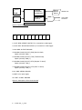
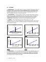
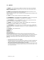
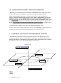
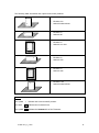
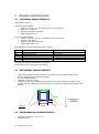
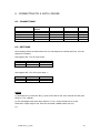
TILTOMETER V1.0 USER’S MANUAL Copyright 2012, the Symmetron Company. Fourth Edition in English, May 2012. No part of this publication may be reproduced, stored in a retrieval system, or transmitted, in any form by any means, without the prior written permission of Symmetron Company. Information furnished by Symmetron is believed to be accurate and reliable; however, no responsibility is assumed for its use. No license is granted by implication or otherwise. Symmetron is a registered trademark. Stylitis and Tiltometer are trademarks of the Symmetron Company. All other trademarks belong to their respective owners. WARRANTY The Symmetron Company warrants its products shall be free from defects on materials and workmanship under normal use for the period of 1 year. Symmetron's obligation under this warranty shall not arise until buyer returns the defective product, freight prepaid to Symmetron's facility or another specified location. The only responsibility of Symmetron under this warranty is, at its option, to replace or repair, free of charge, any defective component of such products. THE WARRANTY DOES NOT EXTEND TO AND SHALL NOT APPLY TO: 1. Products which have been repaired or altered by other than Symmetron's personnel, unless Buyer has properly altered or repaired the products in accordance with procedures previously approved in writing by Symmetron. 2. Products, which have been subject to misuse, neglect, accident, improper installation, or direct lightning strikes. THE WARRANTY AND REMEDIES SET FORTH ABOVE ARE IN LIEU OF ALL OTHER WARRANTIES EXPRESSED OR IMPLIED, ORAL OR WRITTEN, EITHER IN FACT OR BY OPERATION OF LAW. THE SYMMETRON COMPANY SHALL HAVE NO LIABILITY FOR INCIDENTAL OR CONSEQUENTIAL DAMAGES OF ANY KIND ARISING OUT OF THE SALE, INSTALLATION, OR USE OF ITS PRODUCTS. RETURN OUTSIDE GREECE Contact Symmetron for authorization and shipping instructions. SYMMETRON ELECTRONIC APPLICATIONS TEL: +30-210-603-4002, FAX: +30-210-603-4003 e-mail: [email protected] Internet: http://www.symmetron.gr/ Made in Greece. 2 S-UME-TILT_1_0-004 N. Hadzidakis – T. Katsabakou Co. 54, Leontariou St. 15351 Pallini, Greece MANUFACTURER’S DECLARATION OF CONFORMITY I, the undersigned, hereby declare that the equipment specified conforms to the below Directives and Standards. Standards to which Conformity is Declared EMC Emmisions: ΕΝ61326:1998 EMC Immunity: ΕΝ61326:1998 Protection: EN60529:1992 Description of Equipment Angle sensor. Model Tiltometer Batch of product covered Serial numbers: from 0 to 2000 Date and Place Pallini, Attica, Greece, December 1, 2006. Authorized signatory on behalf of the manufacturer N. Hadzidakis Name: N. E. Hadzidakis Title: Director N. Hadzidakis – T. Katsabakou Co. S-UME-TILT_1_0-004 3 TABLE OF CONTENTS 1 2 3 INTRODUCTION .......................................................................................... 5 GENERAL DESCRIPTION .............................................................................. 5 COMMUNICATION WITH THE USER .............................................................. 7 3.1 SERIAL PORT ....................................................................................... 7 3.2 SETTINGS............................................................................................ 8 3.3 QUERIES ............................................................................................. 9 3.4 CONNECTION OF THE SERIAL PORT WITH GSM MODEM ...................... 10 4 PLACEMENT POSITIONS & CORRESPONDING OUTPUTS ............................... 10 5 TECHNICAL SPECIFICATIONS ..................................................................... 12 5.1 ELECTRICAL CHARACTERISTICS.......................................................... 12 5.2 MECHANICAL CHARACTERISTICS ........................................................ 12 5.3 ENVIRONMENTAL CHARACTERISTICS .................................................. 12 6 CONNECTING TO A DATA LOGGER ............................................................. 13 6.1 CONNECTIONS................................................................................... 13 6.2 SETTINGS.......................................................................................... 13 4 S-UME-TILT_1_0-004 1 INTRODUCTION The Tiltometer is a product for measuring the angle (verticality) of met masts or for monitoring the tracker angle movement in a solar plant. The angle is measured in space. The angle information will either be recorded on a data logger (analog sensor outputs) or will be monitored via the RS232 port, or both. Alternatively, serial communication can also be RS485 or RS422. Tiltometers with Serial Number beginning from 000L- support this feature. Serial Numbers beginning with 000K- or of any other form (old form), support RS232 serial communication. The Tiltometer is designed to watch the condition of mast or the tracker movement by measuring its angle. As such, it allows you to: Communicate, via its serial port with a computer and obtain data as needed. You can change settings as you wish. Connect the Tiltometer with a data logger and record the measurements, which are provided as analog voltage outputs. In case of a met mast, connect the serial port of the Tiltometer to a GSM Modem and have it send an SMS message to a preset number, if tilt angle exceeds a preset angle. This way a possible (and expensive) mast fall may be prevented. The above operations are performed simultaneously with the sampling of measured data and without affecting their integrity. 2 GENERAL DESCRIPTION According to the block diagram, shown in Figure 1, the Tiltometer has the following characteristics: Two voltage outputs, one for elevation angle and one for azimuth, with output range 0~2.5 volts or 0~5 volts. They can be connected as inputs to a data logger, PLC, etc. A built-in RS232 port, connected to a screw terminal (for old Serial Numbers) for local or remote (via GSM Modem) communication. Analytic description of terminals is given in Figure 2. For Serial Numbers beginning from 000K- (RS232) or 000L- (RS485 ή RS422), there is not a built-in serial port, but pins are assigned to specific cable colors, as seen in figure 3. Connect the serial port pins (for connection to a PC or GSM modem) according to it. The outputs update with frequency 2Hz, i.e. every 500ms. Power Supply: 6 to 15 VDC. It is calibrated and re-calibrated via software. S-UME-TILT_1_0-004 5 Sensor MCU RS232/ RS485/ RS422 STORED PROGRAM (FIRMWARE) Sensor DAC START-UP CIRCUIT POWER SUPPLY Figure 1:General diagram 10 9 8 7 6 5 4 3 2 1 1 OUT AZIM: AZIMUTH OUTPUT, for connection to data logger. 2 OUT ELEV: ELEVATION OUTPUT, for connection to data logger. 3 AN. GND: OUTPUT GROUND 4 Standard model (RS-232): RXD (Receive Data) Option (RS-422): RDA (-) 5 Standard model (RS-232): TXD (Transmit Data) Option (RS-422): RDB (+) 6 Standard model (RS-232): RTS (Request To Send) Option (RS-422): TDA (-) 7 Standard model (RS-232): CTS (Clear To Send) Option (RS-422): TDB (+) 8 S. GND: SERIAL GROUND 9 BAT+12V: input supply 10 BAT-: SUPPLY GROUND Figure 2: Description of the screw terminal 6 S-UME-TILT_1_0-004 SERIAL I/O VOLTAGE OUTPUT PURPLE.............ANALOG OUT ELEVATION BLUE................ANALOG OUT AZIMUTH YELLOW…….AN_GND RED……+12V BLACK……….GND GREY…………+TX (RS422)....+RX/TX (RS485)....TXD (RS232) BROWN……….-TX (RS422)....-RX/TX (RS485)....RXD (RS232) WHITE………+RX (RS422)....+RX/TX (RS485)....CTS (RS232) PINK………….-RX (RS422)....-RX/TX (RS485)....RTS (RS232) GREEN……GND Figure 3: Pin assignment with cable color 3 COMMUNICATION WITH THE USER 3.1 SERIAL PORT Tiltometers with (old) Serial Number which does not begin with 000L- (RS422 or RS485) or 000K- (RS232) have a built-in RS232 serial port. Otherwise, connect the pins of a serial port according to figure 3 of the previous chapter. It allows local set-up with a PC or data transfer. Pin assignment: Pin Pin Pin Pin Pin 2 3 5 7 8 Receive Data Line (RXD), the pin 4 of terminal (input) Transmit Data Line (TXD), the pin 5 of terminal (output) Ground, the pins 3, 8, 10 of terminal Request To Send (RTS), the pin 6 of terminal (output) Clear To Send (CTS), the pin 7 of terminal (input) Communication speed is fixed at 9600 baud with 8 data bits, 1 stop bit, no parity bit. For communication between Tiltometer and PC connect a suitable cable and use the HyperTerminal software. S-UME-TILT_1_0-004 7 3.2 SETTINGS i) "!ALARMANGLE=". Sets an alarm angle. The value is compared to the Elevation angle. If the Elevation angle becomes smaller than the ALARMANGLE then an SMS message with tilt information will be transmitted. The information may be exploited to prevent damage to an installation. Allowed values are from 0 to 89. For example: “!ALARMANGLE=80” etc. The value of 90 disables this feature. See also paragraph 3.4. ii) "!ALARMPHONE=". This sets the phone number to send the SMS message. The phone number may be in local or international form (with country prefix), and up to 20 digits long. If both are registered and located in the same country enter the local form (for example, “!ALARMPHONE=9876543210”), otherwise enter the international form (for example, “!ALARMPHONE=+309876543210”, where the country’s international prefix is 30) iii) "!RANGE=". This command sets the output voltage range at 0~2.5 Volts (“!RANGE=HALF”) or 0~5 Volts (“!RANGE=FULL”). Output voltages represent angle; output 0 provides the elevation and output 1 provides the azimuth. The following figures show what you get with these settings. Full Range 3 2,5 2 1,5 1 0,5 0 -100 -50 0 50 100 6 Output Voltage(Volts) Output Voltage(Volts) Half Range 5 4 3 2 1 0 -100 Elevation Angle(Degrees) -50 0 50 100 Elevation Angle(Degrees) Figure 5 Figure 3 Full Range Output Voltage(Volts) Output Voltage(Volts) Half Range 3 2,5 2 1,5 1 0,5 0 0 100 200 300 400 6 5 4 3 2 1 0 0 Azimuth Angle(Degrees) Figure 4 100 200 300 400 Azimuth Angle(Degrees) Figure 6 iv) "!HANDSHAKE=". This command sets the serial communication handshake options. The Tiltometer uses hardware control (RTS and CTS signals) when “!HANDSHAKE=HARDWARE”. The Tiltometer uses no handshake when you set “!HANDSHAKE=NONE”. You may want to use hardware handshake when, for instance, you want to inform a connected modem that the Tiltometer is about to transmit a message. 8 S-UME-TILT_1_0-004 3.3 QUERIES i) "!ANGLE?". This command returns: ANGLE=E,A. Where Ε is the value of the elevation angle and is between -90 and 90 degrees and Α is the value of the azimuth angle which is between 0 and 360 degrees. ii) "!START". This command starts sending a stream of angle pairs in the form E, A. The Tiltometer sends a new angle pair every 500 milliseconds. If this command is executed no other commands will be interpreted with the exception of the “!STOP” command. iii) "!STOP". It is used to stop the execution of the !START command. iv) "!ALARMANGLE?". This command returns: ALARMANGLE=y, where y is the angle which has been defined by the "!ALARMANGLE=" command (see 3.2. Settings i)). v) "!ALARMPHONE?". Returns ALARMPHONE=Ν, where Ν is the number which we have defined by the command "!ALARMPHONE="(3.2. Settings ii)). vi) "!RANGE?". This command returns: RANGE =HALF or RANGE =FULL, according to its definition by the command "!RANGE="(see 3.2. Settings iii)). vii) "!HANDSHAKE?". This command returns the handshake options setting: HANDSHAKE =NONE or HANDSHAKE =HARDWARE, depending on the command "!HANDSHAKE="(see 3.2. Settings iv)). viii) "!STATUS?". This command returns: TILTOMETER Vx.x FIRMWARE Vx.x UPTIME=k ANGLE ALARMS=l LAST ANGLE ALARM =n The first line shows the hardware version number, the second is the firmware version number, the third is the time (k), in seconds, which has passed since the system is power up, the fourth is the number of angle alarms (l) generated since power up and the fifth is a number (n) representing the time the last angle alarm was generated in seconds, since power up. o o o All settings and queries return OK or ERROR. All settings and queries must be terminated by the characters CR (ASCII 13 decimal) and LF (ASCII 10 decimal). If using HyperTerminal, make sure that you have checked the option ‘Send Carriage Return characters along with Line Feeds’ . The Tiltometer does not echo back the characters it is receiving. This means that in order to see the commands you are typing in HyperTerminal, you must check the option ‘Local echo of typed characters’. S-UME-TILT_1_0-004 9 3.4 CONNECTION OF THE SERIAL PORT WITH GSM MODEM Optionally, the Tiltometer may be connected to a GSM Modem via the serial port. You can use the serial connection through the modem for configuration or data acquisition. Setting the ALARMANGLE parameter to a value less than 90, the alarm mechanism is activated. When the Elevation angle becomes smaller than the ALARMANGLE, then an SMS message to a preset number (ALARMPHONE) will be automatically send. Messages will be sent every 24 hours, until the Elevation angle increases above the ALARMANGLE value. If the alarm condition is removed before completion of the 24-hour interval, then an SMS will still be sent. The first SMS will not be sent until the power-up time is 24 hours. The SMS contains the following message: "Elevation Angle is X degrees. Alarm Angle is Y degrees. Dangerous Tilt!!! " where X is the current elevation angle and Y is the preset ALARMANGLE. GSM modems from Siemens and Wavecom have been tested and perform well with this function. 4 PLACEMENT POSITIONS & CORRESPONDING OUTPUTS A general idea of the space in which the tiltometer can move and typical values of the elevation and azimuth angle are given in figure 7 (E: elevation, A: azimuth). Please notice that when Elevation is at 90 degrees, then the Azimuth cannot be determined; this is because the projection of the Z-axis on the horizontal plane becomes zero. Positive Z-axis E=90, A= indeterminate Positive Y-axis E=0, A=90 Positive X-axis E=0, A=180 E=0, A=0 E=0, A=270 E=-90, A=indeterminate Figure 7 10 S-UME-TILT_1_0-004 The following table summarizes the outputs versus basic positions. Absolute vertical position. • • Elevation=90 Azimuth indeterminate Elevation=0 Azimuth=90 Elevation=0 Azimuth=0 or 360 Elevation=0 Azimuth=270 Elevation=0 Azimuth=180 Elevation=-90 Azimuth indeterminate • • • • LEGEND The symbol • indicates the screw terminal’s position. The hatch indicates the horizontal level. The symbol indicates the bottom side of the Tiltometer. S-UME-TILT_1_0-004 11 5 TECHNICAL SPECIFICATIONS 5.1 ELECTRICAL CHARACTERISTICS Please refer to Figure 2. OUT AZIM: Output Azimuth. Range: 0-2.5 volts or 0-5 volts, representing 0 to +360 degrees. Resolution: 1,4 degrees. Accuracy: better than 4 degrees. Output update rate: 2 Hz. OUT ELEV: Output Elevation. Range: 0-2.5 volts or 0-5 volts, representing –90 to +90 degrees. Resolution: 0,7 degrees. Accuracy: better than 2 degrees. Output Update Rate: 2 Hz. Communication connection: 9600 baud, 8 bits, no parity. PIN TXD RXD RTS CTS S. GND Standard (RS-232) Output Transmit output Input Receive input Output ελέγχου ροής (handshake) Input ελέγχου ροής (handshake) Serial Ground Option (RS-422) RDB (+) Input RDA (-) Input TDA (-) Output TDB (+) Output Serial Ground Step response (any value to final value): 8 seconds. Power Supply: 6 to 15 VDC supply, 8 mA (typical). 5.2 MECHANICAL CHARACTERISTICS Connections of input and output: All user I/O connections are on internal 10-position screw terminal. Cable passes through IP65 PG7 gland. Box: Cast aluminium IP65. Dimensions: 115 x 65 x 30 mm. Mounting: directly on wind masts with diameters between 70 and 150mm, using clamp. This is possible if the 8 mm-high dome nuts (included) are used as shown in Figure 8 (box’s smallest side shown): 8 mm AZIMUTH 0 (NORTH) Figure 8 5.3 65mm ENVIRONMENTAL CHARACTERISTICS Operating Temperature: -25 to +75 C. Protection: IP65. 12 S-UME-TILT_1_0-004 6 CONNECTING TO A DATA LOGGER 6.1 CONNECTIONS TILTOMETER Screw Screw Screw Screw Screw #10 BAT#9 BAT+12V #1 AZIMUTH #2 ELEVATION #3 AN. GND GENERIC DATA LOGGER ANALOG CHANNEL ANALOG CHANNEL ANALOG GROUND (1) STYLITIS-41 STYLITIS-101 ANY ANALOG IN ANY ANALOG IN GROUND ANY ANALOG IN ANY ANALOG IN GROUND BATTERY BAT BAT + - 6.2 SETTINGS These settings deliver recorded values from 0 to 360 degrees for azimuth and from -90 to 90 degrees for elevation: Data loggers with a 0 to 5V input range: SLOPE OFFSET AZIMUTH 72.0 0.0 ELEVATION 36.0 -90.0 Data loggers with a 0 to 2.5V input range SLOPE OFFSET AZIMUTH 144.0 0.0 (2) : ELEVATION 72.0 -90.0 NOTES: (1) On Stylitis-101, connect the AN [-] inputs to the GND on the screw terminal. Set the input range to 0~5V, Unipolar. (2) For data loggers with input range equal to 0~2.5V, use the RS232 port to set the Tiltometer’s output range to half. Issue the command: !RANGE=HALF (See 3.2). (3) S-UME-TILT_1_0-004 13