1
1
IDS816 User Manual 700-283-01H Issued January 2009
Contents
Glossary-------------------------------------------------------------------------------------------------------------------6
1.
Introduction to the IDS 816 ---------------------------------------------------------------------------7
2.
Before Operating Your Alarm System ------------------------------------------------------------7
3.
Understanding the Keypad Indicators------------------------------------------------------------8
4.
The Keypad Buzzer-----------------------------------------------------------------------------------------9
5.
Programmable Functions -----------------------------------------------------------------------------9
6.
6.1
6.2
6.3
6.3.1
6.4
6.4.1
6.5
6.6
Arming the Control Panel --------------------------------------------------------------------------- 10
Away Arming------------------------------------------------------------------------------------------------10
Quick Away Arm--------------------------------------------------------------------------------------------10
Stay Arm-----------------------------------------------------------------------------------------------------10
How to Stay Arm-------------------------------------------------------------------------------------------11
Quick Stay Arm---------------------------------------------------------------------------------------------11
How to Stay Arm and Go---------------------------------------------------------------------------------11
Key-switch or Remote Arming (If Fitted)--------------------------------------------------------------12
Auto Arm-----------------------------------------------------------------------------------------------------12
7.
7.1
7.2
Disarming the Control Panel----------------------------------------------------------------------- 12
How to Disarm with a User Code----------------------------------------------------------------------12
How to Disarm Using a Key-switch or Remote-----------------------------------------------------12
8.
8.1
Bypassing Zones--------------------------------------------------------------------------------------- 13
Bypassing/Un-bypassing a Zone----------------------------------------------------------------------13
9.
9.1
9.2
9.3
9.4
Emergency Alarms ------------------------------------------------------------------------------------ 13
Fire Alarms--------------------------------------------------------------------------------------------------13
Panic Alarms------------------------------------------------------------------------------------------------13
Medical Alarms---------------------------------------------------------------------------------------------14
Duress Alarms----------------------------------------------------------------------------------------------14
10.
Alarm Memory ------------------------------------------------------------------------------------------ 14
11.
11.1
User Codes----------------------------------------------------------------------------------------------- 15
Adding, Deleting and Editing User Codes-----------------------------------------------------------15
12.
User Program Mode----------------------------------------------------------------------------------- 15
13.
Explanation of Programmable Options--------------------------------------------------------- 18
13.1
Add a new User Code - Option 0----------------------------------------------------------------------16
13.2
Edit a User Name - Option 1 (LCD Keypads Only)------------------------------------------------16
13.3
Edit a Selected User Code - Option 2----------------------------------------------------------------16
13.4
View a User Code Slot Number - Option 3----------------------------------------------------------17
13.5
User Code Properties - Option 4-----------------------------------------------------------------------17
13.5.1 Explanation of User Code Properties-----------------------------------------------------------------18
13.5.1.1 Duress Code------------------------------------------------------------------------------------------------18
13.5.1.2 Maid's Code-------------------------------------------------------------------------------------------------18
2
IDS816 User Manual 700-283-01H Issued January 2009
13.5.1.3 Global Arm/Disarm Code--------------------------------------------------------------------------------18
13.6
Assign a User Code to Partitions - Option 5--------------------------------------------------------18
13.7
Adding User Remotes - Option 8----------------------------------------------------------------------19
13.8
Delete a User Code - Option 9 (Code Known)-----------------------------------------------------19
13.9
Delete a User Code - Option 10 ("Slot" Known)----------------------------------------------------19
13.10 Viewing a User Name - Option 11 (Slot Known)---------------------------------------------------20
14.
14.1
14.2
Stay Zones ----------------------------------------------------------------------------------------------- 20
How to Select a Stay Profile-----------------------------------------------------------------------------20
How to Program Stay Zones----------------------------------------------------------------------------20
15.
15.1
Buzz Zones----------------------------------------------------------------------------------------------- 21
How to Program a Buzz Zone--------------------------------------------------------------------------21
16.
16.1
Chime Zones -------------------------------------------------------------------------------------------- 22
How to Program Chime Zones-------------------------------------------------------------------------22
17.
Viewing Trouble Conditions------------------------------------------------------------------------ 22
18.
Changing a Partition ---------------------------------------------------------------------------------- 23
19.
Output Control via a Keypad----------------------------------------------------------------------- 23
Index25
Index----------------------------------------------------------------------------------------------------------------------25
Tables
Table 1 User Programming Options ------------------------------------------------------------------------ 15
Table 2 User Code Properties -------------------------------------------------------------------------------- 18
Table 3 Trouble Conditions------------------------------------------------------------------------------------ 23
3
IDS816 User Manual 700-283-01H Issued January 2009
4
IDS816 User Manual 700-283-01H Issued January 2009
5
IDS816 User Manual 700-283-01H Issued January 2009
Glossary
Alarm Memory
This is the history of the most recent tampers and violations that occurred the last time the system was
armed, as well as which zones were bypassed.
Arm
Arming the system sets the system into the ARMED mode. In this mode, violating a zone will activate an
alarm condition. If the system is programmed correctly, this will cause an appropriate reporting code to
be sent to the monitoring company.
Bypass
Bypassing deactivates a zone. When the panel is ARMED, violation of a bypassed zone will be ignored.
Disarm
Disarming deactivates the system. Fire, medical and panic functions remain active while the system is
disarmed.
Entry/Exit Zones
These are zones that you may pass through during the entry/exit delay period without triggering an alarm.
Their purpose is to provide a means by which you can exit after arming the system – and a means of
getting to the panel to disarm it after gaining access to the premises. Generally, the last exit point of the
building and the first entry point, this is the front door of the home in most cases.
Follower Zone
A zone that may be temporarily violated during the Exit Zone delay period or after a violation of an
Entry/Exit zone. This allows the user (limited time) access to disarm the system when entering or exiting,
and sufficient time to exit before arming comes into effect. A Follower zone will behave as per an Instant
zone if violated prior to the violation of an Entry/Exit zone when armed.
Instant Zone
When the system is armed, violation of an Instant Zone will immediately cause an alarm condition to be
registered.
Partition
A partition is a group of zones that may be armed and disarmed independently without affecting zones or
users assigned to other partitions. The alarm panel may have been programmed by your installer to have
1 or 2 partitions. Typically, a guest cottage appended to a main house may be partition 2, and the main
house partition 1.
Stay Arm
This is an arming mode that allows certain pre-programmed, Stay zones to be bypassed (temporarily
disabled) while the system is armed. If you arm the system and do not leave the premises within the exit
delay, the system will assume that you are staying home and will stay arm.
Stay Arm and Go
Arming that allows the user to Stay arm and leave the premises.
Stay Zone
A zone that is bypassed automatically when the system is Stay armed.
6
IDS816 User Manual 700-283-01H Issued January 2009
Violate
A zone is “violated” when a sensor connected to a zone input registers a door opening, a window
opening, somebody moving in the room, or glass breaking – depending on the sensor for that zone.)
Zone
A zone is a specific area of your premises monitored by sensors, for that zone, that detect violations
(doors/windows opening or people moving) in that area.
1.
Introduction to the IDS 816
The IDS 816 is a versatile, microprocessor-based eight-zone alarm panel. It has two partitions and can
be expanded to monitor sixteen burglary zones. Most features are optional and may be programmed
directly through the keypad. There is a dedicated panic zone, monitored siren output, auxiliary power
outputs and five (expandable to seven) programmable outputs that may be programmed to perform
various trigger/switching functions.
For correct operation, these Alarm Panels must be used in conjunction with the specified
transformer/battery combination and appropriate peripheral sensors and signalling devices.
2.
7
Before Operating
Operating Your
Your Alarm System
System
Read the entire manual carefully and keep it in an accessible place.
Note that your security system should be installed and serviced by a qualified security
professional who should instruct you regarding the level of protection provided and the operation
of the system.
Should you have any questions regarding the operation of the system, contact your security
company representative.
Note that your system should be tested on a regular basis. Before testing the system, please
notify your security company of your intention to do so.
NEVER disconnect the mains power, as the back-up battery will eventually discharge thereby
causing the control panel to shutdown.
Note that a security system cannot prevent emergencies. It is only intended to alert you and (if
applicable) your central station, of an emergency situation.
Note that smoke and heat detectors may not detect all fire situations.
IDS816 User Manual 700-283-01H Issued January 2009
3.
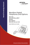
Understanding the Keypad Indicators
Refer to the labelled pictures of the keypads.
1.
ARMED Indicator (Red)
On
System Armed
Off
System Disarmed
Flashing
Alarm Condition
(Check Alarm Memory zone details BEFORE re-arming)
2.
AWAY Indicator (Red)
On
System Armed in Away Mode
Off
System Disarmed / Armed in Stay Mode
Flashing
User Programming (Chime/Buzz/Stay zones)
3.
POWER Indicator (Red)
On
Mains Power is Present
Flashing
Trouble Condition
4.
READY Indicator (Green)
On
5.
System is Ready to be Armed
ZONE Indicators (Yellow)
On
Zone Bypassed
Off
Zone Clear
Flashing
Zone Violated or Tampered
8
IDS816 User Manual 700-283-01H Issued January 2009
4.
The Keypad Buzzer
[#] WITH any key from [0] to [3] for 1 second
The keypad includes a buzzer that is used for audible signalling and verification of certain keypad
functions. There are 4 possible volume settings: loud, medium, soft and click, loud being the default
setting. To program the keypad volume, use the following table:
Key Entry
[#] [3]
[#] [2]
[#] [1]
[#] [0]
Keypad Buzzer
Buzzer Options
Loud (Default setting)
Medium
Soft
Click
To change the volume (for this example to the “soft” setting) press the [#] and [1] key simultaneously for
1 second (long press). After a 1 second time lapse, the keypad will respond with a beep at the new
volume setting. This is a keypad specific setting, and applies to the keypad that this operation is
performed on.
All zones programmed as Chime or Buzz zones, will sound with a loud buzz regardless of the
keypad volume set above.
5.
Programmable Functions
Functions include:
9
Quick Away Arm
Quick Stay Arm
Arm with Entry/Exit or Follower zones violated
Stay Arm
Stay Arm and Go
Forced Arm
Push to Arm
Siren Sound on Arm/Disarm (single toot – arm / double toot – disarm)
Panic Alarm
Fire Alarm
Medical Alarm
Chime zones
Buzz zones
Zone Tamper
Arm with Key-switch or Remote Control
IDS816 User Manual 700-283-01H Issued January 2009
6.
Arming the Control Panel
6.1
Away Arm
[#] [USER CODE]
(Leave via Entry/Exit zone)
1.
2.
3.
4.
5.
6.2
Ensure that the READY indicator is on. If not, check that all protected doors and windows are
closed and that all movement has ceased in areas covered by motion detectors. If necessary,
close the front door.
Press the [#] key.
Enter a valid [USER CODE]. If an incorrect code is entered, the keypad buzzer will beep three
times. In the event of an error press the [#] key and re-enter the code.
The ARMED indicator will come on and the keypad buzzer will beep repeatedly for the duration of
the exit delay. Any bypassed zones will be indicated by a steady on zone indicator.
Leave only via a designated exit route (leaving by any other can set off the alarm). The panel will
arm at the end of the exit delay.
Quick Away Arm
Hold down the [1] key until the beep
If this function is enabled, it is possible to AWAY arm by simply holding down the [1] key until the keypad
buzzer sounds and the arming process begins.
NOTE:
If the partition is already STAY armed, this key will initialise AWAY arming. It is therefore possible to
change directly from STAY armed to AWAY armed.
6.3
Stay Arm
Stay arming allows the user to monitor selected perimeter zones and bypass interior zones. The user can
remain on the premises with access to designated areas during the STAY ARM cycle. Any zone that may
be violated accidentally should be programmed as a BUZZ ZONE. When violated, a BUZZ ZONE will
cause the keypad buzzer to sound for thirty (30) seconds before sounding the siren. Entering a valid
USER CODE before the siren sounds will silence the keypad buzzer and prevent the siren from sounding.
To provide greater flexibility the panel caters for the programming of two different STAY
PROFILES. Each STAY PROFILE contains a unique combination of STAY, BUZZ and ALARM zones that
caters for a particular STAY ARM requirement.
Example:
PROFILE 1 might be used when the family goes to bed in the evening. In this profile, some interior zones
may be programmed as alarm zones or buzz zones, whereas PROFILE 2 is used while watching
television when all interior zones would be bypassed.
(See How to Select a Stay Profile, under Stay Zones)
10
IDS816 User Manual 700-283-01H Issued January 2009
6.3.1
How to Stay Arm
Arm
[#] [USER CODE]
(Do not leave premises)
1.
2.
3.
4.
5.
6.
7.
8.
9.
6.4
Select the required STAY PROFILE (See page 19)
Ensure that the READY indicator is on. If not, check that all protected doors and windows are
closed and that all movement has ceased in the areas covered by motion detectors.
Press the [#] key.
Enter a valid [USER CODE]. If an incorrect code is entered, the keypad will give an error beep. In
the event of an error press the [#] key and re-enter the [USER CODE].
The ARMED indicator will come on and the keypad buzzer will sound for the duration of the exit
delay.
DO NOT violate the Entry/Exit zone (normally the front door). If the Entry/Exit zone is violated the
system will arm in the AWAY mode.
Upon expiry of the exit delay, the AWAY indicator will remain off.
Any STAY zones will be automatically bypassed (indicated by a steadily on indicator).
Ensure that you enter only those areas that are bypassed.
Quick Stay Arm
Hold down the [5] key until the beep
It is possible to STAY arm by holding down the [5] key until the keypad buzzer sounds. The panel will
immediately arm into the stay mode without any exit delay. All stay zones will be bypassed.
NOTE:
OTE:
Holding the button down again will cause the panel to toggle between stay profiles. This STAY profile
then becomes the active profile and the panel will STAY arm using this profile - until you elect to switch
profiles again.
6.4.1
How to Stay Arm and Go
Hold down the [6] key until the beep
This is a single key arm function that allows the user to STAY arm and leave the premises. If a partition is
already stay armed, holding down the [6] key initiates an exit delay, thus allowing the user to leave the
premises without disarming. At the end of the exit delay, the partition will re-arm in the same stay profile it
was armed in before the [6] key was held down.
1.
2.
Hold down the [6] key until the keypad buzzer sounds. The keypad buzzer will sound for the
duration of the exit delay. Only leave via a designated exit route.
At the end of the exit delay, the ARMED indicator will come on and the AWAY indicator will remain
off. All stay zones will be bypassed.
NOTE:
NOTE:
Holding down the [6] key until the keypad buzzer sounds also ensures an entry delay on entering the
premises.
11
IDS816 User Manual 700-283-01H Issued January 2009
6.5
1.
2.
3.
KeyKey-switch or Remote Arming (If Fitted)
Fitted)
Ensure that the READY indicator is on before leaving.
Leave and close the door (remembering to lock!)
Activate the remote or the key-switch. (A remote can be used to Stay Arm or Away Arm.) The panel
will arm in the away mode.
NOTE:
If a remote control is used it is advisable to have the siren toot on arm function enabled. This provides
verification that the system has armed. (Speak to your installer about this feature)
6.6
Auto Arm
The panel may be programmed to arm automatically at a pre-programmed time. Should the premises be
occupied at the time of auto-arming, a valid user code entered during the pre-arm delay will terminate the
arming sequence. The pre-arm delay is signalled by an exit beep.
7.
Disarming the Control Panel
7.1
How to Disarm with a User Code
[#] [USER CODE]
1.
2.
3.
4.
5.
6.
Enter the premises through a designated entry route. Entering via any other route will cause an
alarm.
As soon as the Entry/Exit zone is violated, the entry delay will begin. The keypad buzzer will sound
for the duration of the entry period.
Press the [#] key and enter a valid [USER CODE].
Once the system disarms, the ARMED indicator will turn off and the keypad buzzer will stop
sounding.
If no valid user code has been entered prior to the expiry of the entry delay period an alarm
condition will be registered.
If the entry period is too short, have your installer change the entry delay period.
NOTE
NOTE:
If a strobe (or flashing light) has been installed and an alarm condition is registered, the strobe will
continue flashing after the siren has stopped sounding. Entering a valid user code will cancel the strobe.
7.2
1.
2.
How to Disarm Using a KeyKey-switch or Remote
Activate the remote or key-switch.
The system will disarm and the remote indicator (if installed) will turn off. If the siren toot on disarm
option is enabled, the siren will provide a double toot when the panel is disarmed
NOTE:
Speak to your installer about activating this feature.
12
IDS816 User Manual 700-283-01H Issued January 2009
8.
8.1
Bypassing Zones
The term BYPASS is used to describe a zone that has been deactivated; i.e. violation of a
bypassed zone is ignored and will not cause an alarm condition.
Once the system is armed, it is not possible to bypass zones.
All bypassed zones will be automatically cancelled each time the panel is disarmed and must be
re-bypassed before the next arming.
Bypassing
Bypassing/Un
ing/Un/Un-bypassing
ypassing a Zone
Hold down [9] key until the beep,
then enter [ZONE NUMBER] [*] [#]
1.
2.
3.
4.
5.
Ensure that the panel is not armed (Armed LED OFF).
To enter bypass mode, hold down the [9] key for one second (until the keypad buzzer sounds).
The Away LED will flash, and bypassed zones will be indicated by zone LED’s that are on.
Entering a zone number [ZONE NUMBER] [*] will toggle the corresponding LED. For example,
[2] [*] will turn LED 2 on (if it was off) and off (if it was on).
Turn on the LED’s corresponding to the zones you need to bypass. The LED zone indicators
should now indicate only the zones that require bypassing.
Once satisfied with your selection, press the [#] key to exit the bypass mode.
NOTE:
Panic zones cannot be bypassed – and remember that all bypassed zones are reset at every panel
disarm cycle.
9.
9.1
Emergency Alarms
Fire Alarms
Hold down the [F] key until the beep
1.
2.
3.
4.
9.2
If the [F] key is pressed until the keypad beeps (approximately 1 second) a FIRE ALARM condition
will be activated.
The FIRE ALARM condition may also be triggered by a smoke detector connected to an
appropriately programmed zone.
The siren will sound on and off repeatedly if programmed and the FIRE REPORTING CODE will be
transmitted to the monitoring company.
To silence the siren enter a valid [USER CODE].
Panic Alarms
Hold down the [P] key until the beep
13
If the [P] key is pressed until the keypad beeps (approximately 1 second) a PANIC ALARM
condition will be activated.
IDS816 User Manual 700-283-01H Issued January 2009
9.3
A PANIC ALARM may also be activated using any FIXED PANIC button or a REMOTE PANIC
button (if installed).
If the audible panic option has been selected, the siren will sound. A PANIC ALARM will be
transmitted to the monitoring company.
To silence the siren, enter a valid [USER CODE].
Press the [P] key only in an emergency situation that requires response by emergency personnel.
Medical Alarms
Hold down the [M] key until the beep
9.4
If the [M] key is pressed until the keypad beeps (approximately 1 second) a MEDICAL ALARM
condition will be activated.
The keypad buzzer will beep 5 times.
A medical reporting code will be reported to the monitoring company.
Duress Alarms
[#] [DURESS CODE]
10.
This is a special user code that should only be used in the unique situation where an intruder
forces one to disarm the system “under duress”.
When a [DURESS CODE] is entered, the control panel disarms.
A Duress Alarm Code (if programmed) will be reported to the monitoring company, but the siren
will not sound..
It is advisable to choose a Duress code that can be easily remembered by all family (or staff)
members.
Alarm Memory
Hold down the [0] key until the beep
The Alarm Memory displays any zones that were violated, tampered with, or bypassed during the last
arm cycle. A flashing ARMED indicator notifies the user of an alarm memory condition. To view the alarm
memory, disarm the panel and continue as follows:
1.
2.
3.
4.
5.
6.
7.
14
Hold down [0] until the keypad buzzer sounds.
The READY and POWER indicators will turn off and the keypad buzzer will sound briefly.
Zone indicators that are on, show which zones were violated during the last armed period.
Press 2 to display zones that were bypassed.
Press 3 to display which zones were tampered with.
Press 1 to return to violated zones.
Note that the alarm memory is erased at the beginning of each arm cycle – so it should always be
checked BEFORE re-arming, if necessary.
IDS816 User Manual 700-283-01H Issued January 2009
11.
User Codes
The IDS 816 Alarm Panel has 32 programmable user codes. By default, user code 1 is the Master User
Code that contains a pre-programmed 4-digit code of 1234.
NOTE:
NOTE:
User codes may be 4 (default) or 6 digits long (with default code of 123456). This is a programmable
feature. Check with your installer to verify which option has been programmed.
11.1
Adding, Deleting and Editing User Codes
Hold down the [*] key until the beep,
then enter [MASTER USER CODE] [*] [PROGRAMMABLE OPTION] [*]
The IDS 816 Panel has a friendly programmable interface that allows you to add, modify or delete user
codes. See Table 1 for a summary of programmable options. The programmable interface is accessed
by entering the USER PROGRAMMING MODE.
Table 1
User Programming Options
Options
Option 0
Option 1
Option 2
Option 3
Option 4
Option 5
Option 8
Option 9
Option 10
Option 11
12.
1.
2.
3.
4.
5.
6.
15
Summary of Programmable Options
Allows for the addition of new user codes.
Allows editing of the user name displayed by LCD keypads.
This option is only applicable if LCD keypads are installed.
Allows editing of a selected user code.
Note that the user code properties are not edited, only the user code itself.
Allows viewing of the user code slot number for a selected code.
There are 32 available user code slots.
Allows editing of the user code properties for a selected user code.
This is a bit mapped menu.
Allows the allocation of a selected user code to a designated partition(s).
This is a bitmapped menu.
Adding User Remotes.
Deleting a User Code.
Allows the deletion of a user code using the user code slot number.
Allows viewing of a user name if the slot number is known.
User Program Mode
Ensure that the panel is not armed.
Hold down the [*] key until the keypad buzzer sounds.
The ARMED and READY indicators will flash alternately.
Enter a [MASTER USER CODE]. The factory default is 1234. Should the [MASTER USER
CODE] be defaulted to six digits, it will be 123456. Press the [*] key. A valid entry will be
confirmed by a long beep.
If steps 1 to 4 are performed correctly, the READY indicator will flash. If an invalid code was
entered, the keypad buzzer will give an error beep. (3 short beeps). If the error beep occurs, press
the [#] key (this clears all previous entries) and repeat steps 2 to 5.
Select a programmable option from Table 1.
IDS816 User Manual 700-283-01H Issued January 2009
Example:
To add a new user code, enter the User Program Mode by completing steps 1 to 5 as listed above.
To access Option 0, enter a value of [0] (See table 1) followed by [*].
Enter a [NEW USER CODE] followed by the [*] key. Once the user code is programmed, enter the next
code followed by [*]. To exit the program mode press the [#] key. For a full list of options, refer to Table
1. Programming of these options is explained on the previous page.
13.
Explanation of Programmable
Programmable Options
13.1
Add a New User Code
Code – Option 0
Hold down the [*] key until the beep,
then enter [MASTER CODE] [*] [0] [*] [New USER CODE] [*]
1.
2.
3.
4.
5.
13.2
Enter the User Program Mode as per steps 1 to 4 on page 14.
Press the [0] key followed by the [*] key to select the programmable option 0 (zero). The Ready
and Armed indicators will flash simultaneously.
Enter the [New USER CODE] followed by the [*] key.
Further codes may be added by repeating step 3 above.
After entering the last code, press the [#] key to exit the user program mode.
Edit a User Name – Option 1 (LCD Keypads Only)
Only)
Hold down the [*] key until the beep,
then enter [MASTER CODE] [*] [1] [*] [User Name] [*]
1.
2.
3.
4.
5.
6.
13.3
Enter the User Program Mode as per steps 1 to 4 on page 14.
Press the [1] key followed by the [*] key to select programmable option 1. The Armed indicator
will flash.
Enter the [USER CODE] of the user whose name you wish to edit.
User Names are displayed as the User Slot Number by default. Edit the User Number so that it
reads the correct User Name. To confirm the entry press [*].
The [P] key can be used to move the cursor towards the right, whilst the [F] key can be used to
move from the curser towards the left. The [MODE] key toggles between upper and lower case
(underscore curser for lower case, block curser for capitals).
Repeat steps 3 to 5 until you have edited all the names you require and then press [#] to exit.
Edit a Selected User Code
Code – Option 2
Hold down the [*] key until the beep,
then enter [MASTER CODE] [*] [2] [*] [Old Code] [*] [New Code] [*]
1.
2.
3.
4.
16
Enter the User Program Mode as per steps 1 to 4 on page 14.
Press the [2] key followed by the [*] key to select programmable option 2. The READY and Armed
indicators will flash simultaneously.
Enter the [USER CODE] which is to be edited followed by the [*] key.
The READY indicator will flash and the AWAY indicator will be on.
IDS816 User Manual 700-283-01H Issued January 2009
5.
6.
7.
8.
13.4
Enter the [NEW CODE] followed by the [*] key.
The READY and ARMED indicators will flash simultaneously.
To edit other codes repeat steps 3 to 5.
Press the [#] key to exit the User Program Mode.
View a User Code
Code Slot Number – Option 3
Hold down the [*] key until the beep,
then enter [MASTER CODE] [*] [3] [*] [USER CODE] [*]
1.
2.
3.
4.
5.
6.
13.5
Enter the User Program Mode as per steps 1 to 4 on page 14.
Press the [3] key followed by the [*] key to select programmable option 3. The READY and
ARMED indicators will flash simultaneously.
Enter the [USER CODE] followed by the [*] key.
The READY indicator will flash and the AWAY indicator will be on.
The [USER CODE] slot number will be displayed by the Zone indicators. (See table 2)
Press the [#] key to exit the User Program Mode.
User Code
Code Properties – Option 4
Hold down the [*] key until the beep,
then enter [MASTER CODE] [*] [4] [*] [USER CODE] [*] [PROPERTY No.] [*]
1.
2.
3.
4.
5.
6.
Enter the User Program Mode as per steps 1 to 4 on page 14.
Press the [4] key followed by the [*] key to select programmable option 4. The READY and
ARMED indicators will flash simultaneously.
Enter the [USER CODE] followed by the [*] key.
The READY indicator will flash and the AWAY indicator will be on.
The properties assigned to the user code are displayed by the Zone indicators. LED(s) that are on
indicate that certain properties have been assigned to the user code. Refer to Table 2 for a list of
user code properties.
To select a user code property, press the key which corresponds to that property followed by the
[*] key. The appropriate zone LED will come on. To deselect a property, press the corresponding
key followed by the [*] key and the LED will be turned off.
Example:
To enable a user code to function as a duress code press the [2] key followed by the [*] key. The
zone 2 LED will come on to confirm the selection.
7.
8.
17
Repeat step 6 until the desired properties have been programmed.
Press the [#] key to exit the User Program Mode.
IDS816 User Manual 700-283-01H Issued January 2009
Table 2
User Code Properties
Zone LED
2
3
4
13.5.1
Explanation of User Code Properties
13.5.1.1
Property
Duress code
Arm to disarm code [Maid’s code]
Global arm/disarm code
Duress Code
This is a special 4 (default) or 6 digit user code (check the code length with your installer) which
should only be used in the unique situation where an intruder forces one to disarm the system
“under duress”.
When the DURESS CODE is entered, the control panel disarms normally - however, a DURESS
REPORTING CODE is transmitted to the monitoring company to inform them that you have been
forced to disarm the control panel by an intruder.
It is advisable to choose a code that can be easily remembered by all family (or staff) members.
13.5.1.2
Maid’s Code
This code may be used to limit access to the premises. The MAID’S CODE will only disarm the system if
the same code was used for arming. If armed with a code other than this code, the system will view an
attempt to disarm using the MAID’S CODE as an invalid entry. Any valid user code will disarm the system
if it has been armed with the MAID’S CODE.
13.5.1.3
Global Arm
Arm/D
rm/Disarm
/Disarm Code
Code
This code, when entered, will either arm or disarm the partitions assigned to that user depending on their
status. If both partitions are disarmed, entering a global code will arm both partitions. If both partitions are
armed, entering a global code will disarm them. In the case where one partition is armed and the other
disarmed, entering a global code at the keypad of the armed partition will disarm that partition and
entering a global code at the keypad of the disarmed partition will arm that partition.
13.6
Assign a User Code
Code to Partitions – Option 5
Hold down the [*] key until the beep,
then enter [MASTER CODE] [*] [5] [*] [USER CODE] [*] [ZONE LED No] [*] [#]
1.
2.
3.
4.
5.
6.
18
Enter the User Program Mode as per steps 1 to 4 on page 14.
Press the [5] key followed by the [*] key to select programmable option 5. The READY and
ARMED LED’s will flash simultaneously.
Enter the [USER CODE] followed by the [*] key.
The READY indicator will flash and the AWAY indicator will be on.
The partitions to which the user code is assigned are displayed by the by the zone LED’s. If zone
LED 1 is on, the user code can arm or disarm partition 1. If zone LED 2 is on, the user code can
arm or disarm partition 2. It is possible to program codes to arm/disarm both partitions.
To select which partitions the user code may arm or disarm, toggle zone LED’s by entering the
[ZONE LED NUMBER] followed by the [*] key.
IDS816 User Manual 700-283-01H Issued January 2009
7.
8.
Repeat step 6 until the user code has been assigned to the correct partition(s).
Press the [#] key to exit the User Program Mode.
13.7
Adding User Remotes – Option 8
Hold down the [*] key until the beep,
then enter [MASTER CODE] [*] [8] [*] [USER CODE] [*] <press remote button> [*] [#]
1.
2.
3.
4.
5.
6.
7.
8.
13.8
Enter the User Program Mode as per steps 1 to 4 on page 14.
Press the [8] key followed by the [*] key to select programmable option 8. The READY and
ARMED LED’s will flash simultaneously.
Enter the [USER CODE] followed by the [*] key.
The READY indicator will flash and the AWAY indicator will be on.
Press any button on the new remote. This will assign the new remote to the user code as entered
in Step 3.
Press [*].
To add additional remotes, repeat steps 3 - 6.
Press the [#] key to exit User Program Mode.
Delete a User Code
Code – Option 9 (Code Known)
Hold down the [*] key until the beep,
then enter [MASTER CODE] [*] [9] [*] [USER CODE] [*] [#]
1.
2.
3.
4.
5.
13.9
Enter the User Program Mode as per steps 1 to 4 on page 14.
Press the [9] key followed by the [*] key to select Menu option 9. The READY and ARMED
indicators will flash simultaneously.
Enter the [USER CODE] to be deleted followed by the [*] key. “Deleting” the code in slot one will
reprogram it to 1234
Further codes may be deleted by repeating Step 3 above.
After deleting the final code, press the [#] key to exit User Program Mode.
Delete a User Code
Code – Option 10 (Slot Known)
Known)
Hold down the [*] key until the beep,
then enter [MASTER CODE] [*] [1] [0] [*] [SLOT NUMBER] [*] [#]
1.
2.
3.
4.
5.
19
Enter the User Program Mode as per steps 1 to 4 on page 14.
Press the [1] key then the [0] key followed by the [*] key to select Menu option 10. The ARMED
and READY indicators will flash simultaneously.
Enter the [SLOT NUMBER] for the user code you wish to delete followed by the [*] key. You can
determine the slot number of a particular code by using programmable option 3.
Further user codes may be deleted by repeating Step 3.
After deleting the final code, press the [#] key to exit
IDS816 User Manual 700-283-01H Issued January 2009
13.10
Viewing a User Name – Option 11(Slot
11(Slot Known)
Known)
(LCD Keypad only)
Hold down the [*] key until the beep,
then enter [MASTER CODE] [*] [1] [1] [*] [SLOT NUMBER] [*] [#]
1.
2.
3.
4.
5.
14.
Enter the User Program Mode as per steps 1 to 4 on page 14.
Press the [1] key then the [1] key again followed by the [*] key to select menu option 11. The
ARMED and READY indicators will flash simultaneously.
Enter the [SLOT NUMBER] followed by the [*] key.
The user name will be displayed. Default names are displayed as the SLOT NUMBER (i.e. If the
SLOT NUMBER has not been edited as per Option 1)
Press [#] to exit User Program Mode.
Stay Zones
Stay zones are those zones that are bypassed automatically when the system is “STAY ARMED”. To
avoid triggering the alarm, zones such as bedrooms that are protected by Passive Infra-Red (PIR)
detectors or windows that may be opened, must be bypassed when “staying at home”.
Stay zones need only be programmed once. Each time the system is armed in the Stay Mode
the pre-selected stay zones will be bypassed automatically. The panel allows for two unique STAY
PROFILES to be stored. A STAY PROFILE stores a pre-selected combination of STAY and BUZZ zones to
suit a specific STAY ARM requirement.
If a partition is stay armed using Profile one, it is possible to toggle the panel arm status
directly to Stay Arm Profile two by holding the [5] key for two seconds. STAY and BUZZ zones can be
programmed for each profile once the profile has been selected (below).
14.1
How to Select a Stay Profile
Hold down the [MODE] key until the beep,
then enter [2] [*] [PROFILE NUMBER] [*]
1.
2.
3.
4.
5.
6.
7.
14.2
Ensure that the Panel is disarmed.
Press the [#] key to clear any previous entries.
Hold [MODE] down for one second until the keypad beeps.
Press the [2] key followed by the [*] key.
Press [1] or [2] for the required profile.
Press [*] to enter. The buzzer will give a long beep.
Program STAY and BUZZ zones for the profile (See pages 19 and 20) or ARM the profile
How to Program Stay Zones
After selecting the required stay profile (Page 19),
Hold down the [3] key until the beep,
then enter [ZONE NUMBER] [*] [#]
1.
2.
20
Select the required stay profile (See Page 19)
Hold down the [3] key until the keypad buzzer sounds. The AWAY indicator will flash indicating
that the panel is in the Stay zone programming mode.
IDS816 User Manual 700-283-01H Issued January 2009
3.
4.
5.
Entering a [ZONE NUMBER] will toggle the corresponding LED. For example, [2] [*] will turn
LED 2 on (if it was off) and off (if it was on). (Flashing zone LED’s indicate zones that have been
set as Buzz zones and therefore cannot be changed in this menu)
Turn on the LED’s corresponding to the zones you need to be Stay zones. The LED zone
indicators should now indicate only the zones that you require to be Stay zones.
Once satisfied with your selection, press the [#] key to exit the Stay zone mode.
NOTE:
Panic zones cannot be selected as Stay zones.
*Buzz zones (shown by flashing indicators, See page 20), cannot be selected as Stay zones. The Buzz
status must be cleared first.
15.
Buzz Zones
Violation of a buzz zone when Stay Armed will cause the keypad buzzer to sound for a period of 30
seconds during which time a valid user code must be entered. If a valid user code is not entered during
this period, the system will register an alarm condition. This feature helps prevent unnecessary false
alarms.
NOTE:
If an Entry/Exit zone is programmed as a Buzz zone, violation of the Entry/Exit zone (when the panel is
Stay Armed) will cause the keypad buzzer to sound for the duration of the entry delay time (in place of the
default 30 seconds). This, if the panel is Stay Armed, allows the user to enter the premises and disarm
the panel. If it is not programmed as a Buzz zone, the alarm will be triggered immediately. If the panel
was armed using the [6] key (Stay Arm and Go) violation of the Entry/Exit zone will always start the
Entry/Exit delay.
15.1
How to Program a Buzz Zone
After selecting the required stay profile (Page 19),
Hold down the [4] key until the beep,
then enter [ZONE NUMBER] [*] [#]
1.
2.
3.
4.
5.
Select the required stay profile (See Page 19)
Hold down the [4] key until the keypad buzzer sounds. The AWAY indicator will flash indicating
that the panel is in the Buzz zone programming mode.
Entering a [ZONE NUMBER] will toggle the corresponding LED. For example, [2] [*] will turn
LED 2 on (if it was off) and off (if it was on). (Flashing zone LED’s indicate zones that have been
set as Stay zones and therefore cannot be changed in this menu)
Turn on the LED’s corresponding to the zones you need to be Buzz zones. The LED zone
indicators should now indicate only the zones that you require to be Buzz zones.
Once satisfied with your selection, press the [#] key to exit the Buzz zone mode.
NOTE::
Panic zones cannot be set as Buzz zones.
21
IDS816 User Manual 700-283-01H Issued January 2009
16.
Chime Zones
The chime mode allows the user to monitor nominated zones while the system is disarmed. The keypad
buzzer will sound five times when the nominated zone is violated - the siren will NOT sound and no alarm
condition will be reported.
EXAMPLE:
If you wish to know each time someone enters or exits the front door of your office, program this zone as
a chime zone. The keypad will beep each time someone opens the front door.
16.1
How to Program Chime Zones
Hold down the [2] key until the beep,
then enter [ZONE NUMBER] [*] [#]
1.
2.
3.
4.
5.
17.
Select the required stay profile (See Page 19)
Hold down the [2] key until the keypad buzzer sounds. The AWAY indicator will flash indicating
that the panel is in the Chime zone programming mode.
Entering a zone number will toggle the corresponding LED. For example, [2] [*] will turn LED 2 on
(if it was off) and off (if it was on).
Turn on the LED’s corresponding to the zones you need to be CHIME zones. The LED zone
indicators should now indicate only the zones that you require to be CHIME zones.
Once satisfied with your selection, press the [#] key to exit the CHIME zone mode.
Viewing Trouble Conditions
Hold down the [7] key until the beep
The user is alerted to a trouble condition via a flashing power LED. It is also possible to enable a trouble
beep. (Ask your Alarm Panel Installer)
If the trouble beep has been enabled, the keypad buzzer will sound to alert the user that a
trouble condition has occurred. Press the [#] key to silence the buzzer.
Hold down the [7] key for two seconds. The ARMED, AWAY and READY indicators will be
flashing simultaneously showing that the keypad is in the TROUBLE VIEW MODE. Refer to Table 3 to find
the significance of each on zone LED. The system will automatically exit the TROUBLE VIEWING MODE
after one minute. (Alternately to exit this mode press [#].)
NOTE:
Certain trouble conditions will only clear once the trouble condition has restored. To cancel the beeping
without viewing the trouble conditions, press [#] key.
22
IDS816 User Manual 700-283-01H Issued January 2009
Table 3
Trouble Conditions
Indicator
1
2
3
4
5
6
7
8
9
10
11
12
13
18.
Trouble Condition
AC mains failure
Failure to communicate successfully to monitoring company
Phone line trouble
Siren tamper
Low battery
Loss of clock timer
Engineer reset
Box tamper
n/a
Tamper on peripheral device
Communication loss to peripheral device
Loss of power to peripheral devices
Reserved
Changing
Changing a Partition
Hold down the [MODE] key until the beep,
then enter [1] [*] [PARTITION NUMBER] [*]
To change partitions the keypad must be a global keypad.
1.
2.
3.
Ensure that the Panel is disarmed
Hold [MODE] until the keypad beeps.
Press [1] [*] followed by the [PARTITION NUMBER] [*].
If no key is pressed on the keypad for specified delay period (default is 20 seconds), the keypad will
beep and default back to its original partition. The keypads may be programmed to remain in the new
partition. (Ask your Installer about this option). Entering partition numbers other than 1 or 2 will produce a
key entry error.
19.
Output Control via a Keypad
Keypad
If the panel has been set up to control switching functions via its outputs, these can be controlled via the
keypad - e.g. turning lights on and off.
Hold down the [MODE] key and press [3] [*].
(Any outputs that are currently set [ON] will be shown as an on zone indicator.)
To toggle the output status, enter [OUTPUT NUMBER] followed by [*]. Press [#] to exit User Program
Mode.
Ensure that you have checked with your installer which outputs are used for radio reporting to
prevent the triggering of false alarms.
23
IDS816 User Manual 700-283-01H Issued January 2009
Index
A
Alarm Memory ............................................................................................................…..............................6, 8, 14, 27
Arm .................................................................................................................... .…...............6, 8, 9, 12, 14, 18, 24, 27
Away ...................................................................................................................................... ........................10, 12
Quick Away ........................................................................................................................ .............................9, 10
Quick Stay.......................................................................................................................... ...................…9, 11, 27
Stay .................................................................................…...............................................6, 9, 10, 11, 12, 20, 21
Stay & Go ……………………………………………………….………..............................……. 6, 9, 11, 21, 27
Away Mode .........………………………………………………………………..…........................................ 8, 11, 12
Auto Arming ......... ……………………………………………………………………............................................... 12
B
Battery ......………………………………………………………………………..….........................................7, 23, 27
Buzz Zone ..............................................................................................…......................................8, 9, 10, 20, 21, 27
Bypass .............................................. ……...................................................................6, 8, 10, 11, 13, 14, 20, 24, 27
C
Control Panel ……………………………………………………….................................................... 7, 10, 12, 14, 18
Chime ..... ……………………………………………………………….......................................................8, 9, 22, 27
D
Disarm......................................................................................6, 8, 9, 11, 12, 13, 14, 18, 19, 20, 21, 22, 23, 24, 27
Duress .............................................................................................................................. ........................14, 17, 18, 27
E
Entry Delay......................................................................................................................................................11, 12, 21
Entry/ Exit Zone.........................................................................................................................................see "Zone"
Exit Delay ................................................................................................................ ...................................6, 10, 11, 21
F
Fire..............................................................................................................................................................6, 7, 9, 13
Follower Zone............................................................................................................................................see "Zone"
Forced Arming .............................................................................................................................................................9
I
Instant Zone...............................................................................................................................................see "Zone"
K
Key-switch..............................................................................................................................................................9, 12
M
Maid’s Code............................................................................................................................................................18
Master User Code ......................................................................................................................................................15
Medical....................................................................................................................................................................6, 14
24
IDS816 User Manual 700-283-01H Issued January 2009
P
Panic...............................................................................................................................................6, 7, 9, 13, 14, 21
Push to Arm Zone......................................................................................................................................see "Zone"
Q
Quick Away Arming.....................................................................................................................................see "Arm"
Quick Stay Arming......................................................................................................................................see "Arm"
R
Remote Control................................................................................................................................see "Key-switch"
Reporting Code.......................................................................................................................................6, 13, 14, 18
S
Siren...........................................................................................................................7, 9, 10, 12, 13, 14, 22, 23, 27
Stay Arm.....................................................................................................................................................see "Arm"
Stay Arm & Go............................................................................................................................................see "Arm"
Stay Mode....................................................................................................................................................8, 11, 20
Stay Profile ............................................................................................................................... ....10, 11, 20, 21, 22, 27
Strobe..................................................................................................................................................... .....................12
T
Tamper ................................................................................................................................................6, 8, 9, 14, 23, 27
Testing............................................................................................................................................................................7
Trouble Condition ......................................................................................................................................8, 22, 23, 27
U
User Codes...........................................................................................10, 11, 12, 13, 14, 15, 16, 17, 18, 19, 21, 27
Z
Zones
Entry/ Exit..........................................................................................................................................6, 9, 10, 21
Follower............................................................................................................................................................6, 9
Instant ...................................................................................................................................... ............................6
Push to Arm ............................................................................................................................. ............................9
Stay ...................................................................................................................................6, 8, 10, 11, 20, 21, 27
25
IDS816 User Manual 700-283-01H Issued January 2009
26
IDS816 User Manual 700-283-01H Issued January 2009
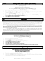
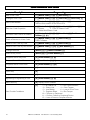
Quick Reference User Guide
Description
Programming
Add a User Code
[*] [Master Code] [*] [0] [*] [New Code] [*]
Change a User Code
[*] [Master Code] [*] [2] [*] [Old Code] [*] [New Code] [*]
View a Slot Number
[*] [Master Code] [*] [3] [*] [User Code] [*]
View the Slot number via the zone LED’s
Edit User Code Properties
[*] [Master Code] [*] [4] [*] [User Code] [*] [2,3 or 4] [*]
2 = Duress
3 = Arm to Disarm Code
4 = Global Arm/Disarm Code
Allocate a User Code to a Partition
[*] [Master Code] [*] [5] [*] [User Code] [*] [Partition
Number] [*] [#]
Teach a Remote to a User Code
[*] [Master Code] [*] [8] [*] [User Code] [*]
Press Tx Button
Delete a User Code by Code
[*] [Master Code] [*] [9] [*] [User Code] [*]
Delete a User Code by Slot Number
[*] [Master Code] [*] [10] [*] [Slot Number] [*]
Change Partitions
[Mode] [1] [*] [Partition Number] [*]
Select a Stay Profile
[Mode] [2] [*] [Profile Number] [*]
Program/Cancel Stay Zone
[3] [Zone Number] [*] [#]
Program/Cancel Buzz Zone
[4] [Zone Number [*] [#]
Program/Cancel Chime Zone
[2] [Zone Number} [*] [#]
Quick Arm
[1]
Quick Stay
[5]
Stay Arm and Go
[6]
Bypassing/Un-bypassing a Zone
[9] [Zone Number] [*] [#]
Alarm Memory
[0] Displays zones violated.
[7]
View Trouble Conditions
27
1 = AC Mains Fail
2 = No Communication
3 = Phone Line
4 = Siren Tamper
5 = Low Battery
6 = Loss of Clock Timer
7 = Engineer Reset
8 = Box Tamper
10 = Tamper on Peripheral
11 = Comms. Failure to Peripheral Device
12 = Loss of Power to Peripheral Device
IDS816 User Manual 700-283-01H Issued January 2009
28
IDS816 User Manual 700-283-01H Issued January 2009