1
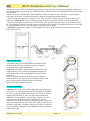
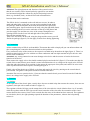
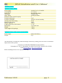
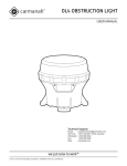
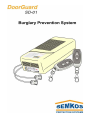
EN
SD-01 Installation and User’s Manual
Thank you for choosing DoorGuard SD-01
ATTENTION: The users should not install DoorGuard SD-01 on their own in any case. The product
should be installed by the LICENSED SERVICE SEMKOS CREW, written on the last page of the present
document or by an alarm system specialized installer.
On the supplier’s website http://www.semkos.gr the specialized installer can watch an audiovisual
performance of the right way to install the product.
Before installing the Burglary Prevention System SD-01 read carefully the following instructions.
PACKAGE CONTENTS
1. Device SD-01
2. Two infra-red sensors, with their wires.
3. Two wireless remote controls, key holder type (SD-RF).
4. Screws and special accessories for application on the wall.
5. Hard paper template, used to mount the device.
6. The present installation and user’s guide.
TABLE OF CONTENTS
INSTRUCTIONS FOR THE SPECIALIZED INSTALLER
1
Introduction
1.1 Description of the product
1.2 Description of the function
1.3 Instructions for the specialized installer
2. Installation
2.1 Placement
2.2 Connections
3.
Function
3.1 Settings
3.2 Remote controls programming
3.3 Voluntary termination of the audio operation
p.3
p.5
p.5
INSTRUCTIONS FOR THE USER
Activation and Deactivation of the alarm standby mode
p.7
Technical features
Technical Features SD-01
Technical Features SD-RF
p.8
Publications’ record of the present user’s guide
Publication 1.00.00
page 2
EN
SD-01 Installation and User’s Manual
INSTRUCTIONS FOR THE SPECIALIZED INSTALLER
1. Introduction
1.1 Description of the product
SD-01 is a clever burglary prevention system located outside the entrance door. It has an infra-red radiation
control zone and it checks the door lock for the timely tracking of the burglary. It has an incorporated
powerful panic siren (105db/1m) and a rechargeable battery that can provide at least 15 hours of backup
operation in case of black out.
1.2 Description of the function
The control of the alarm system is done via wireless remote controls SD-RF, which can also be used as
elegant key holders.
SD-01 is activated by pressing the switch on the remote control with the sign of the closed lock. This function
is stated audiovisually with the red indicative lamp of SD-01, which is constantly turned on (figure 9). In this
state of violation detection the system requires that the two sensors communicate visually constantly and any
violation attempt, e.g. a burglary tool, will result to the entire or partial disruption of this visual
communication, that will trigger the alarm. The alarm continues sounding until the visual contact between the
sensors is restored and the time of the operation of the siren is over (see paragraph 3.1.).
1.3 Instructions for the specialized installer
- Before installing SD-01, make sure the general power switch is turned off.
- Attention! The right placement and function of the system involves that the two sensors will be located
perfectly opposite to one another in a horizontal straight line, without any object interjecting between them
(e.g. doorknob), so that the infra-red communication between them can be continuous, according to the
procedure as described in paragraph 2.1.
-Attention! For the right function of the system and in order to avoid false alarms, the rays of the sun should
not strike vertically the lens of the sensor with the wire of the three inner conductors.
- Help the environment by throwing the batteries in the battery recycling bins.
- Maximum autonomy of the backup function can be succeeded only after a 24 hour continuous charging.
- Even if there is no case of damage do not ever discharge the jumper of the siren (figure 8, page 6, paragraph
3.3)
- For any questions and technical support visit our website: http://www.semkos.gr
Attention! For the right placement of the sensors, at least one common spirit level is necessary.
2. Installation
For the right and quick completion of the installation of the sensors we suggest you to use the special laser
sighting tool SD-SETUP, that you can buy from the supplier of the present product. For more information
please visit our website at www.semkos.gr
2.1 Placement
Firstly place the two sensors on the door according to the following steps and figure 1:
- Measure the distance between the upper outer part of the door frame and the spot where the key hole is and
then mark the door frame with a pencil. Do the same procedure from the other side of the door frame, marking
the same distance. Alternatively, measure the distance from the floor, as long as the floor is level (figure 1b
and 1c).
- Mark 5cm from the flange of the door frame at the exact height that you marked previously. Do the same for
both of the sides of the door frame.
- Make a hole on the door frame with the suitable drill, with diameter of 14mm.
- Measure from the inner side of the door and mark both its sides, right next to the inner sill (at the exact
height that you marked the outer side.) Attention! The right placement and function of the system involves
Publication 1.00.00
page 3
EN
SD-01 Installation and User’s Manual
that the two sensors will be located perfectly opposite to one another in a horizontal straight line without any
object interjecting between them (e.g. doorknob, lock), so that the infra-red communication between them can
be continuous.
- Make a hole with a suitable drill, with a diameter of 8mm, towards the outer hole that you opened on the
door frame of the door, so that the first hole can meet the second one and communicate.
- With the help of an electrician’s cable or a wire, pass the cables of the sensors from the outer side to the
inner side. Attention! The sensor with the two inner conductors should be located at the side of the lock.
- Brace the cables on the perimeter of the door frame, until they reach the spot where you will locate the SD01. The suggested position is the upper corner of the door at the side where the light switches are. At that spot
we usually find the fuse box (with the electric cables) for power supply.
- Attention! Pull the wires slightly, so that nothing is in excess. In that way you can assure that no one can
pull out the sensors.
Right Measurement
If the floor is level you should measure the distance from
the floor to the keyhole of the lock and mark both sides
of the door frame at the same distance.
Attention! The distance from the door should be the same
(approximately 3 cm), so that the imaginable straight line
between the sensors can pass through the keyhole and not
crash on it.
Before opening the holes on the door frame, measure the
distance from the two upper corners of the door frame to the
spots you previously marked and make sure that the
distances between them are the same.
Wrong Measurement
Attention! In case the floor and the upper part of the door frame
are not level, you should measure the height difference and mark
the correct spots on the door frame with a spirit level or with the
sighting tool SD-SETUP. After you make sure that the spots
marked are exactly opposite to one another, only then you can
make the holes on the door frame, to implant the sensors.
Likewise you will check in the case that the two sides of the door
frame converge or deviate from each other. That is, if they are not
parallel to each other. If the door frame is not stable you will first
have to stabilize it and then go on with the procedure of marking
and opening holes
Publication 1.00.00
page 4
EN
SD-01 Installation and User’s Manual
Attention! The right placement and function of the system involves
that the two sensors will be located perfectly opposite to one another
in a horizontal straight line without any object interjecting between
them (e.g. doorknob, lock), so that the infra-red communication
between them can be continuous
The SD-01 device is mounted on the wall with two screws. Ιn order to
mark and make holes on the hole you can use the template found inside
the package. Hold the template on the wall, then mark with a pencil the
two mounting spots. Open two holes on the wall, using the right drill (5mm).
Before mounting the device on the wall take off the top of the plastic and
pass the supply wire and the two wires of the sensors through the two
openings located on the lower left and right side of the plastic base
(beneath the terminal strips).
Then screw the SD-01 on the wall, using the plugs and the screws you will
find in the package (figure 2). Do not apply to much force during tightening.
2.2. Connections
All the terminal strips of SD-01 are detachable. That means that with a simple pull you can unfasten them and
after completing the connection fasten them back to their positions.
First, connect the wires of the sensors to the respective terminal strips located on the right (figure 3). There is a
double terminal strip for the wire with the two inner conductors and one triple terminal strip for the wire with
the two inner conductors.
Attention! Any wrong connection can cause damage to the device and the sensors or lead to the incorrect
function of the device.
Then connect the supply wire to the double terminal strip located on the left (figure 3). First make sure that the
switch of the central electric power board is turned off and that there is no voltage on the supply wire of SD-01.
After that, place the battery in its position (in the gap on the upper part of the plate) and connect its wire to the
white clip located on the electric plate, according to figure 4.
Finally, take off the plastic top of SD-01 on its base and supply the circuit by turning on the central electric
power board. The grilles of the plastic should be located from above.
Attention! Do not ever open the device, if not sure that the central electric power board is turned off and that
there is no voltage in the supply wire of SD-01.
3. Function
3.1. Settings
At the right side of the electric plate, exactly above the two terminal strips that connect the sensors, there are two
regulators, that spin with a small screwdriver (figure 5).
The regulator with the ON sign sets the startup time of the siren after the visual violation from 1 to 15 seconds,
while the regulator with the OFF sign sets the sound extension of the siren after the restoration of the visual
contact between the sensors, from 1 to 60 seconds after the cause of the alarm has been removed. The regulators
are clockwise, that is, the right spinning expands the duration of the parameters, whereas the left spinning
reduces it.
Publication 1.00.00
page 5
EN
SD-01 Installation and User’s Manual
The regulator with the ON sign sets the startup time of the siren
after the visual violation from 1 to 15 seconds, while the regulator
with the OFF sign sets the sound extension of the siren after the
restoration of the visual contact between the sensors, from 1 to
60 seconds after the cause of the alarm has been removed. The
regulators are clockwise, that is, the right spinning expands the
duration of the parameters, whereas the left spinning reduces it.
3.2. Remote controls programming
You will have to enter the code of the control to the register of the SD-01, so that the SD-01 corresponds to the
commands of the remote control. Follow the procedure below to enter the code of the control to the device:
Take off the plastic top of the SD-01 device, so that you can access the electric plate. On the upper left corner of
the plate there is a second small vertical plate with a small grey switch and a red LED right next to it (figure 6).
For the programming follow the steps below:
- Press the switch once.
- Press one of the two switches of SD-RF once.
- Make sure that the red LED is flickering.
- Press the switch of the plate once again.
- Press one of the two switches of SD-RF once again.
- Make sure that the red LED is flickering three times and then turns off.
- The programming procedure is completed successfully.
SD-01 can save codes for 5 different remote controls and the same remote control can be registered in as many
SD-01 devices you wish.
In case you lose one remote control, you have to delete the entire register from SD-01’s memory. Follow this
procedure if you want to delete the register:
Press the switch located on the vertical plate extendedly (upper left corner figure 6) for approximately 8
seconds. Observe the red LED (figure 6), located next to the switch, at first it turns on and after 8 seconds it
turns off. Once the LED is turned off, stop pressing the switch. The deletion is completed.
3.3 Voluntary termination of the audio operation
Before applying the following instruction make sure that the switch of the central electric power board is turned
off and that there is no voltage on the supply wire of SD-01.
In case that you cannot deactivate the alarm (e.g. loss of remote control figure 7) you can isolate the sound of the
siren until the possibility of the activation is enabled.
Publication 1.00.00
page 6
EN
SD-01 Installation and User’s Manual
To deactivate the siren you have to remove a mechanical switch. Take of the plastic top and go back to the point
depicted at figure 8. Catch the blue accessory with your hand and pull it so that it comes out of its position.
Please save the accessory for future use.
Attention! If you apply the above mentioned procedure the burglary prevention system ceases to function
INSTRUCTIONS FOR THE USER
Before using the burglary prevention system please read these instructions carefully.
Activation and Deactivation of the alarm standby mode
The activation and the deactivation of the alarm is succeeded only via remote controls that accompany the
device.
SD-01 enters the standby mode by pressing the switch on the remote control that has the sign of a closed lock.
The device responds with an instant sound signal and the red indicative lamp stays on (figure 9). SD-01 is now
activated and ready to detect any violations.
The deactivation of the alarm is succeeded by pressing the switch on the remote control that has the sign of an
open lock. The device responds with two instant sound signals and the indicative red stays off (figure 9). SD-01
is now deactivated and cannot detect any violations.
The indicative lamp is located right next to the label of the characteristics of SD-01 (figure 9) and shows the
state of function of the device, as described in the following table 1.
Table 1. States of the red indicative lamp (figure 5)
ON
OFF
SD-01 can detect violations (armed alarm)
SD-01 is deactivated
- For the reliable function of SD-01 we suggest you to change
the batteries every 4 years
- For the safe function of SD-01 we suggest you to always use
batteries from the manufacturer, which you can buy from the
store you bought SD-01 or directly from the company SEMKOS.
- You can buy more remote controls from the store you bought
SD-01 or directly from the company SEMKOS.
- You should always keep the outer surface of the sensors (lenses) clean.
- Help the environment by throwing the batteries in the battery recycling bins.
Publication 1.00.00
page 7
EN
SD-01 Installation and User’s Manual
Technical Features
Technical Features SD-01
Power supply
Consumption
Battery type
Automomy
Siren volume
Different remote controls capacity
Function temperature
Function in humidity
Security level of the casing
Μaterial of the casing
Sensors’ diameter
Length of the wires of the sensors
Dimensions
Weight
Total weight of the package
110-240 V AC (-)/50-60Hz
5 VA (max)
Rechargeable NiMH
15 hours (min)
105dB per minute
5
0-45
Till 95% relevant humidity
IP 20
ABS
14 mm
3.5 m
72x116x42 mm
220 gr
350 gr
Technical Features of the remote controls SD-RF
Power supply
Weight
Lithium Ion Battery
35 gr
The manufacturer can make any technical changes without any warning, due to the effort of continuous
improvement of the product.
Licensed Crew SERVICE SEMKOS DoorGuard SD-01:
Sinsinoglou 16, 544 53, Thessaloniki, Tel: 0030 2310 937970, Fax:0030 2310 937026
e-mail:[email protected] http://www.semkos.gr
Before installing ask the user to sign the following.
Publication 1.00.00
page 8